EP3527681A1 - Matériau de type fil d'acier et son procédé de production - Google Patents
Matériau de type fil d'acier et son procédé de production Download PDFInfo
- Publication number
- EP3527681A1 EP3527681A1 EP16918676.4A EP16918676A EP3527681A1 EP 3527681 A1 EP3527681 A1 EP 3527681A1 EP 16918676 A EP16918676 A EP 16918676A EP 3527681 A1 EP3527681 A1 EP 3527681A1
- Authority
- EP
- European Patent Office
- Prior art keywords
- steel wire
- wire rod
- less
- pearlite
- average
- Prior art date
- Legal status (The legal status is an assumption and is not a legal conclusion. Google has not performed a legal analysis and makes no representation as to the accuracy of the status listed.)
- Withdrawn
Links
Images


Classifications
-
- C—CHEMISTRY; METALLURGY
- C22—METALLURGY; FERROUS OR NON-FERROUS ALLOYS; TREATMENT OF ALLOYS OR NON-FERROUS METALS
- C22C—ALLOYS
- C22C38/00—Ferrous alloys, e.g. steel alloys
- C22C38/18—Ferrous alloys, e.g. steel alloys containing chromium
-
- C—CHEMISTRY; METALLURGY
- C21—METALLURGY OF IRON
- C21D—MODIFYING THE PHYSICAL STRUCTURE OF FERROUS METALS; GENERAL DEVICES FOR HEAT TREATMENT OF FERROUS OR NON-FERROUS METALS OR ALLOYS; MAKING METAL MALLEABLE, e.g. BY DECARBURISATION OR TEMPERING
- C21D6/00—Heat treatment of ferrous alloys
- C21D6/002—Heat treatment of ferrous alloys containing Cr
-
- C—CHEMISTRY; METALLURGY
- C21—METALLURGY OF IRON
- C21D—MODIFYING THE PHYSICAL STRUCTURE OF FERROUS METALS; GENERAL DEVICES FOR HEAT TREATMENT OF FERROUS OR NON-FERROUS METALS OR ALLOYS; MAKING METAL MALLEABLE, e.g. BY DECARBURISATION OR TEMPERING
- C21D6/00—Heat treatment of ferrous alloys
- C21D6/005—Heat treatment of ferrous alloys containing Mn
-
- C—CHEMISTRY; METALLURGY
- C21—METALLURGY OF IRON
- C21D—MODIFYING THE PHYSICAL STRUCTURE OF FERROUS METALS; GENERAL DEVICES FOR HEAT TREATMENT OF FERROUS OR NON-FERROUS METALS OR ALLOYS; MAKING METAL MALLEABLE, e.g. BY DECARBURISATION OR TEMPERING
- C21D6/00—Heat treatment of ferrous alloys
- C21D6/008—Heat treatment of ferrous alloys containing Si
-
- C—CHEMISTRY; METALLURGY
- C21—METALLURGY OF IRON
- C21D—MODIFYING THE PHYSICAL STRUCTURE OF FERROUS METALS; GENERAL DEVICES FOR HEAT TREATMENT OF FERROUS OR NON-FERROUS METALS OR ALLOYS; MAKING METAL MALLEABLE, e.g. BY DECARBURISATION OR TEMPERING
- C21D8/00—Modifying the physical properties of ferrous metals or ferrous alloys by deformation combined with, or followed by, heat treatment
- C21D8/06—Modifying the physical properties of ferrous metals or ferrous alloys by deformation combined with, or followed by, heat treatment during manufacturing of rods or wires
-
- C—CHEMISTRY; METALLURGY
- C21—METALLURGY OF IRON
- C21D—MODIFYING THE PHYSICAL STRUCTURE OF FERROUS METALS; GENERAL DEVICES FOR HEAT TREATMENT OF FERROUS OR NON-FERROUS METALS OR ALLOYS; MAKING METAL MALLEABLE, e.g. BY DECARBURISATION OR TEMPERING
- C21D9/00—Heat treatment, e.g. annealing, hardening, quenching or tempering, adapted for particular articles; Furnaces therefor
- C21D9/52—Heat treatment, e.g. annealing, hardening, quenching or tempering, adapted for particular articles; Furnaces therefor for wires; for strips ; for rods of unlimited length
-
- C—CHEMISTRY; METALLURGY
- C21—METALLURGY OF IRON
- C21D—MODIFYING THE PHYSICAL STRUCTURE OF FERROUS METALS; GENERAL DEVICES FOR HEAT TREATMENT OF FERROUS OR NON-FERROUS METALS OR ALLOYS; MAKING METAL MALLEABLE, e.g. BY DECARBURISATION OR TEMPERING
- C21D9/00—Heat treatment, e.g. annealing, hardening, quenching or tempering, adapted for particular articles; Furnaces therefor
- C21D9/52—Heat treatment, e.g. annealing, hardening, quenching or tempering, adapted for particular articles; Furnaces therefor for wires; for strips ; for rods of unlimited length
- C21D9/525—Heat treatment, e.g. annealing, hardening, quenching or tempering, adapted for particular articles; Furnaces therefor for wires; for strips ; for rods of unlimited length for wire, for rods
-
- C—CHEMISTRY; METALLURGY
- C22—METALLURGY; FERROUS OR NON-FERROUS ALLOYS; TREATMENT OF ALLOYS OR NON-FERROUS METALS
- C22C—ALLOYS
- C22C38/00—Ferrous alloys, e.g. steel alloys
- C22C38/001—Ferrous alloys, e.g. steel alloys containing N
-
- C—CHEMISTRY; METALLURGY
- C22—METALLURGY; FERROUS OR NON-FERROUS ALLOYS; TREATMENT OF ALLOYS OR NON-FERROUS METALS
- C22C—ALLOYS
- C22C38/00—Ferrous alloys, e.g. steel alloys
- C22C38/002—Ferrous alloys, e.g. steel alloys containing In, Mg, or other elements not provided for in one single group C22C38/001 - C22C38/60
-
- C—CHEMISTRY; METALLURGY
- C22—METALLURGY; FERROUS OR NON-FERROUS ALLOYS; TREATMENT OF ALLOYS OR NON-FERROUS METALS
- C22C—ALLOYS
- C22C38/00—Ferrous alloys, e.g. steel alloys
- C22C38/02—Ferrous alloys, e.g. steel alloys containing silicon
-
- C—CHEMISTRY; METALLURGY
- C22—METALLURGY; FERROUS OR NON-FERROUS ALLOYS; TREATMENT OF ALLOYS OR NON-FERROUS METALS
- C22C—ALLOYS
- C22C38/00—Ferrous alloys, e.g. steel alloys
- C22C38/04—Ferrous alloys, e.g. steel alloys containing manganese
-
- C—CHEMISTRY; METALLURGY
- C21—METALLURGY OF IRON
- C21D—MODIFYING THE PHYSICAL STRUCTURE OF FERROUS METALS; GENERAL DEVICES FOR HEAT TREATMENT OF FERROUS OR NON-FERROUS METALS OR ALLOYS; MAKING METAL MALLEABLE, e.g. BY DECARBURISATION OR TEMPERING
- C21D2211/00—Microstructure comprising significant phases
- C21D2211/002—Bainite
-
- C—CHEMISTRY; METALLURGY
- C21—METALLURGY OF IRON
- C21D—MODIFYING THE PHYSICAL STRUCTURE OF FERROUS METALS; GENERAL DEVICES FOR HEAT TREATMENT OF FERROUS OR NON-FERROUS METALS OR ALLOYS; MAKING METAL MALLEABLE, e.g. BY DECARBURISATION OR TEMPERING
- C21D2211/00—Microstructure comprising significant phases
- C21D2211/003—Cementite
-
- C—CHEMISTRY; METALLURGY
- C21—METALLURGY OF IRON
- C21D—MODIFYING THE PHYSICAL STRUCTURE OF FERROUS METALS; GENERAL DEVICES FOR HEAT TREATMENT OF FERROUS OR NON-FERROUS METALS OR ALLOYS; MAKING METAL MALLEABLE, e.g. BY DECARBURISATION OR TEMPERING
- C21D2211/00—Microstructure comprising significant phases
- C21D2211/005—Ferrite
-
- C—CHEMISTRY; METALLURGY
- C21—METALLURGY OF IRON
- C21D—MODIFYING THE PHYSICAL STRUCTURE OF FERROUS METALS; GENERAL DEVICES FOR HEAT TREATMENT OF FERROUS OR NON-FERROUS METALS OR ALLOYS; MAKING METAL MALLEABLE, e.g. BY DECARBURISATION OR TEMPERING
- C21D2211/00—Microstructure comprising significant phases
- C21D2211/008—Martensite
-
- C—CHEMISTRY; METALLURGY
- C21—METALLURGY OF IRON
- C21D—MODIFYING THE PHYSICAL STRUCTURE OF FERROUS METALS; GENERAL DEVICES FOR HEAT TREATMENT OF FERROUS OR NON-FERROUS METALS OR ALLOYS; MAKING METAL MALLEABLE, e.g. BY DECARBURISATION OR TEMPERING
- C21D2211/00—Microstructure comprising significant phases
- C21D2211/009—Pearlite
-
- C—CHEMISTRY; METALLURGY
- C22—METALLURGY; FERROUS OR NON-FERROUS ALLOYS; TREATMENT OF ALLOYS OR NON-FERROUS METALS
- C22C—ALLOYS
- C22C38/00—Ferrous alloys, e.g. steel alloys
- C22C38/06—Ferrous alloys, e.g. steel alloys containing aluminium
-
- C—CHEMISTRY; METALLURGY
- C22—METALLURGY; FERROUS OR NON-FERROUS ALLOYS; TREATMENT OF ALLOYS OR NON-FERROUS METALS
- C22C—ALLOYS
- C22C38/00—Ferrous alloys, e.g. steel alloys
- C22C38/18—Ferrous alloys, e.g. steel alloys containing chromium
- C22C38/22—Ferrous alloys, e.g. steel alloys containing chromium with molybdenum or tungsten
-
- C—CHEMISTRY; METALLURGY
- C22—METALLURGY; FERROUS OR NON-FERROUS ALLOYS; TREATMENT OF ALLOYS OR NON-FERROUS METALS
- C22C—ALLOYS
- C22C38/00—Ferrous alloys, e.g. steel alloys
- C22C38/18—Ferrous alloys, e.g. steel alloys containing chromium
- C22C38/24—Ferrous alloys, e.g. steel alloys containing chromium with vanadium
-
- C—CHEMISTRY; METALLURGY
- C22—METALLURGY; FERROUS OR NON-FERROUS ALLOYS; TREATMENT OF ALLOYS OR NON-FERROUS METALS
- C22C—ALLOYS
- C22C38/00—Ferrous alloys, e.g. steel alloys
- C22C38/18—Ferrous alloys, e.g. steel alloys containing chromium
- C22C38/26—Ferrous alloys, e.g. steel alloys containing chromium with niobium or tantalum
-
- C—CHEMISTRY; METALLURGY
- C22—METALLURGY; FERROUS OR NON-FERROUS ALLOYS; TREATMENT OF ALLOYS OR NON-FERROUS METALS
- C22C—ALLOYS
- C22C38/00—Ferrous alloys, e.g. steel alloys
- C22C38/18—Ferrous alloys, e.g. steel alloys containing chromium
- C22C38/28—Ferrous alloys, e.g. steel alloys containing chromium with titanium or zirconium
-
- C—CHEMISTRY; METALLURGY
- C22—METALLURGY; FERROUS OR NON-FERROUS ALLOYS; TREATMENT OF ALLOYS OR NON-FERROUS METALS
- C22C—ALLOYS
- C22C38/00—Ferrous alloys, e.g. steel alloys
- C22C38/18—Ferrous alloys, e.g. steel alloys containing chromium
- C22C38/32—Ferrous alloys, e.g. steel alloys containing chromium with boron
Definitions
- the present invention relates to a steel wire rod used as a material for an overhead power transmission line and various ropes, and a manufacturing method thereof.
- Aluminum conductor steel-reinforced cable (hereinafter, "ACSR") is an electric wire having a configuration in which a zinc-coated steel wire is disposed at the center and hard aluminum wires are concentrically stranded around the steel wire, with each layer having alternating lays.
- the steel wire for ACSR use has been mainly playing a role as a tension member for aluminum wires.
- As the steel wire for ACSR use a steel wire obtained by drawing a pearlitic steel and performing zinc coating thereon, an aluminum-clad steel wire obtained by drawing a steel wire rod having an aluminum layer formed as the surface layer to improve corrosion resistance, and the like have been used in the related art.
- Patent Document 1 discloses a method of reducing the specific gravity of an ACSR by using carbon fiber as the core wire of the ACSR.
- Patent Document 2 discloses a method of improving the electric conductivity of a steel wire by specifying the amounts of C, Si, and Mn of the steel wire to small amounts.
- Patent Document 3 discloses a method of refining the pearlite block size and lamellar spacing of a steel wire by adding a small amount of Ni to the steel wire, thereby improving the value of a reduction in area and the strength of the steel wire.
- the ACSR obtained by the technique disclosed in Patent Document 1 described above uses expensive carbon fiber as its core wire, so that a higher cost is incurred compared to an ACSR using a steel wire as its core wire.
- the technique disclosed in Patent Document 2 since the amounts of the alloying elements of the steel wire are reduced, it is difficult to secure the strength as the tension member of the steel core of the steel wire.
- N is solid soluted into lamellar ferrite by adding Ni and the electric resistance of the steel wire is increased, and thus, which is not preferable from the viewpoint of reducing the electric resistance.
- the present invention has been made taking the foregoing circumstances into consideration, and an object thereof is to provide a steel wire rod which has a high tensile strength and a relatively low electric resistivity with respect to the tensile strength, and furthermore enables a steel wire having excellent torsional properties to be manufactured, and a manufacturing method thereof.
- an object of the present invention is to provide a steel wire rod having a relatively high electric conductivity (that is, low electric resistivity) with respect to a high tensile strength, and a manufacturing method thereof.
- the tensile strength of a steel wire and the electric resistivity of a steel wire rod have a proportional relationship.
- the inventors investigated the relationship between the tensile strength TS (MPa) and the electric resistivity ⁇ ( ⁇ cm) of a steel wire rod in the related art, and as a result, found that the electric resistivity of a steel wire rod for ACSR use in the related art is practically in the following range.
- the electric resistivity of the steel wire rod is improved from the level in the related art. ⁇ ⁇ 0.0155 ⁇ TS + 1.25 ⁇ ⁇ 0.0155 ⁇ TS ⁇ 0.95
- a steel wire rod having high electric conductivity means a steel wire rod having an electric resistivity equal to or less than the electric resistivity threshold obtained based on Formula (1) or Formula (2).
- the gist of the present invention is as follows.
- a steel wire rod which has a high tensile strength and a relatively low electric resistivity with respect to the tensile strength, and furthermore enables a steel wire having excellent torsional properties to be manufactured, and a manufacturing method thereof.
- a steel wire rod according to an embodiment of the present invention and a manufacturing method thereof will be described below.
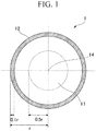
- a steel wire rod of this embodiment shown in FIG. 1 has a predetermined chemical composition, and the structure in a central part 11, which is a region from the central axis of the steel wire rod 1 to r ⁇ 0.5 and the structure in a surface part 12, which is a region from the circumferential surface of the steel wire rod to r ⁇ 0.1 are controlled to predetermined morphologies.
- r is the distance from the circumferential surface of the steel wire rod 1 to the central axis of the steel wire rod 1.
- the unit of the chemical composition is mass%.
- the C has an effect of increasing the strength of the steel wire rod by increasing the cementite fraction of a pearlite structure in the steel and refining the lamellar spacing of the pearlite structure.
- the C content is set to 0.60% or more.
- the C content is preferably 0.65% or more, and more preferably 0.70% or more.
- the upper limit of the C content is set to 1.10%.
- the C content is preferably 1.05% or less, more preferably 1.00% or less, and even more preferably 0.95% or less.
- Si is an element that improves the hardenability of the steel wire rod, is an element effective for suppressing the formation of proeutectoid cementite during patenting, and is an element effective for solid solution strengthening and deoxidation of the steel wire rod.
- the Si content is less than 0.005%, it becomes difficult to control the pearlite structure to a predetermined configuration, and in a case where the C content is large, it becomes difficult to suppress the formation of proeutectoid cementite. Therefore, the lower limit of the Si content is set to 0.005%.
- Si segregates in the ferrite of the pearlite structure and increases the electric resistivity of the steel wire rod. When Si is contained in an amount exceeding 0.350%, the electric resistivity of the steel wire rod is significantly increased. Therefore, the Si content is defined as 0.005% to 0.350%.
- the Si content of the steel wire rod may be set to 0.100% to 0.350%.
- the Si content of the steel wire rod may be set 0.005% or more and less than 0.100%.
- the Si content may set to preferably 0.010% or more, and more preferably 0.030% or more.
- the Si content may be set to preferably 0.250% or less, more preferably 0.200% or less, and even more preferably 0.150% or less.
- Mn is a deoxidizing element, and is an element that has an action of suppressing red brittleness by fixing S in the steel as MnS and suppresses a decrease in conductivity due to solid solute S.
- Mn reduces the area ratio of the proeutectoid ferrite structure of the steel wire rod by improving the hardenability of the steel wire rod during patenting, and has an effect of increasing the strength of the steel wire rod.
- the lower limit of the Mn content is set to 0.10%.
- Mn lowers the conductivity of steel. Therefore, the upper limit of the Mn content is set to 0.90%.
- the upper limit of the Mn content is set to preferably 0.80% or less, and more preferably 0.60% or less.
- Cr is an element that improves hardenability, and is an element that increases the tensile strength of the steel wire rod by decreasing the lamellar spacing of the pearlite. In order to obtain this effect, it is necessary to set the Cr content to 0.010% or more.
- the Cr content is more preferably 0.020% or more.
- Cr sometimes decreases the conductivity. In order to prevent the decrease in conductivity, the upper limit of the Cr content is set to 0.300%.
- the Cr content is more preferably 0.250% or less.
- the amounts of N, P, and S are limited as follows. Since N, P, and S are not necessary for the steel wire rod according to this embodiment, the lower limits of the amounts of N, P, and S are 0%.
- N decreases the ductility of steel due to strain aging during cold working.
- the N content exceeds 0.0100%, the ductility of the steel wire rod is decreased and the conductivity is also decreased. Therefore, the N content is limited to 0.0100% or less.
- the N content is preferably 0.0080% or less, and more preferably 0.0050% or less.
- P contributes to solid solution strengthening of ferrite, but significantly reduces the ductility of the steel wire rod.
- the P content exceeds 0.030%, the deterioration in drawability during drawing of a steel wire rod into a steel wire becomes significant. Therefore, the P content is limited to 0.030% or less.
- the P content is preferably 0.012% or less.
- S is an element that causes red brittleness and further reduces the ductility of steel.
- the S content exceeds 0.030%, the ductility of the steel wire rod is significantly decreased, so that the S content is limited to 0.030% or less.
- the S content is preferably 0.010% or less.
- the steel wire rod according to this embodiment may contain one or more elements selected from the group consisting of Al, Ti, V, Nb, Mo, and B, in addition to the above mentioned elements.
- the steel wire rod according to this embodiment can exhibit excellent properties without containing Al, Ti, V, Nb, Mo, and B, the lower limits of the amounts of Al, Ti, V, Nb, Mo, and B are 0%.
- Al is an element which is a deoxidizing element, and can fix N and refine the austenite grain size by forming nitrides.
- the Al content may be set to 0.001 % or more.
- the upper limit of the Al content is set to 0.070%.
- the Al content is preferably 0.060% or less, and more preferably 0.050% or less.
- Ti is an element which is a deoxidizing element and can refine the austenite grain size by forming carbonitrides.
- the Ti content may be set to 0.002% or more.
- the upper limit of the Ti content is set to 0.030%.
- the Ti content is preferably less than 0.025%.
- V is an element that improves hardenability, and improves the tensile strength of the steel by precipitating as carbonitrides.
- the V content may be set to be more than 0%, or 0.002% or more.
- the upper limit of the V content is set to 0.100%.
- the V content is preferably 0.080% or less.
- Nb is an element that improves hardenability, and is an element that can refine the austenite grain size by precipitating as carbides.
- the Nb content may be set to be more than 0%, or 0.002% or more.
- the Nb content is set to 0.050% or less.
- the Nb content is preferably 0.002% to 0.020%.
- Mo is an element that improves hardenability and reduces the amount of proeutectoid ferrite.
- the Mo content may be set to be more than 0%, or 0.02% or more.
- the upper limit of the Mo content is set to 0.20%.
- the Mo content is preferably 0.10% or less.
- the B is an element that improves hardenability, and is an element that improves the amount of pearlite by suppressing the formation of proeutectoid ferrite.
- the B content may be set to 0.0003% or more.
- the B content is preferably set to 0.0003% to 0.0030%.
- the B content is more preferably set to 0.0020% or less.
- the remainder of the chemical composition of the steel wire rod according to this embodiment contains iron and impurities.
- the impurities are elements that are incorporated from raw materials or a steel manufacturing process, and mean elements that are acceptable in a range in which the steel wire rod according to this embodiment is not adversely affected.
- the target value of the tensile strength of the steel wire rod according to this embodiment is preferably 1050 MPa or more, and more preferably 1100 MPa or more.
- the central part 11 and the surface part 12 of the steel wire rod 1 according to this embodiment needs to have the following structures. There is no need to separately control the configuration of the transition region between the central part 11 and the surface part 12 as long as the configurations in the central part 11 and the surface part 12 are appropriately controlled. Therefore, the configuration of the transition region of the steel wire rod according to this embodiment is not particularly limited.
- the tensile strength of the steel wire rod according to this embodiment is not limited to the above mentioned target value, and may be set depending on the application.
- the structure in the central part includes 80 area% to 100 area% of the pearlite structure, and 0 area% or more and less than 20 area% of a structure other than pearlite, such as proeutectoid ferrite, a bainite structure, proeutectoid cementite, martensite, and the like.
- a structure other than pearlite such as proeutectoid ferrite, a bainite structure, proeutectoid cementite, martensite, and the like.
- the lower limit of the amount of pearlite in the central part of the steel wire rod according to this embodiment may be set to 82 area%, 85 area%, 87 area%, 90 area%, or 92 area%, and the upper limit of the amount of the structure other than pearlite may be set to 18 area%, 15 area%, 13 area%, 10 area%, or 8 area%. Since the structure in the central part of the steel wire rod according to this embodiment does not require the structure other than pearlite, the upper limit value of the amount of pearlite in the central part of the steel wire rod according to this embodiment is 100 area%, and the lower limit of the amount of the structure other than pearlite is 0 area%.
- the upper limit of the amount of pearlite in the central part of the steel wire rod according to this embodiment may be set to 99 area%, 98 area%, or 97 area%, and the lower limit of the amount of the structure other than pearlite may be set to 1 area%, 2 area%, or 3 area%.
- the structure in the surface part includes 70 area% to 100 area% of pearlite.
- the surface part and the central part of the steel wire rod differ in processing and thermal history in a manufacturing stage and a heat treatment stage of the steel wire rod, and the actual transformation temperature at the surface part is lower than at the central part. Therefore, the amount of pearlite in the surface part of the steel wire rod is typically smaller than the amount of pearlite in the central part of the steel wire rod.
- the amount of pearlite in the surface part of the steel wire rod is less than 70%, the ductility of the surface part of the steel wire rod becomes insufficient, so that the torsional performance of the steel wire rod is deteriorated.
- the amount of pearlite in the surface part of the steel wire rod according to this embodiment is set to 70 area% or more.
- the lower limit of the amount of pearlite in the surface part of the steel wire rod may be set to 72 area%, 75 area%, or 80 area%. Since the structure in the surface part of the steel wire rod according to this embodiment does not require a structure other than pearlite, the upper limit of the amount of pearlite in the surface part of the steel wire rod according to this embodiment is 100 area%, and the lower limit of the amount of the structure other than pearlite is 0 area%.
- the upper limit of the amount of pearlite in the surface part of the steel wire rod according to this embodiment may be set to 99 area%, 98 area%, or 97 area%, and the lower limit of the amount of the structure other than pearlite may be set to 1 area%, 2 area%, or 3 area%.
- the structure other than pearlite included in the surface part of the steel wire rod as in the central part of the steel wire rod, proeutectoid ferrite, a bainite structure, proeutectoid cementite, martensite, and the like are exemplified.
- the surface part of the steel wire rod may include a structure of which the kind cannot be identified due to severe deformation.
- the amount of pearlite in the surface part of the steel wire rod is a value that does not include the amount of the structure of which the kind cannot be identified.
- Pearlite has a lamellar structure having ferrite and cementite alternating in a layered manner.
- lamellar ferrite ferrite constituting pearlite
- lamellar cementite cementite constituting pearlite
- the average lamellar spacing of the pearlite structure in the central part of the steel wire rod according to this embodiment is in a range of 50 nm to 100 nm.
- the conductivity is increased as the lamellar spacing is decreased. Therefore, the average lamellar spacing of the pearlite structure in the central part of the steel wire rod is set to 100 nm or less.
- the upper limit of the average lamellar spacing of the pearlite structure in the central part of the steel wire rod is preferably 98 nm, 95 nm, 93 nm, or 90 nm.
- the lower limit thereof is set to 50 nm.
- the average length of the lamellar cementite in the pearlite in the central part of the steel wire rod according to this embodiment is correlated with the conductivity of the steel wire rod, and as the lamellar cementite is divided and thus the average length of the lamellar cementite is decreased, the conductivity of the steel wire rod is increased.
- the average length of the lamellar cementite in the central part of the steel wire rod exceeds 1.9 ⁇ m, the conductivity of the steel wire rod is not sufficiently improved. Therefore, the average length of the lamellar cementite in the pearlite in the central part of the steel wire rod according to this embodiment is set to 1.9 ⁇ m or less.
- the average length of the lamellar cementite in the pearlite in the central part is preferably 1.8 ⁇ m or less, 1.6 ⁇ m or less, 1.5 ⁇ m or less, 1.4 ⁇ m or less, or 1.3 ⁇ m or less.
- the average length of the lamellar cementite in the pearlite in the central part of the steel wire rod according to this embodiment needs to be 1.9 ⁇ m or less.
- the present inventors found that as the average pearlite block size in the central part decreases, the lamellar cementite is less likely to be divided during tempering.
- the average pearlite block size in the central part is less than 15.0 ⁇ m, it is extremely difficult to set the average length of the lamellar cementite in the pearlite in the central part to be 1.9 ⁇ m or less. Therefore, the average pearlite block size in the central part of the steel wire rod according to this embodiment needs to be 15.0 ⁇ m or more.
- the average pearlite block size in the central part of the steel wire rod may be defined as 17.0 ⁇ m or more, 18.0 ⁇ m or more, or 20.0 ⁇ m or more.
- the average pearlite block size in the central part increases, the ductility of the steel wire rod is decreased. Due to the feature in which only the average pearlite block size in the surface part of the steel wire rod is reduced, which will be described later, the ductility of the steel wire rod can be secured without hindering the division of the lamellar cementite of the steel wire rod. However, in a case where the average pearlite block size in the central part exceeds 30.0 ⁇ m, the ductility of the steel wire rod cannot be preferably maintained even if this feature is utilized. Therefore, the average pearlite block size in the central part needs to be 30.0 ⁇ m or less.
- the average pearlite block size in the central part may be defined as 27.0 ⁇ m or less, 25.0 ⁇ m or less, or 20.0 ⁇ m or less.
- the structure in the surface part of the steel wire rod affects the ductility of a wire (steel wire) obtained by drawing the steel wire rod, against torsional deformation.
- a wire steel wire
- the structure in the surface part of the steel wire rod affects the ductility of a wire (steel wire) obtained by drawing the steel wire rod, against torsional deformation.
- the PBS ratio is more preferably set to 0.85 or less.
- the lower limit of the PBS ratio is not particularly limited, it is difficult to set the PBS ratio to be less than 0.40 in consideration of facility capability and the like, so that the lower limit of the PBS ratio may be set to 0.40, 0.50, or 0.60.
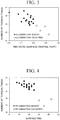
- FIG. 3 is a graph showing the relationship between the PBS ratios of low Si steel wire rods and the number of torsions of wires obtained from these low Si steel wire rods.
- the present inventors prepared various low Si steel wire rods and measured the PBS ratios of these low Si steel wire rods and the number of torsions of wires obtained from these low Si steel wire rods. As a result, as shown in FIG.
- the PBS ratio of the low Si steel wire rod decreases, the number of torsion of the wire is increased, and particularly in a case where the PBS ratio is 0.80 or less, the number of torsion of the wire is significantly increased.
- the Si content is less than 0.10%, the pearlite block growth rate becomes faster and the pearlite block size tends to become coarse. Therefore, in comparison to the structure in the central part, the PBS ratio is more suitable as an index indicating the ductility of the structure in the surface layer, than the absolute value of the PBS. Delamination had occurred in a wire obtained from a low Si steel wire rod having a PBS ratio of more than 0.87 during a test.
- the average pearlite block size in the surface part of the steel wire rod is set to preferably 17.0 ⁇ m or less, and more preferably 16.0 ⁇ m or less.
- FIG. 4 is a graph showing the relationship between the surface PBSs of high Si steel wire rods and the number of torsions of wires obtained from these steel wire rods.
- the present inventors prepared various high Si steel wire rods and measured the surface PBSs of these high Si steel wire rods and the number of torsions of wires obtained from these low Si steel wire rods. As a result, as shown in FIG.
- the relationship between the tensile strength TS (MPa) and the electric resistivity ⁇ ( ⁇ cm) of the steel wire rod is defined using Formula (1) for the case of high Si steel wire rods and Formula (2) for low Si steel wire rods. ⁇ ⁇ 0.0155 ⁇ TS + 1.25 ⁇ ⁇ 0.0155 ⁇ TS ⁇ 0.95
- a high Si steel wire rod is used for a product which is not strictly restricted in terms of conductivity but requires high tensile strength.
- a low Si steel wire rod is used for a product which is not strictly restricted in terms of tensile strength but requires high conductivity.
- the steel wire rod according to this embodiment has the above described features and thus has the tensile strength and electric resistivity satisfying Formula (1) or Formula (2).
- a method of specifying the structure of the steel wire rod according to this embodiment will be described.
- a section which is parallel to the longitudinal direction of the steel wire rod and includes the central axis of the steel wire rod is referred to as an L-section
- a section perpendicular to the longitudinal direction of the steel wire rod is referred to as a C-section.
- the average lamellar spacing of the pearlite in the central part 11 is obtained by performing mirror polishing on the L-section of the steel wire rod, performing picral etching thereon, observing the structure with a field emission scanning electron microscopy (FE-SEM), and analyzing the observation result of the structure.
- the observation of the structure is performed at nine observation points 13 shown in FIG. 2 .
- the observation points 13 in the L-section of the steel wire rod 1 are disposed at the vertices, the center, and the midpoints of the four sides of a rectangular region in which the length of the four sides is the same as the radius r of the steel wire rod 1, two sides are parallel to the longitudinal direction of the steel wire rod, and the center is on a central axis 14 of the steel wire rod 1.
- the surface of a section excluding a region, in which 30% or more of the region is point-like cementite having an aspect ratio of 3 or less, is photographed with the FE-SEM at a magnification of 10,000-fold.
- An electronic image of the photographed region is analyzed to binarize the part of lamellar cementite and is subjected to line segmentation with no thickness.
- vertical and horizontal lines are drawn for each pixel of the electronic image, and 1/2 of the average value of the lengths of the segments partitioned by the cementite is taken as the average lamellar spacing.
- the average lamellar spacing is based on the principle described in " Quantitative Microscopy” (Makishima et al., issued on July 30, 1972, by Uchida Rokakuho Publishing Co., Ltd.) p. 115 to p. 117 .
- the average value of the average lamellar spacings in the nine FE-SEM images for the nine observation points 13 can be regarded as the average lamellar spacing in the central part of the steel wire rod.
- the average length of the lamellar cementite in the pearlite structure in the central part 11 is obtained by the following procedure.
- the part of the lamellar cementite is binarized in the above described manner, and image analysis is performed thereon, whereby the average length of the lamellar cementite of the pearlite include in the FE-SEM images is calculated.
- the average value of the average lamellar cementite lengths in the nine FE-SEM images for the nine observation points 13 can be regarded as the average length of the lamellar cementite in the central part.
- the fraction of the pearlite structure in the central part is obtained by the following procedure.
- Metallographic structure photographs of the nine observation points 13 with the average lamellar spacing on the cut surface of the steel wire rod are taken at a magnification of 2,000-fold.
- a structure part other than pearlite is marked and enclosed, and the area ratio thereof is measured by image analysis.
- the difference of the area ratio of the structure part other than pearlite from the whole is the area ratio of pearlite in each of the photographs.
- the average value of the area ratios of pearlite in the photographs can be regarded as the fraction of the pearlite structure in the central part.
- the fraction of the pearlite structure in the surface part which is a region from the circumferential surface of the steel wire rod to r ⁇ 0.1 is obtained by the following procedure.
- Metallographic structure photographs centered on a depth of r ⁇ 0.05 from the circumferential surface of the steel wire rod are taken at least at four points in the C-section of the steel wire rod (the section perpendicular to the rolled surface) at a magnification of 2,000-fold. It is preferable that the photographed points are uniformly arranged along the outer circumference of the C-section, and for example, in a case where the number of photographed points is four, it is preferable that the photographed points are arranged every 90° along the outer circumference of the C-section.
- the area ratio of pearlite in the metallographic structure photographs may be obtained by the same method as the method of measuring the fraction of the pearlite structure in the central part.
- the average value of the area ratios of pearlite in the photographs can be regarded as the fraction of the pearlite structure in the surface part.
- the average pearlite block sizes in the central part and the surface part of the steel wire rod are obtained by an electron back scattered diffraction pattern (EBSD) method.
- the average pearlite block size in the central part is obtained by measuring, for the nine observation points 13 shown in FIG. 2 in the L-section of the steel wire rod, the average pearlite block size in each visual field with a visual field size of 250 ⁇ m ⁇ 250 ⁇ m using the EBSD method, and thereafter calculating the average value of the average pearlite block sizes of the visual fields.
- a region surrounded by boundaries with an orientation difference of 9° or more is regarded as one pearlite block grain, and is analyzed using the Johnson-Saltykov measurement method.
- the average pearlite block size in the surface part is obtained by performing measurement on at least four observation points uniformly arranged along the outer circumference of the C-section in the C-section of the steel wire rod, in the same manner as for the central part.
- the center of the measurement visual field is set to a depth of r ⁇ 0.05 from the circumferential surface of the steel wire rod.
- the electric resistance of the steel wire rod is measured by the following procedure. After removing the scale on the surface layer of the steel wire rod and correcting the steel wire rod into a straight bar, the electric resistance thereof is measured by the four-terminal method. The length and current value to be measured are selected according to the facility within a range in which the temperature of the steel wire rod is not changed by energization, and are measured up to the third digit of the significant digits.
- the manufacturing method of the steel wire rod of this embodiment includes: S1 of casting a bloom; S2 of heating the bloom; S3 of retaining the temperature of the bloom; S4 of hot rolling the bloom after the retaining to obtain a hot rolled steel; S5 of water cooling the hot rolled steel; S6 of winding the hot rolled steel after the water cooling; S7 of patenting the hot rolled steel after the winding; and S8 of tempering the hot rolled steel after the patenting to obtain a steel wire rod.
- the manufacturing conditions are described in detail below.
- a bloom having the chemical composition of the steel wire rod according to this embodiment is manufactured by continuous casting or the like.
- a billet may also be obtained by blooming the bloom before the hot rolling described later.
- Heating S2 Heating Temperature 1150°C or Higher and 1250°C or Lower
- the bloom is heated to a heating temperature at which the average temperature of the cross section is in a range of 1150°C to 1250°C before hot rolling, and is then retained at the heating temperature for 600 seconds or longer.
- the maximum temperature of the bloom in the heating S2 is referred to as the heating temperature.
- carbonitrides contained in the bloom are insufficiently solutionized, and the average pearlite block size in the central part is outside of the defined range described above. As described above, when the average pearlite block size in the central part is not in the defined range, the division of the lamellar cementite does not proceed.
- the average cementite length of the lamellar cementite in the central part also falls outside the above described range, and the conductivity of the steel wire rod is impaired.
- the retention time is preferably 7200 seconds or shorter from the viewpoint of suppressing decarburization.
- the billet obtained by cooling the bloom once after the rolling and performing heating and retaining thereon is hot rolled into a hot rolled steel.
- the finishing temperature needs to be 950°C to 1050°C.
- the average pearlite block size in the central part falls outside the defined range.
- the reason is that when finishing temperature is higher than 1050°C, austenite grains after the hot rolling are coarsened, and thus pearlite is insufficiently formed in the subsequent cooling, whereby the ductility of the surface part is not obtained.
- the finishing temperature of lower than 950°C it is difficult for the ratio between the pearlite block sizes in the surface part and the central part to be in the defined range.
- Winding S6 Winding Temperature 780°C or Higher and 840°C or Lower
- Patenting S7 Time 9 Seconds to 25 Seconds from End of Winding to Start of Immersion, Molten Salt Temperature 450°C or Higher and T1°C or Lower, and Immersion Time 20 Seconds to 200 Seconds
- the hot rolled steel after finish rolling is water cooled and wound.
- the water cooling stop temperature and the winding temperature are set to be in a range of 780°C to 840°C.
- the wound hot rolled steel is patented by being immersed for 20 seconds or longer in a molten salt at a temperature of 450°C or higher and T1°C or lower, within 9 seconds to 25 seconds after the winding.
- T1 is a value defined by Formula (3) described below.
- the symbol " r' " included in Formula (3) represents the radius of the hot rolled steel (that is, the radius of the hot rolled steel) in units of mm.
- the water cooling, winding, and patenting are the most important for controlling the configuration of the pearlite of the steel wire rod.
- the immersion time in the molten salt is preferably 200 seconds or shorter from the viewpoint of productivity.
- T 1 ° C ⁇ r ′ mm ⁇ 16 + 580
- the average pearlite block size in the surface part of the steel wire rod does not become 0.87 times or less the average pearlite block size in the central part. The reason is that the austenite grain size in the surface part becomes coarse and the pearlite block size also becomes coarse.
- the water cooling is started immediately after the completion of the hot rolling. Therefore, the water cooling start temperature becomes substantially the same as the finishing temperature described above. It is presumed that even in a case where the water cooling start temperature is lower than 950°C, there is concern that the configuration of the pearlite may not be appropriately controlled.
- the amount of the pearlite in the central part of the steel wire rod becomes less than 80 area%, or the average lamellar spacing of the pearlite in the central part of the steel wire rod exceeds 100 nm.
- the reason is that, for example, in a case where the molten salt temperature is lower than 450°C, the formation of the bainite structure becomes dominant and the fraction of the pearlite structure is decreased.
- the reason is that, when the molten salt temperature is the temperature T1 or higher, the lamellar spacing is increased and exceeds 100 nm.
- the subsequent processes are performed while pearlitic transformation is not completed, so that the pearlite fraction and the lamellar spacing cannot be controlled.
- the patented hot rolled steel is heated to a tempering temperature in a temperature range of 540°C or higher, retained at this tempering temperature for 30 seconds or longer, and then tempered by being cooled to room temperature.
- the tempering time is preferably 600 seconds or shorter.
- the tempering temperature is the maximum heating temperature in tempering S8, and the tempering time is the time during which the temperature of the hot rolled steel is retained at the tempering temperature.
- the lamellar cementite in the central part is divided, and a steel wire rod in which the average cementite length of the lamellar cementite in the central part is 1.9 ⁇ m or less is obtained.
- the tempering temperature and the tempering time is insufficient, the division of the lamellar cementite does not proceed sufficiently, and the average cementite length of the lamellar cementite in the central part of the steel wire rod exceeds 1.9 ⁇ m, so that the conductivity of the steel wire rod is impaired.
- the tempering temperature is too high, the strength is decreased.
- the steel wire rod according to this embodiment has the features in which the central part contains 80 area% to 100 area% of pearlite, the average lamellar spacing of the pearlite in the central part is 50 nm to 100 nm, and the average cementite length of lamellar cementite in the central part is 1.9 ⁇ m or less, and thus has high tensile strength and conductivity.
- Such high tensile strength and conductivity obtained by the above features are maintained even after drawing of the steel wire rod, so that a steel wire obtained by drawing the steel wire rod according to this embodiment also has high tensile strength and conductivity.
- the steel wire rod according to this embodiment has the features in which the average pearlite block size in the surface part is 0.87 times or less the average pearlite block size in the central part, so that the ductility of the surface part is good. Therefore, the steel wire obtained by drawing the steel wire rod according to this embodiment has excellent torsional properties. That is, with the steel wire rod according to this embodiment, a steel wire excellent in all of tensile strength, conductivity, and torsional properties is obtained.
- the hot rolled steels were water cooled to winding temperatures shown in Tables 3 and 4 and wound. Thereafter, a patenting treatment was performed by immersing the hot rolled steels in a salt bath having salt temperatures shown in Tables 3 and 4, whereby pearlitic transformation was completed, within 9 seconds to 25 seconds after the winding. The immersion time of the hot rolled steels in the salt bath was set to 30 seconds. Thereafter, tempering was performed on the hot rolled steels to retain the temperature at tempering temperatures shown in Tables 3 and 4 for a tempering time shown in Tables 3 and 4 and thereafter cool the hot rolled steels to room temperature, whereby steel wire rods were obtained.
- the amount of pearlite contained in the central part of the steel wire rod was obtained by taking structure photographs of nine observation points shown in FIG. 2 in the L-section of the steel wire rod using the FE-SEM, specifying a non-pearlite region included in each structure photograph, obtaining the area ratio of the non-pearlite region of each structure photograph through image analysis, calculating the area ratio of pearlite of each structure photograph based on the area ratio of the non-pearlite region, and averaging the area ratios of pearlite of the structure photographs.
- the amount of pearlite contained in the surface part of the steel wire rod (the fraction of the pearlite structure in the surface part) was obtained by taking structure photographs of four observation points uniformly arranged along the outer circumference of the C-section in the C-section of the steel wire rod and centered on a depth of r ⁇ 0.05 from the circumferential surface of the steel wire rod, using the FE-SEM, specifying a non-pearlite region included in each structure photograph, obtaining the area ratio of the non-pearlite region of each structure photograph through image analysis, calculating the area ratio of pearlite of each structure photograph based on the area ratio of the non-pearlite region, and averaging the area ratios of pearlite of the structure photographs.
- the average pearlite block size (central PBS) in the central part of the steel wire rod was obtained by measuring, for the nine observation points 13 shown in FIG. 2 in the L-section of the steel wire rod, the average pearlite block size of each visual field with a visual field size of 250 ⁇ m ⁇ 250 ⁇ m using the EBSD method, and thereafter calculating the average value of the average pearlite block sizes of the visual fields.
- a region surrounded by boundaries with an orientation difference of 9° or more was regarded as one pearlite block grain, and was analyzed using the Johnson-Saltykov measurement method.
- the average pearlite block size (surface PBS) in the surface part of the steel wire rod was obtained by performing measurement on at least four observation points uniformly arranged along the outer circumference of the C-section in the C-section of the steel wire rod, in the same manner as for the central part.
- the center of the measurement visual field was set to a depth of r ⁇ 0.05 from the circumferential surface of the steel wire rod.
- the ratio (surface / central PBS ratio) between the average pearlite block size in the surface part of the steel wire rod and the average pearlite block size in the central part of the steel wire rod was obtained by dividing the surface PBS by the central PBS described above.
- the surface PBS, and/or central PBS, and the PBS ratio of the steel wire rod in which the amount of pearlite was outside the defined ranges of the present invention are indicated by diagonal lines.
- the average lamellar spacing of the pearlite in the central part of the steel wire rod was obtained by taking structure photographs of the nine observation points shown in FIG. 2 in the L-section of the steel wire rod using the FE-SEM, obtaining the average lamellar spacing of the pearlite included in each structure photograph through the image analysis described above, and further averaging the average lamellar spacings of the structure photographs.
- the average length of the lamellar cementite in the central part of the steel wire rod was obtained by taking structure photographs of the nine observation points shown in FIG. 2 in the L-section of the steel wire rod using the FE-SEM, obtaining the average length of the lamellar cementite of the pearlite included in each structure photograph through the image analysis described above, and further averaging the average lengths of the lamellar cementite of the structure photographs.
- the tensile strength TS of the steel wire rod was obtained by a tension test.
- three tension test pieces having a length of 350 mm were prepared, the tension test was conducted on each tension test piece at room temperature at a tension rate of 10 mm/min, and the average of the tensile strengths of the three tension test pieces was taken as the tensile strength of the steel wire rod.
- the electric resistivity ⁇ of the steel wire rod was obtained by taking a test piece having a grade length of 60 mm from the steel wire rod, and measuring the electric resistivity of the test piece at room temperature according to the four-terminal method.
- a steel wire rod in which the electric resistivity was equal to or lower than the electric resistivity threshold defined by Formula (1) or Formula (2) was determined to have relatively low electric resistivity with respect to the tensile strength and sufficient electric conductivity.
- Formula (1) is applied to high Si steel wire rods
- Formula (2) is applied to low Si steel wire rods.
- Tables 7 and 8 show which one of Formula (1) and Formula (2) is the mathematical formula (threshold calculation formula) applied to each steel wire rod.
- a steel wire rod which is the material of a wire in which the number of torsion was 24.5 or more and delamination had not occurred in the torsion test was determined to be a steel wire rod from which a wire having excellent torsional performance was obtained.
Landscapes
- Chemical & Material Sciences (AREA)
- Engineering & Computer Science (AREA)
- Organic Chemistry (AREA)
- Mechanical Engineering (AREA)
- Materials Engineering (AREA)
- Metallurgy (AREA)
- Thermal Sciences (AREA)
- Physics & Mathematics (AREA)
- Crystallography & Structural Chemistry (AREA)
- Manufacturing & Machinery (AREA)
- Heat Treatment Of Strip Materials And Filament Materials (AREA)
- Heat Treatment Of Steel (AREA)
- Conductive Materials (AREA)
- Non-Insulated Conductors (AREA)
Applications Claiming Priority (1)
| Application Number | Priority Date | Filing Date | Title |
|---|---|---|---|
| PCT/JP2016/080060 WO2018069954A1 (fr) | 2016-10-11 | 2016-10-11 | Matériau de type fil d'acier et son procédé de production |
Publications (2)
| Publication Number | Publication Date |
|---|---|
| EP3527681A1 true EP3527681A1 (fr) | 2019-08-21 |
| EP3527681A4 EP3527681A4 (fr) | 2020-04-15 |
Family
ID=61905251
Family Applications (1)
| Application Number | Title | Priority Date | Filing Date |
|---|---|---|---|
| EP16918676.4A Withdrawn EP3527681A4 (fr) | 2016-10-11 | 2016-10-11 | Matériau de type fil d'acier et son procédé de production |
Country Status (9)
| Country | Link |
|---|---|
| US (1) | US20200048731A1 (fr) |
| EP (1) | EP3527681A4 (fr) |
| JP (1) | JP6587036B2 (fr) |
| KR (1) | KR20190067831A (fr) |
| CN (1) | CN109963957A (fr) |
| BR (1) | BR112019006654A2 (fr) |
| CA (1) | CA3039303A1 (fr) |
| MX (1) | MX2019004146A (fr) |
| WO (1) | WO2018069954A1 (fr) |
Families Citing this family (13)
| Publication number | Priority date | Publication date | Assignee | Title |
|---|---|---|---|---|
| JP7230669B2 (ja) * | 2019-04-24 | 2023-03-01 | 日本製鉄株式会社 | 鋼線及びアルミ被覆鋼線 |
| CN110428925A (zh) * | 2019-08-15 | 2019-11-08 | 邢台通利光缆材料科技有限公司 | 一种超耐铝包钢线材制备方法 |
| KR20220146419A (ko) * | 2020-03-02 | 2022-11-01 | 닛폰세이테츠 가부시키가이샤 | 열간 압연 강판 |
| CN113088811A (zh) * | 2021-03-04 | 2021-07-09 | 天津荣程联合钢铁集团有限公司 | 一种含铌合金钢及其制备方法 |
| US12595527B2 (en) * | 2021-03-31 | 2026-04-07 | Kobe Steel, Ltd. | Steel wire for machine structural parts and method for manufacturing the same |
| CN114292996B (zh) * | 2021-11-26 | 2023-12-08 | 铃木加普腾钢丝(苏州)有限公司 | 热处理钢丝氧化层工艺 |
| CN116083790A (zh) * | 2022-11-30 | 2023-05-09 | 河南济源钢铁(集团)有限公司 | 一种低脱碳层深度的scm435盘条及其生产方法 |
| CN116162858A (zh) * | 2023-03-01 | 2023-05-26 | 江苏省沙钢钢铁研究院有限公司 | 一种缠绕扁钢丝用盘条及其生产方法和应用 |
| CN116695017A (zh) * | 2023-05-30 | 2023-09-05 | 鞍钢股份有限公司 | 高拉拔性能超高强度盘条及制造工艺 |
| CN117965862A (zh) * | 2024-01-12 | 2024-05-03 | 钢铁研究总院有限公司 | 一种珠光体-贝氏体超高强度盘条及其制备方法和应用 |
| CN119121051B (zh) * | 2024-08-27 | 2025-11-21 | 鞍钢股份有限公司 | 一种1100MPa级索道绳用盘条及其制备方法 |
| CN119121052B (zh) * | 2024-08-27 | 2025-11-21 | 鞍钢股份有限公司 | 一种1200MPa级索道绳用盘条及其制备方法 |
| CN118957427B (zh) * | 2024-10-16 | 2025-03-11 | 天目山实验室 | 一种无扭转分层金属线材及其制备方法 |
Family Cites Families (10)
| Publication number | Priority date | Publication date | Assignee | Title |
|---|---|---|---|---|
| JP3434079B2 (ja) * | 1995-04-21 | 2003-08-04 | 新日本製鐵株式会社 | デスケーリング用線材 |
| JPH11229088A (ja) * | 1998-02-17 | 1999-08-24 | Nippon Steel Corp | 捻回値の優れた高張力線材あるいは鋼線およびその製造方法 |
| JP4429442B2 (ja) | 1999-12-16 | 2010-03-10 | 古河電気工業株式会社 | 架空送電線 |
| JP3806653B2 (ja) | 2002-02-06 | 2006-08-09 | 株式会社神戸製鋼所 | 冷間鍛造性と電気伝導性に優れた電気部品用鋼材および電気伝導性に優れた電気部品並びにその製造方法 |
| JP5098444B2 (ja) * | 2006-06-01 | 2012-12-12 | 新日鐵住金株式会社 | 高延性の直接パテンティング線材の製造方法 |
| KR20110047383A (ko) * | 2009-10-30 | 2011-05-09 | 주식회사 포스코 | 신선가공성이 우수한 고강도 신선용 선재 및 그 제조방법 |
| JP5154694B2 (ja) * | 2009-11-05 | 2013-02-27 | 新日鐵住金株式会社 | 加工性に優れた高炭素鋼線材 |
| JP5224009B2 (ja) * | 2011-03-14 | 2013-07-03 | 新日鐵住金株式会社 | 鋼線材及びその製造方法 |
| CN105324503B (zh) * | 2013-06-24 | 2017-03-15 | 新日铁住金株式会社 | 高碳钢线材及其制造方法 |
| EP3150738A4 (fr) * | 2014-06-02 | 2018-01-24 | Nippon Steel & Sumitomo Metal Corporation | Matériau de fil d'acier |
-
2016
- 2016-10-11 JP JP2018544586A patent/JP6587036B2/ja active Active
- 2016-10-11 US US16/340,653 patent/US20200048731A1/en not_active Abandoned
- 2016-10-11 CA CA3039303A patent/CA3039303A1/fr not_active Abandoned
- 2016-10-11 WO PCT/JP2016/080060 patent/WO2018069954A1/fr not_active Ceased
- 2016-10-11 MX MX2019004146A patent/MX2019004146A/es unknown
- 2016-10-11 KR KR1020197012888A patent/KR20190067831A/ko not_active Ceased
- 2016-10-11 CN CN201680089960.7A patent/CN109963957A/zh active Pending
- 2016-10-11 EP EP16918676.4A patent/EP3527681A4/fr not_active Withdrawn
- 2016-10-11 BR BR112019006654-3A patent/BR112019006654A2/pt not_active IP Right Cessation
Also Published As
| Publication number | Publication date |
|---|---|
| MX2019004146A (es) | 2019-08-01 |
| JPWO2018069954A1 (ja) | 2019-09-26 |
| CN109963957A (zh) | 2019-07-02 |
| KR20190067831A (ko) | 2019-06-17 |
| CA3039303A1 (fr) | 2018-04-19 |
| EP3527681A4 (fr) | 2020-04-15 |
| US20200048731A1 (en) | 2020-02-13 |
| JP6587036B2 (ja) | 2019-10-09 |
| BR112019006654A2 (pt) | 2019-07-02 |
| WO2018069954A1 (fr) | 2018-04-19 |
Similar Documents
| Publication | Publication Date | Title |
|---|---|---|
| EP3527681A1 (fr) | Matériau de type fil d'acier et son procédé de production | |
| EP2090671B1 (fr) | Fil machine à résistance élevée présentant une excellente aptitude au tréfilage et procédé de fabrication de celui-ci | |
| EP2532764B1 (fr) | Matériau pour fils, fil d'acier et procédés de production associés | |
| US8168011B2 (en) | High-strength steel wire excellent in ductility and method of manufacturing the same | |
| JP5114684B2 (ja) | 延性に優れた線材及び高強度鋼線並びにそれらの製造方法 | |
| JP5169839B2 (ja) | 捻回特性に優れるpws用めっき鋼線及びその製造方法 | |
| US10329646B2 (en) | Steel wire for drawing | |
| KR101924709B1 (ko) | 강 선재 | |
| JP7518338B2 (ja) | 鋼線材 | |
| EP3366802A1 (fr) | Fil d'acier pour tréfilage | |
| EP3211106B1 (fr) | Fil machine en acier pour palier présentant d'excellentes aptitude à l'étirage et aptitude à la formation de bobine après étirage | |
| JP6575691B2 (ja) | 鋼線及び被覆鋼線 | |
| CN105980589A (zh) | 拉丝加工性优异的高碳钢线材及其制造方法 | |
| KR20190021379A (ko) | 고강도 강선 | |
| JP6881665B2 (ja) | 線材、鋼線及びアルミ被覆鋼線 | |
| KR102534998B1 (ko) | 열간 압연 선재 | |
| JP6497156B2 (ja) | 導電性に優れた鋼線材 | |
| TWI604068B (zh) | 鋼線材及鋼線材的製造方法 | |
| WO2023190994A1 (fr) | Fil machine |
Legal Events
| Date | Code | Title | Description |
|---|---|---|---|
| PUAI | Public reference made under article 153(3) epc to a published international application that has entered the european phase |
Free format text: ORIGINAL CODE: 0009012 |
|
| STAA | Information on the status of an ep patent application or granted ep patent |
Free format text: STATUS: REQUEST FOR EXAMINATION WAS MADE |
|
| 17P | Request for examination filed |
Effective date: 20190418 |
|
| AK | Designated contracting states |
Kind code of ref document: A1 Designated state(s): AL AT BE BG CH CY CZ DE DK EE ES FI FR GB GR HR HU IE IS IT LI LT LU LV MC MK MT NL NO PL PT RO RS SE SI SK SM TR |
|
| AX | Request for extension of the european patent |
Extension state: BA ME |
|
| DAV | Request for validation of the european patent (deleted) | ||
| DAX | Request for extension of the european patent (deleted) | ||
| A4 | Supplementary search report drawn up and despatched |
Effective date: 20200313 |
|
| RIC1 | Information provided on ipc code assigned before grant |
Ipc: C21D 9/52 20060101ALI20200309BHEP Ipc: C22C 38/22 20060101ALI20200309BHEP Ipc: C22C 38/04 20060101ALI20200309BHEP Ipc: C21D 8/06 20060101ALI20200309BHEP Ipc: C22C 38/26 20060101ALI20200309BHEP Ipc: C22C 38/24 20060101ALI20200309BHEP Ipc: C22C 38/02 20060101ALI20200309BHEP Ipc: C22C 38/32 20060101ALI20200309BHEP Ipc: C22C 38/18 20060101ALI20200309BHEP Ipc: C22C 38/00 20060101AFI20200309BHEP Ipc: C22C 38/06 20060101ALI20200309BHEP Ipc: C22C 38/28 20060101ALI20200309BHEP |
|
| STAA | Information on the status of an ep patent application or granted ep patent |
Free format text: STATUS: THE APPLICATION IS DEEMED TO BE WITHDRAWN |
|
| 18D | Application deemed to be withdrawn |
Effective date: 20201013 |