EP3527954B1 - Capteur de porte à détecteur d'angle de rotation - Google Patents
Capteur de porte à détecteur d'angle de rotation Download PDFInfo
- Publication number
- EP3527954B1 EP3527954B1 EP18157281.9A EP18157281A EP3527954B1 EP 3527954 B1 EP3527954 B1 EP 3527954B1 EP 18157281 A EP18157281 A EP 18157281A EP 3527954 B1 EP3527954 B1 EP 3527954B1
- Authority
- EP
- European Patent Office
- Prior art keywords
- door
- sensor
- rotation angle
- door leaf
- leaf
- Prior art date
- Legal status (The legal status is an assumption and is not a legal conclusion. Google has not performed a legal analysis and makes no representation as to the accuracy of the status listed.)
- Active
Links
Images




Classifications
-
- E—FIXED CONSTRUCTIONS
- E05—LOCKS; KEYS; WINDOW OR DOOR FITTINGS; SAFES
- E05F—DEVICES FOR MOVING WINGS INTO OPEN OR CLOSED POSITION; CHECKS FOR WINGS; WING FITTINGS NOT OTHERWISE PROVIDED FOR, CONCERNED WITH THE FUNCTIONING OF THE WING
- E05F7/00—Accessories for wings not provided for in other groups of this subclass
-
- G—PHYSICS
- G01—MEASURING; TESTING
- G01D—MEASURING NOT SPECIALLY ADAPTED FOR A SPECIFIC VARIABLE; ARRANGEMENTS FOR MEASURING TWO OR MORE VARIABLES NOT COVERED IN A SINGLE OTHER SUBCLASS; TARIFF METERING APPARATUS; MEASURING OR TESTING NOT OTHERWISE PROVIDED FOR
- G01D11/00—Component parts of measuring arrangements not specially adapted for a specific variable
- G01D11/30—Supports specially adapted for an instrument; Supports specially adapted for a set of instruments
-
- E—FIXED CONSTRUCTIONS
- E05—LOCKS; KEYS; WINDOW OR DOOR FITTINGS; SAFES
- E05F—DEVICES FOR MOVING WINGS INTO OPEN OR CLOSED POSITION; CHECKS FOR WINGS; WING FITTINGS NOT OTHERWISE PROVIDED FOR, CONCERNED WITH THE FUNCTIONING OF THE WING
- E05F15/00—Power-operated mechanisms for wings
- E05F15/40—Safety devices, e.g. detection of obstructions or end positions
- E05F15/42—Detection using safety edges
- E05F15/43—Detection using safety edges responsive to disruption of energy beams, e.g. light or sound
-
- E—FIXED CONSTRUCTIONS
- E05—LOCKS; KEYS; WINDOW OR DOOR FITTINGS; SAFES
- E05F—DEVICES FOR MOVING WINGS INTO OPEN OR CLOSED POSITION; CHECKS FOR WINGS; WING FITTINGS NOT OTHERWISE PROVIDED FOR, CONCERNED WITH THE FUNCTIONING OF THE WING
- E05F15/00—Power-operated mechanisms for wings
- E05F15/70—Power-operated mechanisms for wings with automatic actuation
- E05F15/73—Power-operated mechanisms for wings with automatic actuation responsive to movement or presence of persons or objects
-
- G—PHYSICS
- G01—MEASURING; TESTING
- G01C—MEASURING DISTANCES, LEVELS OR BEARINGS; SURVEYING; NAVIGATION; GYROSCOPIC INSTRUMENTS; PHOTOGRAMMETRY OR VIDEOGRAMMETRY
- G01C1/00—Measuring angles
-
- G—PHYSICS
- G01—MEASURING; TESTING
- G01C—MEASURING DISTANCES, LEVELS OR BEARINGS; SURVEYING; NAVIGATION; GYROSCOPIC INSTRUMENTS; PHOTOGRAMMETRY OR VIDEOGRAMMETRY
- G01C19/00—Gyroscopes; Turn-sensitive devices using vibrating masses; Turn-sensitive devices without moving masses; Measuring angular rate using gyroscopic effects
-
- G—PHYSICS
- G01—MEASURING; TESTING
- G01C—MEASURING DISTANCES, LEVELS OR BEARINGS; SURVEYING; NAVIGATION; GYROSCOPIC INSTRUMENTS; PHOTOGRAMMETRY OR VIDEOGRAMMETRY
- G01C19/00—Gyroscopes; Turn-sensitive devices using vibrating masses; Turn-sensitive devices without moving masses; Measuring angular rate using gyroscopic effects
- G01C19/56—Turn-sensitive devices using vibrating masses, e.g. vibratory angular rate sensors based on Coriolis forces
- G01C19/5776—Signal processing not specific to any of the devices covered by groups G01C19/5607 - G01C19/5719
-
- H—ELECTRICITY
- H04—ELECTRIC COMMUNICATION TECHNIQUE
- H04N—PICTORIAL COMMUNICATION, e.g. TELEVISION
- H04N23/00—Cameras or camera modules comprising electronic image sensors; Control thereof
- H04N23/50—Constructional details
- H04N23/54—Mounting of pick-up tubes, electronic image sensors, deviation or focusing coils
-
- H—ELECTRICITY
- H04—ELECTRIC COMMUNICATION TECHNIQUE
- H04N—PICTORIAL COMMUNICATION, e.g. TELEVISION
- H04N7/00—Television systems
- H04N7/18—Closed-circuit television [CCTV] systems, i.e. systems in which the video signal is not broadcast
-
- E—FIXED CONSTRUCTIONS
- E05—LOCKS; KEYS; WINDOW OR DOOR FITTINGS; SAFES
- E05F—DEVICES FOR MOVING WINGS INTO OPEN OR CLOSED POSITION; CHECKS FOR WINGS; WING FITTINGS NOT OTHERWISE PROVIDED FOR, CONCERNED WITH THE FUNCTIONING OF THE WING
- E05F15/00—Power-operated mechanisms for wings
- E05F15/40—Safety devices, e.g. detection of obstructions or end positions
- E05F15/42—Detection using safety edges
- E05F2015/483—Detection using safety edges for detection during opening
-
- E—FIXED CONSTRUCTIONS
- E05—LOCKS; KEYS; WINDOW OR DOOR FITTINGS; SAFES
- E05F—DEVICES FOR MOVING WINGS INTO OPEN OR CLOSED POSITION; CHECKS FOR WINGS; WING FITTINGS NOT OTHERWISE PROVIDED FOR, CONCERNED WITH THE FUNCTIONING OF THE WING
- E05F15/00—Power-operated mechanisms for wings
- E05F15/70—Power-operated mechanisms for wings with automatic actuation
- E05F15/73—Power-operated mechanisms for wings with automatic actuation responsive to movement or presence of persons or objects
- E05F2015/765—Power-operated mechanisms for wings with automatic actuation responsive to movement or presence of persons or objects using optical sensors
-
- E—FIXED CONSTRUCTIONS
- E05—LOCKS; KEYS; WINDOW OR DOOR FITTINGS; SAFES
- E05Y—INDEXING SCHEME ASSOCIATED WITH SUBCLASSES E05D AND E05F, RELATING TO CONSTRUCTION ELEMENTS, ELECTRIC CONTROL, POWER SUPPLY, POWER SIGNAL OR TRANSMISSION, USER INTERFACES, MOUNTING OR COUPLING, DETAILS, ACCESSORIES, AUXILIARY OPERATIONS NOT OTHERWISE PROVIDED FOR, APPLICATION THEREOF
- E05Y2900/00—Application of doors, windows, wings or fittings thereof
- E05Y2900/10—Application of doors, windows, wings or fittings thereof for buildings or parts thereof
- E05Y2900/13—Type of wing
- E05Y2900/132—Doors
Definitions
- the invention relates to a door sensor that moves along on the door leaf and has a rotary encoder.
- U.S. 2012/127317 A1 discloses a door sensor with an image sensor that can be mounted inclined with respect to a mounting plane.
- GB2498315A , DE102007038421 B3 , U.S. 2004/140782 A1 , DE102009024601 A1 and WO2012/071664 A1 disclose other known door sensors.
- the door according to the invention has a door leaf and a door sensor for mounting on the door leaf of a pivoting or revolving door with a 3D image sensor for monitoring a monitoring field in front of the door leaf and with a rotation angle sensor for detecting the rotation angle of the door leaf, the door sensor having a common carrier , which connects the 3D image sensor to the rotary encoder.
- the door according to the invention can develop the advantage that the door sensor does not require any input from the outside in order to process the angle of rotation of the door leaf with the door sensor. Therefore it can also be used with simple and inexpensive door controls.
- the rotary encoder is an at least 2-axis rotary encoder. This can develop the advantage that the door sensor can recognize its installation situation.
- the rotary encoder is a gyro sensor. This can provide the advantage that the door sensor can be made inexpensive and small.
- the common carrier defines a mounting plane for mounting on the door leaf and the rotary encoder is arranged inclined in relation to the mounting plane and in particular inclined by 15°, which can form the advantage that the gyro sensor within the door sensor can be aligned with the main axes of the door sensor and/or the common support comprises an edge or marking for the horizontal and/or vertical alignment of the support on the door leaf, and the rotary encoder is arranged inclined with respect to the edge or marking and in particular arranged inclined by 30°, this having the advantage can form that the gyro sensor can be aligned within the door sensor according to the main axes of the door sensor.
- the common carrier preferably has a mounting plate for holding the 3D image sensor and the rotary encoder in a stable position, which has a plane for mounting on the door leaf and/or which includes an edge or a marking which is intended for horizontal and/or vertical alignment on the door leaf to be arranged, wherein the rotary encoder is arranged inclined 1-fold or 2-fold with respect to two vertical axes in the mounting plane, in particular the main axes of the door leaf.
- the door sensor preferably has a predetermined side for mounting in the direction of the door leaf. This can form the advantage that the torsion-proof assembly can be carried out easily and reliably.
- the rotary encoder is preferably a 3-axis rotary encoder, in particular a 3-axis gyro sensor. This can form the advantage that a commercially available and therefore inexpensive gyro sensor can be used.
- the door sensor preferably has a memory for storing environmental parameters, in particular the side of the door (inside or outside of the door), the direction of rotation (door rotating left or right) and the maximum angle of rotation of the door leaf. This can have the advantage that environmental variables can be taught to the door sensor.
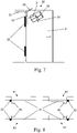
- FIG. 1 shows a door 20 with the door sensor 30 in a 3D view.
- the door 20 has a door leaf 21 which is rotatably attached to the wall 10 with door hinges 22 .
- the door leaf can be closed or opened in one direction, here in the direction of the viewer, so that the door leaf opens up the door opening 11 .
- the door hinge 20 defines the axis of rotation of the door leaf.
- the axis of rotation is the axis around which the door leaf can be moved by a certain angle of rotation. When the door is closed, the angle of rotation is assumed to be zero. When the door is fully open, the door is open at the maximum angle of rotation.
- the door 20 is a pivoting door that can be opened in only one direction.
- the door and the door leaf have two door sides.
- the first door side is the inside of the door, which is the side towards which the door opens.
- the second door side is the outside of the door, this is the side towards which the door is closed.
- a door can rotate in one of two directions.
- the direction of rotation of a door is the side on which the axis of rotation of the door is on the inside of the door.
- the direction of rotation can be clockwise or counter-clockwise.
- the door 20 has the axis of rotation on the left and therefore left-handed.
- the door sensor 30 is mounted on the door leaf 21 on the inside of the door at the top on the side of the axis of rotation on the door leaf with a very small distance (less than 20 cm or less than 10% of the width or height of the door leaf) to the top and side closure of the door leaf.
- the door sensor 30 monitors the three-dimensional monitoring field 70.
- the door sensor mounted in this way is referred to as traveling along on the door leaf.
- the monitoring field 70 also travels with the door leaf. This means that the monitoring field can be at least partially constant to the door leaf.
- the figure shows a realistic representation of the possible expansion of the surveillance field.
- the door 20 is a door that is motor-driven via a door controller, and the door sensor is designed to transmit signals to the door controller depending on its detection in the monitoring field.
- This can a Be a safety signal to stop the door, for example if a person is detected in the monitoring field in the movement field of the door leaf.
- This can also be an opening signal to open the door, for example if a person is detected in the monitoring field who is walking towards the door.
- FIG 3 shows the door sensor 30 with the housing 37 on the door leaf 21 as a detail 1 .
- the mounting plate 31 has a plane 32 for surface-parallel mounting on the door panel 21, a horizontal edge 33 for alignment parallel to the top edge of the door panel and a vertical edge 34 for alignment parallel to the side edge of the door panel.
- the mounting plate has support elements 35 for the defined angular alignment of the door sensor in relation to the plane of the door leaf.
- the mounting plate has holding elements 36 for fixing and defined angular alignment of the door sensor in relation to the horizontal and upper edge of the door leaf.
- FIG 5 also shows the door sensor 30 with the mounting plate 31 on the door leaf 21 as a detail 3 .
- the door sensor has a 3D image sensor 40 which has a transmitter 41 and a receiver 42 .
- the transmitter emits 20 MHz modulated IR radiation into the surveillance area.
- the receiver is a pixel matrix sensor which receives the radiation from the transmitter reflected from the monitoring area as an image and is designed to detect the phase shift of the modulation of the received radiation compared to the emitted radiation for each of its pixels. Due to the phase shift, the receiver determines for each of its pixels the distance of the surface in the surveillance space reflecting on this pixel and thus generates a 3D image.
- Other door sensors use the time-of-flight of the emitted radiation instead of the phase shift and reflect the radiation, which is essentially similar. These door sensors are also called TOF (Time of Flight) sensors.
- the pixels of the receiver used are also called demodulation pixels.
- the door sensor 30 in detail figure 3 .
- the support elements 35 in connection with the plane 32 of the mounting plate, fix the viewing direction and main axes of the door sensor in relation to the plane of the door leaf.
- the holding elements 36 fix in connection with the horizontal Edge 33 and the vertical edge 34 of the mounting plate the line of sight and main axes of the door sensor in relation to the horizontal and the top edge of the door leaf.
- the direction of view and main axis of the door sensor is defined by the optical axes of transmitter 41 and receiver 42 .
- FIG. 7 shows the orientation of the door sensor 30 in relation to the door leaf 21 as a detail of the previous figures.
- the coordinate system of the door leaf has its origin in the axis of rotation at the upper end of the door leaf.
- the X-axis 23 of the door panel runs horizontally in the direction of the hinge 22, the Y-axis 24 of the door panel runs perpendicular to the plane of the door panel to the outside of the door, i.e. away from the viewer, and the Z-axis 25 of the door panel runs vertically downwards.
- the coordinate system of the door sensor has its zero point in the door sensor.
- the X-axis 51 of the door sensor is rotated 30° downwards about the Y-axis of the door panel compared to the X-axis of the door panel.
- the Z-axis 53 of the door sensor is rotated 15° about the X-axis of the door sensor forward toward the viewer as compared to the plane of the door leaf.
- the Y-axis 52 of the door sensor results accordingly and points away from the viewer.
- the main viewing direction of the door sensor is therefore diagonally downwards and is pivoted forwards by 30° from the perpendicular to the outer edge of the door leaf and by 15° from the plane of the door leaf.
- the door sensor has a 3-axis gyro sensor as a rotary encoder and is not shown in the figures.
- the gyro sensor is oriented according to the coordinate system of the door sensor.
- the mounting situation 61 corresponds to the previous figures.
- the assembly situations 62, 63 and 64 do not correspond to the previous figures.
- the assembly situations 61 and 62 show the door sensor 30 on the inside of the door leaf 21
- the assembly situations 63 and 64 show the door sensor 30 on the outside of the door leaf 21
- the assembly situations 61 and 63 show the door sensor 30 on a left-turning door, since the hinges 22 are arranged on the left-hand side of the inside of the door.
- the assembly situations 62 and 64 show the door sensor 30 on a right-handed door, since the hinges 22 are arranged on the right-hand side of the inside of the door.
- Assembly situation 61 on the outside of the door a left-turning door Assembly situation 62: on the outside of the door a right-turning door Assembly situation 63: on the inside of the door a left-turning door Assembly situation 64: on the inside of the door a right-turning door
- the rotation angle sensor detects a rotation around all 3 axes when the door is opened. From this, the door sensor determines the direction of rotation around each of its axes. From the direction of rotation of the 3 axes, the door sensor now clearly determines the applicable installation situation using the following table. A positive direction of rotation in the mathematical sense is indicated here with "+”.
- the table shows that the detection of only 2 axes would be sufficient if these are the X and Y or Y and Z axes, since a clear assignment of the assembly situation is also possible with these axes alone. In this respect, it is sufficient to use a 2-axis rotary encoder for the door sensor.
- FIG 9 shows the monitoring field 71 of the door sensor 30 with the door leaf 21 closed.
- the monitoring field 71 ends at the outer edge of the door.
- the 10 shows the enlarged monitoring field 72 of the door sensor 30 with a slightly open door leaf 21 of the same door 9 .
- the monitoring field 72 now extends beyond the outer edge of the door.
- the door sensor 30 of 9 and the 10 is therefore designed to change the monitoring field as a function of the angle of rotation and to increase it here with an increasing angle of rotation.
- the door sensor can be designed so that the maximum magnification is reached at about a 45° rotation angle of the door leaf, so that the monitoring field is reduced again towards the end of the outer edge of the door when the door leaf is closed or opened by 90° or completely.
- the rotation angle for the door leaf towards the door 11, 12 and 13 is limited to a radial boundary line at 90°, for example by a floor stop, by a vertically adjoining wall, by a limitation of the door mechanism or by a limitation by the door control of the motorized door drive.
- the door leaf 11 of 11 is closed and the monitoring field 70 extends as a rectangle adjacent to the door leaf in the width of the door leaf perpendicularly into the space in front of the door leaf.
- the door leaf 11 of 12 is around 30° and the 13 opened by 60° and the monitoring field 71 extends as a rectangle adjacent to the door leaf in the width of the door leaf vertically into the space in front of the door leaf, with the monitoring field 71 on the side of the hinge of the door being reduced so that the monitoring field does not extend beyond the extends beyond the radial limit line of the maximum movement of the door leaf.
- the door sensor is designed to change the extent of the monitoring field depending on the angle of rotation of the door leaf in such a way that the monitoring field is always cut off from the plane of the door leaf at the maximum opening angle and therefore does not extend beyond this plane. In this way, for example, a wall can also be masked out so that the wall is not detected as an obstacle when the door sensor approaches.
Landscapes
- Engineering & Computer Science (AREA)
- Physics & Mathematics (AREA)
- General Physics & Mathematics (AREA)
- Radar, Positioning & Navigation (AREA)
- Remote Sensing (AREA)
- Signal Processing (AREA)
- Multimedia (AREA)
- Burglar Alarm Systems (AREA)
- Power-Operated Mechanisms For Wings (AREA)
Claims (7)
- Porte (20), en particulier porte pivotante ou porte tournante,- comprenant un vantail de porte (21), et- comprenant un capteur de porte (30) destiné au montage sur le vantail de porte (21) dans l'une des quatre situations de montage suivantes :le capteur de porte (30) étant fixé sur le vantail de porte de la porte, le capteur de porte (30) présentant• sur la face extérieure de porte dans le cas d'une porte tournant à gauche,• sur la face intérieure de porte dans le cas d'une porte tournant à gauche,• sur la face extérieure de porte dans le cas d'une porte tournant à droite, ou• sur la face intérieure de porte dans le cas d'une porte tournant à droite,• un capteur d'images 3D (40)- pour surveiller un champ de surveillance (70, 71, 72) devant le vantail de porte,• un capteur d'angle de rotation à au moins 2 axes- pour détecter l'angle de rotation du vantail de porte, et• un support commun (31)- qui relie le capteur d'images 3D au capteur d'angle de rotation,dans lequel- le support commun définit un plan de montage (32) pour le montage sur le vantail de porte, et les axes du capteur d'angle de rotation sont disposés de manière inclinée par rapport au plan de montage, et sont en particulier disposés de manière inclinée de 15°, et/ou- le support commun comprend un bord (33, 34) ou un repère pour l'alignement horizontal et/ou vertical du support sur le vantail de porte, et les axes du capteur d'angle de rotation sont disposés de manière inclinée par rapport au bord ou au repère et sont en particulier disposés de manière inclinée de 30°,caractérisée en ce que le capteur de porte (30) est adapté pour détecter une rotation autour des axes du capteur d'angle de rotation, et pour déterminer sur la base des rotations autour des axes du capteur d'angle de rotation les directions de rotation autour des axes du capteur d'angle de rotation, et pour déterminer à partir des directions de rotation la situation de montage concernée du capteur de porte (30) sur la porte.
- Porte selon la revendication 1, caractérisée- en ce que le capteur d'angle de rotation est un capteur gyroscopique.
- Porte selon l'une quelconque des revendications précédentes, caractérisée- en ce que le support commun présente une plaque de montage (31) pour le logement à position stable du capteur d'images 3D et du capteur d'angle de rotation• qui présente un plan pour le montage sur le vantail de porte, et/ou• qui comprend un bord ou un repère qui est prévu pour être disposé en alignement horizontal et/ou vertical sur le vantail de porte,• les axes du capteur d'angle de rotation étant disposés de manière simplement ou doublement inclinée par rapport aux deux axes verticaux dans le plan de montage, en particulier aux axes principaux du vantail de porte.
- Porte selon l'une quelconque des revendications précédentes, caractérisée- en ce que le capteur de porte présente un côté prédéterminé pour le montage en direction du vantail de porte.
- Porte selon l'une quelconque des revendications précédentes, caractérisée- en ce que le capteur d'angle de rotation est un capteur d'angle de rotation à 3 axes,- en particulier en ce que le capteur d'angle de rotation est un capteur gyroscopique à 3 axes.
- Porte selon l'une quelconque des revendications précédentes, caractérisée- en ce que le capteur de porte présente une mémoire pour mémoriser des paramètres environnementaux.
- Porte selon l'une quelconque des revendications précédentes, caractérisée- en ce que le capteur de porte est fixé en haut sur le vantail de porte, et/ou- sur le côté de l'axe de rotation du vantail de porte (21).
Priority Applications (3)
| Application Number | Priority Date | Filing Date | Title |
|---|---|---|---|
| EP18157281.9A EP3527954B1 (fr) | 2018-02-16 | 2018-02-16 | Capteur de porte à détecteur d'angle de rotation |
| US16/268,847 US10947768B2 (en) | 2018-02-16 | 2019-02-06 | Door sensor with rotation angle encoder |
| CN201910116010.4A CN110160485B (zh) | 2018-02-16 | 2019-02-15 | 具有转动角度编码器的门传感器 |
Applications Claiming Priority (1)
| Application Number | Priority Date | Filing Date | Title |
|---|---|---|---|
| EP18157281.9A EP3527954B1 (fr) | 2018-02-16 | 2018-02-16 | Capteur de porte à détecteur d'angle de rotation |
Publications (2)
| Publication Number | Publication Date |
|---|---|
| EP3527954A1 EP3527954A1 (fr) | 2019-08-21 |
| EP3527954B1 true EP3527954B1 (fr) | 2022-03-30 |
Family
ID=61231191
Family Applications (1)
| Application Number | Title | Priority Date | Filing Date |
|---|---|---|---|
| EP18157281.9A Active EP3527954B1 (fr) | 2018-02-16 | 2018-02-16 | Capteur de porte à détecteur d'angle de rotation |
Country Status (3)
| Country | Link |
|---|---|
| US (1) | US10947768B2 (fr) |
| EP (1) | EP3527954B1 (fr) |
| CN (1) | CN110160485B (fr) |
Families Citing this family (11)
| Publication number | Priority date | Publication date | Assignee | Title |
|---|---|---|---|---|
| US10808447B2 (en) | 2017-04-25 | 2020-10-20 | Masonite Corporation | Emergency door closing device |
| DE102018203813A1 (de) * | 2018-03-13 | 2019-09-19 | Pepperl + Fuchs Gmbh | Türsensoreinrichtung und verfahren zum betreiben einer türsensoreinrichtung |
| US11174664B2 (en) | 2018-03-20 | 2021-11-16 | Masonite Corporation | Door positioning system |
| US11396975B2 (en) | 2019-07-08 | 2022-07-26 | Rick Hagel | Removable or adjustable cover for garage door sensor |
| US11125004B2 (en) * | 2019-07-08 | 2021-09-21 | Rick Hagel | Removable or adjustable cover for garage door sensor |
| JP1677183S (fr) | 2019-10-31 | 2021-01-18 | ||
| CN113266994B (zh) * | 2020-02-17 | 2022-10-25 | 青岛海尔电冰箱有限公司 | 冰箱及冰箱检测方法 |
| CN111577059B (zh) * | 2020-04-17 | 2021-09-28 | 佛山科学技术学院 | 基于数字陀螺仪的门开关检测系统 |
| CN111491085B (zh) * | 2020-04-21 | 2021-11-05 | Oppo广东移动通信有限公司 | 图像传感器、摄像装置及电子设备 |
| DE102020205810A1 (de) * | 2020-05-08 | 2021-11-11 | Geze Gmbh | Automatische Fensteranlage |
| CN113878614B (zh) * | 2021-09-27 | 2024-05-24 | 山东新一代信息产业技术研究院有限公司 | 一种增加室外巡检机器人重心平衡的方法及系统 |
Citations (1)
| Publication number | Priority date | Publication date | Assignee | Title |
|---|---|---|---|---|
| US20120127317A1 (en) * | 2010-11-19 | 2012-05-24 | Bea, Inc. | Method and device to securely open and close a passageway or access point |
Family Cites Families (16)
| Publication number | Priority date | Publication date | Assignee | Title |
|---|---|---|---|---|
| JP3855234B2 (ja) * | 2002-07-09 | 2006-12-06 | オプテックス株式会社 | ドアセンサ及びそのドアセンサを備えたドア |
| ATE387620T1 (de) * | 2004-07-22 | 2008-03-15 | Bea Sa | Lichtabtastvorrichtung zur detektion um automatische türen |
| JP4915246B2 (ja) * | 2007-01-26 | 2012-04-11 | セイコーエプソン株式会社 | ジャイロモジュール |
| DE102007038421B8 (de) * | 2007-08-14 | 2008-12-24 | Pepperl + Fuchs Gmbh | Sicherheitsvorrichtung und Verfahren zum Überwachen einer automatischen Tür |
| DE102009024601A1 (de) * | 2008-10-23 | 2010-04-29 | Pepperl + Fuchs Gmbh | Türüberwachungssensor und Verfahren zum Betrieb eines Türüberwachungssensors |
| JP4904552B1 (ja) * | 2010-10-29 | 2012-03-28 | オプテックス株式会社 | 自動ドアセンサーおよびそれに用いられる機能拡張モジュール |
| EP2667218B1 (fr) | 2010-11-15 | 2017-10-18 | Cedes AG | Capteur 3D à économie d'énergie |
| DK2453254T3 (da) | 2010-11-15 | 2013-04-08 | Cedes Ag | Indretning til overvågning af en dør med en 3D-sensor |
| EP2453260B2 (fr) | 2010-11-15 | 2024-01-31 | Cedes AG | Capteur de surveillance doté d'un contrôle automatique |
| WO2012071664A1 (fr) | 2010-12-03 | 2012-06-07 | Sensotech Inc. | Système de détection d'ultrasons adaptatif pour ensemble porte |
| US9329035B2 (en) * | 2011-12-12 | 2016-05-03 | Heptagon Micro Optics Pte. Ltd. | Method to compensate for errors in time-of-flight range cameras caused by multiple reflections |
| GB2511069B (en) * | 2013-02-21 | 2015-06-17 | Dale Read | Energy usage monitoring system |
| DE102013221494A1 (de) * | 2013-10-23 | 2015-04-23 | Robert Bosch Gmbh | Verfahren und Vorrichtung zum Bestimmen eines Drehwinkels eines Objekts um eine Drehachse |
| US9217272B2 (en) * | 2013-11-12 | 2015-12-22 | Complete Entry Systems and Services (2004) Inc. | Automatic door with emergency rescue system |
| US11136812B2 (en) * | 2016-05-09 | 2021-10-05 | Milbat—Giving Quality to Life | Motorized door opening device |
| US10551407B2 (en) * | 2016-07-29 | 2020-02-04 | Blackberry Limited | Determining an open/close status of a barrier |
-
2018
- 2018-02-16 EP EP18157281.9A patent/EP3527954B1/fr active Active
-
2019
- 2019-02-06 US US16/268,847 patent/US10947768B2/en active Active
- 2019-02-15 CN CN201910116010.4A patent/CN110160485B/zh active Active
Patent Citations (1)
| Publication number | Priority date | Publication date | Assignee | Title |
|---|---|---|---|---|
| US20120127317A1 (en) * | 2010-11-19 | 2012-05-24 | Bea, Inc. | Method and device to securely open and close a passageway or access point |
Also Published As
| Publication number | Publication date |
|---|---|
| US10947768B2 (en) | 2021-03-16 |
| US20190257130A1 (en) | 2019-08-22 |
| CN110160485A (zh) | 2019-08-23 |
| EP3527954A1 (fr) | 2019-08-21 |
| CN110160485B (zh) | 2023-06-06 |
Similar Documents
| Publication | Publication Date | Title |
|---|---|---|
| EP3527954B1 (fr) | Capteur de porte à détecteur d'angle de rotation | |
| EP3527766B1 (fr) | Procédé de configurationd'un capteur de porte | |
| EP2640607B1 (fr) | Dispositif comprenant un ensemble caméra et un élément de protection à courbe de déplacement compacte | |
| DE102007050334A1 (de) | Verfahren und Einrichtung zur Steuerung eines vertikal oder horizontal bewegten Tores unter Absicherung der Torschließebene gegenüber Hindernissen | |
| EP1470314B1 (fr) | Porte avec actionnement automatique, notamment porte relevable, et methode pour son actionnement | |
| DE10245889B4 (de) | Verfahren und/oder Einrichtung zur Bestimmung einer Pendelung einer Last eines Hebezeuges | |
| DE102011053212B3 (de) | Optoelektronischer Sensor und Verfahren zur Erfassung von Objekten in einem Überwachungsbereich | |
| DE102015213694A1 (de) | Sensorsystem zum Erkennen überstehender oder freiliegender Objekte in der Umgebung eines Fahrzeugs | |
| WO1992002831A1 (fr) | Systeme de surveillance aux ultra-sons de l'habitacle d'un vehicule a moteur | |
| EP3581747B1 (fr) | Dispositif de surveillance | |
| DE19653026B4 (de) | Vorrichtung zur Ansteuerung und/oder Absicherung eines motorisch angetriebenen Flügels einer Tür, eines Fensters oder dergleichen | |
| DE102008044990A1 (de) | Verfahren und Vorrichtung zur Ansteuerung und/oder Überwachung eines motorisch angetriebenen Flügels während der Öffnungsphase | |
| DE102018114552A1 (de) | Schutzvorrichtung und Verfahren zum Betreiben einer Schutzvorrichtung | |
| EP2335229B1 (fr) | Système de sécurité contre le déplacement pour caméras de surveillance | |
| EP3575534A1 (fr) | Dispositif de sécurisation sensorielle des mouvements de battant d'une porte tournante automatique | |
| DE3344576C1 (de) | Sensoranordnung zur Überwachung des Schwenkbereiches von Türflügeln | |
| DE3744399C2 (de) | Strahlungsempfindlicher Schalter | |
| DE19953006A1 (de) | Vorrichtung zur Steuerung des Verkehrsflusses im Bereich einer Kreuzung, insbesondere zur Ampelsteuerung | |
| DE102013212518B4 (de) | Automatische Fenster- oder Türanlage | |
| DE19804632C2 (de) | Verfahren und Vorrichtung zur Ansteuerung und/oder Überwachung eines motorisch angetriebenen Flügels | |
| EP3521860B1 (fr) | Dispositif capteur optoélectronique | |
| DE2548465A1 (de) | Tuersicherungs-lichtschranke | |
| DE19804631C2 (de) | Verfahren und Vorrichtung zur Ansteuerung und/oder Überwachung eines motorisch angetriebenen Flügels | |
| DE29701462U1 (de) | Vorrichtung zur automatischen Steuerung von Toren oder Türen | |
| EP0852313A1 (fr) | Dispositif pour la commande et/ou pour sécuriser les panneaux de portes motorisés, fenêtres ou analogues |
Legal Events
| Date | Code | Title | Description |
|---|---|---|---|
| PUAI | Public reference made under article 153(3) epc to a published international application that has entered the european phase |
Free format text: ORIGINAL CODE: 0009012 |
|
| STAA | Information on the status of an ep patent application or granted ep patent |
Free format text: STATUS: REQUEST FOR EXAMINATION WAS MADE |
|
| 17P | Request for examination filed |
Effective date: 20190702 |
|
| AK | Designated contracting states |
Kind code of ref document: A1 Designated state(s): AL AT BE BG CH CY CZ DE DK EE ES FI FR GB GR HR HU IE IS IT LI LT LU LV MC MK MT NL NO PL PT RO RS SE SI SK SM TR |
|
| AX | Request for extension of the european patent |
Extension state: BA ME |
|
| STAA | Information on the status of an ep patent application or granted ep patent |
Free format text: STATUS: EXAMINATION IS IN PROGRESS |
|
| 17Q | First examination report despatched |
Effective date: 20201020 |
|
| GRAP | Despatch of communication of intention to grant a patent |
Free format text: ORIGINAL CODE: EPIDOSNIGR1 |
|
| STAA | Information on the status of an ep patent application or granted ep patent |
Free format text: STATUS: GRANT OF PATENT IS INTENDED |
|
| INTG | Intention to grant announced |
Effective date: 20211022 |
|
| GRAS | Grant fee paid |
Free format text: ORIGINAL CODE: EPIDOSNIGR3 |
|
| GRAA | (expected) grant |
Free format text: ORIGINAL CODE: 0009210 |
|
| STAA | Information on the status of an ep patent application or granted ep patent |
Free format text: STATUS: THE PATENT HAS BEEN GRANTED |
|
| AK | Designated contracting states |
Kind code of ref document: B1 Designated state(s): AL AT BE BG CH CY CZ DE DK EE ES FI FR GB GR HR HU IE IS IT LI LT LU LV MC MK MT NL NO PL PT RO RS SE SI SK SM TR |
|
| REG | Reference to a national code |
Ref country code: GB Ref legal event code: FG4D Free format text: NOT ENGLISH |
|
| REG | Reference to a national code |
Ref country code: CH Ref legal event code: EP |
|
| REG | Reference to a national code |
Ref country code: AT Ref legal event code: REF Ref document number: 1479599 Country of ref document: AT Kind code of ref document: T Effective date: 20220415 |
|
| REG | Reference to a national code |
Ref country code: DE Ref legal event code: R096 Ref document number: 502018009209 Country of ref document: DE |
|
| REG | Reference to a national code |
Ref country code: IE Ref legal event code: FG4D Free format text: LANGUAGE OF EP DOCUMENT: GERMAN |
|
| REG | Reference to a national code |
Ref country code: LT Ref legal event code: MG9D |
|
| PG25 | Lapsed in a contracting state [announced via postgrant information from national office to epo] |
Ref country code: SE Free format text: LAPSE BECAUSE OF FAILURE TO SUBMIT A TRANSLATION OF THE DESCRIPTION OR TO PAY THE FEE WITHIN THE PRESCRIBED TIME-LIMIT Effective date: 20220330 Ref country code: RS Free format text: LAPSE BECAUSE OF FAILURE TO SUBMIT A TRANSLATION OF THE DESCRIPTION OR TO PAY THE FEE WITHIN THE PRESCRIBED TIME-LIMIT Effective date: 20220330 Ref country code: NO Free format text: LAPSE BECAUSE OF FAILURE TO SUBMIT A TRANSLATION OF THE DESCRIPTION OR TO PAY THE FEE WITHIN THE PRESCRIBED TIME-LIMIT Effective date: 20220630 Ref country code: LT Free format text: LAPSE BECAUSE OF FAILURE TO SUBMIT A TRANSLATION OF THE DESCRIPTION OR TO PAY THE FEE WITHIN THE PRESCRIBED TIME-LIMIT Effective date: 20220330 Ref country code: HR Free format text: LAPSE BECAUSE OF FAILURE TO SUBMIT A TRANSLATION OF THE DESCRIPTION OR TO PAY THE FEE WITHIN THE PRESCRIBED TIME-LIMIT Effective date: 20220330 Ref country code: BG Free format text: LAPSE BECAUSE OF FAILURE TO SUBMIT A TRANSLATION OF THE DESCRIPTION OR TO PAY THE FEE WITHIN THE PRESCRIBED TIME-LIMIT Effective date: 20220630 |
|
| REG | Reference to a national code |
Ref country code: NL Ref legal event code: MP Effective date: 20220330 |
|
| PG25 | Lapsed in a contracting state [announced via postgrant information from national office to epo] |
Ref country code: LV Free format text: LAPSE BECAUSE OF FAILURE TO SUBMIT A TRANSLATION OF THE DESCRIPTION OR TO PAY THE FEE WITHIN THE PRESCRIBED TIME-LIMIT Effective date: 20220330 Ref country code: GR Free format text: LAPSE BECAUSE OF FAILURE TO SUBMIT A TRANSLATION OF THE DESCRIPTION OR TO PAY THE FEE WITHIN THE PRESCRIBED TIME-LIMIT Effective date: 20220701 Ref country code: FI Free format text: LAPSE BECAUSE OF FAILURE TO SUBMIT A TRANSLATION OF THE DESCRIPTION OR TO PAY THE FEE WITHIN THE PRESCRIBED TIME-LIMIT Effective date: 20220330 |
|
| PG25 | Lapsed in a contracting state [announced via postgrant information from national office to epo] |
Ref country code: NL Free format text: LAPSE BECAUSE OF FAILURE TO SUBMIT A TRANSLATION OF THE DESCRIPTION OR TO PAY THE FEE WITHIN THE PRESCRIBED TIME-LIMIT Effective date: 20220330 |
|
| PG25 | Lapsed in a contracting state [announced via postgrant information from national office to epo] |
Ref country code: SM Free format text: LAPSE BECAUSE OF FAILURE TO SUBMIT A TRANSLATION OF THE DESCRIPTION OR TO PAY THE FEE WITHIN THE PRESCRIBED TIME-LIMIT Effective date: 20220330 Ref country code: SK Free format text: LAPSE BECAUSE OF FAILURE TO SUBMIT A TRANSLATION OF THE DESCRIPTION OR TO PAY THE FEE WITHIN THE PRESCRIBED TIME-LIMIT Effective date: 20220330 Ref country code: RO Free format text: LAPSE BECAUSE OF FAILURE TO SUBMIT A TRANSLATION OF THE DESCRIPTION OR TO PAY THE FEE WITHIN THE PRESCRIBED TIME-LIMIT Effective date: 20220330 Ref country code: PT Free format text: LAPSE BECAUSE OF FAILURE TO SUBMIT A TRANSLATION OF THE DESCRIPTION OR TO PAY THE FEE WITHIN THE PRESCRIBED TIME-LIMIT Effective date: 20220801 Ref country code: ES Free format text: LAPSE BECAUSE OF FAILURE TO SUBMIT A TRANSLATION OF THE DESCRIPTION OR TO PAY THE FEE WITHIN THE PRESCRIBED TIME-LIMIT Effective date: 20220330 Ref country code: EE Free format text: LAPSE BECAUSE OF FAILURE TO SUBMIT A TRANSLATION OF THE DESCRIPTION OR TO PAY THE FEE WITHIN THE PRESCRIBED TIME-LIMIT Effective date: 20220330 Ref country code: CZ Free format text: LAPSE BECAUSE OF FAILURE TO SUBMIT A TRANSLATION OF THE DESCRIPTION OR TO PAY THE FEE WITHIN THE PRESCRIBED TIME-LIMIT Effective date: 20220330 |
|
| PG25 | Lapsed in a contracting state [announced via postgrant information from national office to epo] |
Ref country code: PL Free format text: LAPSE BECAUSE OF FAILURE TO SUBMIT A TRANSLATION OF THE DESCRIPTION OR TO PAY THE FEE WITHIN THE PRESCRIBED TIME-LIMIT Effective date: 20220330 Ref country code: IS Free format text: LAPSE BECAUSE OF FAILURE TO SUBMIT A TRANSLATION OF THE DESCRIPTION OR TO PAY THE FEE WITHIN THE PRESCRIBED TIME-LIMIT Effective date: 20220730 Ref country code: AL Free format text: LAPSE BECAUSE OF FAILURE TO SUBMIT A TRANSLATION OF THE DESCRIPTION OR TO PAY THE FEE WITHIN THE PRESCRIBED TIME-LIMIT Effective date: 20220330 |
|
| REG | Reference to a national code |
Ref country code: DE Ref legal event code: R097 Ref document number: 502018009209 Country of ref document: DE |
|
| PG25 | Lapsed in a contracting state [announced via postgrant information from national office to epo] |
Ref country code: DK Free format text: LAPSE BECAUSE OF FAILURE TO SUBMIT A TRANSLATION OF THE DESCRIPTION OR TO PAY THE FEE WITHIN THE PRESCRIBED TIME-LIMIT Effective date: 20220330 |
|
| PLBE | No opposition filed within time limit |
Free format text: ORIGINAL CODE: 0009261 |
|
| STAA | Information on the status of an ep patent application or granted ep patent |
Free format text: STATUS: NO OPPOSITION FILED WITHIN TIME LIMIT |
|
| 26N | No opposition filed |
Effective date: 20230103 |
|
| PG25 | Lapsed in a contracting state [announced via postgrant information from national office to epo] |
Ref country code: SI Free format text: LAPSE BECAUSE OF FAILURE TO SUBMIT A TRANSLATION OF THE DESCRIPTION OR TO PAY THE FEE WITHIN THE PRESCRIBED TIME-LIMIT Effective date: 20220330 |
|
| P01 | Opt-out of the competence of the unified patent court (upc) registered |
Effective date: 20230519 |
|
| PG25 | Lapsed in a contracting state [announced via postgrant information from national office to epo] |
Ref country code: IT Free format text: LAPSE BECAUSE OF FAILURE TO SUBMIT A TRANSLATION OF THE DESCRIPTION OR TO PAY THE FEE WITHIN THE PRESCRIBED TIME-LIMIT Effective date: 20220330 |
|
| PG25 | Lapsed in a contracting state [announced via postgrant information from national office to epo] |
Ref country code: MC Free format text: LAPSE BECAUSE OF FAILURE TO SUBMIT A TRANSLATION OF THE DESCRIPTION OR TO PAY THE FEE WITHIN THE PRESCRIBED TIME-LIMIT Effective date: 20220330 |
|
| GBPC | Gb: european patent ceased through non-payment of renewal fee |
Effective date: 20230216 |
|
| PG25 | Lapsed in a contracting state [announced via postgrant information from national office to epo] |
Ref country code: LU Free format text: LAPSE BECAUSE OF NON-PAYMENT OF DUE FEES Effective date: 20230216 |
|
| REG | Reference to a national code |
Ref country code: IE Ref legal event code: MM4A |
|
| PG25 | Lapsed in a contracting state [announced via postgrant information from national office to epo] |
Ref country code: GB Free format text: LAPSE BECAUSE OF NON-PAYMENT OF DUE FEES Effective date: 20230216 |
|
| PG25 | Lapsed in a contracting state [announced via postgrant information from national office to epo] |
Ref country code: IE Free format text: LAPSE BECAUSE OF NON-PAYMENT OF DUE FEES Effective date: 20230216 Ref country code: GB Free format text: LAPSE BECAUSE OF NON-PAYMENT OF DUE FEES Effective date: 20230216 Ref country code: FR Free format text: LAPSE BECAUSE OF NON-PAYMENT OF DUE FEES Effective date: 20230228 |
|
| REG | Reference to a national code |
Ref country code: AT Ref legal event code: MM01 Ref document number: 1479599 Country of ref document: AT Kind code of ref document: T Effective date: 20230216 |
|
| PG25 | Lapsed in a contracting state [announced via postgrant information from national office to epo] |
Ref country code: AT Free format text: LAPSE BECAUSE OF NON-PAYMENT OF DUE FEES Effective date: 20230216 |
|
| PG25 | Lapsed in a contracting state [announced via postgrant information from national office to epo] |
Ref country code: AT Free format text: LAPSE BECAUSE OF NON-PAYMENT OF DUE FEES Effective date: 20230216 |
|
| REG | Reference to a national code |
Ref country code: DE Ref legal event code: R082 Ref document number: 502018009209 Country of ref document: DE Representative=s name: RAVENSPAT PATENTANWAELTE PARTNERSCHAFT MBB, DE |
|
| PG25 | Lapsed in a contracting state [announced via postgrant information from national office to epo] |
Ref country code: CY Free format text: LAPSE BECAUSE OF FAILURE TO SUBMIT A TRANSLATION OF THE DESCRIPTION OR TO PAY THE FEE WITHIN THE PRESCRIBED TIME-LIMIT; INVALID AB INITIO Effective date: 20180216 |
|
| PG25 | Lapsed in a contracting state [announced via postgrant information from national office to epo] |
Ref country code: HU Free format text: LAPSE BECAUSE OF FAILURE TO SUBMIT A TRANSLATION OF THE DESCRIPTION OR TO PAY THE FEE WITHIN THE PRESCRIBED TIME-LIMIT; INVALID AB INITIO Effective date: 20180216 |
|
| PG25 | Lapsed in a contracting state [announced via postgrant information from national office to epo] |
Ref country code: TR Free format text: LAPSE BECAUSE OF FAILURE TO SUBMIT A TRANSLATION OF THE DESCRIPTION OR TO PAY THE FEE WITHIN THE PRESCRIBED TIME-LIMIT Effective date: 20220330 |
|
| REG | Reference to a national code |
Ref country code: CH Ref legal event code: U11 Free format text: ST27 STATUS EVENT CODE: U-0-0-U10-U11 (AS PROVIDED BY THE NATIONAL OFFICE) Effective date: 20260301 |
|
| PGFP | Annual fee paid to national office [announced via postgrant information from national office to epo] |
Ref country code: DE Payment date: 20260217 Year of fee payment: 9 |
|
| PGFP | Annual fee paid to national office [announced via postgrant information from national office to epo] |
Ref country code: BE Payment date: 20260218 Year of fee payment: 9 |
|
| PGFP | Annual fee paid to national office [announced via postgrant information from national office to epo] |
Ref country code: CH Payment date: 20260301 Year of fee payment: 9 |