EP3528342A1 - Système d'antenne, et procédé et appareil de mappage d'accès d'antenne virtuelle - Google Patents
Système d'antenne, et procédé et appareil de mappage d'accès d'antenne virtuelle Download PDFInfo
- Publication number
- EP3528342A1 EP3528342A1 EP16921862.5A EP16921862A EP3528342A1 EP 3528342 A1 EP3528342 A1 EP 3528342A1 EP 16921862 A EP16921862 A EP 16921862A EP 3528342 A1 EP3528342 A1 EP 3528342A1
- Authority
- EP
- European Patent Office
- Prior art keywords
- antenna
- port
- module
- physical
- virtual
- Prior art date
- Legal status (The legal status is an assumption and is not a legal conclusion. Google has not performed a legal analysis and makes no representation as to the accuracy of the status listed.)
- Withdrawn
Links
- 238000013507 mapping Methods 0.000 title claims abstract description 80
- 238000000034 method Methods 0.000 title claims abstract description 56
- 238000004891 communication Methods 0.000 claims abstract description 9
- 238000012545 processing Methods 0.000 claims description 36
- 238000005516 engineering process Methods 0.000 abstract description 4
- 238000010586 diagram Methods 0.000 description 34
- 238000013461 design Methods 0.000 description 31
- 238000003491 array Methods 0.000 description 14
- 230000006870 function Effects 0.000 description 10
- 238000004590 computer program Methods 0.000 description 8
- 230000005540 biological transmission Effects 0.000 description 6
- 230000000694 effects Effects 0.000 description 6
- 238000012544 monitoring process Methods 0.000 description 5
- 230000009286 beneficial effect Effects 0.000 description 4
- 238000012986 modification Methods 0.000 description 4
- 230000004048 modification Effects 0.000 description 4
- 230000003287 optical effect Effects 0.000 description 3
- 230000002093 peripheral effect Effects 0.000 description 2
- 230000003068 static effect Effects 0.000 description 2
- 230000001427 coherent effect Effects 0.000 description 1
- 238000010276 construction Methods 0.000 description 1
- 230000001419 dependent effect Effects 0.000 description 1
- 238000011161 development Methods 0.000 description 1
- 238000000802 evaporation-induced self-assembly Methods 0.000 description 1
- 238000009434 installation Methods 0.000 description 1
- 238000012423 maintenance Methods 0.000 description 1
- 239000013307 optical fiber Substances 0.000 description 1
- 230000011664 signaling Effects 0.000 description 1
- 238000004088 simulation Methods 0.000 description 1
Images







Classifications
-
- H—ELECTRICITY
- H01—ELECTRIC ELEMENTS
- H01Q—ANTENNAS, i.e. RADIO AERIALS
- H01Q1/00—Details of, or arrangements associated with, antennas
- H01Q1/12—Supports; Mounting means
- H01Q1/22—Supports; Mounting means by structural association with other equipment or articles
- H01Q1/24—Supports; Mounting means by structural association with other equipment or articles with receiving set
- H01Q1/241—Supports; Mounting means by structural association with other equipment or articles with receiving set used in mobile communications, e.g. GSM
- H01Q1/246—Supports; Mounting means by structural association with other equipment or articles with receiving set used in mobile communications, e.g. GSM specially adapted for base stations
-
- H—ELECTRICITY
- H04—ELECTRIC COMMUNICATION TECHNIQUE
- H04B—TRANSMISSION
- H04B7/00—Radio transmission systems, i.e. using radiation field
- H04B7/02—Diversity systems; Multi-antenna system, i.e. transmission or reception using multiple antennas
- H04B7/04—Diversity systems; Multi-antenna system, i.e. transmission or reception using multiple antennas using two or more spaced independent antennas
- H04B7/06—Diversity systems; Multi-antenna system, i.e. transmission or reception using multiple antennas using two or more spaced independent antennas at the transmitting station
- H04B7/0613—Diversity systems; Multi-antenna system, i.e. transmission or reception using multiple antennas using two or more spaced independent antennas at the transmitting station using simultaneous transmission
- H04B7/0615—Diversity systems; Multi-antenna system, i.e. transmission or reception using multiple antennas using two or more spaced independent antennas at the transmitting station using simultaneous transmission of weighted versions of same signal
- H04B7/0617—Diversity systems; Multi-antenna system, i.e. transmission or reception using multiple antennas using two or more spaced independent antennas at the transmitting station using simultaneous transmission of weighted versions of same signal for beam forming
-
- H—ELECTRICITY
- H01—ELECTRIC ELEMENTS
- H01Q—ANTENNAS, i.e. RADIO AERIALS
- H01Q21/00—Antenna arrays or systems
-
- H—ELECTRICITY
- H01—ELECTRIC ELEMENTS
- H01Q—ANTENNAS, i.e. RADIO AERIALS
- H01Q21/00—Antenna arrays or systems
- H01Q21/24—Combinations of antenna units polarised in different directions for transmitting or receiving circularly and elliptically polarised waves or waves linearly polarised in any direction
-
- H—ELECTRICITY
- H01—ELECTRIC ELEMENTS
- H01Q—ANTENNAS, i.e. RADIO AERIALS
- H01Q21/00—Antenna arrays or systems
- H01Q21/24—Combinations of antenna units polarised in different directions for transmitting or receiving circularly and elliptically polarised waves or waves linearly polarised in any direction
- H01Q21/26—Turnstile or like antennas comprising arrangements of three or more elongated elements disposed radially and symmetrically in a horizontal plane about a common centre
-
- H—ELECTRICITY
- H01—ELECTRIC ELEMENTS
- H01Q—ANTENNAS, i.e. RADIO AERIALS
- H01Q21/00—Antenna arrays or systems
- H01Q21/28—Combinations of substantially independent non-interacting antenna units or systems
-
- H—ELECTRICITY
- H01—ELECTRIC ELEMENTS
- H01Q—ANTENNAS, i.e. RADIO AERIALS
- H01Q25/00—Antennas or antenna systems providing at least two radiating patterns
- H01Q25/001—Crossed polarisation dual antennas
-
- H—ELECTRICITY
- H01—ELECTRIC ELEMENTS
- H01Q—ANTENNAS, i.e. RADIO AERIALS
- H01Q25/00—Antennas or antenna systems providing at least two radiating patterns
- H01Q25/02—Antennas or antenna systems providing at least two radiating patterns providing sum and difference patterns
-
- H—ELECTRICITY
- H01—ELECTRIC ELEMENTS
- H01Q—ANTENNAS, i.e. RADIO AERIALS
- H01Q3/00—Arrangements for changing or varying the orientation or the shape of the directional pattern of the waves radiated from an antenna or antenna system
- H01Q3/26—Arrangements for changing or varying the orientation or the shape of the directional pattern of the waves radiated from an antenna or antenna system varying the relative phase or relative amplitude of energisation between two or more active radiating elements; varying the distribution of energy across a radiating aperture
-
- H—ELECTRICITY
- H04—ELECTRIC COMMUNICATION TECHNIQUE
- H04B—TRANSMISSION
- H04B7/00—Radio transmission systems, i.e. using radiation field
Definitions
- the present invention relates to the field of communications technologies, and in particular, to an antenna system, a virtual antenna port mapping method, and an apparatus.
- a micro base station is characterized by a large capacity and a high rate, so that a network capacity can be increased, and a user Internet access rate in an edge coverage area of a macro base station can be increased.
- the micro base station can also adapt to various backhaul networks, and can be deployed flexibly and quickly, to bring better mobile broadband experience to a user.
- the micro base station implements network coverage in Manner 1
- the macro base station implements network coverage in Manner 2.
- an antenna system of the micro base station includes an antenna array, the antenna array includes six longitudinally-arranged antenna array elements, and each antenna array element includes one positive-45-degree polarized array element and one negative-45-degree polarized array element.
- Six positive-45-degree polarized array elements correspond to a physical antenna port 0, and six negative-45-degree polarized array elements correspond to a physical antenna port 1.
- a baseband processing unit (Baseband Unit, BBU for short) in the micro base station respectively maps a virtual antenna port 0 (Port 0) and a virtual antenna port 1 (Port 1) to the physical antenna port 0 and the physical antenna port 1 by using a weighted value [1, 1], so that the antenna system generates a beam in a fixed shape through the mapping, thereby implementing network coverage.
- BBU Baseband Unit
- an antenna system of the macro base station includes an antenna array, the antenna array includes two columns of antenna array elements, each column includes six longitudinally-arranged antenna array elements, and each antenna array element includes one positive-45-degree polarized array element and one negative-45-degree polarized array element.
- Six positive-45-degree polarized array elements of antenna array elements in a first column correspond to a physical antenna port 0, six negative-45-degree polarized array elements of the antenna array elements in the first column correspond to a physical antenna port 1, six positive-45-degree polarized array elements of antenna array elements in a second column correspond to a physical antenna port 2, and six negative-45-degree polarized array elements of the antenna array elements in the second column correspond to a physical antenna port 3.
- a BBU in the macro base station maps a virtual antenna port 0 (Port 0) to the physical antenna port 0 and the physical antenna port 1, and maps a virtual antenna port 1 (Port 1) to the physical antenna port 2 and the physical antenna port 3, so that the antenna system generates a beam in a fixed shape through the mapping, thereby implementing network coverage.
- Manner 1 may be applied only to a low-rise residential area and street coverage scenario, and a main installation manner is installing the antenna system on a body of a pole on a street.
- Manner 2 is applied to a wide coverage scenario in which buildings are not densely packed. Because a radio remote unit (Radio Remote Unit, RRU for short) and the antenna system of the macro base station are relatively large in volume and weight, Manner 2 cannot be applied to the low-rise residential area and street coverage scenario.
- RRU Radio Remote Unit
- Embodiments of the present invention provide an antenna system, a virtual antenna port mapping method, and an apparatus, to implement network coverage on a mid- or high-rise building.
- an antenna system includes: at least one antenna module, where the antenna module includes a longitudinally-arranged first antenna array and a longitudinally-arranged second antenna array; and at least one electrical adjustment group in a one-to-one correspondence with the at least one antenna module, where the electrical adjustment group includes a first electrical adjustment and a second electrical adjustment; the first electrical adjustment in the electrical adjustment group corresponding to each antenna module is connected to the first antenna array in the antenna module, and is configured to adjust a downtilt angle of a vertical lobe of a beam generated by the first antenna array in the antenna module; and the second electrical adjustment in the electrical adjustment group corresponding to each antenna module is connected to the second antenna array in the antenna module, and is configured to adjust a downtilt angle of a vertical lobe of a beam generated by the second antenna array in the antenna module.
- the antenna system provided in the first aspect includes at least two antenna arrays. Therefore, at least two beams can be generated, and directions of the two beams can be controlled by using an electrical adjustment, so that the two beams jointly form a vertical-dimension wide beam (or narrow beam), to implement network coverage on a high-rise building (or a low-rise building).
- the first antenna array in the antenna module includes N1 longitudinally-arranged antenna array elements
- the second antenna array in the antenna module includes N2 longitudinally-arranged antenna array elements
- each antenna array element includes one positive-45-degree polarized array element and one negative-45-degree polarized array element
- N1 positive-45-degree polarized array elements of the first antenna array correspond to a third physical antenna port
- N1 negative-45-degree polarized array elements of the first antenna array correspond to a fourth physical antenna port
- N2 positive-45-degree polarized array elements of the second antenna array correspond to a first physical antenna port
- N2 negative-45-degree polarized array elements of the second antenna array correspond to a second physical antenna port
- both N1 and N2 are integers greater than 0.
- a virtual antenna port mapping method includes: obtaining, by a baseband processing unit BBU, architecture information of an antenna system, where the antenna system includes at least one antenna module, the antenna module includes a longitudinally-arranged first antenna array and a longitudinally-arranged second antenna array, and a downtilt angle of a vertical lobe of a beam generated by the first antenna array is the same as or different from a downtilt angle of a vertical lobe of a beam generated by the second antenna array; and mapping, by the BBU, a virtual antenna port of the BBU to a physical antenna port in the antenna system based on the architecture information of the antenna system and the virtual antenna port.
- the virtual antenna port may be mapped to the physical antenna port, so that the antenna module can generate a combined beam. Because the downtilt angles of the vertical lobes of the two beams that are generated by the two antenna arrays and that form the combined beam may be different, the combined beam may be a vertical-dimension wide beam, to implement network coverage on a high-rise building.
- the first antenna array in the antenna module includes N1 longitudinally-arranged antenna array elements
- the second antenna array in the antenna module includes N2 longitudinally-arranged antenna array elements
- each antenna array element includes one positive-45-degree polarized array element and one negative-45-degree polarized array element
- N1 positive-45-degree polarized array elements of the first antenna array correspond to a third physical antenna port
- N1 negative-45-degree polarized array elements of the first antenna array correspond to a fourth physical antenna port
- N2 positive-45-degree polarized array elements of the second antenna array correspond to a first physical antenna port
- N2 negative-45-degree polarized array elements of the second antenna array correspond to a second physical antenna port
- both N1 and N2 are integers greater than 0.
- the antenna system includes one antenna module, a downtilt angle of a vertical lobe of a beam generated by a first antenna array in the antenna module is the same as a downtilt angle of a vertical lobe of a beam generated by a second antenna array in the antenna module, there are two virtual antenna ports, and the mapping, by the BBU, a virtual antenna port of the BBU to a physical antenna port in the antenna system based on the architecture information of the antenna system and the virtual antenna port includes: mapping, by the BBU, a virtual antenna port 0 in the two virtual antenna ports to a first physical antenna port and a third physical antenna port in the antenna module by using a weighted value [1, 1], and mapping a virtual antenna port 1 in the two virtual antenna ports to a second physical antenna port and a fourth physical antenna port in the antenna module by using a weighted value [1, 1].
- a combined beam of the antenna module is a vertical-dimension narrow beam, and the narrow beam may perform network coverage on a low-rise building and a street.
- the antenna system includes one antenna module, a downtilt angle of a vertical lobe of a beam generated by a first antenna array in the antenna module is different from a downtilt angle of a vertical lobe of a beam generated by a second antenna array in the antenna module, there are two virtual antenna ports, and the mapping, by the BBU, a virtual antenna port of the BBU to a physical antenna port in the antenna system based on the architecture information of the antenna system and the virtual antenna port includes: mapping, by the BBU, a virtual antenna port 0 in the two virtual antenna ports to a first physical antenna port and a fourth physical antenna port in the antenna module by using a weighted value [1, 1], and mapping a virtual antenna port 1 in the two virtual antenna ports to a second physical antenna port and a third physical antenna port in the antenna module by using a weighted value [1, -1].
- a combined beam of the antenna module is a vertical-dimension wide beam, and the wide beam may perform network coverage on a high-rise building.
- the antenna system includes one antenna module, there are four virtual antenna ports, and the mapping, by the BBU, a virtual antenna port of the BBU to a physical antenna port in the antenna system based on the architecture information of the antenna system and the virtual antenna port includes: mapping, by the BBU, a virtual antenna port 0 in the four virtual antenna ports to a first physical antenna port in the antenna module, mapping a virtual antenna port 1 in the four virtual antenna ports to a second physical antenna port in the antenna module, mapping a virtual antenna port 2 in the four virtual antenna ports to a third physical antenna port in the antenna module, and mapping a virtual antenna port 3 in the four virtual antenna ports to a fourth physical antenna port in the antenna module.
- a combined beam of the antenna module is a vertical-dimension narrow beam, and the narrow beam may perform network coverage on a low-rise building and a street.
- a combined beam of the antenna module is a vertical-dimension wide beam, and the wide beam may perform network coverage on a high-rise building.
- the antenna system includes two antenna modules, a downtilt angle of a vertical lobe of a beam generated by a first antenna array in each antenna module is the same as a downtilt angle of a vertical lobe of a beam generated by a second antenna array in the antenna module, there are two virtual antenna ports, and the mapping, by the BBU, a virtual antenna port of the BBU to a physical antenna port in the antenna system based on the architecture information of the antenna system and the virtual antenna port includes: mapping, by the BBU, a virtual antenna port 0 in the two virtual antenna ports to a first physical antenna port of a first antenna module in the two antenna modules, a third physical antenna port of the first antenna module, a first physical antenna port of a second antenna module in the two antenna modules, and a third physical antenna port of the second antenna module by using a weighted value [1, 1, 1, 1], and mapping a virtual antenna port 1 in the two virtual antenna ports to a second physical antenna port of the first antenna module in the two antenna modules
- a combined beam of the first antenna module and a combined beam of the second antenna module are both vertical-dimension narrow beams, and the two narrow beams may perform network coverage on different low-rise buildings or streets.
- the antenna system includes two antenna modules, a downtilt angle of a vertical lobe of a beam generated by a first antenna array in each antenna module is different from a downtilt angle of a vertical lobe of a beam generated by a second antenna array in the antenna module, there are two virtual antenna ports, and the mapping, by the BBU, a virtual antenna port of the BBU to a physical antenna port in the antenna system based on the architecture information of the antenna system and the virtual antenna port includes: mapping, by the BBU, a virtual antenna port 0 in the two virtual antenna ports to a first physical antenna port of a first antenna module in the two antenna modules, a fourth physical antenna port of the first antenna module, a first physical antenna port of a second antenna module in the two antenna modules, and a fourth physical antenna port of the second antenna module by using a weighted value [1, 1, 1, 1], and mapping a virtual antenna port 1 in the two virtual antenna ports to a second physical antenna port of the first antenna module in the two antenna modules,
- a combined beam of the first antenna module and a combined beam of the second antenna module are both vertical-dimension wide beams, and the two wide beams may perform network coverage on different high-rise buildings.
- the antenna system includes two antenna modules, a downtilt angle of a vertical lobe of a beam generated by a first antenna array in a first antenna module in the two antenna modules is different from a downtilt angle of a vertical lobe of a beam generated by a second antenna array in the first antenna module, a downtilt angle of a vertical lobe of a beam generated by a first antenna array in a second antenna module in the two antenna modules is the same as a downtilt angle of a vertical lobe of a beam generated by a second antenna array in the second antenna module, there are two virtual antenna ports, and the mapping, by the BBU, a virtual antenna port of the BBU to a physical antenna port in the antenna system based on the architecture information of the antenna system and the virtual antenna port includes: mapping, by the BBU, a virtual antenna port 0 in the two virtual antenna ports to a first physical antenna port of the first antenna module in the two antenna modules, a fourth physical antenna port of the first antenna
- a combined beam of the first antenna module is a vertical-dimension wide beam, and the wide beam may perform network coverage on a high-rise building; and a combined beam of the second antenna module is a vertical-dimension narrow beam, and the narrow beam may perform network coverage on a low-rise building and a street.
- the antenna system includes two antenna modules, there are four virtual antenna ports, and the mapping, by the BBU, a virtual antenna port of the BBU to a physical antenna port in the antenna system based on the architecture information of the antenna system and the virtual antenna port includes: mapping, by the BBU, a virtual antenna port 0 in the four virtual antenna ports to a first physical antenna port of a first antenna module in the two antenna modules and a first physical antenna port of a second antenna module in the two antenna modules by using a weighted value [1, 1], mapping a virtual antenna port 1 in the four virtual antenna ports to a second physical antenna port of the first antenna module in the two antenna modules and a second physical antenna port of the second antenna module in the two antenna modules by using a weighted value [1, 1], mapping a virtual antenna port 2 in the four virtual antenna ports to a third physical antenna port of the first antenna module in the two antenna modules and a third physical antenna port of the second antenna module in the two antenna modules by using a weighted value [1, 1], and mapping a virtual antenna port 2
- a combined beam generated by the antenna module is a vertical-dimension narrow beam, which may perform network coverage on a low-rise building or a street.
- a combined beam generated by the antenna module is a vertical-dimension wide beam, which may perform network coverage on a high-rise building.
- the method further includes: compensating, by the BBU, for a phase difference between the beam generated by the first antenna array in the antenna module and the beam generated by the second antenna array.
- the compensating for a phase difference between the beam generated by the first antenna array in the antenna module and the beam generated by the second antenna array includes: setting, by the BBU, a phase of the beam generated by the first antenna array in the antenna module and a phase of the beam generated by the second antenna array, where the phase of the beam generated by the first antenna array in the antenna module is 360 ⁇ sin((ET-1) ⁇ 15/14.4/180 ⁇ ⁇ ) ⁇ 330 ⁇ Frq/300 greater than the phase of the beam generated by the second antenna array in the antenna module, ET is the downtilt angle of the vertical lobe of the beam generated by each of the first antenna array and the second antenna array in the antenna module, and Frq is a frequency of a transmitted signal of a physical antenna port.
- a BBU includes: an obtaining unit, configured to obtain architecture information of an antenna system, where the antenna system includes at least one antenna module, the antenna module includes a longitudinally-arranged first antenna array and a longitudinally-arranged second antenna array, and a downtilt angle of a vertical lobe of a beam generated by the first antenna array is the same as or different from a downtilt angle of a vertical lobe of a beam generated by the second antenna array; and a processing unit, configured to map a virtual antenna port of the BBU to a physical antenna port in the antenna system based on the architecture information of the antenna system and the virtual antenna port.
- the first antenna array in the antenna module includes N1 longitudinally-arranged antenna array elements
- the second antenna array in the antenna module includes N2 longitudinally-arranged antenna array elements
- each antenna array element includes one positive-45-degree polarized array element and one negative-45-degree polarized array element
- N1 positive-45-degree polarized array elements of the first antenna array correspond to a third physical antenna port
- N1 negative-45-degree polarized array elements of the first antenna array correspond to a fourth physical antenna port
- N2 positive-45-degree polarized array elements of the second antenna array correspond to a first physical antenna port
- N2 negative-45-degree polarized array elements of the second antenna array correspond to a second physical antenna port
- both N1 and N2 are integers greater than 0.
- the antenna system includes one antenna module, a downtilt angle of a vertical lobe of a beam generated by a first antenna array in the antenna module is the same as a downtilt angle of a vertical lobe of a beam generated by a second antenna array in the antenna module, there are two virtual antenna ports, and the processing unit is specifically configured to: map, by the BBU, a virtual antenna port 0 in the two virtual antenna ports to a first physical antenna port and a third physical antenna port in the antenna module by using a weighted value [1, 1], and map a virtual antenna port 1 in the two virtual antenna ports to a second physical antenna port and a fourth physical antenna port in the antenna module by using a weighted value [1, 1].
- the antenna system includes one antenna module, a downtilt angle of a vertical lobe of a beam generated by a first antenna array in the antenna module is different from a downtilt angle of a vertical lobe of a beam generated by a second antenna array in the antenna module, there are two virtual antenna ports, and the processing unit is specifically configured to: map, by the BBU, a virtual antenna port 0 in the two virtual antenna ports to a first physical antenna port and a fourth physical antenna port in the antenna module by using a weighted value [1, 1], and map a virtual antenna port 1 in the two virtual antenna ports to a second physical antenna port and a third physical antenna port in the antenna module by using a weighted value [1, -1].
- the antenna system includes one antenna module, there are four virtual antenna ports, and the processing unit is specifically configured to: map, by the BBU, a virtual antenna port 0 in the four virtual antenna ports to a first physical antenna port in the antenna module, map a virtual antenna port 1 in the four virtual antenna ports to a second physical antenna port in the antenna module, map a virtual antenna port 2 in the four virtual antenna ports to a third physical antenna port in the antenna module, and map a virtual antenna port 3 in the four virtual antenna ports to a fourth physical antenna port in the antenna module.
- the antenna system includes two antenna modules, a downtilt angle of a vertical lobe of a beam generated by a first antenna array in each antenna module is the same as a downtilt angle of a vertical lobe of a beam generated by a second antenna array in the antenna module, there are two virtual antenna ports, and the processing unit is specifically configured to: map, by the BBU, a virtual antenna port 0 in the two virtual antenna ports to a first physical antenna port of a first antenna module in the two antenna modules, a third physical antenna port of the first antenna module, a first physical antenna port of a second antenna module in the two antenna modules, and a third physical antenna port of the second antenna module by using a weighted value [1, 1, 1, 1], and map a virtual antenna port 1 in the two virtual antenna ports to a second physical antenna port of the first antenna module in the two antenna modules, a fourth physical antenna port of the first antenna module, a second physical antenna port of the second antenna module in the two antenna modules, and a fourth physical antenna
- the antenna system includes two antenna modules, a downtilt angle of a vertical lobe of a beam generated by a first antenna array in each antenna module is different from a downtilt angle of a vertical lobe of a beam generated by a second antenna array in the antenna module, there are two virtual antenna ports, and the processing unit is specifically configured to: map, by the BBU, a virtual antenna port 0 in the two virtual antenna ports to a first physical antenna port of a first antenna module in the two antenna modules, a fourth physical antenna port of the first antenna module, a first physical antenna port of a second antenna module in the two antenna modules, and a fourth physical antenna port of the second antenna module by using a weighted value [1, 1, 1, 1], and map a virtual antenna port 1 in the two virtual antenna ports to a second physical antenna port of the first antenna module in the two antenna modules, a third physical antenna port of the first antenna module, a second physical antenna port of the second antenna module in the two antenna modules, and a third physical antenna port
- the antenna system includes two antenna modules, a downtilt angle of a vertical lobe of a beam generated by a first antenna array in a first antenna module in the two antenna modules is different from a downtilt angle of a vertical lobe of a beam generated by a second antenna array in the first antenna module, a downtilt angle of a vertical lobe of a beam generated by a first antenna array in a second antenna module in the two antenna modules is the same as a downtilt angle of a vertical lobe of a beam generated by a second antenna array in the second antenna module, there are two virtual antenna ports, and the processing unit is specifically configured to: map, by the BBU, a virtual antenna port 0 in the two virtual antenna ports to a first physical antenna port of the first antenna module in the two antenna modules, a fourth physical antenna port of the first antenna module, a first physical antenna port of the second antenna module in the two antenna modules, and a third physical antenna port of the second antenna module by using a weight
- the antenna system includes two antenna modules, there are four virtual antenna ports, and the processing unit is specifically configured to: map, by the BBU, a virtual antenna port 0 in the four virtual antenna ports to a first physical antenna port of a first antenna module in the two antenna modules and a first physical antenna port of a second antenna module in the two antenna modules by using a weighted value [1, 1], map a virtual antenna port 1 in the four virtual antenna ports to a second physical antenna port of the first antenna module in the two antenna modules and a second physical antenna port of the second antenna module in the two antenna modules by using a weighted value [1, 1], map a virtual antenna port 2 in the four virtual antenna ports to a third physical antenna port of the first antenna module in the two antenna modules and a third physical antenna port of the second antenna module in the two antenna modules by using a weighted value [1, 1], and map a virtual antenna port 3 in the four virtual antenna ports to a fourth physical antenna port of the first antenna module in the two antenna modules and a fourth physical antenna port of
- the processing unit is further configured to compensate for a phase difference between the beam generated by the first antenna array in the antenna module and the beam generated by the second antenna array.
- the processing unit is specifically configured to set a phase of the beam generated by the first antenna array in the antenna module and a phase of the beam generated by the second antenna array, where the phase of the beam generated by the first antenna array in the antenna module is 360 ⁇ sin((ET-1) ⁇ 15/14.4/180 ⁇ ⁇ ) ⁇ 330 ⁇ Frq/300 greater than the phase of the beam generated by the second antenna array in the antenna module, ET is the downtilt angle of the vertical lobe of the beam generated by each of the first antenna array and the second antenna array in the antenna module, and Frq is a frequency of a transmitted signal of a physical antenna port.
- a BBU includes a processor, a memory, a bus, and a communications interface.
- the memory is configured to store a computer execution instruction.
- the processor and the memory are connected through the bus.
- the processor executes the computer execution instruction stored by the memory, to implement any method provided in the first aspect.
- a computer storage medium is provided, and is configured to store a computer software instruction used by the BBU.
- the computer software instruction includes a program designed for performing any method provided in the first aspect.
- First and “second” in a first antenna module and a second antenna module in the following descriptions of the embodiments of the present invention may indicate any antenna module, and are not in a particular sense, but are merely intended to distinguish between two antenna modules. Similarly, “first” and “second” in a first antenna array and a second antenna array are merely intended to distinguish between two antenna arrays. “First”, “second”, “third”, and “fourth” in other descriptions are also for distinguishing.
- the distributed base station includes a BBU and an RRU connected to the BBU through an optical fiber, the RRU is connected to an antenna system through a feeder, and the antenna system sends (or receives) information by transmitting (or receiving) an electromagnetic wave.
- the BBU is configured to complete functions such as baseband signal processing, transmission, main control, and a clock.
- the RRU is configured to: filter, amplify, and up- or down-convert a radio frequency signal, and convert an intermediate frequency analog signal to a baseband digital signal by using a digital intermediate frequency technology.
- the RRU may be integrated with the antenna system to form an active antenna unit (Active Antenna Unit, AAU for short), to meet basic requirements that a base station site is available anywhere at any time and that the AAU is environmentally friendly and is easily to be deployed.
- AAU Active Antenna Unit
- the BBU usually includes a control system, a power supply and environment monitoring system connected to the control system, a transmission system and a baseband system that are connected to both the control system and the power supply and environment monitoring system, and the like.
- the control system is configured to: manage the entire distributed base station, where the management includes operation maintenance and signaling processing; and provide a system clock.
- the power supply and environment monitoring system is configured to convert a power supply and provide an external monitoring interface.
- the transmission system is configured to transmit information exchanged between the control system and the power supply and environment monitoring system.
- the baseband system is configured to complete an uplink and downlink data baseband processing function.
- an embodiment of the present invention provides an antenna system.
- the antenna system includes:
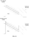
- Electrical adjustments in an electrical adjustment group corresponding to an antenna module may adjust downtilt angles of vertical lobes of beams generated by two antenna arrays in the antenna module, where the downtilt angle of the vertical lobe of the beam is an included angle between a direction of the beam and a horizontal line; and therefore may adjust directions of the beams generated by the two antenna arrays, so that the beams generated by the two antenna arrays jointly form a vertical-dimension wide beam or a vertical-dimension narrow beam.
- the beam jointly formed by the two beams generated by the two antenna arrays in the antenna module is referred to as a "combined beam" of the antenna module.
- the combined beam of the antenna module is a vertical-dimension narrow beam.
- the combined beam of the antenna module is a vertical-dimension wide beam. A larger difference between the downtilt angles of the vertical lobes of the beams generated by the two antenna arrays indicates a greater width of the combined beam in a vertical dimension.
- the first antenna array in the antenna module includes N1 longitudinally-arranged antenna array elements
- the second antenna array in the antenna module includes N2 longitudinally-arranged antenna array elements
- each antenna array element includes one positive-45-degree polarized array element and one negative-45-degree polarized array element
- N1 positive-45-degree polarized array elements of the first antenna array correspond to a third physical antenna port
- N1 negative-45-degree polarized array elements of the first antenna array correspond to a fourth physical antenna port
- N2 positive-45-degree polarized array elements of the second antenna array correspond to a first physical antenna port
- N2 negative-45-degree polarized array elements of the second antenna array correspond to a second physical antenna port
- both N1 and N2 are integers greater than 0.
- N1 N2.
- N1 and N2 are usually an even number greater than 0.
- Each antenna module in the antenna system is connected to an RRU in a base station, and a quantity of antenna modules in the antenna system is usually set to 1 or 2.
- the antenna system includes four physical antenna ports, where the quantity is greater than a quantity of physical antenna ports in the antenna system (namely, the antenna system provided in Manner 1 in the prior art) shown in FIG. 1 .
- the antenna system provided in this embodiment of the present invention can meet a requirement of a network system for a higher capacity.
- the antenna system includes eight physical antenna ports, where the quantity is greater than a quantity of physical antenna ports in each of the antenna system shown in FIG.
- the antenna system provided in this embodiment of the present invention can meet a requirement of a network system for a higher capacity.
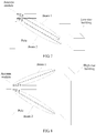
- the antenna module when the antenna system includes one antenna module, the antenna module is supported by a pole (for example, an electrical pole), a beam 1 indicates a beam generated by a first antenna array in the antenna module, ⁇ is a downtilt angle of a vertical lobe of the beam 1, a beam 2 indicates a beam generated by a second antenna array in the antenna module, and ⁇ is a downtilt angle of a vertical lobe of the beam 2.
- a combined beam of the antenna module when ⁇ and ⁇ are the same, a combined beam of the antenna module is a vertical-dimension narrow beam, and the narrow beam may be used to perform network coverage on a low-rise building and a street.
- a combined beam of the antenna module when ⁇ and ⁇ are different, a combined beam of the antenna module is a vertical-dimension wide beam, and the wide beam may be used to perform network coverage on a high-rise building.
- the antenna system provided in this embodiment of the present invention includes at least two antenna arrays. Therefore, at least two beams can be generated, and directions of the two beams can be controlled by using an electrical adjustment, so that the two beams jointly form a vertical-dimension wide beam (or narrow beam), to implement network coverage on a high-rise building (or a low-rise building).
- An embodiment of the present invention further provides a virtual antenna port mapping method. As shown in FIG. 9 , the method includes the following steps.
- a BBU obtains architecture information of an antenna system.
- the antenna system includes at least one antenna module, the antenna module includes a longitudinally-arranged first antenna array and a longitudinally-arranged second antenna array, and a downtilt angle of a vertical lobe of a beam generated by the first antenna array is the same as or different from a downtilt angle of a vertical lobe of a beam generated by the second antenna array.
- the method provided in this embodiment may be specifically performed by a baseband system in the BBU.
- the architecture information of the antenna system may include any piece of information related to the antenna system, for example, a quantity of antenna modules included in the antenna system, a quantity and an arrangement manner of antenna arrays included in the antenna module, a quantity and an arrangement manner of antenna array elements included in the antenna array, a quantity of physical antenna ports, and a correspondence between a physical antenna port and a polarized array element.
- the architecture information of the antenna system may be directly reported by the AAU to the BBU.
- the architecture information of the antenna system may be reported by the antenna system to the RRU, and then be reported by the RRU to the BBU.
- the antenna system may include at least one electrical adjustment group in a one-to-one correspondence with the at least one antenna module.
- the electrical adjustment group includes a first electrical adjustment and a second electrical adjustment.
- the first electrical adjustment in the electrical adjustment group corresponding to each antenna module is connected to the first antenna array in the antenna module, and is configured to adjust a downtilt angle of a vertical lobe of a beam generated by the first antenna array in the antenna module.
- the second electrical adjustment in the electrical adjustment group corresponding to each antenna module is connected to the second antenna array in the antenna module, and is configured to adjust a downtilt angle of a vertical lobe of a beam generated by the second antenna array in the antenna module. Therefore, the electrical adjustments may be used to enable the downtilt angle of the vertical lobe of the beam generated by the first antenna array to be the same as or different from the downtilt angle of the vertical lobe of the beam generated by the second antenna array.
- the BBU maps a virtual antenna port of the BBU to a physical antenna port in the antenna system based on the architecture information of the antenna system and the virtual antenna port.
- the BBU may map the virtual antenna port to the physical antenna port by using a virtual antenna mapping (Virtual Antenna Mapping, VAM for short) algorithm.
- VAM Virtual Antenna Mapping
- a downtilt angle of a vertical lobe of a beam generated by an antenna array may be adjusted by adjusting an electrical adjustment corresponding to the antenna array.
- the virtual antenna port may be mapped to the physical antenna port, so that the antenna module can generate the combined beam. Because the downtilt angles of the vertical lobes of the two beams that are generated by the two antenna arrays and that form the combined beam may be different, the combined beam may be a vertical-dimension wide beam, to implement network coverage on a high-rise building.
- the first antenna array in the antenna module includes N1 longitudinally-arranged antenna array elements
- the second antenna array in the antenna module includes N2 longitudinally-arranged antenna array elements
- each antenna array element includes one positive-45-degree polarized array element and one negative-45-degree polarized array element
- N1 positive-45-degree polarized array elements of the first antenna array correspond to a third physical antenna port
- N1 negative-45-degree polarized array elements of the first antenna array correspond to a fourth physical antenna port
- N2 positive-45-degree polarized array elements of the second antenna array correspond to a first physical antenna port
- N2 negative-45-degree polarized array elements of the second antenna array correspond to a second physical antenna port
- both N1 and N2 are integers greater than 0.
- step 902 are different when quantities of antenna modules included in the antenna system are different, when the downtilt angles of the vertical lobes of the beams generated by the first antenna array and the second antenna array in the antenna module are different, and when quantities of virtual antenna ports are different. Different cases are separately illustrated below.
- the antenna system includes one antenna module, downtilt angles of vertical lobes of beams generated by a first antenna array and a second antenna array in the antenna module are the same, and there are two virtual antenna ports.
- step 902 may be as follows: The BBU maps a virtual antenna port 0 in the two virtual antenna ports to a first physical antenna port and a third physical antenna port in the antenna module by using a weighted value [1, 1], and maps a virtual antenna port 1 in the two virtual antenna ports to a second physical antenna port and a fourth physical antenna port in the antenna module by using a weighted value [1, 1].
- the first physical antenna port is denoted as T/R0
- the second physical antenna port is denoted as T/R1
- the third physical antenna port is denoted as T/R2
- the fourth physical antenna port is denoted as T/R3
- the virtual antenna port 0 is a port 0
- the virtual antenna port 1 is a port 1
- a virtual antenna port 2 mentioned below is a port 2
- a virtual antenna port 3 is a port 3.
- FIG. 10 is a schematic diagram of mapping a virtual antenna port to a physical antenna port in Case 1.
- the BBU maps a port 0 to T/R0 and T/R2 by using a weighted value [1, 1], and maps a port 1 to T/R1 and T/R3 by using a weighted value [1, 1].
- a combined beam of the antenna module is a vertical-dimension narrow beam similar to that shown in FIG. 7 , and the narrow beam may perform network coverage on a low-rise building and a street.
- the antenna system includes one antenna module, downtilt angles of vertical lobes of beams generated by a first antenna array and a second antenna array in the antenna module are different, and there are two virtual antenna ports.
- step 902 may be as follows: The BBU maps a virtual antenna port 0 in the two virtual antenna ports to a first physical antenna port and a fourth physical antenna port in the antenna module by using a weighted value [1, 1], and maps a virtual antenna port 1 in the two virtual antenna ports to a second physical antenna port and a third physical antenna port in the antenna module by using a weighted value [1, -1].
- FIG. 11 is a schematic diagram of mapping a virtual antenna port to a physical antenna port in Case 2.
- the BBU maps a port 0 to T/R0 and T/R3 by using a weighted value [1, 1], and maps a port 1 to T/R1 and T/R2 by using a weighted value [1, -1].
- a combined beam of the antenna module is a vertical-dimension wide beam similar to that shown in FIG. 8 , and the wide beam may perform network coverage on a high-rise building.
- Case 3 The antenna system includes one antenna module, and there are four virtual antenna ports.
- step 902 may be as follows: The BBU maps a virtual antenna port 0 in the four virtual antenna ports to a first physical antenna port in the antenna module, maps a virtual antenna port 1 in the four virtual antenna ports to a second physical antenna port in the antenna module, maps a virtual antenna port 2 in the four virtual antenna ports to a third physical antenna port in the antenna module, and maps a virtual antenna port 3 in the four virtual antenna ports to a fourth physical antenna port in the antenna module.
- FIG. 12 is a schematic diagram of mapping a virtual antenna port to a physical antenna port in Case 3.
- the BBU maps a port 0 to T/R0, maps a port 2 to T/R1, maps a port 1 to T/R2, and maps a port 3 to T/R3.
- a combined beam of the antenna module is a vertical-dimension narrow beam similar to that shown in FIG. 7 , and the narrow beam may perform network coverage on a low-rise building and a street.
- a combined beam of the antenna module is a vertical-dimension wide beam similar to that shown in FIG. 8 , and the wide beam may perform network coverage on a high-rise building.
- the antenna system includes two antenna modules, downtilt angles of vertical lobes of beams generated by a first antenna array and a second antenna array in each antenna module are the same, and there are two virtual antenna ports.
- step 902 may be as follows:
- the BBU maps a virtual antenna port 0 in the two virtual antenna ports to a first physical antenna port of a first antenna module in the two antenna modules, a third physical antenna port of the first antenna module, a first physical antenna port of a second antenna module in the two antenna modules, and a third physical antenna port of the second antenna module by using a weighted value [1, 1, 1, 1], and maps a virtual antenna port 1 in the two virtual antenna ports to a second physical antenna port of the first antenna module in the two antenna modules, a fourth physical antenna port of the first antenna module, a second physical antenna port of the second antenna module in the two antenna modules, and a fourth physical antenna port of the second antenna module by using a weighted value [1, 1, 1, 1].
- FIG. 13 is a schematic diagram of mapping a virtual antenna port to a physical antenna port in Case 4.
- the BBU maps a port 0 to T/R0 and T/R2 of a first antenna module and T/R0 and T/R2 of a second antenna module by using a weighted value [1, 1, 1, 1], and maps a port 1 to T/R1 and T/R3 of the first antenna module and T/R1 and T/R3 of the second antenna module by using a weighted value [1, 1, 1, 1].
- a combined beam of the first antenna module and a combined beam of the second antenna module are both vertical-dimension narrow beams, and the two narrow beams may perform network coverage on different low-rise buildings or streets.
- the antenna system includes two antenna modules, downtilt angles of vertical lobes of beams generated by a first antenna array and a second antenna array in each antenna module are different, and there are two virtual antenna ports.
- step 902 may be as follows:
- the BBU maps a virtual antenna port 0 in the two virtual antenna ports to a first physical antenna port of a first antenna module in the two antenna modules, a fourth physical antenna port of the first antenna module, a first physical antenna port of a second antenna module in the two antenna modules, and a fourth physical antenna port of the second antenna module by using a weighted value [1, 1, 1, 1], and maps a virtual antenna port 1 in the two virtual antenna ports to a second physical antenna port of the first antenna module in the two antenna modules, a third physical antenna port of the first antenna module, a second physical antenna port of the second antenna module in the two antenna modules, and a third physical antenna port of the second antenna module by using a weighted value [-1, 1, -1, 1].
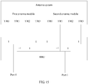
- FIG. 15 is a schematic diagram of mapping a virtual antenna port to a physical antenna port in Case 5.
- the BBU maps a port 0 to T/R0 and T/R3 of a first antenna module and T/R0 and T/R3 of a second antenna module by using a weighted value [1, 1, 1, 1], and maps a port 1 to T/R1 and T/R2 of the first antenna module and T/R1 and T/R2 of the second antenna module by using a weighted value [-1, 1, -1, 1].
- a combined beam of the first antenna module and a combined beam of the second antenna module are both vertical-dimension wide beams, and the two wide beams may perform network coverage on different high-rise buildings.
- the antenna system includes two antenna modules, downtilt angles of vertical lobes of beams generated by a first antenna array and a second antenna array in a first antenna module in the two antenna modules are different, downtilt angles of vertical lobes of beams generated by a first antenna array and a second antenna array in a second antenna module in the two antenna modules are the same, and there are two virtual antenna ports.
- step 902 may be as follows:
- the BBU maps a virtual antenna port 0 in the two virtual antenna ports to a first physical antenna port of a first antenna module in the two antenna modules, a fourth physical antenna port of the first antenna module, a first physical antenna port of a second antenna module in the two antenna modules, and a third physical antenna port of the second antenna module by using a weighted value [1, 1, 1, 1], and maps a virtual antenna port 1 in the two virtual antenna ports to a second physical antenna port of the first antenna module in the two antenna modules, a third physical antenna port of the first antenna module, a second physical antenna port of the second antenna module in the two antenna modules, and a fourth physical antenna port of the second antenna module by using a weighted value [-1, 1, 1, 1].
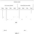
- FIG. 17 is a schematic diagram of mapping a virtual antenna port to a physical antenna port in Case 6.
- the BBU maps a port 0 to T/R0 and T/R3 of a first antenna module and T/R0 and T/R2 of a second antenna module by using a weighted value [1, 1, 1, 1], and maps a port 1 to T/R1 and T/R2 of the first antenna module and T/R1 and T/R3 of the second antenna module by using a weighted value [-1, 1, 1, 1].
- a combined beam of the first antenna module is a vertical-dimension wide beam, and the wide beam may perform network coverage on a high-rise building; and a combined beam of the second antenna module is a vertical-dimension narrow beam, and the narrow beam may perform network coverage on a low-rise building and a street.
- Case 7 The antenna system includes two antenna modules, and there are four virtual antenna ports.
- step 902 may be as follows:
- the BBU maps a virtual antenna port 0 in the four virtual antenna ports to a first physical antenna port of a first antenna module in the two antenna modules and a first physical antenna port of a second antenna module in the two antenna modules by using a weighted value [1, 1], maps a virtual antenna port 1 in the four virtual antenna ports to a second physical antenna port of the first antenna module in the two antenna modules and a second physical antenna port of the second antenna module in the two antenna modules by using a weighted value [1, 1], maps a virtual antenna port 2 in the four virtual antenna ports to a third physical antenna port of the first antenna module in the two antenna modules and a third physical antenna port of the second antenna module in the two antenna modules by using a weighted value [1, 1], and maps a virtual antenna port 3 in the four virtual antenna ports to a fourth physical antenna port of the first antenna module in the two antenna modules and a fourth physical antenna port of the second antenna module in the two antenna modules by using a weighted value [1, 1
- FIG. 19 is a schematic diagram of mapping a virtual antenna port to a physical antenna port in case 7.
- the BBU maps a port 0 to T/R0 of a first antenna module and T/R0 of a second antenna module by using a weighted value [1, 1], maps a port 1 to T/R2 of the first antenna module and T/R2 of the second antenna module by using a weighted value [1, 1], maps a port 2 to T/R1 of the first antenna module and T/R1 of the second antenna module by using a weighted value [1, 1], and maps a port 3 to T/R3 of the first antenna module and T/R3 of the second antenna module by using a weighted value [1, 1].
- a combined beam generated by the antenna module is a vertical-dimension narrow beam, which may perform network coverage on a low-rise building or a street.
- a combined beam generated by the antenna module is a vertical-dimension wide beam, which may perform network coverage on a high-rise building. For details, refer to FIG. 18 .
- the method further includes: compensating, by the BBU, for a phase difference between the beam generated by the first antenna array in the antenna module and the beam generated by the second antenna array.
- a specific compensation method may be: setting a phase of the beam generated by the first antenna array in the antenna module and a phase of the beam generated by the second antenna array, where the phase of the beam generated by the first antenna array in the antenna module is 360 ⁇ sin((ET-1) ⁇ 15/14.4/180 ⁇ ⁇ ) ⁇ 330 ⁇ Frq/300 greater than the phase of the beam generated by the second antenna array in the antenna module, ET is the downtilt angle of the vertical lobe of the beam generated by each of the first antenna array and the second antenna array in the antenna module, Frq is a frequency of a transmitted signal of a physical antenna port, and " ⁇ " indicates "multiply”.
- the beam 1 generated by the first antenna array and the beam 2 generated by the second antenna array jointly form a vertical-dimension narrow beam.
- the beam 1 generated by the first antenna array and the beam 2 generated by the second antenna array jointly form a vertical-dimension narrow beam.
- the BBU needs to compensate for the phase difference between the beam 1 and the beam 2.
- the compensation may be implemented by enabling a phase of the beam generated by the first antenna array to be 360 ⁇ sin((ET-1) ⁇ 15/14.4/180 ⁇ ⁇ ) ⁇ 330 ⁇ Frq/300 greater than a phase of the beam generated by the second antenna array.
- the phase of the beam generated by the first antenna array may be set to 0, and the phase of the beam generated by the second antenna array may be set to -219.3576 degrees.
- two beams generated by one antenna module may cover one cell with four channels, or may cover two inter-frequency cells with two channels.
- a network throughput can be effectively increased by implementing network coverage in different scenarios by using the vertical-dimension narrow beam and the vertical-dimension wide beam generated by the antenna system in this embodiment of the present invention.
- Table 1 shows increments, obtained through simulation, in network throughputs in different scenarios in which an AAU is EM 1.0 (Easy Macro 1.0) and EM 2.0 (Easy Macro 2.0).
- EM 1.0 implements network coverage in Manner 1 in the prior art
- the AAU, in the present invention obtained by integrating the RRU with the antenna system is denoted as EM 2.0.
- EM 2.0-SU indicates a single-user scenario
- EM 2.0-MU indicates a multi-user scenario
- DL indicates a downlink
- UL indicates an uplink.
- Scenario 1 is a scenario of covering a street and a one- and two-rise building along the street
- Scenario 2 is a scenario of covering a four- to eight-rise building within a range of 200 meters along a street
- Scenario 3 is a scenario of covering a mid- or high-rise building (with a building height of 60 meters).
- the BBU includes a corresponding hardware structure and/or a software unit for performing the steps in the method.
- a person skilled in the art should be easily aware that, units and algorithm steps in the examples described with reference to the embodiments disclosed in this specification can be implemented by hardware or a combination of hardware and computer software in the present invention. Whether a function is specifically performed by hardware or hardware driven by computer software depends on particular applications and design constraints of the technical solutions. A person skilled in the art may use different methods to implement the described functions for each particular application, but it should not be considered that the implementation goes beyond the scope of the present invention.
- the BBU may be divided into functional units according to the foregoing method embodiment.
- each functional unit may be obtained through division based on each corresponding method step, or two or more functional units may be integrated into one processing unit.
- the integrated unit may be implemented in a form of hardware, or may be implemented in a form of a software functional unit.
- unit division in the embodiments of the present invention is an example, and is merely logical function division. There may be another division manner during actual implementation.
- FIG. 20 is a schematic composition diagram of a BBU 20.
- the BBU 20 includes:
- the first antenna array in the antenna module includes N1 longitudinally-arranged antenna array elements
- the second antenna array in the antenna module includes N2 longitudinally-arranged antenna array elements
- each antenna array element includes one positive-45-degree polarized array element and one negative-45-degree polarized array element
- N1 positive-45-degree polarized array elements of the first antenna array correspond to a third physical antenna port
- N1 negative-45-degree polarized array elements of the first antenna array correspond to a fourth physical antenna port
- N2 positive-45-degree polarized array elements of the second antenna array correspond to a first physical antenna port
- N2 negative-45-degree polarized array elements of the second antenna array correspond to a second physical antenna port
- both N1 and N2 are integers greater than 0.
- the antenna system includes one antenna module, a downtilt angle of a vertical lobe of a beam generated by a first antenna array in the antenna module is the same as a downtilt angle of a vertical lobe of a beam generated by a second antenna array in the antenna module, there are two virtual antenna ports, and the processing unit 2002 is specifically configured to: map, by the BBU, a virtual antenna port 0 in the two virtual antenna ports to a first physical antenna port and a third physical antenna port in the antenna module by using a weighted value [1, 1], and map a virtual antenna port 1 in the two virtual antenna ports to a second physical antenna port and a fourth physical antenna port in the antenna module by using a weighted value [1, 1].
- the antenna system includes one antenna module, a downtilt angle of a vertical lobe of a beam generated by a first antenna array in the antenna module is different from a downtilt angle of a vertical lobe of a beam generated by a second antenna array in the antenna module, there are two virtual antenna ports, and the processing unit 2002 is specifically configured to: map, by the BBU, a virtual antenna port 0 in the two virtual antenna ports to a first physical antenna port and a fourth physical antenna port in the antenna module by using a weighted value [1, 1], and map a virtual antenna port 1 in the two virtual antenna ports to a second physical antenna port and a third physical antenna port in the antenna module by using a weighted value [1, -1].
- the antenna system includes one antenna module, there are four virtual antenna ports
- the processing unit 2002 is specifically configured to: map, by the BBU, a virtual antenna port 0 in the four virtual antenna ports to a first physical antenna port in the antenna module, map a virtual antenna port 1 in the four virtual antenna ports to a second physical antenna port in the antenna module, map a virtual antenna port 2 in the four virtual antenna ports to a third physical antenna port in the antenna module, and map a virtual antenna port 3 in the four virtual antenna ports to a fourth physical antenna port in the antenna module.
- the antenna system includes two antenna modules, a downtilt angle of a vertical lobe of a beam generated by a first antenna array in each antenna module is the same as a downtilt angle of a vertical lobe of a beam generated by a second antenna array in the antenna module, there are two virtual antenna ports, and the processing unit 2002 is specifically configured to: map, by the BBU, a virtual antenna port 0 in the two virtual antenna ports to a first physical antenna port of a first antenna module in the two antenna modules, a third physical antenna port of the first antenna module, a first physical antenna port of a second antenna module in the two antenna modules, and a third physical antenna port of the second antenna module by using a weighted value [1, 1, 1, 1], and map a virtual antenna port 1 in the two virtual antenna ports to a second physical antenna port of the first antenna module in the two antenna modules, a fourth physical antenna port of the first antenna module, a second physical antenna port of the second antenna module in the two antenna modules, and a fourth physical antenna port of the first
- the antenna system includes two antenna modules, a downtilt angle of a vertical lobe of a beam generated by a first antenna array in each antenna module is different from a downtilt angle of a vertical lobe of a beam generated by a second antenna array in the antenna module, there are two virtual antenna ports, and the processing unit 2002 is specifically configured to: map, by the BBU, a virtual antenna port 0 in the two virtual antenna ports to a first physical antenna port of a first antenna module in the two antenna modules, a fourth physical antenna port of the first antenna module, a first physical antenna port of a second antenna module in the two antenna modules, and a fourth physical antenna port of the second antenna module by using a weighted value [1, 1, 1, 1], and map a virtual antenna port 1 in the two virtual antenna ports to a second physical antenna port of the first antenna module in the two antenna modules, a third physical antenna port of the first antenna module, a second physical antenna port of the second antenna module in the two antenna modules, and a third physical antenna port of the first antenna
- the antenna system includes two antenna modules, a downtilt angle of a vertical lobe of a beam generated by a first antenna array in a first antenna module in the two antenna modules is different from a downtilt angle of a vertical lobe of a beam generated by a second antenna array in the first antenna module, a downtilt angle of a vertical lobe of a beam generated by a first antenna array in a second antenna module in the two antenna modules is the same as a downtilt angle of a vertical lobe of a beam generated by a second antenna array in the second antenna module, there are two virtual antenna ports, and the processing unit 2002 is specifically configured to: map, by the BBU, a virtual antenna port 0 in the two virtual antenna ports to a first physical antenna port of the first antenna module in the two antenna modules, a fourth physical antenna port of the first antenna module, a first physical antenna port of the second antenna module in the two antenna modules, and a third physical antenna port of the second antenna module by using a weighted
- the antenna system includes two antenna modules, there are four virtual antenna ports
- the processing unit 2002 is specifically configured to: map, by the BBU, a virtual antenna port 0 in the four virtual antenna ports to a first physical antenna port of a first antenna module in the two antenna modules and a first physical antenna port of a second antenna module in the two antenna modules by using a weighted value [1, 1], map a virtual antenna port 1 in the four virtual antenna ports to a second physical antenna port of the first antenna module in the two antenna modules and a second physical antenna port of the second antenna module in the two antenna modules by using a weighted value [1, 1], map a virtual antenna port 2 in the four virtual antenna ports to a third physical antenna port of the first antenna module in the two antenna modules and a third physical antenna port of the second antenna module in the two antenna modules by using a weighted value [1, 1], and map a virtual antenna port 3 in the four virtual antenna ports to a fourth physical antenna port of the first antenna module in the two antenna modules and a fourth physical antenna port of the second
- the processing unit 2002 is further configured to: compensate for a phase difference between the beam generated by the first antenna array in the antenna module and the beam generated by the second antenna array.
- the processing unit 2002 is specifically configured to: set a phase of the beam generated by the first antenna array in the antenna module and a phase of the beam generated by the second antenna array, where the phase of the beam generated by the first antenna array in the antenna module is 360 ⁇ sin((ET-1) ⁇ 15/14.4/180 ⁇ ⁇ ) ⁇ 330 ⁇ Frq/300 greater than the phase of the beam generated by the second antenna array in the antenna module, ET is the downtilt angle of the vertical lobe of the beam generated by each of the first antenna array and the second antenna array in the antenna module, and Frq is a frequency of a transmitted signal of a physical antenna port.
- Each unit in the BBU 20 is configured to perform the foregoing method. Therefore, for a beneficial effect of the BBU 20, refer to the beneficial effect of the foregoing method. Details are not described herein again.
- Each "unit” described above may be an application-specific integrated circuit (application-specific integrated circuit, ASIC for short) circuit, a processor that executes one or more software or firmware programs, a memory, an integrated logic circuit, and/or another device that can provide the foregoing functions.
- the obtaining unit 2001 may be implemented by using a communications interface or a receiver, and the processing unit 2002 may be implemented by a processor.
- the foregoing method may be implemented by using a BBU 21 shown in FIG. 21 .
- the BBU 21 includes a processor 2101, a memory 2102, a bus 2103, and a communications interface 2104.
- the processor 2101 may be a general-purpose central processing unit (central processing unit, CPU for short), a microprocessor, an ASIC, or one or more integrated circuits for controlling program execution in the solutions of the present invention.
- CPU central processing unit
- ASIC application specific integrated circuit
- the memory 2102 may be a read-only memory (read-only memory, ROM for short) or another type of static storage device that can store static information and an instruction, or a random access memory (random access memory, RAM for short) or another type of dynamic storage device that can store information and an instruction, or may be an electrically erasable programmable read-only memory (electrically erasable programmable read-only memory, EEPROM for short), a compact disc read-only memory (compact disc read-only memory, CD-ROM for short) or other compact disc storage, optical disc storage (including a compact disc, a laser disc, an optical disc, a digital versatile disc, a Blu-ray disc, or the like), a disk storage medium or another magnetic storage device, or any other medium that can be configured to carry or store expected program code having an instruction or data structure form and that can be accessed by a computer.
- ROM read-only memory
- RAM random access memory
- EEPROM electrically erasable programmable read-only memory
- CD-ROM
- the communications interface 2104 may be an apparatus such as a transceiver, and is configured to communicate with another device.
- the processor 2101, the memory 2102, and the communications interface 2104 are connected through the bus 2103.
- the bus 2103 may include a channel, and transmit information between the processor 2101, the memory 2102, and the communications interface 2104.
- the memory 2102 may exist independently and is connected to the processor 2101 through the bus 2103.
- the memory 2102 may alternatively be integrated with the processor 2101.
- the bus 2103 may be a peripheral component interconnect (peripheral component interconnect, PCI for short) bus, an extended industry standard architecture (extended industry standard architecture, EISA for short) bus, or the like.
- the bus may be classified into an address bus, a data bus, a control bus, and the like. For ease of representation, only one thick line is used to represent the bus in FIG. 21 , but it does not mean that there is only one bus or only one type of bus.
- the memory 2102 is configured to store a computer execution instruction, and the processor 2101 executes the computer execution instruction stored in the memory 2102, to perform the following actions:
- the processor 2101 may further perform other steps in the foregoing method by executing the computer execution instruction stored in the memory 2102. For details, refer to the foregoing method. Details are not described herein again.
- Each device in the BBU 21 is configured to perform the foregoing method. Therefore, for a beneficial effect of the BBU 21, refer to the beneficial effect of the foregoing method. Details are not described herein again.
- An embodiment of the present invention further provides a computer storage medium, configured to store a computer software instruction used by the BBU.
- the computer software instruction includes a program designed for performing the method embodiment.
- a virtual antenna port mapping method may be implemented by executing the stored program.
- the embodiments of the present invention may be provided as a method, an apparatus (device), or a computer program product. Therefore, the present invention may use a form of hardware only embodiments, software only embodiments, or embodiments with a combination of software and hardware. Moreover, the present invention may use a form of a computer program product implemented on one or more computer-usable storage media (including but not limited to a disk memory, a CD-ROM, an optical memory, and the like) that include computer-usable program code.
- the computer program is stored/distributed in a proper medium and is provided as or used as a part of the hardware together with another hardware, or may be distributed in another form, for example, through the Internet or another wired or wireless telecommunications system.
- These computer program instructions may be provided for a general-purpose computer, a dedicated computer, an embedded processor, or a processor of another programmable data processing device to generate a machine, so that the instructions executed by the computer or the processor of the another programmable data processing device generate an apparatus for implementing a specified function in one or more processes in the flowcharts and/or in one or more blocks in the block diagrams.
- These computer program instructions may also be stored in a computer readable memory that can instruct a computer or another programmable data processing device to work in a specific manner, so that the instructions stored in the computer readable memory generate an artifact that includes an instruction apparatus.
- the instruction apparatus implements a specified function in one or more processes in the flowcharts and/or in one or more blocks in the block diagrams.
- These computer program instructions may also be loaded onto a computer or another programmable data processing device, so that a series of operations and steps are performed on the computer or the another programmable device, thereby generating computer-implemented processing. Therefore, the instructions executed on the computer or the another programmable device provide steps for implementing a specified function in one or more processes in the flowcharts and/or in one or more blocks in the block diagrams.
Landscapes
- Engineering & Computer Science (AREA)
- Computer Networks & Wireless Communication (AREA)
- Signal Processing (AREA)
- Variable-Direction Aerials And Aerial Arrays (AREA)
Applications Claiming Priority (1)
| Application Number | Priority Date | Filing Date | Title |
|---|---|---|---|
| PCT/CN2016/106456 WO2018090342A1 (fr) | 2016-11-18 | 2016-11-18 | Système d'antenne, et procédé et appareil de mappage d'accès d'antenne virtuelle |
Publications (2)
| Publication Number | Publication Date |
|---|---|
| EP3528342A1 true EP3528342A1 (fr) | 2019-08-21 |
| EP3528342A4 EP3528342A4 (fr) | 2019-11-13 |
Family
ID=62145150
Family Applications (1)
| Application Number | Title | Priority Date | Filing Date |
|---|---|---|---|
| EP16921862.5A Withdrawn EP3528342A4 (fr) | 2016-11-18 | 2016-11-18 | Système d'antenne, et procédé et appareil de mappage d'accès d'antenne virtuelle |
Country Status (6)
| Country | Link |
|---|---|
| US (1) | US20190273542A1 (fr) |
| EP (1) | EP3528342A4 (fr) |
| JP (1) | JP2019536368A (fr) |
| KR (1) | KR20190066074A (fr) |
| CN (1) | CN109964369A (fr) |
| WO (1) | WO2018090342A1 (fr) |
Cited By (1)
| Publication number | Priority date | Publication date | Assignee | Title |
|---|---|---|---|---|
| EP3624359A4 (fr) * | 2017-05-31 | 2020-04-08 | Huawei Technologies Co., Ltd. | Procédé de mise en correspondance de port d'antenne et dispositif de réseau |
Families Citing this family (6)
| Publication number | Priority date | Publication date | Assignee | Title |
|---|---|---|---|---|
| KR102562821B1 (ko) * | 2018-10-19 | 2023-08-02 | 삼성전자주식회사 | 무선 신호를 수신 및 측정하기 위한 장치 및 방법 |
| CN114552214B (zh) | 2020-11-24 | 2024-12-27 | 华为技术有限公司 | 天线系统 |
| CN114466470B (zh) | 2021-12-27 | 2025-02-25 | 华为技术有限公司 | 信号处理设备及数据传输方法 |
| US12464378B2 (en) * | 2022-11-16 | 2025-11-04 | T-Mobile Innovations Llc | Center of gravity for network access and communication service |
| CN118117280A (zh) * | 2022-11-30 | 2024-05-31 | 上海华为技术有限公司 | 谐振器、滤波器、动态天线单元及射频拉远单元 |
| CN121011819A (zh) * | 2024-05-24 | 2025-11-25 | 华为技术有限公司 | 一种天线装置以及基站 |
Family Cites Families (14)
| Publication number | Priority date | Publication date | Assignee | Title |
|---|---|---|---|---|
| WO2008060206A1 (fr) * | 2006-11-14 | 2008-05-22 | Telefonaktiebolaget Lm Ericsson (Publ) | Antenne à diagramme de rayonnement amélioré |
| CN101355722B (zh) * | 2007-07-25 | 2012-02-08 | 中兴通讯股份有限公司 | 混合多模通信系统 |
| WO2012016941A1 (fr) * | 2010-08-04 | 2012-02-09 | Nokia Siemens Networks Oy | Antenne large bande et système de station de base radio pour traiter au moins deux bandes de fréquences ou deux normes radio dans un système de radiocommunications |
| CN102347529A (zh) * | 2010-08-04 | 2012-02-08 | 诺基亚西门子通信公司 | 用于处理无线电通信系统中的至少两个频带或无线电标准的宽带天线和无线电基站系统 |
| CN102157791A (zh) * | 2010-12-29 | 2011-08-17 | 华为技术有限公司 | 宽频天线系统、基站和宽频天线下倾角的调整方法 |
| CN103138816A (zh) * | 2011-12-05 | 2013-06-05 | 上海贝尔股份有限公司 | 一种子阵列互补波束赋形的方法与设备 |
| WO2014178124A1 (fr) * | 2013-04-30 | 2014-11-06 | ソフトバンクBb株式会社 | Dispositif d'antenne à polarisation transversale et procédé de test pour une station de base sans fil portable |
| CN103858359B (zh) * | 2013-12-27 | 2017-05-10 | 华为技术有限公司 | 一种天线阵列、信号映射的方法及基站 |
| CN103840261B (zh) * | 2014-03-07 | 2017-04-19 | 华为技术有限公司 | 天线装置和调整天线波束的方法 |
| WO2016000096A1 (fr) * | 2014-06-09 | 2016-01-07 | 华为技术有限公司 | Procédé et dispositif de mappage de ports d'antenne |
| US9806778B2 (en) * | 2014-11-11 | 2017-10-31 | Electronics And Telecommunications Research Institute | Method and apparatus for mapping virtual antenna to physical antenna |
| CN105991172A (zh) * | 2015-02-16 | 2016-10-05 | 富士通株式会社 | 天线阵列的虚拟化模型选择方法、装置以及通信系统 |
| GB2538070A (en) * | 2015-05-04 | 2016-11-09 | Kathrein Werke Kg | Antenna system |
| CN105259544B (zh) * | 2015-10-31 | 2017-09-15 | 零八一电子集团有限公司 | 有源相控阵雷达t/r组件幅相测试系统 |
-
2016
- 2016-11-18 WO PCT/CN2016/106456 patent/WO2018090342A1/fr not_active Ceased
- 2016-11-18 JP JP2019526509A patent/JP2019536368A/ja not_active Withdrawn
- 2016-11-18 EP EP16921862.5A patent/EP3528342A4/fr not_active Withdrawn
- 2016-11-18 CN CN201680090955.8A patent/CN109964369A/zh active Pending
- 2016-11-18 KR KR1020197014979A patent/KR20190066074A/ko not_active Withdrawn
-
2019
- 2019-05-16 US US16/414,718 patent/US20190273542A1/en not_active Abandoned
Cited By (2)
| Publication number | Priority date | Publication date | Assignee | Title |
|---|---|---|---|---|
| EP3624359A4 (fr) * | 2017-05-31 | 2020-04-08 | Huawei Technologies Co., Ltd. | Procédé de mise en correspondance de port d'antenne et dispositif de réseau |
| US11109261B2 (en) | 2017-05-31 | 2021-08-31 | Huawei Technologies Co., Ltd. | Antenna port mapping method and network device |
Also Published As
| Publication number | Publication date |
|---|---|
| WO2018090342A1 (fr) | 2018-05-24 |
| US20190273542A1 (en) | 2019-09-05 |
| JP2019536368A (ja) | 2019-12-12 |
| EP3528342A4 (fr) | 2019-11-13 |
| KR20190066074A (ko) | 2019-06-12 |
| CN109964369A (zh) | 2019-07-02 |
Similar Documents
| Publication | Publication Date | Title |
|---|---|---|
| EP3528342A1 (fr) | Système d'antenne, et procédé et appareil de mappage d'accès d'antenne virtuelle | |
| US11432165B2 (en) | Method and apparatus for adjusting broadcast beam domain | |
| EP3629510B1 (fr) | Procédé de transmission de données, dispositif, équipement côté réseau, et équipement d'utilisateur | |
| EP3068156B1 (fr) | Procédé de transmission de mode de précodage de faisceaux, et procédé et dispositif d'ordonnancement | |
| CN108781416B (zh) | 用于上行链路发送功率控制方法、装置和计算机可读存储介质 | |
| EP3557808A1 (fr) | Procédé de commande de puissance pour signal de référence de mesure de liaison montante, dispositif réseau et dispositif terminal | |
| JP4713549B2 (ja) | 電力制御のためのシステムおよび方法、および遠隔無線ユニット | |
| CN109963291B (zh) | 一种覆盖范围自适应调整的方法和基站 | |
| CN103167512B (zh) | 基站天线下倾角确定方法、装置和基站设备 | |
| EP3065437B1 (fr) | Procédé de traitement de signal et station de base | |
| EP3547741A1 (fr) | Procédé de commande de puissance et dispositif de communication | |
| CN103178882B (zh) | 一种3d mimo下倾角调整方法、装置及基站 | |
| CN104955061A (zh) | 波束选择方法及基站 | |
| WO2014056162A1 (fr) | Procédé de communication par système réseau d'antennes distribuées et système réseau | |
| EP3840452A1 (fr) | Procédé et appareil de réglage d'angle de mi-puisssance d'antenne | |
| JP2018506933A (ja) | アンテナ選択による室内dasシステムの小型基地局アップリンク信号干渉に対する方法 | |
| US20240297696A1 (en) | Signal processing method and related apparatus | |
| US10582391B2 (en) | Antenna system and antenna system adjustment method | |
| US10447363B2 (en) | Multi-antenna transmission method in co-cell network, and base station | |
| US20190349050A1 (en) | Beam Generation Method And Base Station | |
| CN106332180A (zh) | 一种负载均衡的方法及装置 | |
| CN104469787A (zh) | 一种信号覆盖的方法及装置 | |
| JP7127070B2 (ja) | アンテナポートマッピング方法およびネットワーク機器 | |
| US10804981B1 (en) | Dynamic determination of antenna array mode | |
| CN107087277A (zh) | 一种实现超远覆盖的双拼设备、系统及方法 |
Legal Events
| Date | Code | Title | Description |
|---|---|---|---|
| STAA | Information on the status of an ep patent application or granted ep patent |
Free format text: STATUS: THE INTERNATIONAL PUBLICATION HAS BEEN MADE |
|
| PUAI | Public reference made under article 153(3) epc to a published international application that has entered the european phase |
Free format text: ORIGINAL CODE: 0009012 |
|
| STAA | Information on the status of an ep patent application or granted ep patent |
Free format text: STATUS: REQUEST FOR EXAMINATION WAS MADE |
|
| 17P | Request for examination filed |
Effective date: 20190513 |
|
| AK | Designated contracting states |
Kind code of ref document: A1 Designated state(s): AL AT BE BG CH CY CZ DE DK EE ES FI FR GB GR HR HU IE IS IT LI LT LU LV MC MK MT NL NO PL PT RO RS SE SI SK SM TR |
|
| AX | Request for extension of the european patent |
Extension state: BA ME |
|
| RIC1 | Information provided on ipc code assigned before grant |
Ipc: H01Q 21/26 20060101ALI20191003BHEP Ipc: H01Q 25/00 20060101ALI20191003BHEP Ipc: H01Q 1/24 20060101ALI20191003BHEP Ipc: H04B 7/00 20060101ALI20191003BHEP Ipc: H01Q 21/28 20060101ALI20191003BHEP Ipc: H01Q 21/24 20060101ALI20191003BHEP Ipc: H01Q 25/02 20060101ALI20191003BHEP Ipc: H01Q 21/00 20060101AFI20191003BHEP Ipc: H01Q 3/26 20060101ALI20191003BHEP |
|
| A4 | Supplementary search report drawn up and despatched |
Effective date: 20191010 |
|
| STAA | Information on the status of an ep patent application or granted ep patent |
Free format text: STATUS: THE APPLICATION HAS BEEN WITHDRAWN |
|
| 18W | Application withdrawn |
Effective date: 20191216 |