EP3528443A1 - Verfahren zum berechnen eines schätzwerts eines modulierten digitalen signals und seiner zuverlässigkeit - Google Patents
Verfahren zum berechnen eines schätzwerts eines modulierten digitalen signals und seiner zuverlässigkeit Download PDFInfo
- Publication number
- EP3528443A1 EP3528443A1 EP19156763.5A EP19156763A EP3528443A1 EP 3528443 A1 EP3528443 A1 EP 3528443A1 EP 19156763 A EP19156763 A EP 19156763A EP 3528443 A1 EP3528443 A1 EP 3528443A1
- Authority
- EP
- European Patent Office
- Prior art keywords
- signal
- receiver
- soft
- parameters
- reliability
- Prior art date
- Legal status (The legal status is an assumption and is not a legal conclusion. Google has not performed a legal analysis and makes no representation as to the accuracy of the status listed.)
- Granted
Links
Images


Classifications
-
- H—ELECTRICITY
- H04—ELECTRIC COMMUNICATION TECHNIQUE
- H04L—TRANSMISSION OF DIGITAL INFORMATION, e.g. TELEGRAPHIC COMMUNICATION
- H04L25/00—Baseband systems
- H04L25/02—Details ; arrangements for supplying electrical power along data transmission lines
- H04L25/03—Shaping networks in transmitter or receiver, e.g. adaptive shaping networks
- H04L25/03006—Arrangements for removing intersymbol interference
- H04L25/03171—Arrangements involving maximum a posteriori probability [MAP] detection
-
- H—ELECTRICITY
- H04—ELECTRIC COMMUNICATION TECHNIQUE
- H04L—TRANSMISSION OF DIGITAL INFORMATION, e.g. TELEGRAPHIC COMMUNICATION
- H04L25/00—Baseband systems
- H04L25/02—Details ; arrangements for supplying electrical power along data transmission lines
- H04L25/03—Shaping networks in transmitter or receiver, e.g. adaptive shaping networks
- H04L25/03006—Arrangements for removing intersymbol interference
- H04L25/03178—Arrangements involving sequence estimation techniques
- H04L25/03312—Arrangements specific to the provision of output signals
- H04L25/03318—Provision of soft decisions
-
- H—ELECTRICITY
- H04—ELECTRIC COMMUNICATION TECHNIQUE
- H04L—TRANSMISSION OF DIGITAL INFORMATION, e.g. TELEGRAPHIC COMMUNICATION
- H04L25/00—Baseband systems
- H04L25/02—Details ; arrangements for supplying electrical power along data transmission lines
- H04L25/06—DC level restoring means; Bias distortion correction ; Decision circuits providing symbol by symbol detection
- H04L25/067—DC level restoring means; Bias distortion correction ; Decision circuits providing symbol by symbol detection providing soft decisions, i.e. decisions together with an estimate of reliability
Definitions
- the invention relates to a method for improving the calculation of the estimation of the symbols of a modulated digital signal and their reliability, for any task that requires such an estimate.
- the symbol estimation presented here can be used to derive an estimate of the channel (or some of its parameters) between the transmitter and the receiver. It can be used to derive an estimate of the signal or receiver parameters such as, for example, the clock offset, or the time of signal reception. It can also be used to derive link quality metrics, such as mutual information between the transmitted and received symbols, the reliability of the sent signal estimate, the signal-to-noise ratio or the signal-to-noise plus interference ratio. .
- the invention also relates to a method for suppressing interference within a signal received on a receiver. It applies in particular to equalization with an adaptive receiver equalizer type feedback decision or DFE (Digital Feedback Equalizer) for equalization of symbols received.
- DFE Digital Feedback Equalizer
- the field of the invention is that of digital radio communication systems and, inter alia, transmitters and receivers for multichannel communications, that is to say comprising several antennas.
- the invention also relates to multi-user systems in which the communication resources are shared between several users who can simultaneously communicate by sharing frequency bands or slots or time slots.
- the invention relates to all multi-user communication systems in which high levels of interference are generated both between transmitters associated with different users but also between the symbols conveyed by a signal transmitted by a user of the device. makes disturbances inherent to the propagation channel.
- the invention precisely relates to the field of interference suppression in a multi-user context in the context of iterative receivers, which consists in the iteration of the interference suppression and decoding functions in the objective final to improve the bit error rate or the packet error rate on the decoded symbols.
- the invention finds inter alia its application in cellular communication systems such as the 3GPP LTE system.
- the invention also aims at a method of equalization in the frequency domain and which is flexible, adapted to a single-user context, or multi-user and with a receiver implementing a treatment is non-iterative or iterative.
- a transfer of information from a source to a destination involves propagation through a channel which may be, for example, a radio channel, a wired channel (such as a coaxial cable), etc.
- Some propagation means generate inter-symbol interference on the received signal.
- the received signal sampled at a given moment after compensation of propagation delays and processing, and having a correct synchronization, not only contains the symbol sent (possibly amplified and with a phase disturbance) plus noise, but a mixture or linear combination of symbols sent.
- ISI intersymbol interference
- Many equalization methods are described in the prior art.
- the goal is to achieve optimal performance given by the adapted filter terminal (which is a lower bound on the packet error rate) while being easy to use.
- the algorithms must therefore have computing complexity, memory occupancy and processing latency compatible, both to the applications that use the receivers in question and to the constraints of the hardware platforms on which they are implemented.
- the technical problem is therefore to find algorithms that find a good compromise performance / complexity of implementation with respect to the targeted applications.
- equalizers There are several equalizer classes: linear equalizers, decision feedback equalizers (DFEs), interference canceling equalizers (Interference Cancellation), and maximum posteriori (MAP) detectors. ), or detectors that estimate a Maximum Likelihood Sequence Estimation (MLSE). These equalizers can be declined in iterative form. Particular iterative receivers are so-called “turbo" receivers, where there is a repetitive exchange of extrinsic probabilistic information between processing blocks, for example between the equalization block and the decoding block.
- Expectancy propagation EP can also be seen as a message passing algorithm known as the "message passing”, in particular as a generalization of the belief propagation algorithm (Belief Propagation - BP - in English). English) to cases of non-categorical probability distributions but belonging to the exponential family.
- this concept allows for better message passing with minimum average square error (MMSE) estimators.
- MMSE minimum average square error
- the reference [6] uses this new soft return in the context of a multiple-input multiple-output (MIMO) receiver, which makes it possible to better approach the MAP performance.
- MIMO multiple-input multiple-output
- reference [17] studies a return signal based on the concept of PE from the soft demodulator, for block linear equalizers in the time domain.
- the solution described in [17] requires the inversion of matrices that potentially have a large size and therefore with considerable computational and memory complexity.
- As part of the turbo-equalization reference [15] is an extension of the reference [17], with its defects in terms of complexity.
- Reference [16] deals with frequency equalization with EP in the multi-user case where the mobile transmitters are equipped with a single transmitting antenna.
- the return EP is calculated on a colored Gaussian distribution, that is to say, leaving each estimated symbol to the demodulator to have a measure of reliability specific to it. This forces the frequency receiver to have a very complex structure, requiring the inversion of a full matrix to each block of data.
- a less complex alternative receiver is also derived, with a least squares hypothesis, but the equalizer then deviates unusable when the propagation channel has spectral zeros.
- Gaussian division refers to a division between two Gaussian probability density functions, with a “normalization” of the resulting function so that the latter function is still a Gaussian probability density function. To describe this operation in the Gaussian case, it is sufficient to calculate the mean and the variance of the resulting probability density from the means and variances of the two probability densities considered.
- the method further comprises a step of deinterleaving and interleaving the soft information on the transmitted signal, during the iterative exchange between a soft demodulator and a soft input / output binary decoder.
- the method may further include an iterative step of estimating channel parameters, using the soft estimate of the transmitted signal and its reliability from the soft demodulator together with the received signal.
- the computation of the parameters of the P equalizers in the frequency domain can use the knowledge of the statistics of the interference between segments, estimated from the reliability of the returns of the soft demodulator.
- Residual interference between segments is regenerated, for example, using the returns of the soft demodulator, and subtracted from each of the P segments y p , before the step of conversion in the frequency domain.
- the method is used to suppress interference within a signal received on an SC-FDMA or SS-SC-FDMA receiver comprising a framing step using respectively SC-FDMA or SS-SC-FDMA modulation and a step of executing the method according to the invention.
- the method can also be used to suppress interference within a signal received on an SC or SS-SC type receiver comprising a framing step respectively using an SC or SS-SC modulation and a step of executing the process according to the invention.
- the turbo equalization technique consists in the iteration between the function of equalization, of soft demodulation (here also called demapper or soft demapping) and decoding, generally with the aim of improving the bit error rate (Bit Error Rate - BER) or the Packet Error Rate (PER) while controlling the complexity of the receiver.
- soft demodulation here also called demapper or soft demapping
- decoding generally with the aim of improving the bit error rate (Bit Error Rate - BER) or the Packet Error Rate (PER) while controlling the complexity of the receiver.
- the first variant embodiment is given, by way of non-limiting example, in the case of a single-input single output system or SISO (Single Input Single Output) illustrated in FIG. figure 1 .
- the system consists of a transmitter 10 and a receiver 20 both equipped with a single antenna on transmission and reception.
- the generic mono-antennary transmitter 10 for the SISO application is represented in figure 2 .
- the transmitter 10 takes information bits, b, the bits are coded in an encoder 11 with an error correction coder which can be a convolutional code, a turbo-code, or a parity check code.
- error correction coder which can be a convolutional code, a turbo-code, or a parity check code.
- LDPC Low-Density Parity Check
- the coded bits are interleaved with an interleaver 12.
- the interleaved bits are then modulated by a modulator 13.
- the modulator 13 outputs symbols drawn from a constellation .
- the modulated symbols are transmitted to a framing block 14 which organizes the data in blocks in a frame and which can also insert pilot sequences which will be used, for example at the receiver, for the estimation of the channel.
- the pilot sequences are generated by a pilot sequence generator 15.
- the framing block 14 implements a method of partial periodization of the data blocks which allows, on reception, to implement an equalizer in the frequency domain.
- the raster signal is transmitted to an RF radio channel, 16, for transmission by an antenna A e .
- the framing block 14 may use orthogonal frequency division multiplexing modulation (Orthogonal Frequency Division Multiplexing - OFDM) with a total of N subcarriers including M subcarriers used with a cyclic prefix (Cyclic Prefix - CP) and possibly a cyclic suffix (Cyclic Suffix - CS).
- the framing block can also implement a multiple access OFDM modulation, called in the OFDMA literature.
- the framing block can also set up a Single Carrier-Frequency Division Multiple Access (SC-FDMA) frequency-division multiple access single-carrier modulation, with M the number of sub-carriers used for precoding with a single carrier. Discrete Fourier Transform (DFT).
- DFT Discrete Fourier Transform
- the CPs and CSs can be substituted by a constant sequence (for example zeros, or pilot sequences) or evolving from one frame to another (for example by a pseudo-random method known to the users), which makes it possible to to still obtain a signal with the good property of partial periodicity on the extended data blocks with one of these sequences. It is also possible to consider the use of single-carrier modulation with Spectrally Shaped Single Carrier (SS-SC) or mono-carrier modulation with multi-access spectral shaping Frequency Division Multiple Access (SS-SC-FDMA), where the signal could be filtered in time, or in frequency, by a filter of formatting, after the addition CP / CS.
- SS-SC Spectrally Shaped Single Carrier
- SS-SC-FDMA mono-carrier modulation with multi-access spectral shaping Frequency Division Multiple Access
- Non-circularity is expressed formally by the fact that if x ( n ) is a random symbol of the constellation emitted at time n, then the expectation of the squared symbol is different from zero E [ x 2 ( n )] ⁇ 0.
- the quantity E [ x 2 ( n )] is also called pseudo-covariance in the literature This property extends to sampled or continuous signals as well.
- the invention thus applies to transmitters using complex constellations such as quadrature amplitude modulation (QAM), phase shift keying (PSK), phase change modulation and amplitude (Amplitude Phase Shift Keying - APSK); real constellations, such as Binary Phase Shift Keying (BPSK), or Pulse Amplitude Modulation (PAM).
- QAM quadrature amplitude modulation
- PSK phase shift keying
- real constellations such as Binary Phase Shift Keying (BPSK), or Pulse Amplitude Modulation (PAM).
- BPSK Binary Phase Shift Keying
- PAM Pulse Amplitude Modulation
- the technique can also be applied to periodically rotated constellations like the ⁇ / 2-BPSK, where on the even symbols we use a classical BPSK constellation ⁇ +1, -1 ⁇ and on the odd symbols we use a rotated constellation of ⁇ / 2 radians ⁇ + j, - j ⁇
- constellations called quasi-rectilinear that is to say constellations whose symbols can be obtained by complex filtering of a signal described by the symbols of a real constellation .
- MSK Minimum Shift Keying
- GMSK Gaussian Minimum Shift Keying
- CPM Continuous Phase Modulation
- Offset Quadrature Amplitude Modulation - OQAM Offset Quadrature Amplitude Modulation - OQAM
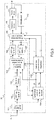
- the figure 3 illustrates a block diagram of the receiver 20 in the case where the transmitted signal is obtained with an SC-FDMA technique with prefix CP. It is assumed here that the signal of the transmitter is synchronized to the receiver with adequate accuracy (ie less than the duration of the CP, if present) and that a synchronization algorithm has provided the synchronization time to the receiver. The signal supplied as input to the block 101 is therefore already synchronized in time and frequency and at the right sampling frequency.
- the receiver can be used to receive a SS-SC-FDMA type signal.
- this receiver can be used in an SC system with CP.
- the receiver can be used to receive a SS-SC type signal.
- the "CP suppression" block is substituted by a "Processing block extraction” block which extracts the known sequences (for example to use them to estimate the channel) and the blocks of data to be processed, then the receiver can receive SC signals and SS-SC with known pilot sequences in place of CPs and CSs.
- the receiver is adapted to receive an OFDM or OFDMA type signal.
- the receiver according to the invention contains two feedback loops.
- the first loop is positioned between the DFE equalizer 108 and the SISO 105 soft demodulator.
- the course of this loop is called “self-iteration” and an equalizer that uses this loop is a “self-iterated equalizer”.
- the second loop is located between the soft demodulator SISO 105 and the decoding block decoder 111.
- the path of this loop is referred to as the "turbo-iteration” and an equalizer that uses this loop is a " turbo-iterated equalizer "or a" turbo-equalizer ".
- the invention realizes a self-iterated equalizer, of the DFE type, which is typically used with a priori null information at the level of the flexible demodulator.
- the numbers of auto-iterations or turbo-iterations set the trade-off between performance, computational complexity and required memory within the receiver.
- the equalizer filter ⁇ ( ⁇ , s ) indicates the filter used for turbo-iteration ⁇ and self-iteration s . This said, in the following, to simplify the notation, the apex will not be explicit, and we will implicitly refer to the current turbo-iteration and auto-iteration.
- the blocks must be initialized at the beginning of the reception processing and at the beginning of each turbo-iteration, so for each
- the data blocks After extracting the data blocks from the receiving antenna A r of the receiver, by deleting the CP in the case of SC systems with CP or SC-FDMA, 101, the data blocks pass through a Fast Fourier Transform (FFT) of size N (frequency domain transition).
- FFT Fast Fourier Transform
- the signal at the output of the FFT then goes into a block "De-alloc sub-p" 103 which makes it possible to access the M frequency resources (sub-carriers) among N, through which the signal has been transmitted.
- This block selects only the sub-carriers on which the signal has been transmitted (de-allocation of the sub-carriers), and at the output of this last dis-allocation block 103 the signal is represented by a vector y of size M, grouping the subcarriers used.
- the pilot sequences are extracted from the signals coming from the reception antenna A r and sent to the block "Estimation of the channels and the variance of the noise” 104. They are used to calculate an estimate of the frequency response of the channel between the transmitter and the receiver, on the M sub-carriers of interest (those used by the user to send the information).
- the block "Estimation of the channels and noise variance "104 also provides an estimate of the variance of noise. This noise contains the contribution of thermal noise on the receiving antenna A r and possible interference due to several spurious effects from either digital processing or other external signals.
- the block "Estimation of the channels and the variance of the noise” provides the covariance matrix of the noise in the frequency domain ⁇ w . Typically, there is a noise channel and covariance estimate per block of data.
- the deinterleaver block 110 is not calculated during the initialization phase.
- the estimate of the channel H and the estimate of the covariance matrix of the noise are then transmitted to the block "calculation of the parameters of the equalizer" 106.
- This block also takes as input the quantity v from the flexible demapping which measures the average reliability of the symbols sent by the user inside the data block which is being processed (the average is thus on the length of block M in the case of the example) .
- the "equalizer parameter calculation" block 106 outputs at each self-iteration the coefficients of the equalizer f of size M in the frequency domain, which is general a self-iterated linear MMSE turbo-equalizer with EP feedback.
- ⁇ m are the coefficients of the filter f .
- the received signal vector y of size M is passed into the block "linear interference suppression equalizer” 108 which also takes the coefficients of the filter of the equalizer ⁇ , the frequency response of the channel H and the size vector M soft estimates of symbols emitted in the frequency domain x , which is generated by the normalized FFT block of size M 107 from the vector of size M of flexible estimates in the time domain x , from the SISO 105 soft demodulator.
- the overall reliability of this estimate is represented by the value v the closer it is to zero, the greater the reliability ( v is a variance).
- the interference canceling linear equalizer block 108 performs Interference Cancellation (IC) for the ISI, in this case SISO.
- IC Interference Cancellation
- the interference canceling linear equalizer block 108 produces a vector of size M x which represents an estimate of the symbols in the frequency domain.
- the vector x is then passed back into the time domain through a standardized IFFT 109 of size M, to obtain the vector x of the equalized time signal, which is sent to the soft demodulator SISO 105.
- the soft demodulator From x , the variance of the noise after equalization ⁇ ⁇ 2 and a priori soft information, for example in the form of Log Likelihood Ratio (LLRs) L a metrics from the decoder, the soft demodulator produces soft information for each bit of the input signal, for example in the form of extrinsic LLR L e .
- LLRs Log Likelihood Ratio
- This demodulator takes different forms according to the statistics of the signal after equalization: if the starting constellation is real one can use a demodulator for symmetric complex Gaussian statistics, otherwise a demodulator for Gaussian statistics with non-zero pseudo-covariance is more suitable.
- the soft metrics are then deinterleaved by the de-interleaver block 110 which is the inverse block of the interleaver block 112. Then, when all the bits of the packet are retrieved, the soft metrics are sent to the decoder 111 which generates, produces bit probabilities estimates sent information (for example, posterior probabilities). These probability estimates can be used to obtain a hard estimate b ' of transmitted bits b with a threshold detector. If the receiver uses turbo-iterations, the decoder also produces estimates of the sent coded bits, ie extrinsic probabilities (EXT), for example in the form of LLRs, which measure the probability that the coded bits sent 0 or 1.
- EXT ie extrinsic probabilities
- the EXTs are then sent to the interleaver 112 to be interleaved.
- the interleaver 112 located in the receiver 20 operates in the same manner as the interleaver 12 in the transmitter 10, with the only difference that it operates on binary data, while the interleaver 112 operates on LLRs .
- the interlaced EXTs become information a priori from the point of view of the rest of the receiver, for example in the form of LLRs a priori L a and enter the flexible demodulator SISO 105.
- SISO 105 the flexible demodulator
- the interference canceling linear equalizer block 108 performs interference suppression and applies linear frequency equalization to the input signal.
- linear equalizer with interference suppression Linear Equalizer - Interference Cancellation - LE-IC
- This structure is already well known in the literature [2].
- the difference from the existing state of the art is in the value of the input x (estimation of symbols in the frequency domain) supplied to block 108, as well as the filter used, these two quantities being calculated in a new way.
- the output x of the interference canceling linear equalizer block 108 will therefore be different than that which can be found in [2] equal to the other hypotheses.
- the figure 4 provides a detailed example for the filtering and the interference removal method, which is efficiently performed as follows.
- the block "linear equalizer interference suppression" 108 comprises a subtractor 201 which acts on vectors of size M and which subtracts from the actually received signal y, an estimate of this same received signal (useful signal with interference of the propagation channel) .
- This allows to obtain a corrective signal input into a linear filter 202 MMSE type of frequency response ⁇ , calculated by the calculation block of the equalizer settings 106.
- the linear filter 202 is itself followed by a summer 203 vectors of size M, which reintroduces into the filtered corrective signal the contribution of the useful signal already estimated.
- the retrenchment block of the estimated received signal 201 obtains the estimate to be subtracted by a generation module of the estimated received signal (useful signal with interference of the propagation channel) 200.
- the summator 201 implements a retrenchment in the frequency domain of the received signal estimated at the received signal, y - h ⁇ x . The result is named corrective signal.
- Block 202 simply applies the filter f .
- This again is simply a multiplication entered by input of the vector of the filter size M and the input vector of the same size. This step corresponds to the equalization itself which further reduces the residual ISI of the corrective signal.
- the structure of the SISO 105 soft demodulator is illustrated in FIG. figure 5 .
- a constellation potentially multidimensional, here the invention is presented with a constellation with a complex dimension
- the modulator in the transmitter 10 from each vector of q bits coded and interleaved at the output of the interleaver block 12, generates the corresponding symbol of the constellation according to a function , which is also called function labeling or simply labeling, a concept known to those skilled in the art.
- d m [ d mq , ..., d ( m + 1 ) q- 1 ] is the m- th group of q elements of the vector d which is the vector of coded and interleaved bits of size qM corresponding to the block of data.
- the bit vector d m can be interpreted as the binary tag of the symbol x m .
- the figure 5 describes a detailed example for the structure of the soft demodulator.
- the at ⁇ d represents the vector of the LLRs a priori on the coded and interleaved bits, coming from the decoder and which are associated with the estimated signal vector after equalization x ( ⁇ , s ) being processed.
- L a ( d ) is a vector of zeros (no prior information on the available bits d ).
- the computation chain constituted by a calculation block of the a priori distributions 300, a block of soft estimates 301, an averaging estimator averaging 302 and a switch 303 is activated.
- This calculation chain is no longer activated for the other indices s ⁇ 0, but only when a new initialization is learned. During the initialization phase, in normal operation the other blocks are not activated.
- the calculation block of prior distributions 300 performs the computation of mass probabilities (probability distributions) a priori on the symbols of the constellation (this block is known from the state of the art) from L a ( d ) .
- mass probabilities probability distributions
- a priori on the symbols of the constellation (this block is known from the state of the art) from L a ( d ) .
- the soft estimate block 301 calculates an estimate of the transmitted symbols, as well as an estimation of their reliability, starting from the input probability distributions. Since all the distributions a priori P m ⁇ ⁇ (for all the symbols of all the data blocks composing the same code word) changes only with each turbo-iteration, block 301 is applied to P m ⁇ ⁇ only once per turbo-iteration and produces the following estimates: with the standard definitions of hope E P m ⁇ ⁇ and variance Var P m ⁇ ⁇ .
- switch 303 If s ⁇ 0, switch 303 outputs the symbol estimates x ⁇ m ⁇ , s + 1 and their average variance v ( ⁇ , s +1) from the adaptive smoothing block 307.
- s -1
- the output of the switch 303 therefore corresponds to the output of a flexible mapping with soft information from of the decoder, as described in reference [2].
- the exit The e ⁇ d is not calculated during the initialization phase. Once the outputs of the switch 303 are calculated, it is assumed that the input index s is incremented by 1.
- the processing chain consisting of blocks 304, 305, 301, 302, 306, 307 and 303.
- the likelihood calculation block 304 calculates likelihoods from the estimates x ⁇ m ⁇ s (the M equalized symbols of the current block) and the residual noise variance after equalization ⁇ v 2 ⁇ s , using an unbiased Gaussian model for estimates x ⁇ m ⁇ s . Note that it is described in the state of the art how to use a biased Gaussian model. This calculation gives: The m ⁇ s x ⁇ m ⁇ s
- the posterior probability distribution calculation block 305 comprises a first non-normalized posterior probability distribution calculation block 305A and a second block 305B whose function is to normalize the values supplied to its input in such a way that the output is a true probability distribution (see Fig. 5 ).
- the non-normalized posterior probability distribution block 305A calculates the distributions of the transmitted symbols by knowing observation (equalized symbols), according to a method known to those skilled in the art: where ⁇ is one of the possible symbols of the constellation .
- the block of soft estimates 301 calculates the estimates ⁇ m ⁇ s and the average variance ⁇ ( ⁇ , s ) symbols using as input a probability distribution obtained by normalizing (305B, equation (10)) the Gaussian likelihoods obtained by an exact or approximated calculation technique (304).
- the new estimation of the emitted symbols, generated by combining the a priori information available with the information contained in the observation according to the invention has characteristics superior to the estimate a priori. , or an estimate derived from the single observation.
- this operation also makes it possible to project a mixed probabilistic description on the sent symbols (Gaussian variables for the observations, combined with a priori estimates which are categorical variables) on a single probabilistic description, according to a Gaussian model as described in reference [3].
- Reverse I-projection or “M-projection” which states that finding an exponential-type distribution ( in our case, Gaussian) which minimizes the divergence of Kullback-Leibler (a measure of probabilistic distance) with respect to any distribution, amounts to finding the exponential distribution having the same statistical moments ("moment matching").
- the posterior mean variance allows both a more robust estimator of the average reliability of the estimated transmitted symbols of the data block and also the ability to implement a Frequency domain equalization strategy, generally less expensive from a computational point of view.
- Post hoc estimates ⁇ m ⁇ s Emitted symbols and their posterior average variances ⁇ ( ⁇ , s ) are then sent to the "Gaussian division" block 306 which also takes as input the observations (equalized symbols) x ⁇ m ⁇ s and the variance of residual noise after equalization ⁇ v 2 ⁇ s which gives a measure of the reliability of these observations.
- the Gaussian division using estimates as averages and reliabilities as variances, associates with each symbol two functions of Gaussian probability density, one for the posterior estimates and the other for the observations, divides them between it and the norms in order to obtain a third Gaussian probability distribution function having as a mean a new flexible estimate of the transmitted signal x ⁇ ' m ⁇ , s + 1 , and as variance the corresponding measure of reliability per block of data v ' ( ⁇ , s +1) .
- this block will generate an extrinsic information on the emitted symbols, following a Gaussian model.
- the solutions of the state of the art use either a priori information (categorical, extrinsic of the decoder), or a posteriori information (also categorical, combined extrinsic information of the decoder and the likelihood of the flexible demodulator).
- This operation therefore makes it possible to better respect the turbo principle by subtracting from the information a posteriori, the information a priori available to the demodulator, at the beginning of the processing (it is the extrinsic of the equalizer) and thus allowing improve the quality of the feedback signal and, ultimately, the performance of the receiver.
- the block 306 may output as a priori information from the decoder, calculated at the initialization of the flexible demodulator SISO (not shown in FIG. figure 5 ), as well as the average variance associated with the a priori as reliability. Still other strategies in the same case are to set the output variance v ' ( ⁇ , s +1) has an arbitrary value prefixed for each ⁇ and s .
- extrinsic estimates are passed to the adaptive smoothing block 307 whose purpose is to smooth the input estimates by taking past values into account.
- the z -1 blocks that are on the loop, in the figure 5 represent the operation of unit delay, vis-à-vis the index s , with reference to the transform Z.
- ⁇ a null function
- ⁇ (.) which remains constant, close to one, during the initial few iterations, then decreases linearly after deciding that the erroneous fixed points will not be fixed. taken into account.
- adaptive filters for example of the Kalman type.
- Yet another method is to dynamically read the parameters ⁇ ⁇ , s in a pre-filled table and stored in the memory of the equipment.
- pre-filled values of the parameters ⁇ ⁇ , s can be indexed according to one or more parameters of the receiver (for example the index of the current self-iteration or the current turbo-iteration) or of one or more metrics that the receiver can measure, such as the estimated channel, the noise estimate or the reliability of the returns of the decoder for example, and then use their values to dynamically choose the values of the corresponding ⁇ ⁇ , s .
- the adaptive smoothing block 307 generates extrinsic smoothed estimates.
- the SISO 105 soft demodulator After performing SISO 105 soft demodulation, the decoding process will be initiated. In this case, the SISO 105 soft demodulator outputs, for each new turbo-iteration with the decoder, extrinsic LLRs. The e ⁇ d on the coded bits of the processed data block. In this phase, the switch block 308 is closed and only the block 309 and the adder 310 are used. It is not necessary to calculate the other outputs of block 105.
- the The e ⁇ d are generated from the posterior LLRs calculated by block 309 and subtracting LLRs a priori The at ⁇ d through block sum 310.
- the block of calculation of posterior LLRs 309 is a known block of literature: Other logarithmic bases and methods of simplification of calculations are also applicable.
- the figures 6 and 7 illustrate an exemplary performance of the invention in a case of SC system with synchronization and perfect channel estimation, in the SISO framework.
- the constellation used by the transmitter is an 8-PSK
- the propagation channel is the Proakis C channel (with average power normalized to one) with a power profile of the type triangular (1, 2, 3, 2, 1).
- the figure 6 in particular shows the performance with without turbo-iteration, and with turbo-iterating once with decoder. In both cases the gains are considerable.
- FIG. 7 illustrates the performance with turbo iterations.
- the proposals considered come closer to the adapted filter terminal than the linear frequency MMSE turbo-equalizer with IC.
- the invention can be applied to a fractional turbo equalizer, for example see [8].
- the signal from the antenna is oversampled with a factor with a factor o > 1, typically an integer.
- the data blocks will therefore have a size oN in the FFT 102, oM in the inverse IFFT 109 and in the FFT 107.
- the IFFT block 109 is followed by a flow sampler o and the FFT block 107 is preceded by an ideal interpolator of factor o (which introduces o - 1 zero between two incoming samples).
- the "channel estimate and noise variance" block should make its estimates in the interpolated domain including possible transmit and receive filters, and then possibly pass the frequency estimates.
- the calculation of the parameters of the equalizer will carry out the calculations of the filter in the oversampled domain, on the other hand it will estimate the variance of the residual noise of equalization at the symbol time (to pass it to the flexible demodulator).
- the turbo block equalization 108 goes therefore work in the oversampled field.
- the SISO 105 soft demodulation block retains the foregoing description.
- the invention can be applied to an overlap equalizer FDE [9].
- FDE overlap equalizer
- the data block between two pilot sequences is longer than the processing block, and for complexity or necessity issues (for example a time-varying channel that changes in the horizon of a block of data), the frequency equalization process is broken down into several segments (with overlapping) of the initial data block. These segments suffer from interference between them. This implies that the noise covariance matrix at the output of the "channel estimate and noise variance" block 104 also includes the variance due to the interference, which modifies the values of the equalization filter.
- the channel estimate and noise variance block 104 can implement channel estimation and noise variance methods by exploiting this information additional.
- the new channel and noise variance estimates can be exploited by the rest of the receiver as described above.
- the proposed technique can also be applied to linear equalizers in the broad sense.
- the invention can be used within any type of iterative receiver being structured as illustrated in FIG. Figure 8 .
- This estimator extracts the signal y, the pilot sequences, in order to use one of the estimation techniques, known to those skilled in the art, to obtain parameters characterizing the channel.
- the estimate x is obtained through an interference suppression method which, using a prior estimate x the transmitted signal x , and an estimate of the channel parameters, generates an estimate of the interference and subtracts it from the received signal.
- a 503 receiver parameter calculation block is available, which uses the channel estimates and the reliability of the preliminary estimate. v , to calculate the intrinsic parameters of the receiver 502, and to calculate the variance ⁇ v 2 characterizing the residual interference power v at the output of the receiver 502.
- the invention applies at the level of the soft demodulator 504, where, for a data block with supposedly white statistics, the expectation propagation technique is used to calculate the flexible estimates x which will serve as feedback for the receiver, with the variance v characterizing the reliability of these same estimates.
- the soft demodulator 504 calculates extrinsic bit LLRs on the symbol-determining bits that can be used to estimate bits transmitted through a hard decision 505, comparing each binary LLR to zero.
- the soft input / output binary decoder block 507 is used in conjunction with the soft demodulator 504, and the adaptive receiver 502, in an appropriately selected scheduling, to assist in decoding the information bits of the transmitter.
- the two-loop scheduling described above for the SC-FDMA application could be used.
- the blocks of the interleaver 506 and interleaver 508 are included in the iteration loop between the soft demodulator 504 and the decoder 507.
- the estimates can be considered as x and reliability v at the output of the soft demodulator 504 are also directed to the channel estimator 501 (dashed arrows on the figure 8 ).
- the estimator 501 can use, from the first self-iteration of the receiver, the estimate x of the transmitted signal, together with the observation of the y- channel , to refine the parameters of the estimated channel, for example with a "least-squares" method on the entire data block, instead of using only the pilots.
- the invention relates, in particular, to the technique of estimating the transmitted signal, at the level of the flexible demodulator 504 which works on a model equivalent to a Gaussian additive noise.
- She may be used in any iterative receiver that goes through such a demodulation step and differs from hard demodulators, used inter alia in conventional decision feedback equalizers, which are subject to error propagation problems.
- the technique considered here is also different from the flexible demodulation techniques using a posteriori estimation of the signal, which do not remove from the estimation of the signal of return the information already known by the receiver, thus inducing the receiver to the error by biasing it with its own information.
- the method according to the invention provides an average reliability per block of data, which makes the receiver less complex and more robust to errors. one-off estimation.
- the invention applies adaptive smoothing on the estimated signal to provide an additional degree of freedom that allows the ratio of robustness of performance to convergence speed of the receiver to be compared to the limiting performance.
- the invention also applies to the single-user single-input multiple output (SIMO) case, that is to say to a communications system with a single transmitter and a single receiver using R antennas at reception.
- SIMO single-user single-input multiple output
- the invention also applies to the multiple input multiple-output (MIMO) multiple-user case where the single transmitter is provided with several, T u , transmission antennas.
- MIMO multiple input multiple-output
- T u 1
- R can be equal to one or more.
- U users transmit to the receiver and use the same time and frequency resources.
- the system is represented in figure 9 .
- This type of system is also called distributed Multiple Input Multiple Output (MIMO) system or virtual MIMO, or simply MIMO. If these users use separate time and frequency resources, allowing the receiver to see their signals without interference (ie orthogonal), the receiver can treat each of the users as an independent single-user SIMO / SISO system.
- MIMO distributed Multiple Input Multiple Output
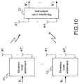
- the invention also applies to a multi-user wireless transmission system, where the users u (10 1 ,... 10 u ) are provided with one or more antennas (T u ⁇ 1) and the receiver 20 is provided with R antennas or R ⁇ 1.
- T u ⁇ 1 the users transmit to the receiver and use the same time and frequency resources.
- the system is represented in figure 10 .
- This type of system is also called Multi-User MIMO system (MU-MIMO). If these users use separate time and frequency resources, allowing the receiver to see their signals without interference (ie orthogonal), the receiver can treat each of the users as an independent single-user Multiple Input Single Output (MISO) system. In this case, only the interference between the antenna signals of the same transmitter will be present or non-negligible.
- MISO Multiple Input Single Output
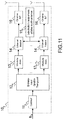
- the figure 11 illustrates the case of a generic multi-antenna transmitter 10 u , and the associated functional block diagram.
- the corrector error coder 11 u used in this case is not subject to constraints different from those of a single-antenna transmitter, it takes input bits of information, and provides encoded bits output.
- the spatio-temporal interleaver 12 provides u T u flow independent interleaved bits output.
- Each of the interleaved bit streams is then modulated by a modulator 13 u, 1 , 13 u, Tu dedicated to each antenna which outputs symbols drawn from a constellation , which can be different from one antenna to another and from one user to another.
- Remarks on the constellations to which the invention is still applicable extends to the case of each of T u modulators of a multi-antenna transmitter.
- the framing blocks 14 organize the symbols using the same strategy for each of the antennas.
- Block 15 u generator pilot sequences is extended to the multi-antenna case, with an ability to provide distinct pilot sequences for different antennas. Examples of given modulations, such as OFDM, (SS) -SC-FDMA or (SS) -SC, remain valid.
- each of the signals prepared for an antenna is passed through a radio frequency chain (RF) 16, identical for each antenna, and transmitted.
- RF radio frequency chain
- the correction code, the interleaver, the modulator and the generation of pilot sequences may have different characteristics chosen according to the user.
- the modulator may have different characteristics chosen according to the transmitting antenna for a given user.
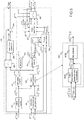
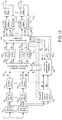
- the figure 12 represents a functional block diagram for the receiver in the case where the transmitted signal is obtained with an SC-FDMA technique with CP.
- this receiver can be used in an SC or SS system -SC or SS-SC-FDMA with CP.
- the receiver is adapted to the different types of SC systems with pilot or constant sequences instead of the CPs. . It is assumed here that the signal of the transmitter is synchronized to the receiver with adequate reliability (ie less than the duration of the CP, if present) and that a synchronization algorithm provided the synchronization instant to the receiver.
- the MU-MIMO receiver of the figure 12 contains two feedback loops: an auto-iteration loop (soft-mount / equalizer iteration) and a turbo-iteration loop (soft-mount / decoder iteration).
- the receiver in the presence of several users, the receiver must decide, for each loop, the users whose signals will be decoded / processed and which signals will not be decoded / processed.
- the groupings of users in the partition can be made according to several possible metrics, for example users scheduled according to the power of reception of their signals, or according to a metric derived from the power of reception of their signals and the reliability / variance of their constellations, or metrics based on differences in reception power and reliability between user pairs, etc.
- This block has all the T signals estimated as input.
- the receiver therefore tries to decode u i having the soft information of decoding already for all u j with j ⁇ i.
- a per-user encoder as in figure 11 .
- the same mechanism can be used to schedule the decoding of the antenna signals of all users together .
- Quantities exchanged by the iterative receiver of the figure 12 generally depend on the index of self-iteration, turbo-iteration and the scheduling of users to decode within a given turbo-iteration (especially users already decoded within the same turbo iteration) .
- the turbo-iteration index is incremented when all users have been decoded (the entire partition of all users has been browsed according to the established order function).
- the equalizer filter f t , u ⁇ i s indicates the filter to be applied to equalize the signal of the antenna t of the user u , which filter is used with the turbo-iteration ⁇ and the self-iteration s , knowing that during the turbo-iteration one wants to decode the users of the set u i and knowing that the users belonging to all u j with j ⁇ i have already been decoded.
- the index of the user u (at the bottom of the symbol) may or may not belong to u i , since it refers to the filter used in the self-iteration loop (no turbo-iteration), which elsewhere follows a parallel processing method described below.
- the index ( ⁇ , u i , s ) will not necessarily be explicit, and we will refer implicitly to the turbo-iteration, to the users being decoded fluently and the current self-iteration.
- the pilot sequences are extracted from the signals from the receiving antenna and sent to the "Estimation of noise channels and variance" block 104 and used to calculate an estimate of the frequency response of the MIMO channels between the receivers. transmitters and the receiver, on the sub-carriers M interest (those used by users to send the information).
- the matrices corresponding to a transmission antenna t of a user u can be concatenated in a diagonal-block matrix H t , u of size MR x M. These can be concatenated sequentially in a block-diagonal matrix H of size MR x MT, the channels of the emitters of the emitters are concatenated on the same line, for the same receiving antenna.
- the "Estimation of channels and noise variance" block 104 also provides an estimate of the variance of noise.
- This noise contains the contribution of the thermal noise on the receiving antennas and any interference due to the several effects from either digital processing or other external signals. It is assumed that the "Estimation of noise channels and variance" block provides the noise covariance matrix in the frequency domain ⁇ w of size MR x MR. Typically, there is a noise channel and covariance estimate per block of data.
- the estimate of the global channel MU-MIMO H and the noise covariance matrix are passed to the "calculation of the equalizer parameters" block 106.
- the equalizer calculated by calculating the parameters of the equalizer 106 coincides with a traditional linear MMSE MU-MIMO equalizer implemented in the frequency domain.
- the equalizer obtained by calculating equalizer 106 coincides with a linear turboequaliser MMSE traditional interference cancellation implemented in the frequency domain (or according to a strategy series or parallel depending on the scheduling of users u decoded during the turbo-iteration).
- the equalizer calculation block 106 outputs at each self-iteration the coefficients of the equalizers f t , u of size MR in the domain frequency, for the equalization of the signal from the antenna t of the user u.
- This filter acts on the concatenated observations y in the frequency domain.
- This is usually a self-iterated linear MMSE turbo-equalizer with EP feedback.
- the receiver must calculate its inverse and there are efficient methods in terms of calculations or memory to implement this calculation.
- the vectors of signals received on antennas and transformed in frequency y r of size M are passed to the block "linear equalizer with suppression of interference" 108 which also receives as input the coefficients of the equalizers F u , for all the users u (which are processed in parallel), the overall frequency response of the MU-MIMO H channel and the M- size vectors of soft estimates of the frequency-domain symbols x u , for all u users , which are generated from the M size vectors of time domain flexible estimates x u , from the MU-MIMO 105T soft demodulator.
- the LE-IC equalizer 108 performs interference suppression (IC) for the ISI, MAI and MUI in the general MU-MIMO case.
- the equalizer 108 produces vectors x t, u of size M which represent estimates of the symbols of each antenna of each user in the frequency domain.
- the vectors x t, u are then passed back into the time domain through IFFT normalized T u of M (109), to obtain vectors x t, u representing the equalized time signals, which are sent to demodulator flexible MU- MIMO 105T.
- the latter from the x t, u , of the corresponding variances of the noise after equalization ⁇ v , t , u 2 and a priori flexible information, for example in the form of Log-Likelihood Ratios (LLRs) L a ( d u ) metrics from the decoders, produces the soft estimates of the symbols emitted in the time domain.
- LLRs Log-Likelihood Ratios
- the soft-keying device also produces flexible information for each bit of the signals of the users belonging to u i , for example in the form of extrinsic LLRs L e ( d u ), u ⁇ u i .
- the soft metrics L e ( d u ), u ⁇ u i are then deinterleaved by the blocks 110 u for users u ⁇ u i . Then, the soft metrics are sent to decoders 111 u of users u ⁇ u i that produce estimates of the probabilities of the bits of information sent (eg, posterior probabilities), if the last turbo-iteration is reached, ie They are used to decide which bits are sent with threshold detectors.
- the decoders 111 u of the users u ⁇ u i also produce estimates of the sent coded bits, that is to say extrinsic probabilities (EXT), for example in the form of LLRs, which measure the probability that the coded bits sent 0 and 1.
- EXT extrinsic probabilities
- the EXTs are then sent to the interleavers 112 u of the users u ⁇ u i .
- the interleaved EXTs of the users u ⁇ u i become a priori information L a ( d u ) and enter the soft demodulator MU-MIMO 105T.
- the MU-MIMO 105T soft demodulator processes its inputs and the continuous procedure according to the activation of an auto-iteration or a turbo-iteration.
- the interference canceling linear equalizer block 108 performs interference suppression (IC) for the ISI, MAI, and MUI and equalizes the received signals in the frequency and space domain.
- IC interference suppression
- the difference with the state of the art exists in the entries x u (estimates of symbols in the frequency domain for all users), as well as the filters used, these quantities being calculated according to the method of the invention.
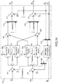
- the figure 14 describes in detail the filtering and the method of suppressing the interference.
- the concatenation block 204 simply serves to concatenate the vectors of the soft estimates x u of size MT u in a single vector x of size MT.
- the block "Generation of estimated received signals" 205 generates an estimate of the R received signals (useful part plus any interference of the type) to the receiver, concatenated in the output vector H x of size MR.
- x is a vector of zeros (no estimate available).
- the separator 206 separates the vector H x in R vectors of size M , one for each channel of the receiver.
- the concatenation blocks 210 u concatenate together the signals of the T u antennas of the same user u.
- the vector sums 211 u generate the frequency estimates (of size T u M ) of the equalized symbols by adding the estimates of the useful signals to the filtered correction signals coming from the banks of filters 208, as a generalization of the sums from the block 201 to SISO case.
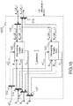
- the MU-MIMO 105T soft demodulator represented in figure 13 , Consists of flexible U demodulators MIMO separated 105T u, which separately treat the equalized signals corresponding to the same user transmission antennas.
- the scheduling and initialization manager 311 ( figure 13 ) activates all MIMO soft demodulators during self-iterations, thus generating all soft estimates x u and their corresponding average reliability v u so that the blocks implementing the interference cancel equalization functions can have signal estimates of all users.
- the scheduling manager configures only the MIMO soft demodulators of the users u ⁇ u i which must be decoded according to the current scheduling so that these demodulators calculate the extrinsic LLRs L e ( d u ) to be sent to the decoders of the interested users.
- the manager 311 will trigger the initialization of the soft demodulators MIMO 105T u according to the chosen strategy ( see description above for the MU-MIMO turbo-receiver figure 12 ).
- the soft demodulator MIMO 105T is composed of u T u flexible SISO demodulator 105 already described (see figure 5 ) which are all activated at the same time by the command from the scheduling and initialization manager 311 ( figure 13 ).
- Each flexible SISO demodulator 105 processes the data vectors corresponding to one of the transmission antennas of the user u, using its corresponding constellation ⁇ t , u .
- the separation block 113 deconcatens the vector ⁇ v , u 2 of size T u residual noise variances, in T u values ⁇ v , t , u 2 to send to the demodulators.
- the separation block 114 deconcatens the vector x u representing signals after equalization and interference suppression of size MT u , T u vectors x t, u to be sent to the demodulators.
- the separation block 115 deconcatenates the vector L a ( d u ) representing the LLRs a priori from the decoder of the user u and of size equal to the sum of the length of the packets coded on the T u antennas of the user.
- T vectors u L (d t, u) representing the a priori LLRs of the packet sent on antenna T of the user u, to be sent to the demodulators.
- the concatenation devices 116, 117, 118 operate in the opposite way to the blocks 113, 114, 105, respectively on Reliability v t, u , flexible estimates of symbols issued x t, u and extrinsic LLRs L e ( d t, u ) to form vectors v u , x u and L e ( d u ).
- a single MIMO 105T soft demodulator block u is used at the MIMO receiver, and the symbols transmitted are denoted x t , 1 , with the corresponding code word d 1 .
- the invention is also applied trivially to those skilled in the art in schemes with orthogonal block-type space-time codes, such as that of Alamouti and described for SC-FDMA in article [12] , for example. These diagrams are not represented.
- orthogonal block-type space-time codes there are detection methods known to those skilled in the art [12] with maximum likelihood or with a posterior probability maximum with reduced complexity.
- the invention described here can be applied after having adapted the calculations of the interference canceling linear equalization block 502 and the calculation block of the parameters of the receiver 503, for example as described in [12] so as to take into account counts the structure of the space-time code in blocks of orthogonal type used at the transmitter.
Landscapes
- Engineering & Computer Science (AREA)
- Power Engineering (AREA)
- Computer Networks & Wireless Communication (AREA)
- Signal Processing (AREA)
- Physics & Mathematics (AREA)
- Probability & Statistics with Applications (AREA)
- Radio Transmission System (AREA)
Priority Applications (1)
| Application Number | Priority Date | Filing Date | Title |
|---|---|---|---|
| PL19156763T PL3528443T3 (pl) | 2018-02-15 | 2019-02-12 | Sposób obliczania estymacji modulowanego sygnału cyfrowego i jego niezawodności |
Applications Claiming Priority (1)
| Application Number | Priority Date | Filing Date | Title |
|---|---|---|---|
| FR1800146A FR3077941A1 (fr) | 2018-02-15 | 2018-02-15 | Procede pour calculer une estimation d'un signal numerique module et de sa fiabilite |
Publications (2)
| Publication Number | Publication Date |
|---|---|
| EP3528443A1 true EP3528443A1 (de) | 2019-08-21 |
| EP3528443B1 EP3528443B1 (de) | 2020-09-09 |
Family
ID=62167449
Family Applications (1)
| Application Number | Title | Priority Date | Filing Date |
|---|---|---|---|
| EP19156763.5A Active EP3528443B1 (de) | 2018-02-15 | 2019-02-12 | Verfahren zum berechnen eines schätzwerts eines modulierten digitalen signals und seiner zuverlässigkeit |
Country Status (4)
| Country | Link |
|---|---|
| EP (1) | EP3528443B1 (de) |
| ES (1) | ES2833540T3 (de) |
| FR (1) | FR3077941A1 (de) |
| PL (1) | PL3528443T3 (de) |
Cited By (6)
| Publication number | Priority date | Publication date | Assignee | Title |
|---|---|---|---|---|
| CN112104580A (zh) * | 2020-09-11 | 2020-12-18 | 中海石油(中国)有限公司湛江分公司 | 基于广义近似消息传递-稀疏贝叶斯学习的稀疏水声信道估计方法 |
| FR3157998A1 (fr) | 2023-12-28 | 2025-07-04 | Thales | Procédé de calcul d'une table de correspondance permettant la mise en oeuvre efficace d'un modulateur souple dans un récepteur turbo |
| FR3157999A1 (fr) | 2023-12-28 | 2025-07-04 | Thales | Procédé de calcul d'une table de correspondance entre une variance d'échantillons d'entrée d'un démodulateur souple et une variance associée à des LLR bits a priori dans un récepteur turbo |
| FR3157997A1 (fr) | 2023-12-28 | 2025-07-04 | Thales | Procédé d'estimation d'un signal de retour souple dans un récepteur turbo basé sur la propagation d'espérance |
| CN121367478A (zh) * | 2025-12-22 | 2026-01-20 | 苏州大学 | 量化感知宽线性最小误差模自适应滤波器 |
| CN121508553A (zh) * | 2026-01-14 | 2026-02-10 | 电子科技大学 | 一种基于干扰抑制的Hadamard-LDPC迭代译码方法 |
Families Citing this family (1)
| Publication number | Priority date | Publication date | Assignee | Title |
|---|---|---|---|---|
| CN115167391B (zh) * | 2022-06-14 | 2024-10-15 | 北京交通大学 | 一种基于滑模控制的虚拟编组列车编队控制方法 |
-
2018
- 2018-02-15 FR FR1800146A patent/FR3077941A1/fr not_active Withdrawn
-
2019
- 2019-02-12 PL PL19156763T patent/PL3528443T3/pl unknown
- 2019-02-12 EP EP19156763.5A patent/EP3528443B1/de active Active
- 2019-02-12 ES ES19156763T patent/ES2833540T3/es active Active
Non-Patent Citations (2)
| Title |
|---|
| SANTOS IRENE ET AL: "Block expectation propagation equalization for ISI channels", 2015 23RD EUROPEAN SIGNAL PROCESSING CONFERENCE (EUSIPCO), EURASIP, 31 August 2015 (2015-08-31), pages 379 - 383, XP032836367, DOI: 10.1109/EUSIPCO.2015.7362409 * |
| WU KUN ET AL: "Spectral-Efficient Band Allocation Scheme for Frequency-Domain Pulse-Shaping-Based SC-FDMA Systems", IEEE TRANSACTIONS ON VEHICULAR TECHNOLOGY, IEEE SERVICE CENTER, PISCATAWAY, NJ, US, vol. 66, no. 9, 1 September 2017 (2017-09-01), pages 8249 - 8262, XP011660834, ISSN: 0018-9545, [retrieved on 20170919], DOI: 10.1109/TVT.2017.2683802 * |
Cited By (6)
| Publication number | Priority date | Publication date | Assignee | Title |
|---|---|---|---|---|
| CN112104580A (zh) * | 2020-09-11 | 2020-12-18 | 中海石油(中国)有限公司湛江分公司 | 基于广义近似消息传递-稀疏贝叶斯学习的稀疏水声信道估计方法 |
| FR3157998A1 (fr) | 2023-12-28 | 2025-07-04 | Thales | Procédé de calcul d'une table de correspondance permettant la mise en oeuvre efficace d'un modulateur souple dans un récepteur turbo |
| FR3157999A1 (fr) | 2023-12-28 | 2025-07-04 | Thales | Procédé de calcul d'une table de correspondance entre une variance d'échantillons d'entrée d'un démodulateur souple et une variance associée à des LLR bits a priori dans un récepteur turbo |
| FR3157997A1 (fr) | 2023-12-28 | 2025-07-04 | Thales | Procédé d'estimation d'un signal de retour souple dans un récepteur turbo basé sur la propagation d'espérance |
| CN121367478A (zh) * | 2025-12-22 | 2026-01-20 | 苏州大学 | 量化感知宽线性最小误差模自适应滤波器 |
| CN121508553A (zh) * | 2026-01-14 | 2026-02-10 | 电子科技大学 | 一种基于干扰抑制的Hadamard-LDPC迭代译码方法 |
Also Published As
| Publication number | Publication date |
|---|---|
| ES2833540T3 (es) | 2021-06-15 |
| PL3528443T3 (pl) | 2021-03-08 |
| FR3077941A1 (fr) | 2019-08-16 |
| EP3528443B1 (de) | 2020-09-09 |
Similar Documents
| Publication | Publication Date | Title |
|---|---|---|
| EP3528443B1 (de) | Verfahren zum berechnen eines schätzwerts eines modulierten digitalen signals und seiner zuverlässigkeit | |
| EP2947799B1 (de) | Verfahren zur im weiteren sinne linearen turboentzerrung in einem system mit mehreren nutzern und für einen mehrantennen-empfänger | |
| EP1658694B1 (de) | Iteratives decodierungs- und entzerrungsverfahren und vorrichtung für kommunikation mit mehreren sende- und empfangsantennen | |
| EP2220803B1 (de) | Störminderung bei einem ofdm-signal mit gewichtungsvektorbildung in untervektorräumen | |
| EP3800813B1 (de) | Verfahren und vorrichtung zur vorhersage der leistungen eines empfängers in einem kommunikationssystem | |
| EP2274852A2 (de) | Verfahren zur dekodierung eines signals mit progressivem aufbau eines dekodierbaums, entsprechendes computerprogrammprodukt und dekodiergerät | |
| EP1589685B1 (de) | Iterative Chipentzerrung und Mehrbenutzerdetektion in CDMA Kommunikationssystemen durch MIMO Kanal | |
| FR2893433A1 (fr) | Procedes et dispositifs de demodulation souple dans un systeme ofdm-cdma. | |
| EP1603264B1 (de) | Verfahren und Gerät zum Empfang von einem linear vorkodierten und kanalkodierten Signal | |
| EP1589672B1 (de) | Iterative Vektoregalisierungsverfahren für CDMA-Kommunikationssysteme über MIMO-Kanal | |
| EP1661286A1 (de) | Empfänger und verfahren zur dekodierung eines signals, kodiert mit hilfe einer raumzeitkodierungsmatrix | |
| EP1856871A1 (de) | Verfahren für den wiederholten empfang eines mehrträgersignals mit interferenzunterdrückung, entsprechender empfänger und computerprogramm | |
| EP1589673B1 (de) | Iterative Mehrbenutzerdetektionsverfahren für CDMA-Kommunikationssysteme über MIMO-Kanal | |
| EP1999918B1 (de) | Verfahren und Einrichtung zum Empfangen eines aus Symbolblöcken bestehenden Datensignals und entsprechendes Computerprogramm | |
| EP1221206A1 (de) | Verfahren und vorrichtung zur demodulation von mehrebenutzersignalen | |
| FR2849306A1 (fr) | Recepteur a turbo-estimation de canal a convergence optimisee | |
| Petitpied | Faster-Than-Nyquist communication systems: from single-carrier to multi-carrier signaling | |
| WO2023213962A1 (en) | Continuous phase modulation receiver | |
| WO2016020611A1 (fr) | Procede et dispositif de reception de signaux | |
| CA2389592A1 (fr) | Procede et dispositif pour ordonner des signaux provenant de multi-utilisateurs | |
| Dietl | System Model for Iterative Multiuser Detection |
Legal Events
| Date | Code | Title | Description |
|---|---|---|---|
| PUAI | Public reference made under article 153(3) epc to a published international application that has entered the european phase |
Free format text: ORIGINAL CODE: 0009012 |
|
| STAA | Information on the status of an ep patent application or granted ep patent |
Free format text: STATUS: THE APPLICATION HAS BEEN PUBLISHED |
|
| AK | Designated contracting states |
Kind code of ref document: A1 Designated state(s): AL AT BE BG CH CY CZ DE DK EE ES FI FR GB GR HR HU IE IS IT LI LT LU LV MC MK MT NL NO PL PT RO RS SE SI SK SM TR |
|
| AX | Request for extension of the european patent |
Extension state: BA ME |
|
| STAA | Information on the status of an ep patent application or granted ep patent |
Free format text: STATUS: REQUEST FOR EXAMINATION WAS MADE |
|
| 17P | Request for examination filed |
Effective date: 20200217 |
|
| GRAP | Despatch of communication of intention to grant a patent |
Free format text: ORIGINAL CODE: EPIDOSNIGR1 |
|
| RBV | Designated contracting states (corrected) |
Designated state(s): AL AT BE BG CH CY CZ DE DK EE ES FI FR GB GR HR HU IE IS IT LI LT LU LV MC MK MT NL NO PL PT RO RS SE SI SK SM TR |
|
| STAA | Information on the status of an ep patent application or granted ep patent |
Free format text: STATUS: GRANT OF PATENT IS INTENDED |
|
| RIC1 | Information provided on ipc code assigned before grant |
Ipc: H04L 25/06 20060101ALI20200306BHEP Ipc: H04L 25/03 20060101AFI20200306BHEP |
|
| INTG | Intention to grant announced |
Effective date: 20200326 |
|
| GRAS | Grant fee paid |
Free format text: ORIGINAL CODE: EPIDOSNIGR3 |
|
| GRAA | (expected) grant |
Free format text: ORIGINAL CODE: 0009210 |
|
| STAA | Information on the status of an ep patent application or granted ep patent |
Free format text: STATUS: THE PATENT HAS BEEN GRANTED |
|
| AK | Designated contracting states |
Kind code of ref document: B1 Designated state(s): AL AT BE BG CH CY CZ DE DK EE ES FI FR GB GR HR HU IE IS IT LI LT LU LV MC MK MT NL NO PL PT RO RS SE SI SK SM TR |
|
| REG | Reference to a national code |
Ref country code: GB Ref legal event code: FG4D Free format text: NOT ENGLISH |
|
| REG | Reference to a national code |
Ref country code: AT Ref legal event code: REF Ref document number: 1312960 Country of ref document: AT Kind code of ref document: T Effective date: 20200915 Ref country code: CH Ref legal event code: EP |
|
| REG | Reference to a national code |
Ref country code: DE Ref legal event code: R096 Ref document number: 602019000579 Country of ref document: DE |
|
| REG | Reference to a national code |
Ref country code: IE Ref legal event code: FG4D Free format text: LANGUAGE OF EP DOCUMENT: FRENCH |
|
| REG | Reference to a national code |
Ref country code: FI Ref legal event code: FGE |
|
| REG | Reference to a national code |
Ref country code: LT Ref legal event code: MG4D |
|
| PG25 | Lapsed in a contracting state [announced via postgrant information from national office to epo] |
Ref country code: GR Free format text: LAPSE BECAUSE OF FAILURE TO SUBMIT A TRANSLATION OF THE DESCRIPTION OR TO PAY THE FEE WITHIN THE PRESCRIBED TIME-LIMIT Effective date: 20201210 Ref country code: LT Free format text: LAPSE BECAUSE OF FAILURE TO SUBMIT A TRANSLATION OF THE DESCRIPTION OR TO PAY THE FEE WITHIN THE PRESCRIBED TIME-LIMIT Effective date: 20200909 Ref country code: BG Free format text: LAPSE BECAUSE OF FAILURE TO SUBMIT A TRANSLATION OF THE DESCRIPTION OR TO PAY THE FEE WITHIN THE PRESCRIBED TIME-LIMIT Effective date: 20201209 Ref country code: NO Free format text: LAPSE BECAUSE OF FAILURE TO SUBMIT A TRANSLATION OF THE DESCRIPTION OR TO PAY THE FEE WITHIN THE PRESCRIBED TIME-LIMIT Effective date: 20201209 Ref country code: HR Free format text: LAPSE BECAUSE OF FAILURE TO SUBMIT A TRANSLATION OF THE DESCRIPTION OR TO PAY THE FEE WITHIN THE PRESCRIBED TIME-LIMIT Effective date: 20200909 Ref country code: SE Free format text: LAPSE BECAUSE OF FAILURE TO SUBMIT A TRANSLATION OF THE DESCRIPTION OR TO PAY THE FEE WITHIN THE PRESCRIBED TIME-LIMIT Effective date: 20200909 |
|
| REG | Reference to a national code |
Ref country code: AT Ref legal event code: MK05 Ref document number: 1312960 Country of ref document: AT Kind code of ref document: T Effective date: 20200909 |
|
| REG | Reference to a national code |
Ref country code: NL Ref legal event code: MP Effective date: 20200909 |
|
| PG25 | Lapsed in a contracting state [announced via postgrant information from national office to epo] |
Ref country code: LV Free format text: LAPSE BECAUSE OF FAILURE TO SUBMIT A TRANSLATION OF THE DESCRIPTION OR TO PAY THE FEE WITHIN THE PRESCRIBED TIME-LIMIT Effective date: 20200909 Ref country code: RS Free format text: LAPSE BECAUSE OF FAILURE TO SUBMIT A TRANSLATION OF THE DESCRIPTION OR TO PAY THE FEE WITHIN THE PRESCRIBED TIME-LIMIT Effective date: 20200909 |
|
| PG25 | Lapsed in a contracting state [announced via postgrant information from national office to epo] |
Ref country code: EE Free format text: LAPSE BECAUSE OF FAILURE TO SUBMIT A TRANSLATION OF THE DESCRIPTION OR TO PAY THE FEE WITHIN THE PRESCRIBED TIME-LIMIT Effective date: 20200909 Ref country code: PT Free format text: LAPSE BECAUSE OF FAILURE TO SUBMIT A TRANSLATION OF THE DESCRIPTION OR TO PAY THE FEE WITHIN THE PRESCRIBED TIME-LIMIT Effective date: 20210111 Ref country code: RO Free format text: LAPSE BECAUSE OF FAILURE TO SUBMIT A TRANSLATION OF THE DESCRIPTION OR TO PAY THE FEE WITHIN THE PRESCRIBED TIME-LIMIT Effective date: 20200909 Ref country code: CZ Free format text: LAPSE BECAUSE OF FAILURE TO SUBMIT A TRANSLATION OF THE DESCRIPTION OR TO PAY THE FEE WITHIN THE PRESCRIBED TIME-LIMIT Effective date: 20200909 Ref country code: SM Free format text: LAPSE BECAUSE OF FAILURE TO SUBMIT A TRANSLATION OF THE DESCRIPTION OR TO PAY THE FEE WITHIN THE PRESCRIBED TIME-LIMIT Effective date: 20200909 |
|
| PG25 | Lapsed in a contracting state [announced via postgrant information from national office to epo] |
Ref country code: AL Free format text: LAPSE BECAUSE OF FAILURE TO SUBMIT A TRANSLATION OF THE DESCRIPTION OR TO PAY THE FEE WITHIN THE PRESCRIBED TIME-LIMIT Effective date: 20200909 Ref country code: AT Free format text: LAPSE BECAUSE OF FAILURE TO SUBMIT A TRANSLATION OF THE DESCRIPTION OR TO PAY THE FEE WITHIN THE PRESCRIBED TIME-LIMIT Effective date: 20200909 Ref country code: IS Free format text: LAPSE BECAUSE OF FAILURE TO SUBMIT A TRANSLATION OF THE DESCRIPTION OR TO PAY THE FEE WITHIN THE PRESCRIBED TIME-LIMIT Effective date: 20210109 |
|
| REG | Reference to a national code |
Ref country code: DE Ref legal event code: R097 Ref document number: 602019000579 Country of ref document: DE |
|
| REG | Reference to a national code |
Ref country code: ES Ref legal event code: FG2A Ref document number: 2833540 Country of ref document: ES Kind code of ref document: T3 Effective date: 20210615 |
|
| PG25 | Lapsed in a contracting state [announced via postgrant information from national office to epo] |
Ref country code: SK Free format text: LAPSE BECAUSE OF FAILURE TO SUBMIT A TRANSLATION OF THE DESCRIPTION OR TO PAY THE FEE WITHIN THE PRESCRIBED TIME-LIMIT Effective date: 20200909 |
|
| PLBE | No opposition filed within time limit |
Free format text: ORIGINAL CODE: 0009261 |
|
| STAA | Information on the status of an ep patent application or granted ep patent |
Free format text: STATUS: NO OPPOSITION FILED WITHIN TIME LIMIT |
|
| 26N | No opposition filed |
Effective date: 20210610 |
|
| PG25 | Lapsed in a contracting state [announced via postgrant information from national office to epo] |
Ref country code: DK Free format text: LAPSE BECAUSE OF FAILURE TO SUBMIT A TRANSLATION OF THE DESCRIPTION OR TO PAY THE FEE WITHIN THE PRESCRIBED TIME-LIMIT Effective date: 20200909 Ref country code: SI Free format text: LAPSE BECAUSE OF FAILURE TO SUBMIT A TRANSLATION OF THE DESCRIPTION OR TO PAY THE FEE WITHIN THE PRESCRIBED TIME-LIMIT Effective date: 20200909 |
|
| PG25 | Lapsed in a contracting state [announced via postgrant information from national office to epo] |
Ref country code: MC Free format text: LAPSE BECAUSE OF FAILURE TO SUBMIT A TRANSLATION OF THE DESCRIPTION OR TO PAY THE FEE WITHIN THE PRESCRIBED TIME-LIMIT Effective date: 20200909 |
|
| REG | Reference to a national code |
Ref country code: BE Ref legal event code: MM Effective date: 20210228 |
|
| PG25 | Lapsed in a contracting state [announced via postgrant information from national office to epo] |
Ref country code: LU Free format text: LAPSE BECAUSE OF NON-PAYMENT OF DUE FEES Effective date: 20210212 |
|
| PG25 | Lapsed in a contracting state [announced via postgrant information from national office to epo] |
Ref country code: IE Free format text: LAPSE BECAUSE OF NON-PAYMENT OF DUE FEES Effective date: 20210212 |
|
| PG25 | Lapsed in a contracting state [announced via postgrant information from national office to epo] |
Ref country code: BE Free format text: LAPSE BECAUSE OF NON-PAYMENT OF DUE FEES Effective date: 20210228 |
|
| REG | Reference to a national code |
Ref country code: CH Ref legal event code: PL |
|
| PG25 | Lapsed in a contracting state [announced via postgrant information from national office to epo] |
Ref country code: LI Free format text: LAPSE BECAUSE OF NON-PAYMENT OF DUE FEES Effective date: 20220228 Ref country code: CH Free format text: LAPSE BECAUSE OF NON-PAYMENT OF DUE FEES Effective date: 20220228 |
|
| PG25 | Lapsed in a contracting state [announced via postgrant information from national office to epo] |
Ref country code: NL Free format text: LAPSE BECAUSE OF NON-PAYMENT OF DUE FEES Effective date: 20200923 Ref country code: CY Free format text: LAPSE BECAUSE OF FAILURE TO SUBMIT A TRANSLATION OF THE DESCRIPTION OR TO PAY THE FEE WITHIN THE PRESCRIBED TIME-LIMIT Effective date: 20200909 |
|
| PG25 | Lapsed in a contracting state [announced via postgrant information from national office to epo] |
Ref country code: HU Free format text: LAPSE BECAUSE OF FAILURE TO SUBMIT A TRANSLATION OF THE DESCRIPTION OR TO PAY THE FEE WITHIN THE PRESCRIBED TIME-LIMIT; INVALID AB INITIO Effective date: 20190212 |
|
| GBPC | Gb: european patent ceased through non-payment of renewal fee |
Effective date: 20230212 |
|
| PG25 | Lapsed in a contracting state [announced via postgrant information from national office to epo] |
Ref country code: GB Free format text: LAPSE BECAUSE OF NON-PAYMENT OF DUE FEES Effective date: 20230212 |
|
| PG25 | Lapsed in a contracting state [announced via postgrant information from national office to epo] |
Ref country code: GB Free format text: LAPSE BECAUSE OF NON-PAYMENT OF DUE FEES Effective date: 20230212 |
|
| PG25 | Lapsed in a contracting state [announced via postgrant information from national office to epo] |
Ref country code: MK Free format text: LAPSE BECAUSE OF FAILURE TO SUBMIT A TRANSLATION OF THE DESCRIPTION OR TO PAY THE FEE WITHIN THE PRESCRIBED TIME-LIMIT Effective date: 20200909 |
|
| PG25 | Lapsed in a contracting state [announced via postgrant information from national office to epo] |
Ref country code: MT Free format text: LAPSE BECAUSE OF FAILURE TO SUBMIT A TRANSLATION OF THE DESCRIPTION OR TO PAY THE FEE WITHIN THE PRESCRIBED TIME-LIMIT Effective date: 20200909 |
|
| PG25 | Lapsed in a contracting state [announced via postgrant information from national office to epo] |
Ref country code: TR Free format text: LAPSE BECAUSE OF FAILURE TO SUBMIT A TRANSLATION OF THE DESCRIPTION OR TO PAY THE FEE WITHIN THE PRESCRIBED TIME-LIMIT Effective date: 20200909 |
|
| PGFP | Annual fee paid to national office [announced via postgrant information from national office to epo] |
Ref country code: ES Payment date: 20260311 Year of fee payment: 8 |
|
| PGFP | Annual fee paid to national office [announced via postgrant information from national office to epo] |
Ref country code: DE Payment date: 20260114 Year of fee payment: 8 |
|
| PGFP | Annual fee paid to national office [announced via postgrant information from national office to epo] |
Ref country code: FI Payment date: 20260213 Year of fee payment: 8 Ref country code: IT Payment date: 20260128 Year of fee payment: 8 |
|
| PGFP | Annual fee paid to national office [announced via postgrant information from national office to epo] |
Ref country code: FR Payment date: 20260121 Year of fee payment: 8 |
|
| PGFP | Annual fee paid to national office [announced via postgrant information from national office to epo] |
Ref country code: PL Payment date: 20260121 Year of fee payment: 8 |