EP3529029B1 - Unité de fermeture d'un moule à réglage en hauteur du moule, et procédé permettant de l'actionner - Google Patents
Unité de fermeture d'un moule à réglage en hauteur du moule, et procédé permettant de l'actionner Download PDFInfo
- Publication number
- EP3529029B1 EP3529029B1 EP17791623.6A EP17791623A EP3529029B1 EP 3529029 B1 EP3529029 B1 EP 3529029B1 EP 17791623 A EP17791623 A EP 17791623A EP 3529029 B1 EP3529029 B1 EP 3529029B1
- Authority
- EP
- European Patent Office
- Prior art keywords
- mould
- height adjustment
- locking
- supporting element
- carrier
- Prior art date
- Legal status (The legal status is an assumption and is not a legal conclusion. Google has not performed a legal analysis and makes no representation as to the accuracy of the status listed.)
- Active
Links
Images


Classifications
-
- B—PERFORMING OPERATIONS; TRANSPORTING
- B29—WORKING OF PLASTICS; WORKING OF SUBSTANCES IN A PLASTIC STATE IN GENERAL
- B29C—SHAPING OR JOINING OF PLASTICS; SHAPING OF MATERIAL IN A PLASTIC STATE, NOT OTHERWISE PROVIDED FOR; AFTER-TREATMENT OF THE SHAPED PRODUCTS, e.g. REPAIRING
- B29C45/00—Injection moulding, i.e. forcing the required volume of moulding material through a nozzle into a closed mould; Apparatus therefor
- B29C45/17—Component parts, details or accessories; Auxiliary operations
- B29C45/1751—Adjustment means allowing the use of moulds of different thicknesses
-
- B—PERFORMING OPERATIONS; TRANSPORTING
- B29—WORKING OF PLASTICS; WORKING OF SUBSTANCES IN A PLASTIC STATE IN GENERAL
- B29C—SHAPING OR JOINING OF PLASTICS; SHAPING OF MATERIAL IN A PLASTIC STATE, NOT OTHERWISE PROVIDED FOR; AFTER-TREATMENT OF THE SHAPED PRODUCTS, e.g. REPAIRING
- B29C45/00—Injection moulding, i.e. forcing the required volume of moulding material through a nozzle into a closed mould; Apparatus therefor
- B29C45/17—Component parts, details or accessories; Auxiliary operations
- B29C45/64—Mould opening, closing or clamping devices
- B29C45/66—Mould opening, closing or clamping devices mechanical
-
- B—PERFORMING OPERATIONS; TRANSPORTING
- B29—WORKING OF PLASTICS; WORKING OF SUBSTANCES IN A PLASTIC STATE IN GENERAL
- B29C—SHAPING OR JOINING OF PLASTICS; SHAPING OF MATERIAL IN A PLASTIC STATE, NOT OTHERWISE PROVIDED FOR; AFTER-TREATMENT OF THE SHAPED PRODUCTS, e.g. REPAIRING
- B29C45/00—Injection moulding, i.e. forcing the required volume of moulding material through a nozzle into a closed mould; Apparatus therefor
- B29C45/17—Component parts, details or accessories; Auxiliary operations
- B29C45/76—Measuring, controlling or regulating
- B29C45/7653—Measuring, controlling or regulating mould clamping forces
Definitions
- the invention relates to a mold clamping unit for an injection molding machine for processing plastics and other plasticizable compounds with a mold height adjustment according to the preamble of claim 1 and a method for actuating such a mold height adjustment according to the preamble of claim 12.
- Mold height adjustments are particularly necessary on injection molding machines when a toggle lever drive is used to open and close the injection molding machine.
- Such a toggle lever drive works most efficiently when its extended position coincides approximately with the position of the movable mold carrier relative to the stationary mold carrier during positive locking, i.e. when the parts of the injection mold are in contact with one another. However, this position depends on the so-called mold height of the tool.
- the "mold height” is understood to mean the distance measured in the closing direction between the movable and stationary mold carriers when there is a form fit.
- a backlash-free variant of a mold clamping unit with a mold height adjustment device is based on the preamble of claim 1 EP 1 487 626 B1 known.
- Such a backlash-free mold height adjustment requires more effort than a backlash-related one, since the preload must be relieved in order to move the mold height adjustment. It is disadvantageous that with this mold height adjustment this relief is only possible at an operating point of the clamping unit that is outside the usual working range.
- the mold clamping unit is moved, for example, into an end position in which the tensioning elements are automatically relieved. In this position the mold height adjustment can be repositioned with little friction. This relieves the preload for pure adjustment of the tool height in the changeover operation, for example when changing the injection mold.
- an explicit release position must be approached, which can only be reached in conversion operation, but cannot be approached in normal injection molding operation.
- a mold height adjustment is known in which the mold clamping unit adjusts the position of the support element with its own clamping device can.
- a locking device is provided on the movable mold carrier as well as on the support element for the closing device.
- the support element is locked and the movable mold carrier is released for movement, that is, unlocked.
- the movable mold carrier is locked and the support element is released so that the position of the support element can be changed when the closing device is actuated.
- the mold height adjustment can only be unlocked and adjusted when there is no load.
- the operating force and the dynamic driving forces must be reduced (zero) so that the mold height adjustment can be "unlocked” and moved via the drive train by locking the movable mold carrier.
- Relief during operation leads to damage to the system due to force components being released in an uncontrolled manner.
- such a device is no longer suitable for moving the support element evenly and without tilting.
- a mold height adjustment is known in which threaded sections are provided on spars, which are usually fixed on the stationary mold carrier and serve to guide the movable mold carrier, which are connected to nuts. These nuts are driven by a separate drive to adjust the mold height.
- the nuts have a toothed ring on their outside so that they can be operated either with a toothed ring or with a toothed belt.
- a mold clamping unit for injection molding machines is known, on which locking nuts are supplied with lubricant via corresponding lubricant channels.
- a device for adjusting the installation height of a tool in particular an injection molding tool, which comprises a movable tool mounting plate guided over bars.
- Adjusting elements are connected to each spar and can be axially adjusted relative to the spar via a central drive and change the position of the tool mounting plate relative to the spars. At least one of the adjusting elements can be locked against axial movement and against rotation by means of a locking device.
- a mold height adjustment for changing the distance between mold carrier and support element by means of a drive is provided on a plastic injection molding machine.
- a locking device locks the support element in its respective position.
- a release position is provided which unlocks the locking device when the movable mold carrier is in the release position. This creates a mold height adjustment which advantageously uses the moving elements on the machine for their actuation.
- the mold-closing unit comprises at least one fixed and one movable positive-locking plate and a lifting drive for the movable positive-locking plate.
- the mold closing unit comprises at least one length-adjustable, consisting of a threaded spindle and a spindle nut, which supports one of the form-locking plates, an existing threaded connection for adjusting the mold height and a clamping device that locks the spindle nut relative to the threaded spindle and is selectively releasable for adjusting the length of the threaded connection.
- the mold clamping unit contains a clamping nut coupled to the spindle nut and an actuator which braces the spindle nut with the clamping nut.
- the threaded spindle and form-locking plate are coupled to one another in a manner that transmits closing and locking force via the spindle nut and is coupled to one another in an opening force-transmitting manner via the actuator against the clamping force generated by it. This enables the mold height adjustment to be released and locked without interrupting the work cycle.
- the present invention is based on the object of creating a mold clamping unit with a mold height adjustment which allows dynamic actuation. This is achieved with a mold clamping unit with the features of claim 1 and by a method with the features of claim 12.
- Advantageous further developments are the subject of the dependent claims.
- the features listed individually in the patent claims can be combined with one another in a technologically meaningful manner and can be supplemented by explanatory facts from the description and by details from the figures, with further variants of the invention being shown.
- the mold clamping unit has a stationary mold carrier, a movable mold carrier and a closing device for moving the movable mold carrier along a closing direction towards and away from the stationary mold carrier.
- An adjustable support element is also provided for the locking device.
- the distance between the stationary mold carrier and the adjustable support element can be adjusted by means of a mold height adjustment can be adjusted with movement of the support element.
- a drive is provided for actuating the mold height adjustment.
- the support element can be releasably locked by means of a locking device under pretensioning of locking elements.
- the locking device can be released during the movement of the movable mold carrier in the closing direction towards the stationary mold carrier and away from it, with the preload being released.
- the locking elements are optionally relieved or preloaded by active actuation elements to release the mold height adjustment and thus relieved if necessary.
- means are provided for monitoring a total force acting on the support element as a dynamic operating force without preload, and the locking elements of the locking device can be released to remove the preload in a period in which the total force recorded is greater than or equal to zero.
- Active actuation allows the user to release or actuate the locking elements and thus the mold height adjustment dynamically as required, preferably by actively actuable actuating elements, i.e. Even in the actual sequence of movements of the clamping unit when closing and opening the injection mold, the height of the mold can be adjusted or corrected.
- active clamping force control by quickly releasing the pre-tensioning force.
- the locking elements such as nuts can be pre-tensioned during operation, a larger thread play between the spar or column - as a guide element for the mold carrier - and the associated nut is possible, since the play does not have a negative effect either as a clicking noise or as a wear accelerator. At the same time, this makes assembly of the injection molding machine easier and reduces manufacturing costs.
- the mold height adjustment can preferably be actuated during the movement of the movable mold carrier in order to adjust the distance between the support element and the mold carrier. This means that changing framework conditions can also be dealt with in the cycle itself.
- the mold height adjustment is preferably arranged on an adjustment plate designed as a support element.
- This adjustment plate can be a separate plate, which in turn is adjustable with respect to a support element, but it can also be integrated into the support element.
- Such a mold height adjustment with a support element can also be used in a two-platen system in which the mold height adjustment can be mounted on one of the mold carriers.
- the mold height adjuster preferably has nuts as locking elements which are in engagement with threaded sections on guide elements for the support element and which can be adjusted by means of a drive of the mold height adjuster.
- the nuts are used simultaneously as locking elements for the mold height adjustment and, in addition, the actuating element with which the locking elements can be relieved is also the connecting means through which the nuts are operatively connected to one another. This results in a multiple effect with one and the same component, which contributes to a favorable and effective production of the mold clamping unit.
- the nuts preferably rest on a clamping plate and on the support element, both of which are connected to one another via the at least one connecting means in order to additionally tension and secure the nuts between them when the locking device is actuated. This results in a reliable and secure locking.
- a multi-stage lubrication concept is provided in order to adequately lubricate the mold height adjustment.
- the nuts preferably have connecting channels and / or grooves which are connected to a lubricant reservoir for conveying lubricant to the threaded sections.
- the lubrication takes place preferably via a stationary access on the counter bearing plate.
- a lubricant reservoir is directly accessed via this access filled in the two nuts.
- the connection channels and circumferential grooves ensure optimal distribution of the lubricant at the thread contact points of the two nuts.
- the actuating element is preferably formed by a piston rod of a piston-cylinder unit.
- the piston rod is connected to a piston mounted on the support element and operable against the force of the elastic means.
- Conceivable are e.g. pneumatic or electromechanical elements.
- the cylinder space of the piston-cylinder unit is arranged on the support element and the piston rod mounted on the clamping plate extends through the elastic means, which are also mounted on the support element. This results in a compact design of a piston-cylinder unit mounted against the force of elastic means. At the same time, it is reliably supported on the support element.
- the forces are optimally matched when the pretensioning force of the elastic means is greater than the dynamic forces when opening and closing the injection mold, i.e. when the injection molding machine is in operation, and when the force of the actuating elements itself is greater than this pretensioning force of the elastic means . If this is taken into account, a backlash-free operating state can be achieved without adjustment. As soon as the process requires modifications to the mold height, the actuation element (piston) can be used to release the preload in the defined area, which creates the technical basis for low-wear adjustment.
- the pre-tensioning force is chosen to be equal to or less than the operating force, an unsightly clacking effect can occur, as different thread flanks are loaded during the load change, which increases wear. If the preload is selected too high and is either not at all or not completely "relieved" for the adjustment process, an adjustment process is subject to wear and tear, in which the system is destroyed after a short time.
- the object is also achieved by a method with the features of claim 12, in which a stationary mold carrier, a movable mold carrier, at least one adjustable support element for a closing device, a driven mold height adjustment and a locking device are provided on an injection molding machine.
- the method has the following steps: Removal of the preload by actively relieving the locking elements and releasing the locking elements from their respective position during the movement of the movable mold carrier in the closing direction towards and away from the stationary mold carrier during operation of the injection molding machine; Releasing the mold height adjustment; Changing the distance between the stationary mold carrier and the support element while moving the support element by means of the drive; Establishing the mold height adjustment by locking the locking device with renewed application of the pretension.
- a total force acting on the support element is monitored as a dynamic operating force without pre-tensioning and the pre-tensioning of the locking elements is released in a period in which the total force recorded is greater than or equal to zero.
- the mold height adjustment can be dynamically activated at any time. This allows in particular an active closing force regulation.
- a larger thread play between guide and nut is possible.
- the mold height adjustment is advantageously actuated during the movement of the movable mold carrier to adjust the distance. This is synonymous with the fact that an active unlocking of the mold height adjustment is possible at any time in order to counteract the deviations from the target course of the movement or the clamping force that occur even for a short time.
- the user or the machine control can thus influence the injection cycle even in the respective injection cycle with high dynamics.
- the total force characteristic can be used to identify an area within which a low-wear and low-noise adjustment is possible without a load change in the nut thread.
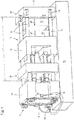
- Figure 1 shows a perspective side view of a mold clamping unit for a plastic injection molding machine, which can be used for processing plastics and other plasticizable masses such as powdery or ceramic masses.
- the mold clamping unit which has a stationary mold carrier 10 and a movable mold carrier 11, is arranged on the machine base 12.
- the height of the shape as a whole is the dimension that results from the sum of the dimensions a 1 and a 2 .
- this sum corresponds to the minimum distance between the mold carriers in the closing direction ss.
- the movable mold carrier 11 is actuated via a closing device 20, which in the exemplary embodiment is formed by a toggle lever mechanism, but in principle any other drive unit can also be used.
- a closing device 20 electromechanical drives or linear drives or other drive means can also be provided.
- guide elements 17 are provided as guide bars which are mounted on the stationary mold carrier. Such guide bars are sometimes also referred to as pillars. In the exemplary embodiment, they serve to guide the movable mold carrier 11 as well as the support element 21 during their movement, which is yet to be described. In principle, however, the mold height adjustment described below can also be used on a tie-bar-less injection molding machine, in which the stationary mold carrier 10 and movable mold carrier 11 via a force-transmitting element guided around the mold clamping space R, e.g. one or more brackets, are connected to one another.
- a force-transmitting element guided around the mold clamping space R e.g. one or more brackets
- the adjustable support element 21 carries in the direction of the movable mold carrier 11 the closing device 20 with which the movable mold carrier is actuated.
- a mold height adjustment 14 for adjusting the distance x between the stationary mold carrier 10 and the adjustable support element 21 while moving the support element.
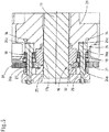
- the mold height adjustment 14 is via an in Fig. 2 drive 15 shown operable. From this drive are in Fig. 2 only to see the drive wheels with which a drive gear 31, which is central to the closing direction, is driven on the outside. With its outer teeth, this drive gear 31 is also in operative connection with output gears 32, which will be discussed in greater detail below.
- a locking device 16 is provided for releasably locking the support element 21 in its respective position under pretension of locking elements, which in the embodiment by the nuts 22, 23 in the Figures 3 to 5 are formed.
- the locking elements can be relieved by active actuation elements 26, in the exemplary embodiment by lifting elements to be explained in more detail, while the pretensioning of the locking elements to release the mold height adjustment 14 is released.
- the active actuation allows the mold height adjustment 14 to be actuated at any time.
- the locking device 16 can also be released during the movement of the movable mold carrier 11 in the closing direction ss towards the stationary mold carrier 10 and away from it, with the preload being released.
- the mold height adjustment 14 can also be actuated during the movement of the movable mold carrier 11 to adjust the distance x.
- the mold height adjustment 14 is shown in the exemplary embodiment on a column-guided three-platen clamping unit, i.e.
- a support element 21 for the closing device 20 is provided in addition to the stationary mold carrier 10 and the movable mold carrier 11, a support element 21 for the closing device 20 is provided.
- the device can also be used in other locking concepts such as e.g. Two-platen clamping units or tie-bar-less clamping units can be used.
- the mold height adjustment is then usually assigned to one of the mold carriers, in particular the stationary mold carrier 10.
- the mold clamping space R is usually free of force transmission elements between the mold carriers, since bracket-like elements are instead guided around the mold clamping space R as force transmission elements.
- Injection molds 13 of variable height a measured in the closing direction s-s, can be accommodated in the mold clamping space, so that the mold height may also have to be adapted via the mold height adjustment 14.
- the mold height adjustment 14 is arranged on an adjustment plate designed as a support element 21, i. the support element is adjustable in the closing direction s-s and therefore movable.
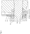
- the locking elements are formed by nuts 22, 23 which are in engagement with threaded sections 17a on the guide elements 17, ie on the bars or pillars, for the support element 21 and are adjustable by means of the drive 15.
- the actuating element 26 is at the same time at least one connecting means by which the nuts 22, 23 are brought into operative connection.
- the at least two nuts 22, 23 are as a result of the action of elastic means 18, which in the exemplary embodiment according to Fig. 5 are formed by disk spring assemblies, countered, ie pretensioned during operation. In the pre-tensioned position there is a minimal gap between the nuts 22 and 23, ie the nuts are pressed against the thread of the threaded sections 17a and thus fixed in the respective position.
- each guide element 17 has such an output gear 32, which according to the Figures 4 and 5 attached to the nut 22 by fasteners or is integral therewith.
- the output gears 32 are according to Fig. 2 Driven by a central drive gear 31.
- the drive gear 31 is gravity-compensated by a vertical support Gearbox network stored.
- the drive gear 31 itself is driven via the drive 15, this drive preferably being position-controlled and being servo-electric or hydraulic.
- the second nut 23 acts on the same thread and counteracts nut 22 against nut 23 by means of elastic means 18.
- the execution of the counter-locking makes it possible to carry out the tolerance pairing for the thread on the threaded section 17a in a wear-reducing manner or to allow larger tolerances in the dimensioning.
- the actuating element 26 is designed as a hydraulic piston-cylinder unit. It can also be implemented as a pneumatic or electromechanical element.
- the actuating element 26 according to Fig. 5 a piston rod 26a for a piston 26b mounted on the support element 21 and operable against the force of the elastic means 18. By supplying hydraulic medium into the cylinder space 26c, which is arranged on the support element 21, the piston 26b can in Fig. 5 moved to the left.
- the pretensioning force of the elastic means 18 is preferably greater than the forces occurring when the injection mold 13 is opened and closed, so that the support element 21 can be reliably locked in its respective position.
- the force of the actuating elements 26 is greater than the pretensioning force of the elastic means 18 in order to be able to remove this pretensioning if necessary. If this is taken into account, a backlash-free operating state can be achieved without adjustment. As soon as the process requires modifications to the mold height, the preload in the defined area can be released by means of the actuating element 26 (piston), which is the technical basis for creates a low-wear adjustment.
- the pre-tensioning force is chosen to be equal to or less than the operating force, an unsightly clacking effect can occur, as different thread flanks are loaded during the load change, which increases wear. If the preload is selected too high and is either not at all or not completely "relieved" for the adjustment process, an adjustment process is subject to wear and tear, in which the system is destroyed after a short time.
- the actuating element 26 is formed by two piston rods 26a of the piston-cylinder unit arranged diametrically to the central axis of the guide elements 17 in order to relieve the elastic means 18.
- only one actuating element with a counter bearing can be provided or it is also conceivable to provide more than two actuating elements if this is necessary for the symmetry of forces.
- the lifting movement can be monitored via the sensors 27, which are preferably used, to determine whether the respective end positions of the lifting movement have occurred. This monitoring should preferably be provided on every actuating element in order to avoid damage to the thread.
- a fine adjustment of the force distribution on the individual guide elements takes place on the opposite side of the guide elements 17 in a manner not shown in the drawing.
- a manually adjustable hollow nut acts as an adjustment element on this counter bearing. The aim of this setting option is to set the parallelism of the stationary mold carrier 10 and the movable mold carrier 11 to one another and to achieve a symmetrical distribution of forces in the guide elements.
- the lubrication of the individual contact points on the threads and gears takes place via a multi-stage lubrication concept.
- the spar thread is lubricated via a stationary access to the counter bearing plate to be adjusted.
- a lubricant reserve is filled directly in both nuts via this access.
- An optimal distribution of the lubricating medium at the thread contact points 22, 23 is ensured via connecting channels 22a, 23a and circumferential grooves 22b, 23b.
- the drive gear 31 is wetted with the lubricating medium at the lowest point in the tooth engagement area via sump lubrication in a lubricant sump 33.
- the lubricant is transferred to the contact points between the drive gear 31 and the output gear 32.
- Each lubrication point is supplied with its own supply line 30, which emanates from a central lubrication point 29 and lubricant distributors 34, which according to FIG Fig. 1 is laid out in a central position that is easily accessible for the operator.
- an adjustable support element is provided for a closing device 20 for moving the movable mold carrier 10 toward and away from the stationary mold carrier 11.
- a mold height adjustment 14 which can be driven by a drive 15 is used to adjust the mold height.
- a locking device releasably locks the support element 21 in its respective position under pretensioning of locking elements, that is to say the nuts 22, 23.
- the pretensioning is first released by actively relieving the locking elements. As a result, the locking elements are released from their respective positions and the mold height adjustment 14 is released at the same time.
- the support element 21 can be moved out of its respective position by actuating it, which leads to a change in the distance x between the stationary mold carrier 10 and the support element 21. If the changed position is reached, the mold height adjustment 14 can be fixed again by locking the locking device 16 while applying the pretension.
- the locking device can preferably also be unlocked during the movement of the movable mold carrier 11 in the closing direction ss and / or the mold height adjustment 14 can be actuated during the movement of the movable mold carrier 11 to adjust the distance x will. This allows an active closing force regulation.
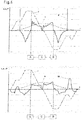
- the dynamic operating force on the support element 21 can be measured by means of a sensor 19 ( Fig. 1 ) like a handlebar sensor.
- the aim is to identify an area within the opening and closing movement of the movable mold carrier 11 via the total force characteristic curve in which the total force as a dynamic operating force without preload is always in the positive area, ie greater than or equal to zero.
- Fig. 6 shows a diagram which shows the dynamic operating forces. The operating force without pre-tensioning force is determined for this purpose. From a technical point of view, the total force on the adjustment plate must be "zero", since otherwise there would be a movement on the component in the sense of action equal to reaction.
- the area greater than or equal to zero is identified by the two points A, B.
- the loads in the guide element 17 are circumscribed with the total force.
- An actuation of the mold height adjustment 14 should be in take place in an area that lasts approximately from the start of the braking process in the rear end position of the movable mold carrier 11 and at most until the end of the acceleration phase from the rear end position. During this time, there is consistently a positive total force in the guide element 17 and the adjustment of the mold height a can take place without a load change in the movement thread.
Landscapes
- Engineering & Computer Science (AREA)
- Manufacturing & Machinery (AREA)
- Mechanical Engineering (AREA)
- Moulds For Moulding Plastics Or The Like (AREA)
- Injection Moulding Of Plastics Or The Like (AREA)
Claims (14)
- Unité de fermeture de moule ayant un dispositif d'adaptation automatique à la hauteur de moules de moulage par injection (13) à hauteur variable (a) mesurée dans la direction de fermeture du moule (s-s), pour une machine de moulage par injection pour l'élaboration de matières plastiques et d'autres matériaux plastifiables, comportant- un support de moule stationnaire (10),- un support de moule mobile (11),- un dispositif de fermeture pour le déplacement du support de moule mobile (11) dans la direction de fermeture (s-s) sur le support de moule stationnaire (10), vers celui-ci et en s'en éloignant,- un élément d'appui réglable (21) pour le dispositif de fermeture,- un réglage de la hauteur de moule (14) pour le réglage de la distance (x) entre le support de moule stationnaire (10) et l'élément d'appui réglable (21) par déplacement de l'élément d'appui,- une commande (15) pour l'actionnement du réglage de hauteur de moule (14),- un dispositif de verrouillage (16) pour un verrouillage amovible de l'élément d'appui (21) dans sa position courante par précontrainte des éléments de verrouillage, le dispositif de verrouillage étant amovible par suppression de la précontrainte, pendant le déplacement du support de moule mobile (11) dans la direction de fermeture (s-s) sur le support de moule stationnaire (10), vers celui-ci et en s'en éloignant, les éléments de verrouillage étant au choix libérés ou précontraints par des éléments d'actionnement actifs (26) pour libérer le réglage de la hauteur de moule (14),
caractérisée en ce que, lors du fonctionnement de la machine de moulage par injection, des moyens sont prévus pour la surveillance d'une force globale agissant sur l'élément d'appui (21) en tant que force motrice dynamique sans précontrainte et en ce que les éléments de verrouillage du dispositif de verrouillage sont amovibles pour supprimer la précontrainte pendant un intervalle de temps où la force globale mesurée est supérieure ou égale à zéro. - Unité de fermeture de moule selon la revendication 1, caractérisée en ce que les éléments de verrouillage peuvent être libérés, lors du fonctionnement de l'unité de fermeture de moule, de manière dynamique si nécessaire grâce à des éléments d'actionnement (26) actionnables de manière active.
- Unité de fermeture de moule selon la revendication 1 ou 2, caractérisée en ce que le réglage de hauteur de moule (14) pendant le déplacement du support de moule mobile (11) peut être actionné pour le réglage de la distance (x).
- Unité de fermeture de moule selon l'une des revendications précédentes, caractérisée en ce que le réglage de hauteur de moule (14) comprend en tant qu'éléments de verrouillage des écrous (22, 23), lesquels viennent en prise avec les sections filetées (17a) sur des éléments de guidage (17) pour l'élément d'appui (21) et sont réglables au moyen de la commande (15).
- Unité de fermeture de moule selon l'une des revendications précédentes, caractérisée en ce que le réglage de la hauteur de moule (14) comprend des écrous (22, 23) en tant qu'éléments de verrouillage et en ce que l'élément d'actionnement (26) est en même temps au moins un moyen de liaison grâce auquel les écrous coopèrent les uns avec les autres.
- Unité de fermeture de moule selon la revendication 4 ou 5, caractérisée en ce qu'au moins deux écrous (22, 23) peuvent être contrés suite à l'action de moyens élastiques (18) du dispositif de verrouillage (16).
- Unité de verrouillage de moule selon la revendication 5 ou 6, caractérisée en ce que les écrous (22, 23) sont adjacents à un plateau de fixation (25) et à l'élément d'appui (21), lesquels coopèrent l'un avec l'autre grâce au moyen de liaison.
- Unité de fermeture de moule selon l'une des revendications 4 à 7, caractérisée en ce que les écrous (22, 23) comportent des canaux de liaison (22a, 23a) et/ou des rainures (22b, 23b), lesquel(le)s sont en liaison avec un réservoir de lubrifiant pour la fourniture de lubrifiant aux sections filetées (17a).
- Unité de fermeture de moule selon l'une des revendications précédentes, caractérisée en ce que l'élément d'actionnement (26) est formé d'une tige de piston (26a) pour un piston (26b) d'une unité de cylindre à piston, fixé sur l'élément d'appui (21) et actionnable contre la force des moyens élastiques (18).
- Unité de fermeture de moule selon la revendication 9, caractérisée en ce que la chambre de cylindre (26c) de l'unité de cylindre à piston est disposée dans l'élément d'appui et en ce que la tige de piston (26a) fixée au plateau de fixation (25) intervient également avec des moyens élastiques (10) fixés sur l'élément d'appui.
- Unité de fermeture de moule selon l'une des revendications précédentes, caractérisée en ce que la force de précontrainte des moyens élastiques (18) est supérieure aux forces dynamiques enjeu lors de l'ouverture et de la fermeture du moule pour moulage par injection et en ce que la force des éléments d'actionnement (26) est supérieure à la force de précontrainte des moyens élastiques (18).
- Procédé pour l'adaptation automatique de la hauteur de moules de moulage par injection à hauteur variable (a) mesurée dans la direction de fermeture (s-s) sur une machine de moulage par injection pour l'élaboration de matières plastiques et d'autres matériaux plastifiables, comportant :- un support de moule stationnaire (10),- un support de moule mobile (11),- un élément d'appui réglable (21) pour un dispositif de fermeture (20) pour le déplacement du support de moule mobile (11) sur le support de moule stationnaire (10), vers celui-ci et en s'en éloignant,- une commande (15) pour le réglage de la hauteur de moule (14),- un dispositif de verrouillage (16) pour un verrouillage amovible de l'élément d'appui (21) dans sa position courante par précontrainte d'éléments de verrouillage,dans lequel le procédé comprend les étapes suivantes :- suppression de la précontrainte par libération active des éléments de verrouillage et libération des éléments de verrouillage de leur position courante pendant le déplacement du support de moule mobile (11) dans la direction de fermeture (s-s) sur le support de moule stationnaire (10) vers celui-ci et en s'éloignant de celui-ci lors du fonctionnement de la machine de moulage par injection,- libération du réglage de la hauteur de moule (14),- modification de la distance (x) entre le support de moule stationnaire (10) et l'élément d'appui (21) par déplacement de l'élément d'appui (21) au moyen de la commande (15),- définition du réglage de hauteur de moule (14) par verrouillage du dispositif de verrouillage (16) en appliquant la précontrainte,
caractérisé en ce que, lors du fonctionnement de la machine de moulage par injection, une force globale agissant sur l'élément d'appui (21) en tant que force motrice dynamique sans précontrainte est surveillée et en ce qu'une suppression de la précontrainte des éléments de verrouillage se produit pendant un intervalle de temps où la force globale mesurée est supérieure ou égale à zéro. - Procédé selon la revendication 12, caractérisé en ce que le réglage de la hauteur de moule (14) est actionné pour le réglage de la distance (x) pendant le déplacement du support de moule mobile (11).
- Procédé selon la revendication 12 ou 13, caractérisé en ce que la force globale agit soit en tant que mesure de force directe au moyen d'un détecteur (19) dans l'élément de guidage (17) ou en tant que grandeur de guidage indirecte, dérivée de la courbe de couple moteur du moteur d'entraînement de l'unité de fermeture de moule.
Applications Claiming Priority (2)
| Application Number | Priority Date | Filing Date | Title |
|---|---|---|---|
| DE102016119840.4A DE102016119840A1 (de) | 2016-10-18 | 2016-10-18 | Formschließeinheit mit einer Formhöhenverstellung sowie Verfahren zu deren Betätigung |
| PCT/EP2017/076363 WO2018073179A1 (fr) | 2016-10-18 | 2017-10-16 | Unité de fermeture d'un moule à réglage en hauteur du moule, et procédé permettant de l'actionner |
Publications (2)
| Publication Number | Publication Date |
|---|---|
| EP3529029A1 EP3529029A1 (fr) | 2019-08-28 |
| EP3529029B1 true EP3529029B1 (fr) | 2020-11-25 |
Family
ID=60191354
Family Applications (1)
| Application Number | Title | Priority Date | Filing Date |
|---|---|---|---|
| EP17791623.6A Active EP3529029B1 (fr) | 2016-10-18 | 2017-10-16 | Unité de fermeture d'un moule à réglage en hauteur du moule, et procédé permettant de l'actionner |
Country Status (7)
| Country | Link |
|---|---|
| US (1) | US10946571B2 (fr) |
| EP (1) | EP3529029B1 (fr) |
| JP (1) | JP7000425B2 (fr) |
| CN (1) | CN109843539B (fr) |
| CA (1) | CA3033702A1 (fr) |
| DE (1) | DE102016119840A1 (fr) |
| WO (1) | WO2018073179A1 (fr) |
Families Citing this family (4)
| Publication number | Priority date | Publication date | Assignee | Title |
|---|---|---|---|---|
| CN110962314B (zh) * | 2019-11-15 | 2022-05-17 | 海天塑机集团有限公司 | 一种减小注塑机在合模时拉杆的应力幅的方法 |
| DE102020117168A1 (de) * | 2020-06-30 | 2021-12-30 | Arburg Gmbh + Co Kg | Formschließeinheit für eine Spritzgießmaschine zur Verarbeitung von Kunststoffen |
| AT525188A1 (de) * | 2021-07-02 | 2023-01-15 | Engel Austria Gmbh | Schließeinheit für eine Formgebungsmaschine |
| CN121062155B (zh) * | 2025-11-06 | 2026-02-24 | 宁波爱思信息技术有限公司 | 一种拉杆预压式压合机构及其预紧力施加方法 |
Family Cites Families (20)
| Publication number | Priority date | Publication date | Assignee | Title |
|---|---|---|---|---|
| US3890081A (en) * | 1971-08-02 | 1975-06-17 | Litton Industrial Products | Injection holding machine clamp mechanism |
| DE2812301A1 (de) * | 1977-05-10 | 1978-11-23 | Plast Elastverarbeitungsmasch | Werkzeugschliess- und verriegelungseinheit, insbesondere fuer spritzgiessmaschinen |
| US4281977A (en) | 1979-10-01 | 1981-08-04 | Package Machinery Company | Apparatus for setting a clamping load |
| US4645443A (en) * | 1984-12-29 | 1987-02-24 | Kabushiki Kaisha Aoki Seisakusho | Mold-thickness adjusting apparatus in mold clamping mechanism |
| US4716952A (en) * | 1986-06-12 | 1988-01-05 | Prince Corporation | Means for squaring tie bars for die casting machines |
| JPH01221217A (ja) * | 1988-03-01 | 1989-09-04 | Niigata Eng Co Ltd | トグル式型締装置の型厚調整装置 |
| JPH0711944Y2 (ja) * | 1989-06-09 | 1995-03-22 | 宇部興産株式会社 | 成形機の型締装置 |
| US5972276A (en) * | 1996-10-04 | 1999-10-26 | Asahi Kasei Kogyo Kabushiki Kaisha | Method for the injection molding of a resin |
| JP3240275B2 (ja) * | 1997-09-08 | 2001-12-17 | 東芝機械株式会社 | 射出成形機の型締装置 |
| US6719553B1 (en) * | 1998-03-24 | 2004-04-13 | Karl Hehl | Mold-closing unit for an injection molding machine |
| DE19812741B4 (de) | 1998-03-24 | 2005-04-28 | Karl Hehl | Formschließeinheit für eine Spritzgießmaschine |
| DE19945287A1 (de) * | 1998-03-24 | 2001-03-29 | Karl Hehl | Formschliesseinheit für eine Spritzgiessmaschine |
| DE19819055C1 (de) * | 1998-04-29 | 1999-07-08 | Karl Hehl | Schwenkvorrichtung für die Spritzgießeinheit einer Spritzgießmaschine |
| AT5823U1 (de) * | 2001-10-29 | 2002-12-27 | Engel Gmbh Maschbau | Einrichtung zum spritzgiessen von kunststoff |
| DE10210869C1 (de) | 2002-03-12 | 2003-07-17 | Karl Hehl | Formschliesseinheit mit einer Formhöhenverstellung sowie Verfahren zu deren Betätigung |
| JP3792663B2 (ja) * | 2003-03-12 | 2006-07-05 | ファナック株式会社 | 成形機の型締機構 |
| DE102004032521A1 (de) * | 2004-07-06 | 2006-02-16 | Demag Ergotech Gmbh | Formschließeinheit |
| DE102004050311B4 (de) * | 2004-10-15 | 2008-02-07 | Krauss Maffei Gmbh | Schließeinheit für ein Spritzgießmaschine mit Etagenwerkzeug |
| BR112012025004A2 (pt) * | 2010-04-01 | 2021-05-04 | Athena Automation Ltd. | máquina de moldagem de injeção, combinação de uma máquina de moldagem de injeção e um aparelho robô de entrada lateral para interagir com a máquina, e método de manipular artigos moldados produzidos por uma máquina de moldagem de injeção |
| JP6068387B2 (ja) * | 2014-04-10 | 2017-01-25 | ファナック株式会社 | 昇降式信号灯を備えた射出成形機 |
-
2016
- 2016-10-18 DE DE102016119840.4A patent/DE102016119840A1/de not_active Withdrawn
-
2017
- 2017-10-16 WO PCT/EP2017/076363 patent/WO2018073179A1/fr not_active Ceased
- 2017-10-16 CN CN201780064283.8A patent/CN109843539B/zh active Active
- 2017-10-16 JP JP2019520779A patent/JP7000425B2/ja active Active
- 2017-10-16 US US16/343,063 patent/US10946571B2/en active Active
- 2017-10-16 EP EP17791623.6A patent/EP3529029B1/fr active Active
- 2017-10-16 CA CA3033702A patent/CA3033702A1/fr active Pending
Non-Patent Citations (1)
| Title |
|---|
| None * |
Also Published As
| Publication number | Publication date |
|---|---|
| JP7000425B2 (ja) | 2022-01-19 |
| CN109843539A (zh) | 2019-06-04 |
| WO2018073179A1 (fr) | 2018-04-26 |
| DE102016119840A1 (de) | 2018-04-19 |
| JP2019532844A (ja) | 2019-11-14 |
| CN109843539B (zh) | 2021-06-15 |
| US10946571B2 (en) | 2021-03-16 |
| CA3033702A1 (fr) | 2018-04-26 |
| EP3529029A1 (fr) | 2019-08-28 |
| US20190263037A1 (en) | 2019-08-29 |
Similar Documents
| Publication | Publication Date | Title |
|---|---|---|
| EP2629954B1 (fr) | Dispositife d'injection avec presse à genouillère | |
| EP3529029B1 (fr) | Unité de fermeture d'un moule à réglage en hauteur du moule, et procédé permettant de l'actionner | |
| DE102020118161B4 (de) | Gusswerkzeug-Spannvorrichtung mit einer Halb-Buchse und Spritzgussvorrichtung | |
| DE102013017358B4 (de) | SPRITZGIEßMASCHINE MIT FUNKTION ZUM EINSTELLEN DES GLEICHGEWICHTS DER VERBINDUNGSSTANGEN | |
| EP3655225B1 (fr) | Unite de fermeture de moule pour machine de moulage par injection | |
| DE19932741C2 (de) | Verfahren und Vorrichtung zum Schließen und Öffnen des Werkzeugs einer Kunststoffverarbeitungsmaschine | |
| DE60126528T2 (de) | Produktauswurfvorrichtung und Verfahren für eine Spritzgiessanlage | |
| EP3710222B1 (fr) | Unité de fermeture de moule destinée à une machine de moulage par injection ainsi que procédé de blocage d'un élément de transmission de force | |
| DE68912756T2 (de) | Formschliessvorrichtung vom typ mit zwei platten. | |
| EP1068060B1 (fr) | Unite de fermeture de moule pour une presse d'injection | |
| EP0620095A2 (fr) | Machine à mouler par injection, notamment machine à mouler par injection des matières plastiques | |
| EP4458547A1 (fr) | Unité de fermeture de moule et procédé de fonctionnement d'une unité de fermeture de moule d'une machine de traitement de matières plastiques | |
| DE10210869C1 (de) | Formschliesseinheit mit einer Formhöhenverstellung sowie Verfahren zu deren Betätigung | |
| DE102008023720B3 (de) | Formschließeinheit einer Spritzgießmaschine | |
| EP2125326B1 (fr) | Procédé d'exploitation d'une presse d'injection dotée de deux mécanismes à genouillère, et presse d'injection associée | |
| DE4411650C2 (de) | Formschließeinheit für eine Spritzgießmaschine | |
| EP3311973B1 (fr) | Éjecteur multibroche doté du dispositif de protection contre les surcharges | |
| DE102006026608B4 (de) | Säulenziehvorrichtung | |
| DE102022116296A1 (de) | Schließeinheit für eine Formgebungsmaschine | |
| DE112023003340T5 (de) | Formspannvorrichtung, spritzgiessmaschine,und formspannverfahren | |
| DE19848391A1 (de) | Gummispritzpresse | |
| DE19945287A1 (de) | Formschliesseinheit für eine Spritzgiessmaschine | |
| WO2014013003A1 (fr) | Unité de fermeture pour une machine de moulage par injection de matière plastique | |
| EP1086798A1 (fr) | Unité de fermeture de moule pour une presse d'injection | |
| DE102017007911A1 (de) | Formwerkzeug-Schließvorrichtung einer Spritzgießmaschine |
Legal Events
| Date | Code | Title | Description |
|---|---|---|---|
| STAA | Information on the status of an ep patent application or granted ep patent |
Free format text: STATUS: UNKNOWN |
|
| STAA | Information on the status of an ep patent application or granted ep patent |
Free format text: STATUS: THE INTERNATIONAL PUBLICATION HAS BEEN MADE |
|
| PUAI | Public reference made under article 153(3) epc to a published international application that has entered the european phase |
Free format text: ORIGINAL CODE: 0009012 |
|
| STAA | Information on the status of an ep patent application or granted ep patent |
Free format text: STATUS: REQUEST FOR EXAMINATION WAS MADE |
|
| 17P | Request for examination filed |
Effective date: 20190510 |
|
| AK | Designated contracting states |
Kind code of ref document: A1 Designated state(s): AL AT BE BG CH CY CZ DE DK EE ES FI FR GB GR HR HU IE IS IT LI LT LU LV MC MK MT NL NO PL PT RO RS SE SI SK SM TR |
|
| AX | Request for extension of the european patent |
Extension state: BA ME |
|
| DAV | Request for validation of the european patent (deleted) | ||
| DAX | Request for extension of the european patent (deleted) | ||
| GRAP | Despatch of communication of intention to grant a patent |
Free format text: ORIGINAL CODE: EPIDOSNIGR1 |
|
| STAA | Information on the status of an ep patent application or granted ep patent |
Free format text: STATUS: GRANT OF PATENT IS INTENDED |
|
| INTG | Intention to grant announced |
Effective date: 20200615 |
|
| GRAS | Grant fee paid |
Free format text: ORIGINAL CODE: EPIDOSNIGR3 |
|
| GRAA | (expected) grant |
Free format text: ORIGINAL CODE: 0009210 |
|
| STAA | Information on the status of an ep patent application or granted ep patent |
Free format text: STATUS: THE PATENT HAS BEEN GRANTED |
|
| AK | Designated contracting states |
Kind code of ref document: B1 Designated state(s): AL AT BE BG CH CY CZ DE DK EE ES FI FR GB GR HR HU IE IS IT LI LT LU LV MC MK MT NL NO PL PT RO RS SE SI SK SM TR |
|
| REG | Reference to a national code |
Ref country code: GB Ref legal event code: FG4D Free format text: NOT ENGLISH |
|
| REG | Reference to a national code |
Ref country code: CH Ref legal event code: EP |
|
| REG | Reference to a national code |
Ref country code: AT Ref legal event code: REF Ref document number: 1337776 Country of ref document: AT Kind code of ref document: T Effective date: 20201215 |
|
| REG | Reference to a national code |
Ref country code: DE Ref legal event code: R096 Ref document number: 502017008398 Country of ref document: DE |
|
| REG | Reference to a national code |
Ref country code: IE Ref legal event code: FG4D Free format text: LANGUAGE OF EP DOCUMENT: GERMAN |
|
| REG | Reference to a national code |
Ref country code: CH Ref legal event code: NV Representative=s name: MERVELIX SARL, CH |
|
| REG | Reference to a national code |
Ref country code: NL Ref legal event code: FP |
|
| PG25 | Lapsed in a contracting state [announced via postgrant information from national office to epo] |
Ref country code: NO Free format text: LAPSE BECAUSE OF FAILURE TO SUBMIT A TRANSLATION OF THE DESCRIPTION OR TO PAY THE FEE WITHIN THE PRESCRIBED TIME-LIMIT Effective date: 20210225 Ref country code: GR Free format text: LAPSE BECAUSE OF FAILURE TO SUBMIT A TRANSLATION OF THE DESCRIPTION OR TO PAY THE FEE WITHIN THE PRESCRIBED TIME-LIMIT Effective date: 20210226 Ref country code: FI Free format text: LAPSE BECAUSE OF FAILURE TO SUBMIT A TRANSLATION OF THE DESCRIPTION OR TO PAY THE FEE WITHIN THE PRESCRIBED TIME-LIMIT Effective date: 20201125 Ref country code: RS Free format text: LAPSE BECAUSE OF FAILURE TO SUBMIT A TRANSLATION OF THE DESCRIPTION OR TO PAY THE FEE WITHIN THE PRESCRIBED TIME-LIMIT Effective date: 20201125 Ref country code: PT Free format text: LAPSE BECAUSE OF FAILURE TO SUBMIT A TRANSLATION OF THE DESCRIPTION OR TO PAY THE FEE WITHIN THE PRESCRIBED TIME-LIMIT Effective date: 20210325 |
|
| PG25 | Lapsed in a contracting state [announced via postgrant information from national office to epo] |
Ref country code: BG Free format text: LAPSE BECAUSE OF FAILURE TO SUBMIT A TRANSLATION OF THE DESCRIPTION OR TO PAY THE FEE WITHIN THE PRESCRIBED TIME-LIMIT Effective date: 20210225 Ref country code: PL Free format text: LAPSE BECAUSE OF FAILURE TO SUBMIT A TRANSLATION OF THE DESCRIPTION OR TO PAY THE FEE WITHIN THE PRESCRIBED TIME-LIMIT Effective date: 20201125 Ref country code: IS Free format text: LAPSE BECAUSE OF FAILURE TO SUBMIT A TRANSLATION OF THE DESCRIPTION OR TO PAY THE FEE WITHIN THE PRESCRIBED TIME-LIMIT Effective date: 20210325 Ref country code: LV Free format text: LAPSE BECAUSE OF FAILURE TO SUBMIT A TRANSLATION OF THE DESCRIPTION OR TO PAY THE FEE WITHIN THE PRESCRIBED TIME-LIMIT Effective date: 20201125 Ref country code: SE Free format text: LAPSE BECAUSE OF FAILURE TO SUBMIT A TRANSLATION OF THE DESCRIPTION OR TO PAY THE FEE WITHIN THE PRESCRIBED TIME-LIMIT Effective date: 20201125 |
|
| REG | Reference to a national code |
Ref country code: LT Ref legal event code: MG9D |
|
| PG25 | Lapsed in a contracting state [announced via postgrant information from national office to epo] |
Ref country code: HR Free format text: LAPSE BECAUSE OF FAILURE TO SUBMIT A TRANSLATION OF THE DESCRIPTION OR TO PAY THE FEE WITHIN THE PRESCRIBED TIME-LIMIT Effective date: 20201125 |
|
| PG25 | Lapsed in a contracting state [announced via postgrant information from national office to epo] |
Ref country code: LT Free format text: LAPSE BECAUSE OF FAILURE TO SUBMIT A TRANSLATION OF THE DESCRIPTION OR TO PAY THE FEE WITHIN THE PRESCRIBED TIME-LIMIT Effective date: 20201125 Ref country code: CZ Free format text: LAPSE BECAUSE OF FAILURE TO SUBMIT A TRANSLATION OF THE DESCRIPTION OR TO PAY THE FEE WITHIN THE PRESCRIBED TIME-LIMIT Effective date: 20201125 Ref country code: EE Free format text: LAPSE BECAUSE OF FAILURE TO SUBMIT A TRANSLATION OF THE DESCRIPTION OR TO PAY THE FEE WITHIN THE PRESCRIBED TIME-LIMIT Effective date: 20201125 Ref country code: SM Free format text: LAPSE BECAUSE OF FAILURE TO SUBMIT A TRANSLATION OF THE DESCRIPTION OR TO PAY THE FEE WITHIN THE PRESCRIBED TIME-LIMIT Effective date: 20201125 Ref country code: RO Free format text: LAPSE BECAUSE OF FAILURE TO SUBMIT A TRANSLATION OF THE DESCRIPTION OR TO PAY THE FEE WITHIN THE PRESCRIBED TIME-LIMIT Effective date: 20201125 Ref country code: SK Free format text: LAPSE BECAUSE OF FAILURE TO SUBMIT A TRANSLATION OF THE DESCRIPTION OR TO PAY THE FEE WITHIN THE PRESCRIBED TIME-LIMIT Effective date: 20201125 |
|
| REG | Reference to a national code |
Ref country code: DE Ref legal event code: R097 Ref document number: 502017008398 Country of ref document: DE |
|
| PG25 | Lapsed in a contracting state [announced via postgrant information from national office to epo] |
Ref country code: DK Free format text: LAPSE BECAUSE OF FAILURE TO SUBMIT A TRANSLATION OF THE DESCRIPTION OR TO PAY THE FEE WITHIN THE PRESCRIBED TIME-LIMIT Effective date: 20201125 |
|
| PLBE | No opposition filed within time limit |
Free format text: ORIGINAL CODE: 0009261 |
|
| STAA | Information on the status of an ep patent application or granted ep patent |
Free format text: STATUS: NO OPPOSITION FILED WITHIN TIME LIMIT |
|
| PG25 | Lapsed in a contracting state [announced via postgrant information from national office to epo] |
Ref country code: AL Free format text: LAPSE BECAUSE OF FAILURE TO SUBMIT A TRANSLATION OF THE DESCRIPTION OR TO PAY THE FEE WITHIN THE PRESCRIBED TIME-LIMIT Effective date: 20201125 |
|
| 26N | No opposition filed |
Effective date: 20210826 |
|
| PG25 | Lapsed in a contracting state [announced via postgrant information from national office to epo] |
Ref country code: SI Free format text: LAPSE BECAUSE OF FAILURE TO SUBMIT A TRANSLATION OF THE DESCRIPTION OR TO PAY THE FEE WITHIN THE PRESCRIBED TIME-LIMIT Effective date: 20201125 |
|
| PG25 | Lapsed in a contracting state [announced via postgrant information from national office to epo] |
Ref country code: ES Free format text: LAPSE BECAUSE OF FAILURE TO SUBMIT A TRANSLATION OF THE DESCRIPTION OR TO PAY THE FEE WITHIN THE PRESCRIBED TIME-LIMIT Effective date: 20201125 |
|
| PG25 | Lapsed in a contracting state [announced via postgrant information from national office to epo] |
Ref country code: IS Free format text: LAPSE BECAUSE OF FAILURE TO SUBMIT A TRANSLATION OF THE DESCRIPTION OR TO PAY THE FEE WITHIN THE PRESCRIBED TIME-LIMIT Effective date: 20210325 |
|
| REG | Reference to a national code |
Ref country code: BE Ref legal event code: MM Effective date: 20211031 |
|
| PG25 | Lapsed in a contracting state [announced via postgrant information from national office to epo] |
Ref country code: MC Free format text: LAPSE BECAUSE OF FAILURE TO SUBMIT A TRANSLATION OF THE DESCRIPTION OR TO PAY THE FEE WITHIN THE PRESCRIBED TIME-LIMIT Effective date: 20201125 |
|
| PG25 | Lapsed in a contracting state [announced via postgrant information from national office to epo] |
Ref country code: LU Free format text: LAPSE BECAUSE OF NON-PAYMENT OF DUE FEES Effective date: 20211016 Ref country code: BE Free format text: LAPSE BECAUSE OF NON-PAYMENT OF DUE FEES Effective date: 20211031 |
|
| PG25 | Lapsed in a contracting state [announced via postgrant information from national office to epo] |
Ref country code: IE Free format text: LAPSE BECAUSE OF NON-PAYMENT OF DUE FEES Effective date: 20211016 |
|
| P01 | Opt-out of the competence of the unified patent court (upc) registered |
Effective date: 20230518 |
|
| PG25 | Lapsed in a contracting state [announced via postgrant information from national office to epo] |
Ref country code: CY Free format text: LAPSE BECAUSE OF FAILURE TO SUBMIT A TRANSLATION OF THE DESCRIPTION OR TO PAY THE FEE WITHIN THE PRESCRIBED TIME-LIMIT Effective date: 20201125 |
|
| PG25 | Lapsed in a contracting state [announced via postgrant information from national office to epo] |
Ref country code: HU Free format text: LAPSE BECAUSE OF FAILURE TO SUBMIT A TRANSLATION OF THE DESCRIPTION OR TO PAY THE FEE WITHIN THE PRESCRIBED TIME-LIMIT; INVALID AB INITIO Effective date: 20171016 |
|
| PG25 | Lapsed in a contracting state [announced via postgrant information from national office to epo] |
Ref country code: MK Free format text: LAPSE BECAUSE OF FAILURE TO SUBMIT A TRANSLATION OF THE DESCRIPTION OR TO PAY THE FEE WITHIN THE PRESCRIBED TIME-LIMIT Effective date: 20201125 |
|
| PG25 | Lapsed in a contracting state [announced via postgrant information from national office to epo] |
Ref country code: TR Free format text: LAPSE BECAUSE OF FAILURE TO SUBMIT A TRANSLATION OF THE DESCRIPTION OR TO PAY THE FEE WITHIN THE PRESCRIBED TIME-LIMIT Effective date: 20201125 |
|
| PG25 | Lapsed in a contracting state [announced via postgrant information from national office to epo] |
Ref country code: MT Free format text: LAPSE BECAUSE OF FAILURE TO SUBMIT A TRANSLATION OF THE DESCRIPTION OR TO PAY THE FEE WITHIN THE PRESCRIBED TIME-LIMIT Effective date: 20201125 |
|
| REG | Reference to a national code |
Ref country code: CH Ref legal event code: U11 Free format text: ST27 STATUS EVENT CODE: U-0-0-U10-U11 (AS PROVIDED BY THE NATIONAL OFFICE) Effective date: 20251101 |
|
| PGFP | Annual fee paid to national office [announced via postgrant information from national office to epo] |
Ref country code: NL Payment date: 20251023 Year of fee payment: 9 |
|
| PGFP | Annual fee paid to national office [announced via postgrant information from national office to epo] |
Ref country code: DE Payment date: 20250911 Year of fee payment: 9 |
|
| PGFP | Annual fee paid to national office [announced via postgrant information from national office to epo] |
Ref country code: GB Payment date: 20251024 Year of fee payment: 9 |
|
| PGFP | Annual fee paid to national office [announced via postgrant information from national office to epo] |
Ref country code: AT Payment date: 20251021 Year of fee payment: 9 |
|
| PGFP | Annual fee paid to national office [announced via postgrant information from national office to epo] |
Ref country code: IT Payment date: 20251031 Year of fee payment: 9 |
|
| PGFP | Annual fee paid to national office [announced via postgrant information from national office to epo] |
Ref country code: FR Payment date: 20251024 Year of fee payment: 9 |
|
| PGFP | Annual fee paid to national office [announced via postgrant information from national office to epo] |
Ref country code: CH Payment date: 20251101 Year of fee payment: 9 |