EP3529582B1 - Appareil pour tester un arbre et/ou une piece mecanique montee sur l'arbre et utilisation d'un tel appareil - Google Patents
Appareil pour tester un arbre et/ou une piece mecanique montee sur l'arbre et utilisation d'un tel appareil Download PDFInfo
- Publication number
- EP3529582B1 EP3529582B1 EP17793894.1A EP17793894A EP3529582B1 EP 3529582 B1 EP3529582 B1 EP 3529582B1 EP 17793894 A EP17793894 A EP 17793894A EP 3529582 B1 EP3529582 B1 EP 3529582B1
- Authority
- EP
- European Patent Office
- Prior art keywords
- axis
- shaft
- cylinder
- connection
- rotation
- Prior art date
- Legal status (The legal status is an assumption and is not a legal conclusion. Google has not performed a legal analysis and makes no representation as to the accuracy of the status listed.)
- Active
Links
Images



Classifications
-
- G—PHYSICS
- G01—MEASURING; TESTING
- G01M—TESTING STATIC OR DYNAMIC BALANCE OF MACHINES OR STRUCTURES; TESTING OF STRUCTURES OR APPARATUS, NOT OTHERWISE PROVIDED FOR
- G01M13/00—Testing of machine parts
- G01M13/02—Gearings; Transmission mechanisms
- G01M13/027—Test-benches with force-applying means, e.g. loading of drive shafts along several directions
-
- G—PHYSICS
- G01—MEASURING; TESTING
- G01N—INVESTIGATING OR ANALYSING MATERIALS BY DETERMINING THEIR CHEMICAL OR PHYSICAL PROPERTIES
- G01N3/00—Investigating strength properties of solid materials by application of mechanical stress
- G01N3/20—Investigating strength properties of solid materials by application of mechanical stress by applying steady bending forces
Definitions
- the present invention relates to the field of apparatus for testing a shaft and / or a mechanical part mounted on the shaft, for example a wheel mounted on the shaft.
- railway vehicle bogies are provided with axles, each axle comprising two coaxial wheels carried by a shaft, each wheel being intended to run on a respective rail of a railway track.
- the body of the rail vehicle is supported on the shaft which is itself supported on the wheels.
- the shaft Due to the distances between, on the one hand, the points of support of the body on the shaft, and, on the other hand, the wheels, the shaft is highly stressed in bending. In addition, due to the rotation of the shaft when the bogie rolls along the track, the shaft undergoes repeated cycles of bending / deflection which ultimately causes fatigue of the shaft.
- EP 0 112 400 A1 , US 4,862,738 A , JP H04 52545 A and FR 2 365 117 A1 describe such test devices.
- One of the aims of the invention is to propose an apparatus for testing a shaft and / or a mechanism mounted on the shaft, which is simple to implement, reliable and which makes it possible to carry out tests representative of the real conditions of use. .
- the invention provides an apparatus for testing a shaft and / or a mechanical part mounted on the shaft according to claim 1
- the apparatus may include one or more of the optional features of claims 2 to 9.
- the invention also relates to the use of an apparatus as defined above according to claim 10.
- the use can be according to claim 11.
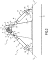
- the apparatus 2 represented on the Figures 1 and 2 is suitable for carrying out a bending test of a shaft, in particular an axle shaft, and in particular a bogie axle shaft of a railway vehicle.
- a shaft 4 to be tested is installed on the device 2 and ready to be tested in bending.
- the shaft 4 is shown at rest, ie not stressed in bending.
- the apparatus 2 comprises an immobilization device 6 for immobilizing a first portion 4A of the shaft 4, the shaft 4 at rest extending along a first axis A1, and a displacement device 8 for moving a second portion 4B of the shaft 4 perpendicular to the first axis A1, so as to bias the shaft 4 in bending.
- the first portion 4A of the shaft 4 and the second portion 4B of the shaft 4 are spaced from one another along the first axis A1 and the shaft 4.
- the shaft 4 is stressed in bending between the first portion 4A and the second portion 4B of the shaft 4.
- the first portion 4A and the second portion 4B of the shaft are here the two opposite end portions of the shaft 4.
- the displacement device 8 is configured to move the second portion 4B of the shaft 4 in a displacement plane P substantially perpendicular to the first axis A1.
- the first axis A1 is substantially horizontal and the displacement plane P is substantially vertical.
- the displacement device 8 comprises a first cylinder 10 extending along an axis of first cylinder T1 substantially perpendicular to the first axis A1, a second cylinder 10 extending along an axis of second cylinder T2 substantially perpendicular to the first axis A1, and a connecting device 14.
- the first cylinder 10 has two opposite connection ends 10A, 10B.
- the first cylinder 10 is capable of generating a rectilinear translation of a connection end 10A relative to the other 10B along the first cylinder axis T1.
- the second cylinder 12 has two opposite connection ends 12A, 12B.
- the second cylinder 12 is capable of generating a rectilinear translation of a connection end 14A relative to the other 14B along the second cylinder axis T2.
- the first cylinder 10 and the second cylinder 12 each preferably have two working directions.
- each of the first cylinder 10 and the second cylinder 12 is configured to selectively generate a tensile force or a compressive force along its cylinder axis T1, T2, to respectively bring the ends of the cylinder 10, 12 closer or apart from one another.
- the axis of the first cylinder T1 is orthogonal to the first axis A1.
- the axis of the second cylinder T2 is orthogonal to the first axis A1.
- the axis of first cylinder T1 and the axis of second cylinder T2 extend along the displacement plane P.
- the axis of first cylinder T1 and the axis of second cylinder T2 form a non-zero angle between them.
- the axis of the first cylinder T1 and the axis of the second cylinder T2 are substantially coplanar and extend in the plane of movement P.
- the connecting device 14 is configured to be disposed between, on the one hand, the first cylinder 10 and the second cylinder 12, and, on the other hand, the shaft 4, so that the first cylinder 10 and the second cylinder 12 can urge the shaft 4 perpendicular to the first axis A1.
- connection device 14 is configured to produce, between the shaft 4 and the end 10A of the first jack 10 linked to the shaft 4, a first connection 16 preventing relative translation perpendicular to the first axis A1 and allowing relative rotation around of the first axis A1.
- a ball joint allows three rotations around three axes orthogonal to each other intersecting in a center of rotation and prohibits any translation.
- An annular linear link allows three rotations and a single translation along a single translation axis, by prohibiting translations perpendicular to this translation axis, the center of rotation sliding along the axis of rotation.
- a pivot link allows rotation around a single axis of rotation and prohibits any translation.
- a sliding pivot link allows rotation about a single axis of rotation, and allows a single translation along the axis of rotation, by preventing translations perpendicular to the axis of rotation.
- the first link 16 is a ball joint whose center of rotation is located on the first axis, an annular linear link whose axis of translation is the first axis A1 and the center of rotation is located on the first axis A1, a pivot link whose axis of rotation is the first axis A1 or a sliding pivot link, whose axis of rotation and translation is the first axis A1.
- the connecting device 14 is configured to produce, between the shaft 4 and the end 12A of the second jack linked to the shaft 4 or between the end 10A of the first jack 10 linked to the shaft 4 by the first link 16 and the end 12A of the second jack 10 linked to the shaft 4, a second link 18 preventing relative translation perpendicular to the first axis A1 and allowing relative rotation about a second axis A2 parallel to the first axis A1.
- the second link 18 is a ball joint whose center of rotation is located on the second axis A2, a linear annular link whose translation axis is the second axis A2 and the center of rotation is located on the second axis A2, a pivot link whose axis of rotation is the second axis A2, or a sliding pivot link whose axis of rotation and translation is the second axis A2.
- connection device 14 is here configured to produce the second connection 18 between the end 10A of the first jack 10 linked to the shaft 4 by the first link 16 and the end 12A of the second jack 10 linked to the shaft 4
- second axis A2 is distinct from the first axis A1.
- the first link 16 is a ball joint whose center of rotation O is centered on the first axis A1.
- the connecting device 14 comprises a first end piece 20 rigidly fixed to the end 10A of the first jack 10, the first end piece 20 defining a ball joint housing receiving a ball joint 22 in rotation ( Figure 5 ).
- the ball joint 22 is provided with an orifice for receiving the second portion 4B of the shaft 4, for mounting the ball joint 22 on the shaft 4.
- the ball joint 22 is stationary in translation along the shaft 4.
- the first link 16 is an annular linear link.
- the ball joint 22 is mounted on the shaft 4 while being movable in translation along the first axis A1 relative to the shaft 4. This makes it possible to avoid the appearance of mechanical stresses during the stressing of the shaft 4 in flexion.
- the ball joint can be replaced by a spherical roller bearing disposed in the end piece, allowing rotation around a primary axis of rotation coinciding with the first axis A1 and allowing rotations of limited amplitude around two axis of rotation perpendicular to the primary axis of rotation.
- the second link 18 is a pivot link, the second axis A2 being distinct from the first axis A1.
- the connecting device 14 comprises a second end piece 24 rigidly fixed to the end 12A of the second cylinder 10, the second end piece 24 being pivotally mounted on the first end piece 20 around the second axis A2 by means of a pivot 28.
- L 'end piece 26 is for example a yoke end piece.
- the apparatus 2 comprises a fixed frame 30.
- the immobilization device 6 makes it possible to immobilize the first portion 4A of the shaft 4 relative to the frame.
- the first cylinder 10 and the second cylinder 12 are each arranged between the frame 30 and the connecting device 14 to move the second portion 4B of the shaft 4 relative to the frame 30 perpendicular to the first axis A1.
- the first jack 10 has its connection end 10A linked to the shaft 4 via the connection device 14, and its other connection end 10B linked to the frame 30 via a third connection 32 allowing rotation relative around a third axis A3 parallel to the first axis A1 and preventing any translation perpendicular to the third axis A3.
- the third axis A3 is stationary.
- the second jack 12 has its connection end 12A linked to the shaft 4 by means of the connection device 14, and its other end 12B linked to the frame 30 by means of a fourth connection 34 allowing relative rotation around of a fourth axis A4 parallel to the first axis A1 and prohibiting any translation perpendicular to the fourth axis A4.
- the fourth axis A4 is stationary.
- the first axis A1, the second axis A2, the third axis A3 and the fourth axis A4 are distinct and parallel to each other.
- the third link 32 and the fourth link 34 are ball joints whose centers are located respectively on the third axis A3 and on the fourth axis A4.
- the third link 32 is an annular linear link, the axis of translation of which is the third axis A3, or a pivot link or a sliding pivot link whose axis of rotation, and where appropriate of translation, is the third axis A3.
- the fourth connection 34 is an annular linear connection, the axis of translation of which is the fourth axis A4, or a pivot connection or a sliding pivot connection whose axis of rotation, and where appropriate of translation, is the fourth axis A4.
- the second portion 4B of the shaft 4 moves during the operation of the displacement device 8.
- the third axis A3 and the fourth axis A4 are stationary relative to the frame 30. Their positions are invariable during the operation of the displacement device 8.
- first cylinder T1 When the shaft 4 is at rest, the axis of first cylinder T1 intersects the first axis A1 and the third axis A3, and the axis of second cylinder T2 intersects the second axis A2 and the fourth axis A4.
- the first cylinder 10 and the second cylinder 12 converge towards each other in the direction of the first axis A1.
- the distance between the first axis A1 and the second axis A2 is strictly less than the distance between the third axis A3 and the fourth axis A4.
- connection ends 10A, 12A of the first cylinder 10 and of the second cylinder 12 linked to the connection device 14 are closer to each other than the ends of connection 10B, 12B opposite of the first cylinder 10 and the second cylinder 12 rotatably mounted around the third axis A3 and the fourth axis A4 respectively.
- the first cylinder 10 and the second cylinder 12 each comprise a cylinder body 36 and a cylinder rod 38 sliding relative to the cylinder body 36, respectively along the axis of the first cylinder T1 and the axis of the second cylinder T2.
- a connection end 10A, 12A of each of the first jack 10 and of the second jack 12 is the end of the jack rod 38 of this jack opposite to the jack body 36 of this jack, the other link end 10B, 12B of each of the first jack 10 and of the second jack 12 being the end of the jack body 36 of this jack opposite to the jack rod 38.
- the cylinder rod 38 of each of the first cylinder 10 and the second cylinder 12 is linked to the connecting device 14 and the cylinder body 36 of each of the first cylinder 10 and of the second cylinder 12 is rotatably mounted around a fixed axis A3 , A4.
- the configuration of the first cylinder 10 and / or the configuration of the second cylinder 12 is reversed.
- the first cylinder 10 and the second cylinder 12 are hydraulic cylinders.
- a hydraulic cylinder uses a pressurized liquid to move a piston inside the cylinder body, the cylinder rod being integral with the piston.
- first cylinder 10 and the second cylinder 12 are electric cylinders.
- An electric actuator uses for example a screw / nut assembly and an electric motor to drive the screw and the nut in rotation relative to each other and to move the actuator rod in translation relative to the actuator body.
- the immobilization device 6 comprises a support 40 and carrying a roller 42 hooped on a bearing of the shaft 4 intended to receive a wheel of a railway vehicle, the roller 42 being mounted fixed on the support 40.
- hovered it is meant that the roller 42 is fitted tightly onto the bearing surface of the shaft 4 intended to receive the wheel.
- the roller 42 is replaced by a wheel.
- the use of a roller 42 or a wheel mounted on the shaft makes it possible to reproduce the conditions of use of the shaft 4, in particular with the constraints generated at the shaft / wheel interface.
- the frame 30 is here in the form of a plate, also called “marble”.
- the support 40 has the form of an upright extending upwards from the frame 30 and carrying the roller 42 at its upper end.
- Other frames 30 and other immobilization devices 6 can be envisaged.
- the shaft 4 here has an external diameter too small to cooperate directly with the connecting device 14.
- the apparatus 2 comprises an adapter 44 for enlarging the diameter, the connection device 14 being mounted on the shaft 4 by means of the adapter 44.
- the adapter 44 has an orifice for receiving the shaft 4 and a bearing cylindrical to receive the connecting device 14, the bearing having an external diameter strictly greater than the internal diameter of the orifice.
- the adapter 44 is here in the form of a tubular sleeve threaded onto the shaft 4, the end piece 24 of the connecting device 14 being mounted on the adapter 44.
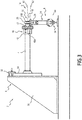
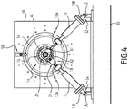
- the apparatus 2 illustrated on the Figures 3 and 4 differs from that of Figures 1 and 2 in that it is configured to test in bending a shaft 4 having an external diameter too large to cooperate directly with the connecting device 14.
- the apparatus 2 comprises an adapter 46 for reducing the diameter, the connection device 14 being mounted on the shaft 4 by means of the adapter 46.
- the adapter 46 comprises an orifice 46A for receiving the shaft 4, and an outer cylindrical bearing surface 46B for receiving the connecting device 14, the bearing surface 46B having an external diameter strictly less than the internal diameter of the orifice 46.
- the adapter 46 here comprises a tubular sleeve 48 having the orifice 46A and a stud 50 extending axially from the sleeve 48 and provided with the bearing 46B.
- the immobilization device 6 of the device 2 of the Figures 3 and 4 differs from that of Figures 1 and 2 in that it is suitable for immobilizing a shaft 4 of a rail vehicle bogie axle having a wheel 54 of a rail vehicle fitted with clamping on one end of the shaft 4, more precisely on a bearing surface of the shaft 4 intended to receive a wheel.
- the immobilization device 6 comprises a support 56 and a plurality of flanges 58 distributed in a circle and provided for gripping the peripheral edge of the wheel 54.
- a single flange 58 is shown on the Figures 3 and 4 for the sake of clarity.
- the flanges 58 are here screwed into threaded orifices of the support 56.
- the axis of the first cylinder T1 and the straight line connecting the first axis A1 and the second axis A2 form an angle between 0 and 180 ° between them.
- this angle is approximately equal to 90 °.
- the second axis A2 is located substantially between the first axis A1 and the fourth axis A4.
- the first cylinder 10 and the second cylinder 12 are controlled to move the second portion 4B of the shaft 4 along a path located in the displacement plane P (parallel to the plane of the Figures 2 and 4 ).
- the trajectory is for example a circular trajectory centered on the first axis A1 along which the shaft 4 extends at rest.
- a test method includes the installation of the shaft 4 on the device 2, the production of a displacement device rib measurement 8, the calculation of control laws of the first jack 10 and of the second jack 12 as a function measured dimensions and the desired path, then the control of the first cylinder 10 and the second cylinder 12 according to the control laws, so as to move the second portion 4B of the shaft 4 according to the desired path.
- the installation of the shaft 4 on the device 2 includes the immobilization of the first portion 4A of the shaft 4 using the immobilization device 6 and the mounting of the connection device 14 on the second portion 4B from the tree 4.
- the trajectory of the second portion 4B of the shaft 4 is repeated cyclically, with a determined number of cycles.
- the number of cycles is equal to or greater than 10 7 .
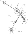
- FIGS. 5 to 8 are kinematic diagrams in perspective of apparatus for testing a bending shaft and / or a mechanical part mounted on the shaft.
- the Figure 5 represents the kinematic diagram of the device of Figures 1 to 4 .
- the third link 32 and the fourth link 34 are each a ball joint.
- the third link is a pivot link allowing rotation around the third axis A3 and / or the fourth link is a pivot link allowing rotation around the fourth axis A4.
- FIGS. 6 to 8 represent variants of the embodiment of Figures 1 to 6 .
- the Figure 6 represents a kinematic diagram of a variant in which the second axis A2 is merged with the first axis A1.
- the axis of the first cylinder T1 and the axis of the second cylinder T2 are here substantially coplanar. They are in line with each other along the first axis A1. Alternatively, they are offset relative to each other along the first axis A1.
- the first axis A1, the axis of first cylinder T1 and the axis of second cylinder are here concurrent.
- the Figure 7 represents a kinematic diagram of a variant in which the second link 18 is a ball joint between the second jack 12 and the shaft 4.
- first link 16 and the second link 18 have the same center of rotation O.
- the first axis A1, the axis of first cylinder T1 and the axis of second cylinder are here concurrent.
- the Figure 8 represents a kinematic diagram of a variant which differs from that of the Figure 7 in that the first link 16 and the second link 18 have separate centers of rotation O1, O2.
- end 12A of the second cylinder 12 is fixed to the shaft 4 in a similar manner to the end 10A of the first cylinder 10, but with an offset along the shaft 4.
- the connecting device 14 comprises for example, to form the second connection 18, a ball joint similar to the first ball joint 20 of the first connection of the Figures 1 to 4 .
- the shaft 4 passes through a ball joint of the first link 16 and the end 12A of the second jack 12 is linked to the section of the shaft projecting from the ball joint of the first link 16.
- the device 2 makes it possible to move the end of the shaft along a predetermined path, in a controlled and reliable manner. It is thus possible to carry out tests, and in particular bending fatigue tests, which are reliable.
- the device 2 is easy to implement. Hill readings taken from the displacement device, once the shaft 4 is installed, make it possible to easily calculate the control laws of the first cylinder and of the second cylinder to obtain the desired trajectory.
- the bending stress of the axle varies for example according to the load of the railway vehicle and / or according to the profile of the railway track (straight line, curve, cant ).
- the use of cylinders allows for example to simulate particular sequences of straight lines and curves.
- the apparatus 2 makes it possible to test the shaft and / or a mechanical part fitted on the shaft, such as a roller ( Figures 1 and 2 ) or a rail vehicle wheel ( Figure 3 and 4 ).
- the roller can by example used to test a particular type of rail vehicle wheel hub, without testing a complete wheel.
- the invention is not limited to the embodiments and variants described above. Other embodiments and other variants are possible.
- the first axis A1 is horizontal and the displacement plane is vertical.
- the first axis A1 is vertical and the displacement plane is horizontal.
Landscapes
- Physics & Mathematics (AREA)
- General Physics & Mathematics (AREA)
- Health & Medical Sciences (AREA)
- Life Sciences & Earth Sciences (AREA)
- Chemical & Material Sciences (AREA)
- Analytical Chemistry (AREA)
- Biochemistry (AREA)
- General Health & Medical Sciences (AREA)
- Immunology (AREA)
- Pathology (AREA)
- Investigating Strength Of Materials By Application Of Mechanical Stress (AREA)
Description
- La présente invention concerne le domaine des appareils pour tester un arbre et/ou une pièce mécanique montée sur l'arbre, par exemple une roue montée sur l'arbre.
- Des bogies de véhicule ferroviaire sont munis d'essieux, chaque essieu comprenant deux roues coaxiales portées par un arbre, chaque roue étant prévue pour rouler sur un rail respectif d'une voie ferrée. La caisse du véhicule ferroviaire est en appui sur l'arbre qui est lui-même en appui sur les roues.
- Du fait des distances entre, d'une part, les points d'appui de la caisse sur l'arbre, et, d'autre part, les roues, l'arbre est fortement sollicité en flexion. En outre, du fait de la rotation de l'arbre lorsque le bogie roule le long de la voie ferrée, l'arbre subit des cycles répétés de flexion/déflexion ce qui entraîne à terme une fatigue de l'arbre.
- Pour des raisons de sécurité, lors de la conception d'un arbre d'essieu de véhicule ferroviaire, il est nécessaire de procéder à des tests de flexion, et en particulier à des tests de fatigue en flexion.
-
EP 0 112 400 A1 ,US 4 862 738 A ,JP H04 52545 A FR 2 365 117 A1 - Il est aussi possible de tester une roue de véhicule ferroviaire emmanchée sur l'arbre.
- Un des buts de l'invention est de proposer un appareil pour tester un arbre et/ou une mécanique montée sur l'arbre, qui soit simple à mettre en œuvre, fiable et qui permette de réaliser des tests représentatifs des conditions réelles d'utilisation.
- A cet effet, l'invention propose un appareil pour tester un arbre et/ou une pièce mécanique montée sur l'arbre selon la revendication 1
- L'appareil peut comprendre une ou plusieurs des caractéristiques optionnelles des revendications 2 à 9.
- L'invention concerne aussi l'utilisation d'un appareil tel que défini ci-dessus selon la revendication 10.
- L'utilisation peut être selon la revendication 11.
- L'invention et ses avantages seront mieux compris à la lecture de la description qui va suivre, donnée uniquement à titre d'exemple, et faite en référence aux dessins annexés, sur lesquels :
- les
Figures 1 et2 sont des vues de côté et de face d'un appareil pour tester un arbre en flexion et/ou une pièce mécanique montée sur l'arbre; - les
Figures 3 et4 sont des vues de côté et de face d'un autre appareil pour tester en flexion un arbre et/ou une pièce mécanique montée sur l'arbre; et - les
Figures 5 à 8 sont des schémas cinématiques en perspective représentatifs d'appareils pour tester un arbre en flexion et/ou une pièce mécanique montée sur l'arbre. - L'appareil 2 représenté sur les
Figures 1 et2 est adapté pour réaliser un test en flexion d'un arbre, notamment un arbre d'essieu, et en particulier un arbre d'essieu de bogie de véhicule ferroviaire. - Sur les
Figures 1 et2 , un arbre 4 à tester est installé sur l'appareil 2 et prêt à être testé en flexion. L'arbre 4 est représenté au repos, i.e. non sollicité en flexion. - Dans la suite de la description, sauf indication contraire, les positions des axes géométriques et des points géométriques sont indiquées pour l'arbre 4 au repos.
- L'appareil 2 comprend un dispositif d'immobilisation 6 pour immobiliser une première portion 4A de l'arbre 4, l'arbre 4 au repos s'étendant suivant un premier axe A1, et un dispositif de déplacement 8 pour déplacer une deuxième portion 4B de l'arbre 4 perpendiculairement au premier axe A1, de manière à solliciter l'arbre 4 en flexion.
- La première portion 4A de l'arbre 4 et la deuxième portion 4B de l'arbre 4 sont espacées l'une de l'autre le long du premier axe A1 et de l'arbre 4. L'arbre 4 est sollicité en flexion entre la première portion 4A et la deuxième portion 4B de l'arbre 4. La première portion 4A et la deuxième portion 4B de l'arbre sont ici les deux portions d'extrémité opposées de l'arbre 4.
- Le dispositif de déplacement 8 est configuré pour déplacer la deuxième portion 4B de l'arbre 4 dans un plan de déplacement P sensiblement perpendiculaire au premier axe A1. Sur les
Figures 1 et2 , le premier axe A1 est sensiblement horizontal et le plan de déplacement P est sensiblement vertical. - Le dispositif de déplacement 8 comprend un premier vérin 10 s'étendant suivant un axe de premier vérin T1 sensiblement perpendiculaire au premier axe A1, un deuxième vérin 10 s'étendant suivant un axe de deuxième vérin T2 sensiblement perpendiculaire au premier axe A1, et un dispositif de liaison 14.
- Le premier vérin 10 a deux extrémités de liaison 10A, 10B opposées. Le premier vérin 10 est propre à générer une translation rectiligne d'une extrémité de liaison 10A par rapport à l'autre 10B suivant le premier axe vérin T1.
- Le deuxième vérin 12 a deux extrémités de liaison 12A, 12B opposées. Le deuxième vérin 12 est propre à générer une translation rectiligne d'une extrémité de liaison 14A par rapport à l'autre 14B suivant le deuxième axe de vérin T2.
- De préférence, le premier vérin 10 et le deuxième vérin 12 possèdent chacun de préférence deux sens de travail. En d'autres termes, chacun du premier vérin 10 et du deuxième vérin 12 est configuré pour générer sélectivement un effort de traction ou un effort de compression selon son axe de vérin T1, T2, pour respectivement rapprocher ou écarter les extrémités du vérin 10, 12 l'une de l'autre.
- L'axe de premier vérin T1 est orthogonal par rapport au premier axe A1. L'axe de deuxième vérin T2 est orthogonal par rapport au premier axe A1. L'axe de premier vérin T1 et l'axe de deuxième vérin T2 s'étendent suivant le plan de déplacement P. L'axe de premier vérin T1 et l'axe de deuxième vérin T2 font un angle non nul entre eux.
- Dans le mode de réalisation des
Figures 1 et2 , l'axe de premier vérin T1 et l'axe de deuxième vérin T2 sont sensiblement coplanaires et s'étendent dans le plan de déplacement P. - Le dispositif de liaison 14 est configuré pour être disposé entre, d'une part, le premier vérin 10 et le deuxième vérin 12, et, d'autre part, l'arbre 4, afin que le premier vérin 10 et le deuxième vérin 12 puissent solliciter l'arbre 4 perpendiculairement au premier axe A1.
- Le dispositif de liaison 14 est configuré pour réaliser, entre l'arbre 4 et l'extrémité 10A du premier vérin 10 liée à l'arbre 4, une première liaison 16 interdisant une translation relative perpendiculairement au premier axe A1 et autorisant une rotation relative autour du premier axe A1.
- De manière générale, une liaison rotule autorise trois rotations autour de trois axes orthogonaux entre eux se coupant en un centre de rotation et interdit toute translation. Une liaison linéaire annulaire autorise trois rotations et une seule translation suivant un seul axe de translation, en interdisant des translations perpendiculairement à cet axe translation, le centre de rotation coulissant suivant l'axe de rotation. Une liaison pivot autorise une rotation autour d'un seul axe de rotation et interdit toute translation. Une liaison pivot glissant autorise une rotation autour d'un seul axe de rotation, et autorise une seule translation suivant l'axe de rotation, en interdisant des translations perpendiculairement à l'axe de rotation.
- Selon l'invention, la première liaison 16 est une liaison rotule dont le centre de rotation est situé sur le premier axe, une liaison linéaire annulaire dont l'axe de translation est le premier axe A1 et le centre de rotation est situé sur le premier axe A1, une liaison pivot dont l'axe de rotation est le premier axe A1 ou une liaison pivot glissant, dont l'axe de rotation et de translation est le premier axe A1.
- Le dispositif de liaison 14 est configuré pour réaliser, entre l'arbre 4 et l'extrémité 12A du deuxième vérin liée à l'arbre 4 ou entre l'extrémité 10A du premier vérin 10 liée à l'arbre 4 par la premier liaison 16 et l'extrémité 12A du deuxième vérin 10 liée à l'arbre 4, une deuxième liaison 18 interdisant une translation relative perpendiculairement au premier axe A1 et autorisant une rotation relative autour d'un deuxième axe A2 parallèle au premier axe A1.
- Dans des modes de réalisation, la deuxième liaison 18 est une liaison rotule dont le centre de rotation est situé sur le deuxième axe A2, une liaison linéaire annulaire dont l'axe de translation est le deuxième axe A2 et le centre de rotation est situé sur le deuxième axe A2, une liaison pivot dont l'axe de rotation est le deuxième axe A2, ou une liaison pivot glissant dont l'axe de rotation et de translation est le deuxième axe A2.
- Tel qu'illustré sur les
Figures 1 et2 , le dispositif de liaison 14 est ici configuré pour réaliser la deuxième liaison 18 entre l'extrémité 10A du premier vérin 10 liée à l'arbre 4 par la première liaison 16 et l'extrémité 12A du deuxième vérin 10 liée à l'arbre 4. En outre, le deuxième axe A2 est distinct du premier axe A1. - La première liaison 16 est une liaison rotule dont le centre de rotation O est centré sur le premier axe A1.
- Le dispositif de liaison 14 comprend un premier embout 20 fixé rigidement à l'extrémité 10A du premier vérin 10, le premier embout 20 définissant un logement de rotule recevant à rotation une rotule 22 (
Figure 5 ). La rotule 22 est munie d'un orifice de réception de la deuxième portion 4B de l'arbre 4, pour le montage de la rotule 22 sur l'arbre 4. La rotule 22 est immobile en translation le long de l'arbre 4. - En variante, la première liaison 16 est une liaison linéaire annulaire. Pour ce faire, la rotule 22 est montée sur l'arbre 4 en étant mobile en translation suivant le premier axe A1 par rapport à l'arbre 4. Ceci permet d'éviter l'apparition de contraintes mécaniques lors de la sollicitation de l'arbre 4 en flexion.
- Dans ces variantes, la rotule peut être remplacée par un palier à roulement à rotule disposé dans l'embout, autorisant une rotation autour d'un axe de rotation primaire coïncidant avec le premier axe A1 et autorisant des rotations d'amplitude limitée autour de deux axe de rotation perpendiculaire à l'axe de rotation primaire.
- La deuxième liaison 18 est une liaison pivot, le deuxième axe A2 étant distinct du premier axe A1.
- Le dispositif de liaison 14 comprend un deuxième embout 24 fixé rigidement à l'extrémité 12A du deuxième vérin 10, le deuxième embout 24 étant monté pivotant sur le premier embout 20 autour du deuxième axe A2 par l'intermédiaire d'un pivot 28. L'embout 26 est par exemple un embout à chape.
- L'appareil 2 comprend un bâti 30 fixe. Le dispositif d'immobilisation 6 permet d'immobiliser la première portion 4A de l'arbre 4 par rapport au bâti. Le premier vérin 10 et le deuxième vérin 12 sont chacun agencés entre le bâti 30 et le dispositif de liaison 14 pour déplacer la deuxième portion 4B de l'arbre 4 par rapport au bâti 30 perpendiculairement au premier axe A1.
- Le premier vérin 10 a son extrémité de liaison 10A liée à l'arbre 4 par l'intermédiaire du dispositif de liaison 14, et son autre extrémité de liaison 10B liée au bâti 30 par l'intermédiaire d'une troisième liaison 32 autorisant une rotation relative autour d'un troisième axe A3 parallèle au premier axe A1 et interdisant toute translation perpendiculaire au troisième axe A3. Le troisième axe A3 est immobile.
- Le deuxième vérin 12 a son extrémité de liaison 12A liée à l'arbre 4 par l'intermédiaire du dispositif de liaison 14, et son autre extrémité 12B liée au bâti 30 par l'intermédiaire d'une quatrième liaison 34 autorisant une rotation relative autour d'un quatrième axe A4 parallèle au premier axe A1 et interdisant toute translation perpendiculairement au quatrième axe A4. Le quatrième axe A4 est immobile.
- Le premier axe A1, le deuxième axe A2, le troisième axe A3 et le quatrième axe A4 sont distincts et parallèles entre eux.
- Dans un mode de réalisation, la troisième liaison 32 et la quatrième liaison 34 sont des liaisons rotules dont les centres se situent respectivement sur le troisième axe A3 et sur le quatrième axe A4.
- En variante, la troisième liaison 32 est une liaison linéaire annulaire, dont l'axe de translation est le troisième axe A3, ou une liaison pivot ou une liaison pivot glissant dont l'axe de rotation, et le cas échéant de translation, est le troisième axe A3.
- En variante également, la quatrième liaison 34 est une liaison linéaire annulaire, dont l'axe de translation est le quatrième axe A4, ou une liaison pivot ou une liaison pivot glissant dont l'axe de rotation, et le cas échéant de translation, est le quatrième axe A4.
- La deuxième portion 4B de l'arbre 4 se déplace au cours du fonctionnement du dispositif de déplacement 8. Le troisième axe A3 et le quatrième axe A4 sont immobiles par rapport au bâti 30. Leurs positions sont invariables au cours du fonctionnement du dispositif de déplacement 8.
- Lorsque l'arbre 4 est au repos, l'axe de premier vérin T1 coupe le premier axe A1 et le troisième axe A3, et l'axe de deuxième vérin T2 coupe le deuxième axe A2 et le quatrième axe A4.
- Le premier vérin 10 et le deuxième vérin 12 convergent l'un vers l'autre en direction du premier axe A1. La distance entre le premier axe A1 et le deuxième axe A2 est strictement inférieure à la distance entre le troisième axe A3 et le quatrième axe A4.
- Les extrémités de liaison 10A, 12A du premier vérin 10 et du deuxième vérin 12 liées au dispositif de liaison 14 sont plus proches l'une de l'autre que les extrémités de liaison 10B, 12B opposées du premier vérin 10 et du deuxième vérin 12 montées à rotation autour respectivement du troisième axe A3 et du quatrième axe A4.
- Le premier vérin 10 et le deuxième vérin 12 comprennent chacun un corps de vérin 36 et une tige de vérin 38 coulissant par rapport au corps de vérin 36, respectivement suivant l'axe de premier vérin T1 et l'axe de deuxième vérin T2.
- Une extrémité de liaison 10A, 12A de chacun du premier vérin 10 et du deuxième vérin 12 est l'extrémité de la tige de vérin 38 de ce vérin opposée au corps de vérin 36 de ce vérin, l'autre extrémité de liaison 10B, 12B de chacun du premier vérin 10 et du deuxième vérin 12 étant l'extrémité du corps de vérin 36 de ce vérin opposée à la tige de vérin 38.
- La tige de vérin 38 de chacun du premier vérin 10 et du deuxième vérin 12 est liée au dispositif de liaison 14 et le corps de vérin 36 de chacun du premier vérin 10 et du deuxième vérin 12 est monté rotatif autour d'un axe fixe A3, A4. En variante, la configuration du premier vérin 10 et/ou la configuration du deuxième vérin 12 est inversée.
- Dans un mode de réalisation, le premier vérin 10 et le deuxième vérin 12 sont des vérins hydrauliques. Un vérin hydraulique utilise un liquide sous pression pour déplacer un piston à l'intérieur du corps de vérin, la tige de vérin étant solidaire du piston.
- Dans un autre mode de réalisation, le premier vérin 10 et le deuxième vérin 12 sont des vérins électriques. Un vérin électrique utilise par exemple un ensemble vis/écrou et un moteur électrique pour entraîner la vis et l'écrou en rotation l'un par rapport à l'autre et déplacer la tige de vérin en translation par rapport au corps de vérin.
- Comme illustré sur les
Figures 1 et2 , le dispositif d'immobilisation 6 comprend un support 40 et portant un galet 42 fretté sur une portée de l'arbre 4 destinée à recevoir une roue de véhicule ferroviaire, le galet 42 étant monté fixe sur la support 40. Par « fretté », on entend que le galet 42 est emmanché avec serrage sur la portée de l'arbre 4 destinée à recevoir la roue. Dans une variante possible, le galet 42 est remplacé par une roue. L'utilisation d'un galet 42 ou d'une roue montée sur l'arbre permet de reproduire les conditions d'utilisation de l'arbre 4, notamment avec les contraintes générées à l'interface arbre/roue. - Comme illustré sur les
Figures 1 et2 , le bâti 30 se présente ici sous la forme d'une plaque, aussi nommée « marbre ». Le support 40 présente la forme d'un montant s'étendant vers le haut à partir du bâti 30 et portant le galet 42 à son extrémité supérieure. D'autres bâti 30 et d'autres dispositifs d'immobilisation 6 sont envisageables. - Par ailleurs, comme illustré sur les
Figures 1 et2 , l'arbre 4 possède ici un diamètre externe trop petit pour coopérer directement avec le dispositif de liaison 14. - L'appareil 2 comprend un adaptateur 44 agrandisseur de diamètre, le dispositif de liaison 14 étant monté sur l'arbre 4 par l'intermédiaire de l'adaptateur 44. L'adaptateur 44 présente un orifice pour recevoir l'arbre 4 et une portée cylindrique pour recevoir le dispositif de liaison 14, la portée possédant un diamètre externe strictement supérieur au diamètre interne de l'orifice.
- L'adaptateur 44 se présente ici sous la forme d'un manchon tubulaire enfilé sur l'arbre 4, l'embout 24 du dispositif de liaison 14 étant monté sur l'adaptateur 44.
- L'appareil 2 illustré sur les
Figures 3 et4 diffère de celui desFigures 1 et2 en ce qu'il est configuré pour tester en flexion un arbre 4 possédant un diamètre externe trop grand pour coopérer directement avec le dispositif de liaison 14. - L'appareil 2 comprend un adaptateur 46 réducteur de diamètre, le dispositif de liaison 14 étant monté sur l'arbre 4 par l'intermédiaire de l'adaptateur 46. L'adaptateur 46 comprend un orifice 46A pour recevoir l'arbre 4, et une portée 46B cylindrique externe pour recevoir le dispositif de liaison 14, la portée 46B possédant un diamètre externe strictement inférieur au diamètre interne de l'orifice 46.
- L'adaptateur 46 comprend ici un manchon 48 tubulaire possédant l'orifice 46A et un téton 50 s'étendant axialement à partir du manchon 48 et muni de la portée 46B.
- Par ailleurs, le dispositif d'immobilisation 6 de l'appareil 2 des
Figures 3 et4 diffère de celui desFigures 1 et2 en ce qu'il est adapté pour immobiliser un arbre 4 d'essieu de bogie de véhicule ferroviaire ayant une roue 54 de véhicule ferroviaire emmanchée avec serrage sur une extrémité de l'arbre 4, plus précisément sur une portée de l'arbre 4 destinée à recevoir une roue. - A cet effet, le dispositif d'immobilisation 6 comprend un support 56 et une pluralité de brides 58 réparties en cercle et prévues pour agripper le bord périphérique de la roue 54. Une seule bride 58 est représentée sur les
Figures 3 et4 pour des raisons de clarté. Les brides 58 sont ici vissées dans des orifices taraudés du support 56. - En vue suivant le premier axe A1 (
Figures 2 et4 ), l'axe de premier vérin T1 et le segment de droite reliant le premier axe A1 et le deuxième axe A2, forment entre eux un angle compris entre 0 et 180°. De préférence, cet angle est environ égal à 90°. - En vue suivant le premier axe A1 (
Figures 2 et4 ), le deuxième axe A2 est situé sensiblement entre le premier axe A1 et le quatrième axe A4. Le segment de droite reliant le premier axe A1 et le deuxième axe A2, d'une part, et le segment de droite reliant le deuxième axe A2 et le quatrième axe A4, d'autre part, font entre eux un angle compris entre 90° et 180°, de préférence un angle compris entre 120° et 180°. - En cours de fonctionnement, le premier vérin 10 et le deuxième vérin 12 sont commandés pour déplacer la deuxième portion 4B de l'arbre 4 suivant une trajectoire située dans le plan de déplacement P (parallèle au plan des
Figures 2 et4 ). Pour réaliser des essais de fatigue en flexion, la trajectoire est par exemple une trajectoire circulaire centrée sur le premier axe A1 selon lequel l'arbre 4 s'étend au repos. - Une procédé de test comprend l'installation de l'arbre 4 sur l'appareil 2, la réalisation d'un relevé de côtes de dispositif de déplacement 8, le calcul de lois de commande du premier vérin 10 et du deuxième vérin 12 en fonction des côtes mesurées et de la trajectoire souhaitée, puis la commande du premier vérin 10 et du deuxième vérin 12 en fonction des lois de commandes, de telle manière à déplacer la deuxième portion 4B de l'arbre 4 selon la trajectoire souhaitée.
- L'installation de l'arbre 4 sur l'appareil 2 comprend l'immobilisation de la première portion 4A de l'arbre 4 à l'aide du dispositif d'immobilisation 6 et le montage du dispositif de liaison 14 sur la deuxième portion 4B de l'arbre 4.
- Lors d'un test de fatigue en flexion, la trajectoire de la deuxième portion 4B de l'arbre 4 est répétée de manière cyclique, avec un nombre de cycles déterminé. Typiquement, pour un arbre 4 d'essieu de bogie de véhicule ferroviaire, le nombre de cycles est égal ou supérieur à 107.
- Les
Figures 5 à 8 sont des schémas cinématiques en perspective d'appareils de test d'un arbre en flexion et/ou d'une pièce mécanique montée sur l'arbre. - La
Figure 5 représente le schéma cinématique de l'appareil desFigures 1 à 4 . La troisième liaison 32 et la quatrième liaison 34 sont chacune une liaison rotule. En variante, la troisième liaison est une liaison pivot autorisant une rotation autour du troisième axe A3 et/ou la quatrième liaison est une liaison pivot autorisant une rotation autour du quatrième axe A4. - Les
Figures 6 à 8 représentent des variantes du mode de réalisation desFigures 1 à 6 . - La
Figure 6 représente un schéma cinématique d'une variante dans laquelle le deuxième axe A2 est confondu avec le premier axe A1. L'axe de premier vérin T1 et l'axe de deuxième vérin T2 sont ici sensiblement coplanaire. Ils sont au droit l'un de l'autre le long du premier axe A1. En variante, ils sont décalés l'un par rapport à l'autre suivant le premier axe A1. - Le premier axe A1, l'axe de premier vérin T1 et l'axe de deuxième vérin sont ici concourants.
- La
Figure 7 représente un schéma cinématique d'une variante dans laquelle la deuxième liaison 18 est une liaison rotule entre le deuxième vérin 12 et l'arbre 4. - Dans un mode de réalisation, la première liaison 16 et la deuxième liaison 18 possèdent le même centre de rotation O. Pour ce faire, il est possible de prévoir une seule rotule et deux pièces définissant chacune une partie respective du logement de rotule, les deux pièces liées entre elles par une liaison pivot autorisant une rotation autour du premier axe A1, une pièce étant liée rigidement à l'extrémité 10A du premier vérin 10 et l'autre pièce étant montée rigidement à l'extrémité 12A du deuxième vérin 12.
- Le premier axe A1, l'axe de premier vérin T1 et l'axe de deuxième vérin sont ici concourants.
- La
Figure 8 représente un schéma cinématique d'une variante qui diffère de celle de laFigure 7 en ce que la première liaison 16 et la deuxième liaison 18 possèdent des centres de rotation O1, O2 distincts. - En pratique pour réaliser une telle variante, il est possible que l'extrémité 12A du deuxième vérin 12 soit fixée sur l'arbre 4 de manière analogue à l'extrémité 10A du premier vérin 10, mais avec un décalage le long de l'arbre 4.
- Le dispositif de liaison 14 comprend par exemple, pour former la deuxième liaison 18, un embout à rotule similaire au premier embout 20 à rotule de la première liaison des
Figures 1 à 4 . - Dans un mode de réalisation, l'arbre 4 traverse une rotule de la première liaison 16 et l'extrémité 12A du deuxième vérin 12 est liée au tronçon de l'arbre dépassant de la rotule de la première liaison 16.
- L'appareil 2 permet de déplacer l'extrémité de l'arbre selon une trajectoire prédéterminée, de manière contrôlée et fiable. Il est ainsi possible de réaliser des tests, et en particulier des tests de fatigue en flexion, qui sont fiables.
- L'appareil 2 est facile à mettre en œuvre. Des relevés de côte pris sur le dispositif de déplacement, une fois l'arbre 4 installé, permettent de calculer facilement les lois de commande du premier vérin et du deuxième vérin pour obtenir la trajectoire souhaitée.
- L'utilisation de vérins permet de maîtriser les efforts appliqués sur l'arbre, et ainsi de mieux maîtriser les paramètres du test.
- L'utilisation de vérins permet notamment de mettre en œuvre des cycles particuliers reproduisant les conditions d'utilisation réelles d'un essieu ferroviaire.
- En effet, en pratique, la sollicitation en flexion de l'essieu varie par exemple selon la charge du véhicule ferroviaire et/ou selon le profil de la voie ferrée (ligne droite, courbe, dévers...). L'utilisation de vérins permet par exemple de simuler des enchaînements particuliers de lignes droites et de courbes.
- Dans ce qui précède, on a décrit le test en flexion d'un arbre. Ceci étant, l'appareil 2 permet de tester l'arbre et/ou une pièce mécanique emmanchée sur l'arbre, comme un galet (
Figures 1 et2 ) ou une roue de véhicule ferroviaire (Figure 3 et4 ). Le galet peut par exemple servir à tester un type particulier du moyeu de roue de véhicule ferroviaire, sans tester une roue complète. - Le test d'un galet ou d'une roue par sollicitation en flexion de l'arbre permet de reproduire les conditions de fonctionnement d'un essieu de véhicule ferroviaire, et notamment l'interaction entre l'arbre et le galet ou la roue emmanché sur l'arbre.
- L'invention n'est pas limitée aux modes de réalisation et variantes décrits ci-dessus. D'autres modes de réalisation et d'autres variantes sont envisageables.
- Par exemple, sur les
Figures 1 à 8 , le premier axe A1 est horizontal et le plan de déplacement est vertical. En variante, le premier axe A1 est vertical et le plan de déplacement est horizontal.
Claims (11)
- Appareil pour tester un arbre (4) et/ou une pièce mécanique montée sur l'arbre, l'appareil comprenant un dispositif d'immobilisation pour immobiliser une première portion (4A) de l'arbre, l'arbre (4) immobilisé et au repos s'étendant suivant un premier axe (A1), et un dispositif de déplacement pour déplacer une deuxième portion (4B) de l'arbre sensiblement perpendiculairement au premier axe (A1), de manière à solliciter l'arbre (4) en flexion,
dans lequel le dispositif de déplacement comprend un premier vérin (10) agencé suivant un premier axe de vérin (T1) sensiblement perpendiculaire au premier axe (A1), un deuxième vérin (12) agencé suivant un deuxième axe de vérin (T2) sensiblement perpendiculaire au premier axe, et un dispositif de liaison (14) pour lier le premier vérin (10) et le deuxième vérin (12) à l'arbre (4),
caractérisé en ce que le dispositif de liaison (14) est configuré pour réaliser, entre l'arbre (4) et une extrémité du premier vérin (10), une première liaison (16) interdisant une translation relative perpendiculairement au premier axe (A1) et autorisant une rotation relative autour du premier axe (A1), la première liaison (16) étant une liaison rotule dont le centre de rotation est situé sur le premier axe (A1), une liaison linéaire annulaire dont l'axe de translation est le premier axe (A1) et le centre de rotation est situé sur le premier axe (A1), une liaison pivot dont l'axe de rotation est le premier axe (A1) ou une liaison pivot glissant, dont l'axe de rotation et de translation est le premier axe (A1), et pour réaliser, entre l'arbre (4) et une extrémité du deuxième vérin (12) ou entre l'extrémité du premier vérin (10) liée à l'arbre (4) et une extrémité du deuxième vérin (12), une deuxième liaison (18) interdisant une translation relative perpendiculairement au premier axe (A1) et autorisant une rotation relative autour d'un deuxième axe (A2) parallèle au premier axe (A1). - Appareil selon la revendication 1, dans lequel la première liaison (16) comprend un embout liée rigidement à une extrémité du premier vérin (10), l'embout définissant un logement de rotule recevant une rotule destinée à être montée sur l'arbre (4) en étant centrée sur le premier axe (A1).
- Appareil selon l'une quelconque de revendications précédentes, dans lequel le deuxième axe (A2) est distinct du premier axe (A1).
- Appareil selon l'une quelconque de revendications 1 à 2, dans lequel le deuxième axe (A2) coïncide avec le premier axe (A1).
- Appareil selon l'une quelconque de revendications précédentes, dans lequel la deuxième liaison (18) est une liaison pivot dont l'axe de rotation est le deuxième axe (A2).
- Appareil selon l'une quelconque de revendications 1 à 4, dans lequel la deuxième liaison (18) est une liaison rotule ou une liaison linéaire annulaire.
- Appareil selon l'une quelconque des revendications précédentes, dans lequel, l'arbre (4) étant au repos, le premier axe de vérin (T1) coupe le premier axe (A1) et/ou le deuxième axe de vérin (T2) coupe le premier axe (A1).
- Appareil selon l'une quelconque des revendications précédentes, comprenant au moins un adaptateur (46) comprenant un orifice pour recevoir la deuxième portion (4B) de l'arbre (4) et une portée cylindrique pour le montage du dispositif de liaison (14), la portée cylindrique présentant un diamètre externe strictement supérieur ou strictement inférieur au diamètre interne de l'orifice.
- Appareil selon l'une quelconque des revendications précédentes, dans lequel le dispositif d'immobilisation est configuré pour immobiliser une pièce mécanique montée sur la première portion (4A) de l'arbre, notamment un galet ou une roue de véhicule ferroviaire emmanchée sur le première portion (4A).
- Utilisation d'un appareil, caractérisé en ce que l'appareil est selon l'une quelconque des revendications précédentes pour tester en flexion un arbre (4), en particulier un arbre d'essieu de bogie de véhicule ferroviaire et/ou tester une pièce mécanique montée sur l'arbre, en particulier un galet ou une roue emmanchée sur l'arbre.
- Utilisation selon la revendication 10, comprenant :- l'installation de l'arbre (4) sur l'appareil,- le relevé de côtes du dispositif de déplacement, l'arbre (4) étant au repos,- le calcul de lois de commande du premier vérin (10) et du deuxième vérin (12) en fonction des côtes relevées et d'une trajectoire souhaitée de la deuxième portion (4B) de l'arbre, et- la commande du premier vérin et du deuxième vérin en fonction des lois de commandes calculées.
Priority Applications (1)
| Application Number | Priority Date | Filing Date | Title |
|---|---|---|---|
| PL17793894T PL3529582T3 (pl) | 2016-10-21 | 2017-10-23 | Aparatura do badania wału i/lub części mechanicznej zamontowanej na wale oraz zastosowanie takiej aparatury |
Applications Claiming Priority (2)
| Application Number | Priority Date | Filing Date | Title |
|---|---|---|---|
| FR1660234A FR3057955A1 (fr) | 2016-10-21 | 2016-10-21 | Appareil pour tester un arbre et/ou une piece mecanique montee sur l'arbre et utilisation d'un tel appareil |
| PCT/EP2017/077000 WO2018073451A1 (fr) | 2016-10-21 | 2017-10-23 | Appareil pour tester un arbre et/ou une piece mecanique montee sur l'arbre et utilisation d'un tel appareil |
Publications (2)
| Publication Number | Publication Date |
|---|---|
| EP3529582A1 EP3529582A1 (fr) | 2019-08-28 |
| EP3529582B1 true EP3529582B1 (fr) | 2020-07-15 |
Family
ID=57590670
Family Applications (1)
| Application Number | Title | Priority Date | Filing Date |
|---|---|---|---|
| EP17793894.1A Active EP3529582B1 (fr) | 2016-10-21 | 2017-10-23 | Appareil pour tester un arbre et/ou une piece mecanique montee sur l'arbre et utilisation d'un tel appareil |
Country Status (9)
| Country | Link |
|---|---|
| US (1) | US11226262B2 (fr) |
| EP (1) | EP3529582B1 (fr) |
| KR (1) | KR102445004B1 (fr) |
| CN (1) | CN110770562B (fr) |
| CA (1) | CA3040801A1 (fr) |
| ES (1) | ES2817430T3 (fr) |
| FR (1) | FR3057955A1 (fr) |
| PL (1) | PL3529582T3 (fr) |
| WO (1) | WO2018073451A1 (fr) |
Families Citing this family (3)
| Publication number | Priority date | Publication date | Assignee | Title |
|---|---|---|---|---|
| KR102344942B1 (ko) * | 2020-04-03 | 2021-12-28 | 한화솔루션 주식회사 | 가스 리프트의 체결포인트 검증이 가능한 지그 |
| CN114577628A (zh) * | 2022-02-21 | 2022-06-03 | 中信戴卡股份有限公司 | 一种镁合金车轮高温弯曲疲劳试验设备 |
| CN115165334B (zh) * | 2022-07-12 | 2026-02-03 | 中国电子科技集团公司第三十八研究所 | 雷达天线复合加载试验装置 |
Family Cites Families (31)
| Publication number | Priority date | Publication date | Assignee | Title |
|---|---|---|---|---|
| US3305935A (en) * | 1964-09-29 | 1967-02-28 | Lynch Corp | Vehicle test system |
| FR2188824A5 (fr) * | 1972-06-01 | 1974-01-18 | Peugeot & Renault | |
| FR2232755B1 (fr) * | 1973-06-06 | 1976-04-23 | Peugeot & Renault | |
| DE7629275U1 (de) * | 1976-09-20 | 1988-05-19 | Carl Schenck Ag, 6100 Darmstadt | Prüfeinrichtung für Fahrzeugachsen, Radaufhängungen und ähnliche Bauteile |
| US4263809A (en) * | 1979-07-02 | 1981-04-28 | Mts Systems Corporation | Tetraxial vehicle test fixture |
| EP0112400B1 (fr) * | 1982-12-23 | 1988-02-24 | Carl Schenck Ag | Dispositif d'introduction de forces dans une structure, en particulier un essieu d'une voiture, la suspension de roues etc. |
| US4501139A (en) * | 1983-08-26 | 1985-02-26 | Mts Systems Corporation | Test system for testing front wheel drive components of automobiles |
| US4656872A (en) * | 1986-04-14 | 1987-04-14 | Fischer Glenn N | Wrap-around bend test method and apparatus |
| US4862738A (en) * | 1987-08-20 | 1989-09-05 | Allied-Signal, Inc. | Test system for wheel bearings |
| US5018757A (en) * | 1989-06-05 | 1991-05-28 | Mitsubishi Jidosha Kogyo Kabushiki Kaisha | Steering angle control apparatus for vehicle |
| US5083453A (en) * | 1990-02-01 | 1992-01-28 | Mts Systems Corporation | Linkage for vehicle simulator |
| JP2843118B2 (ja) * | 1990-06-20 | 1999-01-06 | 株式会社鷺宮製作所 | 軸疲労試験装置 |
| US5072611A (en) * | 1990-09-04 | 1991-12-17 | The B. F. Goodrich Company | Apparatus and method for testing wheels, bearings and lubricants |
| FR2707389B1 (fr) * | 1993-07-09 | 1995-10-06 | Valdunes | Procédé de détermination du tracé de la section axiale d'une roue et roue obtenue. |
| US5533403A (en) * | 1994-11-10 | 1996-07-09 | Mts Systems Corporation | Loading assembly for a vehicle spindle test fixture |
| US5806634A (en) * | 1996-11-12 | 1998-09-15 | Westinghouse Air Brake Company | Offset arrangement for brake system proportionalization lever |
| JP2851272B2 (ja) * | 1997-03-10 | 1999-01-27 | 本田技研工業株式会社 | 操舵トルクセンサ付き可変舵角比操舵装置 |
| US6895830B2 (en) * | 2001-04-05 | 2005-05-24 | Rochester Institute Of Technology | System and method for testing linkages |
| US6865954B2 (en) * | 2003-03-10 | 2005-03-15 | Spinecore, Inc. | Joint simulator testing machine |
| GB0605345D0 (en) * | 2006-03-16 | 2006-04-26 | Airbus Uk Ltd | Testing strut assembly |
| GB0609049D0 (en) * | 2006-05-08 | 2006-06-14 | Airbus Uk Ltd | Method and apparatus for applying bending load to an axle of an aircraft landing gear |
| KR100799334B1 (ko) * | 2006-10-18 | 2008-01-30 | 한국철도기술연구원 | 철도차량 차축압입부위의 결함 탐상장치 |
| WO2009135136A2 (fr) * | 2008-05-02 | 2009-11-05 | Alliance For Sustainable Energy, Llc | Système d’essai d’excitation de base au moyen d’éléments de type ressort pour monter de manière pivotante des pales d’éolienne |
| JP5137789B2 (ja) * | 2008-11-18 | 2013-02-06 | 独立行政法人交通安全環境研究所 | 模擬車輪および車両試験装置 |
| DE102010027897B4 (de) * | 2010-04-19 | 2013-02-28 | Sven Henze | Schwingungsprüfeinrichtung |
| CN103175702B (zh) | 2011-12-20 | 2015-04-22 | 南车青岛四方机车车辆股份有限公司 | 轮轴疲劳试验装置及其方法 |
| CN202382948U (zh) * | 2011-12-20 | 2012-08-15 | 南车青岛四方机车车辆股份有限公司 | 轮轴疲劳试验装置 |
| DK2728332T3 (en) * | 2012-10-31 | 2019-01-14 | Siemens Ag | Testing Facility |
| EP2767814B1 (fr) * | 2013-02-13 | 2019-08-28 | MBDA Deutschland GmbH | Banc d'essai de charge pour système de commande avec un arbre de sortie |
| EP2927660B1 (fr) * | 2014-04-04 | 2016-10-12 | Prisma Engineering Maschinen- und Motorentechnik GmbH | Dispositif d'essai de charge d'échantillons rotatifs |
| DE102014106086A1 (de) * | 2014-04-30 | 2015-11-05 | Knorr-Bremse Systeme für Schienenfahrzeuge GmbH | Rollenprüfstand und Betriebsverfahren für einen Rollenprüfstand |
-
2016
- 2016-10-21 FR FR1660234A patent/FR3057955A1/fr not_active Withdrawn
-
2017
- 2017-10-23 ES ES17793894T patent/ES2817430T3/es active Active
- 2017-10-23 EP EP17793894.1A patent/EP3529582B1/fr active Active
- 2017-10-23 PL PL17793894T patent/PL3529582T3/pl unknown
- 2017-10-23 US US16/343,733 patent/US11226262B2/en not_active Expired - Fee Related
- 2017-10-23 CA CA3040801A patent/CA3040801A1/fr active Pending
- 2017-10-23 KR KR1020197011191A patent/KR102445004B1/ko active Active
- 2017-10-23 WO PCT/EP2017/077000 patent/WO2018073451A1/fr not_active Ceased
- 2017-10-23 CN CN201780068466.7A patent/CN110770562B/zh not_active Expired - Fee Related
Non-Patent Citations (1)
| Title |
|---|
| None * |
Also Published As
| Publication number | Publication date |
|---|---|
| CN110770562B (zh) | 2022-04-01 |
| KR102445004B1 (ko) | 2022-09-19 |
| CA3040801A1 (fr) | 2018-04-26 |
| FR3057955A1 (fr) | 2018-04-27 |
| PL3529582T3 (pl) | 2021-01-11 |
| US11226262B2 (en) | 2022-01-18 |
| KR20190123717A (ko) | 2019-11-01 |
| EP3529582A1 (fr) | 2019-08-28 |
| ES2817430T3 (es) | 2021-04-07 |
| US20190271613A1 (en) | 2019-09-05 |
| WO2018073451A1 (fr) | 2018-04-26 |
| CN110770562A (zh) | 2020-02-07 |
Similar Documents
| Publication | Publication Date | Title |
|---|---|---|
| FR2757440A1 (fr) | Plateforme hexapode et dispositifs d'articulation spherique utilisables pour sa realisation | |
| FR3002799A1 (fr) | Cellule de mesure d'effort pour nacelle elevatrice et nacelle elevatrice comprenant une telle cellule | |
| EP2997345B1 (fr) | Banc d'essai en fatigue oligocyclique ou en fatigue oligocyclique et polycyclique | |
| WO2018073451A1 (fr) | Appareil pour tester un arbre et/ou une piece mecanique montee sur l'arbre et utilisation d'un tel appareil | |
| FR2967635A1 (fr) | Bogie de vehicule ferroviaire comprenant un dispositif de freinage a courants de foucault | |
| EP3931064B1 (fr) | Système d'immobilisation d'un robot médical | |
| FR2972389A1 (fr) | Dispositif de liaison d'une roue a une structure de vehicule automobile | |
| FR2851741A1 (fr) | Jambe de suspension comprenant un tampon de butee | |
| WO2022207916A1 (fr) | Dispositif de mesure dynamométrique | |
| FR3031722A1 (fr) | Dispositif de determination du couple applique a un axe de pedalier | |
| FR2954826A1 (fr) | Table d'essai destinee au controle de tarage d'une soupape | |
| FR2645643A1 (fr) | Dispositif pour appliquer une charge d'intensite et d'orientation determinees et reglables a au moins un roulement a bille associe a un arbre tournant | |
| EP2261588B1 (fr) | Dispositif de pointage en gisement d'une tourelle | |
| FR2917079A1 (fr) | Banc d'essais dynamique de vehicule automobile,comportant un pont elevateur | |
| FR2871570A1 (fr) | Dispositif de mesure de la rigidite d'une paroi et procede correspondant | |
| FR2976519A1 (fr) | Dispositif de liaison d'une roue a une structure de vehicule automobile | |
| FR2565550A1 (fr) | Appareil a gouverner un navire comportant un verin supporte par une rotule a jeu axial ajustable | |
| CA1328084C (fr) | Dispositif de freinage d'un essieu d'un vehicule ferroviaire | |
| WO2024209146A1 (fr) | Procédé et dispositif de détermination de charge pour plate-forme de travail de nacelle élévatrice | |
| EP3362304B1 (fr) | Agencement pour la liaison d'un porte fusée à un élément de structure de véhicule automobile | |
| FR3112608A1 (fr) | Banc d’essai et son procédé de mise en œuvre | |
| FR2916272A1 (fr) | Procede et dispositif de mesure du couple residuel sur une roue de vehicule. | |
| FR2940436A1 (fr) | Dispositif d'etalonnage d'appareils de mesure de contraintes | |
| FR2924052A1 (fr) | Dispositif d'inclinaison asservie pour un vehicule terrestre etroit | |
| CH261421A (fr) | Instrument de mesure. |
Legal Events
| Date | Code | Title | Description |
|---|---|---|---|
| STAA | Information on the status of an ep patent application or granted ep patent |
Free format text: STATUS: UNKNOWN |
|
| STAA | Information on the status of an ep patent application or granted ep patent |
Free format text: STATUS: THE INTERNATIONAL PUBLICATION HAS BEEN MADE |
|
| PUAI | Public reference made under article 153(3) epc to a published international application that has entered the european phase |
Free format text: ORIGINAL CODE: 0009012 |
|
| STAA | Information on the status of an ep patent application or granted ep patent |
Free format text: STATUS: REQUEST FOR EXAMINATION WAS MADE |
|
| 17P | Request for examination filed |
Effective date: 20190419 |
|
| AK | Designated contracting states |
Kind code of ref document: A1 Designated state(s): AL AT BE BG CH CY CZ DE DK EE ES FI FR GB GR HR HU IE IS IT LI LT LU LV MC MK MT NL NO PL PT RO RS SE SI SK SM TR |
|
| AX | Request for extension of the european patent |
Extension state: BA ME |
|
| DAV | Request for validation of the european patent (deleted) | ||
| DAX | Request for extension of the european patent (deleted) | ||
| REG | Reference to a national code |
Ref country code: DE Ref legal event code: R079 Ref document number: 602017019944 Country of ref document: DE Free format text: PREVIOUS MAIN CLASS: G01M0013020000 Ipc: G01M0013027000 |
|
| GRAP | Despatch of communication of intention to grant a patent |
Free format text: ORIGINAL CODE: EPIDOSNIGR1 |
|
| STAA | Information on the status of an ep patent application or granted ep patent |
Free format text: STATUS: GRANT OF PATENT IS INTENDED |
|
| RIC1 | Information provided on ipc code assigned before grant |
Ipc: G01N 3/20 20060101ALI20200219BHEP Ipc: G01M 13/027 20190101AFI20200219BHEP |
|
| INTG | Intention to grant announced |
Effective date: 20200313 |
|
| GRAS | Grant fee paid |
Free format text: ORIGINAL CODE: EPIDOSNIGR3 |
|
| GRAA | (expected) grant |
Free format text: ORIGINAL CODE: 0009210 |
|
| STAA | Information on the status of an ep patent application or granted ep patent |
Free format text: STATUS: THE PATENT HAS BEEN GRANTED |
|
| AK | Designated contracting states |
Kind code of ref document: B1 Designated state(s): AL AT BE BG CH CY CZ DE DK EE ES FI FR GB GR HR HU IE IS IT LI LT LU LV MC MK MT NL NO PL PT RO RS SE SI SK SM TR |
|
| REG | Reference to a national code |
Ref country code: CH Ref legal event code: EP Ref country code: GB Ref legal event code: FG4D Free format text: NOT ENGLISH |
|
| REG | Reference to a national code |
Ref country code: IE Ref legal event code: FG4D Free format text: LANGUAGE OF EP DOCUMENT: FRENCH |
|
| REG | Reference to a national code |
Ref country code: DE Ref legal event code: R096 Ref document number: 602017019944 Country of ref document: DE |
|
| REG | Reference to a national code |
Ref country code: AT Ref legal event code: REF Ref document number: 1291551 Country of ref document: AT Kind code of ref document: T Effective date: 20200815 |
|
| REG | Reference to a national code |
Ref country code: SE Ref legal event code: TRGR |
|
| REG | Reference to a national code |
Ref country code: LT Ref legal event code: MG4D |
|
| REG | Reference to a national code |
Ref country code: NL Ref legal event code: MP Effective date: 20200715 |
|
| PG25 | Lapsed in a contracting state [announced via postgrant information from national office to epo] |
Ref country code: NO Free format text: LAPSE BECAUSE OF FAILURE TO SUBMIT A TRANSLATION OF THE DESCRIPTION OR TO PAY THE FEE WITHIN THE PRESCRIBED TIME-LIMIT Effective date: 20201015 Ref country code: GR Free format text: LAPSE BECAUSE OF FAILURE TO SUBMIT A TRANSLATION OF THE DESCRIPTION OR TO PAY THE FEE WITHIN THE PRESCRIBED TIME-LIMIT Effective date: 20201016 Ref country code: PT Free format text: LAPSE BECAUSE OF FAILURE TO SUBMIT A TRANSLATION OF THE DESCRIPTION OR TO PAY THE FEE WITHIN THE PRESCRIBED TIME-LIMIT Effective date: 20201116 Ref country code: BG Free format text: LAPSE BECAUSE OF FAILURE TO SUBMIT A TRANSLATION OF THE DESCRIPTION OR TO PAY THE FEE WITHIN THE PRESCRIBED TIME-LIMIT Effective date: 20201015 Ref country code: FI Free format text: LAPSE BECAUSE OF FAILURE TO SUBMIT A TRANSLATION OF THE DESCRIPTION OR TO PAY THE FEE WITHIN THE PRESCRIBED TIME-LIMIT Effective date: 20200715 Ref country code: LT Free format text: LAPSE BECAUSE OF FAILURE TO SUBMIT A TRANSLATION OF THE DESCRIPTION OR TO PAY THE FEE WITHIN THE PRESCRIBED TIME-LIMIT Effective date: 20200715 Ref country code: HR Free format text: LAPSE BECAUSE OF FAILURE TO SUBMIT A TRANSLATION OF THE DESCRIPTION OR TO PAY THE FEE WITHIN THE PRESCRIBED TIME-LIMIT Effective date: 20200715 |
|
| PG25 | Lapsed in a contracting state [announced via postgrant information from national office to epo] |
Ref country code: LV Free format text: LAPSE BECAUSE OF FAILURE TO SUBMIT A TRANSLATION OF THE DESCRIPTION OR TO PAY THE FEE WITHIN THE PRESCRIBED TIME-LIMIT Effective date: 20200715 Ref country code: RS Free format text: LAPSE BECAUSE OF FAILURE TO SUBMIT A TRANSLATION OF THE DESCRIPTION OR TO PAY THE FEE WITHIN THE PRESCRIBED TIME-LIMIT Effective date: 20200715 Ref country code: IS Free format text: LAPSE BECAUSE OF FAILURE TO SUBMIT A TRANSLATION OF THE DESCRIPTION OR TO PAY THE FEE WITHIN THE PRESCRIBED TIME-LIMIT Effective date: 20201115 |
|
| PG25 | Lapsed in a contracting state [announced via postgrant information from national office to epo] |
Ref country code: NL Free format text: LAPSE BECAUSE OF FAILURE TO SUBMIT A TRANSLATION OF THE DESCRIPTION OR TO PAY THE FEE WITHIN THE PRESCRIBED TIME-LIMIT Effective date: 20200715 |
|
| REG | Reference to a national code |
Ref country code: ES Ref legal event code: FG2A Ref document number: 2817430 Country of ref document: ES Kind code of ref document: T3 Effective date: 20210407 |
|
| REG | Reference to a national code |
Ref country code: DE Ref legal event code: R097 Ref document number: 602017019944 Country of ref document: DE |
|
| PG25 | Lapsed in a contracting state [announced via postgrant information from national office to epo] |
Ref country code: EE Free format text: LAPSE BECAUSE OF FAILURE TO SUBMIT A TRANSLATION OF THE DESCRIPTION OR TO PAY THE FEE WITHIN THE PRESCRIBED TIME-LIMIT Effective date: 20200715 Ref country code: RO Free format text: LAPSE BECAUSE OF FAILURE TO SUBMIT A TRANSLATION OF THE DESCRIPTION OR TO PAY THE FEE WITHIN THE PRESCRIBED TIME-LIMIT Effective date: 20200715 Ref country code: DK Free format text: LAPSE BECAUSE OF FAILURE TO SUBMIT A TRANSLATION OF THE DESCRIPTION OR TO PAY THE FEE WITHIN THE PRESCRIBED TIME-LIMIT Effective date: 20200715 Ref country code: SM Free format text: LAPSE BECAUSE OF FAILURE TO SUBMIT A TRANSLATION OF THE DESCRIPTION OR TO PAY THE FEE WITHIN THE PRESCRIBED TIME-LIMIT Effective date: 20200715 |
|
| REG | Reference to a national code |
Ref country code: AT Ref legal event code: UEP Ref document number: 1291551 Country of ref document: AT Kind code of ref document: T Effective date: 20200715 |
|
| PLBE | No opposition filed within time limit |
Free format text: ORIGINAL CODE: 0009261 |
|
| STAA | Information on the status of an ep patent application or granted ep patent |
Free format text: STATUS: NO OPPOSITION FILED WITHIN TIME LIMIT |
|
| PG25 | Lapsed in a contracting state [announced via postgrant information from national office to epo] |
Ref country code: AL Free format text: LAPSE BECAUSE OF FAILURE TO SUBMIT A TRANSLATION OF THE DESCRIPTION OR TO PAY THE FEE WITHIN THE PRESCRIBED TIME-LIMIT Effective date: 20200715 |
|
| REG | Reference to a national code |
Ref country code: CH Ref legal event code: PL |
|
| 26N | No opposition filed |
Effective date: 20210416 |
|
| PG25 | Lapsed in a contracting state [announced via postgrant information from national office to epo] |
Ref country code: LU Free format text: LAPSE BECAUSE OF NON-PAYMENT OF DUE FEES Effective date: 20201023 Ref country code: SK Free format text: LAPSE BECAUSE OF FAILURE TO SUBMIT A TRANSLATION OF THE DESCRIPTION OR TO PAY THE FEE WITHIN THE PRESCRIBED TIME-LIMIT Effective date: 20200715 Ref country code: MC Free format text: LAPSE BECAUSE OF FAILURE TO SUBMIT A TRANSLATION OF THE DESCRIPTION OR TO PAY THE FEE WITHIN THE PRESCRIBED TIME-LIMIT Effective date: 20200715 |
|
| PG25 | Lapsed in a contracting state [announced via postgrant information from national office to epo] |
Ref country code: CH Free format text: LAPSE BECAUSE OF NON-PAYMENT OF DUE FEES Effective date: 20201031 Ref country code: SI Free format text: LAPSE BECAUSE OF FAILURE TO SUBMIT A TRANSLATION OF THE DESCRIPTION OR TO PAY THE FEE WITHIN THE PRESCRIBED TIME-LIMIT Effective date: 20200715 Ref country code: LI Free format text: LAPSE BECAUSE OF NON-PAYMENT OF DUE FEES Effective date: 20201031 |
|
| PGFP | Annual fee paid to national office [announced via postgrant information from national office to epo] |
Ref country code: IE Payment date: 20210927 Year of fee payment: 5 |
|
| PGFP | Annual fee paid to national office [announced via postgrant information from national office to epo] |
Ref country code: PL Payment date: 20210930 Year of fee payment: 5 |
|
| PGFP | Annual fee paid to national office [announced via postgrant information from national office to epo] |
Ref country code: BE Payment date: 20211029 Year of fee payment: 5 |
|
| PG25 | Lapsed in a contracting state [announced via postgrant information from national office to epo] |
Ref country code: TR Free format text: LAPSE BECAUSE OF FAILURE TO SUBMIT A TRANSLATION OF THE DESCRIPTION OR TO PAY THE FEE WITHIN THE PRESCRIBED TIME-LIMIT Effective date: 20200715 Ref country code: MT Free format text: LAPSE BECAUSE OF FAILURE TO SUBMIT A TRANSLATION OF THE DESCRIPTION OR TO PAY THE FEE WITHIN THE PRESCRIBED TIME-LIMIT Effective date: 20200715 Ref country code: CY Free format text: LAPSE BECAUSE OF FAILURE TO SUBMIT A TRANSLATION OF THE DESCRIPTION OR TO PAY THE FEE WITHIN THE PRESCRIBED TIME-LIMIT Effective date: 20200715 |
|
| PG25 | Lapsed in a contracting state [announced via postgrant information from national office to epo] |
Ref country code: MK Free format text: LAPSE BECAUSE OF FAILURE TO SUBMIT A TRANSLATION OF THE DESCRIPTION OR TO PAY THE FEE WITHIN THE PRESCRIBED TIME-LIMIT Effective date: 20200715 |
|
| REG | Reference to a national code |
Ref country code: BE Ref legal event code: MM Effective date: 20221031 |
|
| PG25 | Lapsed in a contracting state [announced via postgrant information from national office to epo] |
Ref country code: BE Free format text: LAPSE BECAUSE OF NON-PAYMENT OF DUE FEES Effective date: 20221031 |
|
| PG25 | Lapsed in a contracting state [announced via postgrant information from national office to epo] |
Ref country code: IE Free format text: LAPSE BECAUSE OF NON-PAYMENT OF DUE FEES Effective date: 20221023 |
|
| PGFP | Annual fee paid to national office [announced via postgrant information from national office to epo] |
Ref country code: CZ Payment date: 20230921 Year of fee payment: 7 |
|
| REG | Reference to a national code |
Ref country code: AT Ref legal event code: MM01 Ref document number: 1291551 Country of ref document: AT Kind code of ref document: T Effective date: 20221023 |
|
| PGFP | Annual fee paid to national office [announced via postgrant information from national office to epo] |
Ref country code: GB Payment date: 20231019 Year of fee payment: 7 |
|
| PG25 | Lapsed in a contracting state [announced via postgrant information from national office to epo] |
Ref country code: AT Free format text: LAPSE BECAUSE OF NON-PAYMENT OF DUE FEES Effective date: 20221023 |
|
| PGFP | Annual fee paid to national office [announced via postgrant information from national office to epo] |
Ref country code: SE Payment date: 20231017 Year of fee payment: 7 Ref country code: IT Payment date: 20231010 Year of fee payment: 7 Ref country code: DE Payment date: 20231011 Year of fee payment: 7 |
|
| PG25 | Lapsed in a contracting state [announced via postgrant information from national office to epo] |
Ref country code: PL Free format text: LAPSE BECAUSE OF NON-PAYMENT OF DUE FEES Effective date: 20221023 |
|
| PG25 | Lapsed in a contracting state [announced via postgrant information from national office to epo] |
Ref country code: PL Free format text: LAPSE BECAUSE OF NON-PAYMENT OF DUE FEES Effective date: 20221023 |
|
| REG | Reference to a national code |
Ref country code: DE Ref legal event code: R119 Ref document number: 602017019944 Country of ref document: DE |
|
| REG | Reference to a national code |
Ref country code: SE Ref legal event code: EUG |
|
| GBPC | Gb: european patent ceased through non-payment of renewal fee |
Effective date: 20241023 |
|
| PG25 | Lapsed in a contracting state [announced via postgrant information from national office to epo] |
Ref country code: DE Free format text: LAPSE BECAUSE OF NON-PAYMENT OF DUE FEES Effective date: 20250501 |
|
| PG25 | Lapsed in a contracting state [announced via postgrant information from national office to epo] |
Ref country code: GB Free format text: LAPSE BECAUSE OF NON-PAYMENT OF DUE FEES Effective date: 20241023 |
|
| PG25 | Lapsed in a contracting state [announced via postgrant information from national office to epo] |
Ref country code: CZ Free format text: LAPSE BECAUSE OF NON-PAYMENT OF DUE FEES Effective date: 20241023 |
|
| PGFP | Annual fee paid to national office [announced via postgrant information from national office to epo] |
Ref country code: ES Payment date: 20250711 Year of fee payment: 8 |
|
| PG25 | Lapsed in a contracting state [announced via postgrant information from national office to epo] |
Ref country code: SE Free format text: LAPSE BECAUSE OF NON-PAYMENT OF DUE FEES Effective date: 20241024 Ref country code: IT Free format text: LAPSE BECAUSE OF NON-PAYMENT OF DUE FEES Effective date: 20241023 |
|
| PGFP | Annual fee paid to national office [announced via postgrant information from national office to epo] |
Ref country code: FR Payment date: 20260126 Year of fee payment: 9 |