EP3530348A2 - Mischmaschine - Google Patents
Mischmaschine Download PDFInfo
- Publication number
- EP3530348A2 EP3530348A2 EP19157179.3A EP19157179A EP3530348A2 EP 3530348 A2 EP3530348 A2 EP 3530348A2 EP 19157179 A EP19157179 A EP 19157179A EP 3530348 A2 EP3530348 A2 EP 3530348A2
- Authority
- EP
- European Patent Office
- Prior art keywords
- mixing
- container
- head
- tool
- machine according
- Prior art date
- Legal status (The legal status is an assumption and is not a legal conclusion. Google has not performed a legal analysis and makes no representation as to the accuracy of the status listed.)
- Granted
Links
Images


Classifications
-
- B—PERFORMING OPERATIONS; TRANSPORTING
- B01—PHYSICAL OR CHEMICAL PROCESSES OR APPARATUS IN GENERAL
- B01F—MIXING, e.g. DISSOLVING, EMULSIFYING OR DISPERSING
- B01F27/00—Mixers with rotary stirring devices in fixed receptacles; Kneaders
- B01F27/05—Stirrers
- B01F27/07—Stirrers characterised by their mounting on the shaft
- B01F27/071—Fixing of the stirrer to the shaft
-
- B—PERFORMING OPERATIONS; TRANSPORTING
- B01—PHYSICAL OR CHEMICAL PROCESSES OR APPARATUS IN GENERAL
- B01F—MIXING, e.g. DISSOLVING, EMULSIFYING OR DISPERSING
- B01F27/00—Mixers with rotary stirring devices in fixed receptacles; Kneaders
- B01F27/23—Mixers with rotary stirring devices in fixed receptacles; Kneaders characterised by the orientation or disposition of the rotor axis
- B01F27/231—Mixers with rotary stirring devices in fixed receptacles; Kneaders characterised by the orientation or disposition of the rotor axis with a variable orientation during mixing operation, e.g. with tiltable rotor axis
-
- B—PERFORMING OPERATIONS; TRANSPORTING
- B01—PHYSICAL OR CHEMICAL PROCESSES OR APPARATUS IN GENERAL
- B01F—MIXING, e.g. DISSOLVING, EMULSIFYING OR DISPERSING
- B01F27/00—Mixers with rotary stirring devices in fixed receptacles; Kneaders
-
- B—PERFORMING OPERATIONS; TRANSPORTING
- B01—PHYSICAL OR CHEMICAL PROCESSES OR APPARATUS IN GENERAL
- B01F—MIXING, e.g. DISSOLVING, EMULSIFYING OR DISPERSING
- B01F27/00—Mixers with rotary stirring devices in fixed receptacles; Kneaders
- B01F27/05—Stirrers
- B01F27/09—Stirrers characterised by the mounting of the stirrers with respect to the receptacle
- B01F27/091—Stirrers characterised by the mounting of the stirrers with respect to the receptacle with elements co-operating with receptacle wall or bottom, e.g. for scraping the receptacle wall
-
- B—PERFORMING OPERATIONS; TRANSPORTING
- B01—PHYSICAL OR CHEMICAL PROCESSES OR APPARATUS IN GENERAL
- B01F—MIXING, e.g. DISSOLVING, EMULSIFYING OR DISPERSING
- B01F27/00—Mixers with rotary stirring devices in fixed receptacles; Kneaders
- B01F27/05—Stirrers
- B01F27/11—Stirrers characterised by the configuration of the stirrers
- B01F27/112—Stirrers characterised by the configuration of the stirrers with arms, paddles, vanes or blades
- B01F27/1123—Stirrers characterised by the configuration of the stirrers with arms, paddles, vanes or blades sickle-shaped, i.e. curved in at least one direction
-
- B—PERFORMING OPERATIONS; TRANSPORTING
- B01—PHYSICAL OR CHEMICAL PROCESSES OR APPARATUS IN GENERAL
- B01F—MIXING, e.g. DISSOLVING, EMULSIFYING OR DISPERSING
- B01F27/00—Mixers with rotary stirring devices in fixed receptacles; Kneaders
- B01F27/05—Stirrers
- B01F27/11—Stirrers characterised by the configuration of the stirrers
- B01F27/19—Stirrers with two or more mixing elements mounted in sequence on the same axis
- B01F27/191—Stirrers with two or more mixing elements mounted in sequence on the same axis with similar elements
-
- B—PERFORMING OPERATIONS; TRANSPORTING
- B01—PHYSICAL OR CHEMICAL PROCESSES OR APPARATUS IN GENERAL
- B01F—MIXING, e.g. DISSOLVING, EMULSIFYING OR DISPERSING
- B01F27/00—Mixers with rotary stirring devices in fixed receptacles; Kneaders
- B01F27/80—Mixers with rotary stirring devices in fixed receptacles; Kneaders with stirrers rotating about a substantially vertical axis
- B01F27/805—Mixers with rotary stirring devices in fixed receptacles; Kneaders with stirrers rotating about a substantially vertical axis wherein the stirrers or the receptacles are moved in order to bring them into operative position; Means for fixing the receptacle
- B01F27/806—Mixers with rotary stirring devices in fixed receptacles; Kneaders with stirrers rotating about a substantially vertical axis wherein the stirrers or the receptacles are moved in order to bring them into operative position; Means for fixing the receptacle with vertical displacement of the stirrer, e.g. in combination with means for pivoting the stirrer about a vertical axis in order to co-operate with different receptacles
-
- B—PERFORMING OPERATIONS; TRANSPORTING
- B01—PHYSICAL OR CHEMICAL PROCESSES OR APPARATUS IN GENERAL
- B01F—MIXING, e.g. DISSOLVING, EMULSIFYING OR DISPERSING
- B01F27/00—Mixers with rotary stirring devices in fixed receptacles; Kneaders
- B01F27/80—Mixers with rotary stirring devices in fixed receptacles; Kneaders with stirrers rotating about a substantially vertical axis
- B01F27/808—Mixers with rotary stirring devices in fixed receptacles; Kneaders with stirrers rotating about a substantially vertical axis with stirrers driven from the bottom of the receptacle
-
- B—PERFORMING OPERATIONS; TRANSPORTING
- B01—PHYSICAL OR CHEMICAL PROCESSES OR APPARATUS IN GENERAL
- B01F—MIXING, e.g. DISSOLVING, EMULSIFYING OR DISPERSING
- B01F27/00—Mixers with rotary stirring devices in fixed receptacles; Kneaders
- B01F27/80—Mixers with rotary stirring devices in fixed receptacles; Kneaders with stirrers rotating about a substantially vertical axis
- B01F27/90—Mixers with rotary stirring devices in fixed receptacles; Kneaders with stirrers rotating about a substantially vertical axis with paddles or arms
-
- B—PERFORMING OPERATIONS; TRANSPORTING
- B01—PHYSICAL OR CHEMICAL PROCESSES OR APPARATUS IN GENERAL
- B01F—MIXING, e.g. DISSOLVING, EMULSIFYING OR DISPERSING
- B01F31/00—Mixers with shaking, oscillating, or vibrating mechanisms
-
- B—PERFORMING OPERATIONS; TRANSPORTING
- B01—PHYSICAL OR CHEMICAL PROCESSES OR APPARATUS IN GENERAL
- B01F—MIXING, e.g. DISSOLVING, EMULSIFYING OR DISPERSING
- B01F31/00—Mixers with shaking, oscillating, or vibrating mechanisms
- B01F31/20—Mixing the contents of independent containers, e.g. test tubes
- B01F31/23—Mixing the contents of independent containers, e.g. test tubes by pivoting the containers about an axis
-
- B—PERFORMING OPERATIONS; TRANSPORTING
- B01—PHYSICAL OR CHEMICAL PROCESSES OR APPARATUS IN GENERAL
- B01F—MIXING, e.g. DISSOLVING, EMULSIFYING OR DISPERSING
- B01F33/00—Other mixers; Mixing plants; Combinations of mixers
-
- B—PERFORMING OPERATIONS; TRANSPORTING
- B01—PHYSICAL OR CHEMICAL PROCESSES OR APPARATUS IN GENERAL
- B01F—MIXING, e.g. DISSOLVING, EMULSIFYING OR DISPERSING
- B01F33/00—Other mixers; Mixing plants; Combinations of mixers
- B01F33/35—Mixing after turning the mixing vessel upside down
-
- B—PERFORMING OPERATIONS; TRANSPORTING
- B01—PHYSICAL OR CHEMICAL PROCESSES OR APPARATUS IN GENERAL
- B01F—MIXING, e.g. DISSOLVING, EMULSIFYING OR DISPERSING
- B01F33/00—Other mixers; Mixing plants; Combinations of mixers
- B01F33/86—Mixing heads comprising a driven stirrer
-
- B—PERFORMING OPERATIONS; TRANSPORTING
- B01—PHYSICAL OR CHEMICAL PROCESSES OR APPARATUS IN GENERAL
- B01F—MIXING, e.g. DISSOLVING, EMULSIFYING OR DISPERSING
- B01F35/00—Accessories for mixers; Auxiliary operations or auxiliary devices; Parts or details of general application
-
- B—PERFORMING OPERATIONS; TRANSPORTING
- B01—PHYSICAL OR CHEMICAL PROCESSES OR APPARATUS IN GENERAL
- B01F—MIXING, e.g. DISSOLVING, EMULSIFYING OR DISPERSING
- B01F35/00—Accessories for mixers; Auxiliary operations or auxiliary devices; Parts or details of general application
- B01F35/40—Mounting or supporting mixing devices or receptacles; Clamping or holding arrangements therefor
- B01F35/42—Clamping or holding arrangements for mounting receptacles on mixing devices
-
- B—PERFORMING OPERATIONS; TRANSPORTING
- B01—PHYSICAL OR CHEMICAL PROCESSES OR APPARATUS IN GENERAL
- B01F—MIXING, e.g. DISSOLVING, EMULSIFYING OR DISPERSING
- B01F35/00—Accessories for mixers; Auxiliary operations or auxiliary devices; Parts or details of general application
- B01F35/45—Closures or doors specially adapted for mixing receptacles; Operating mechanisms therefor
- B01F35/453—Closures or doors specially adapted for mixing receptacles; Operating mechanisms therefor by moving them perpendicular to the plane of the opening
-
- B—PERFORMING OPERATIONS; TRANSPORTING
- B01—PHYSICAL OR CHEMICAL PROCESSES OR APPARATUS IN GENERAL
- B01F—MIXING, e.g. DISSOLVING, EMULSIFYING OR DISPERSING
- B01F35/00—Accessories for mixers; Auxiliary operations or auxiliary devices; Parts or details of general application
- B01F35/30—Driving arrangements; Transmissions; Couplings; Brakes
- B01F2035/35—Use of other general mechanical engineering elements in mixing devices
- B01F2035/351—Sealings
- B01F2035/3512—Fluid sealings, e.g. using liquids or air under pressure which is leaking into the mixing receptacle
Definitions
- the invention relates to a mixing machine, comprising a mixing head and at least one connection means for connecting a mix containing mixing side open mixing container to the mixing head for the purpose of forming a closed mixing container, which mixing head is mounted as part of a pivotable assembly pivotally relative to a frame such in that the closed mixing container formed from the mixing head and the mixing container is pivotable relative to the frame for carrying out the mixing process, and which mixing head carries at least one rotationally driven mixing tool.
- Such mixing machines are industrial mixers which are used for mixing, in particular, bulk material, typically powdered bulk material, such as is required for producing plastic granulate mixtures or else in the paint industry.
- These mixing machines have a mixing head pivotable relative to a frame, which at the same time serves to close a mixing container containing the mix, which is connected to the mixing head for the purpose of mixing a mix therein. After the container has been connected to the mixing head, a closed mixing container is formed from the mixing head and the mixing container containing the mixture.
- the mixing head has connection means. These include, inter alia, a peripheral flange projecting outwards in the radial direction, to which the complementary connection flange of the mixing container is brought into contact.
- spindle strokes are used with which the mixing container is pressed with its connection flange against the connection flange of the mixing head with the interposition of a seal. Due to the fact that in these mixing machines a mixing container containing the mix is connected to the mixing head, these mixers are also addressed as a container mixer.
- the mixing head itself has a concave curved bottom side which merges into a circumferential cylindrical wall concentric with the center axis of the mixing head runs and carries the connection flange at its free end.
- the mixing head carries at least one mixing tool whose drive shaft is passed through the bottom of the mixing head.
- the mixing head itself is pivotally arranged relative to the machine frame of the mixing machine, so that the mixing with respect to the mixing head in an overhead position, in which the mixing head at the bottom and the mixing container connected thereto are located at the top.
- This overhead position is required so that the mix contained in the mixing container comes into contact with the at least one mixing tool carried by the mixing head.
- the rotationally driven mixing tool is used to generate a Mischgutstromes within the closed mixing chamber.
- Such an industrial mixer is for example off EP 0 225 495 A2 known.
- the closed mixing container is provided by closing the open mixing container with the mixing head, these parts are matched to one another with regard to the design of the cooperating connecting flanges.
- the mixing container contains a certain minimum level of the mixture to be mixed.
- different batches are to be mixed by the amount of mixed material to be mixed.
- mixed containers with a different capacity are provided in size.
- These differently sized mixing containers each have a different connection geometry, in particular a different diameter of their connection flange.
- mixing machines must also be present which are adapted to the connection geometry of the different mixing containers with regard to the connection geometry of their mixing heads.
- the investment costs are correspondingly high when mixing containers with different capacities and thus be required with different connection geometries, so that the mix contained therein can be mixed with such a mixing machine.
- the invention is therefore the object of a mixing machine of the type mentioned in such a form that at the mixing head mixing containers with different diameters of their connecting flanges, thus mixing container with a different capacity can be connected.
- the mixing head has a top plate formed thereon, designed as an annular flange flange with a flat contact surface, arranged in which contact surface of the connecting flange at least two ring seals of different diameters while leaving a distance to each other are, so that mixing containers with different connection diameters of their mixing head connection side can be connected to the mixing head, and that the at least one connection means for gripping in the diameter of its connection side different mixing container is designed.
- the mixing head side flange is designed as an annular disc with a width that at least two ring seals of different diameters are arranged in the contact surface. These ring seals are spaced apart. The diameter of each ring seal is adapted to the diameter of the stop flange of a different mixing container with respect to its connection geometry.
- different sized mixing containers can be connected to the mixing head of such a mixing machine of diameter in its connection side. If two differently sized ring seals are arranged in the connection flange of the mixing head, two mixing containers of different design in diameter can be connected to this mixing head. Quite in the mixing head side flange and three or a plurality of ring seals may be arranged.
- the at least one connection means for connecting the mixing container to the mixing head is designed so that can be detected with this diameter in the mixing container of different sizes and connected to the mixing head.
- the ring seals are typically arranged concentrically to one another and are likewise arranged concentrically with respect to the drive shaft which carries the bottom of the mixing head and carries at least one mixing tool. Quite possible is also an embodiment of the mixing head of such a mixing machine, wherein the mixing tool is arranged eccentrically with respect to the bottom of the mixing head, wherein in such an embodiment, the ring seals are then integrated concentrically to the center axis of the bottom in the connection surface of the connection flange.
- the mixing head has a top plate, which has a total of a flat bottom side passing through the surface. In such a configuration, therefore, the inside of the mixing head passes into the connection flange.
- the top plate is preferably a plate in which the outside is also flat and parallel to the inner bottom side.
- ring seals activatable and / or non-activatable seals can be used.
- a combination of such ring seals is possible.
- Activatable seals are those seals which have a circumferential hollow chamber and which inflate upon introduction of a fluid into the hollow chamber, for example compressed air and then act according to the introduced into the circumferential hollow chamber pressure against the connection flange of the mixing container.
- these hollow chambers have a fluid connection, through which the fluid used for the activation is introduced.
- the fluid connection is connected to a compressed air source.
- Such activatable ring seals have the advantage that the sealing surface when not in use can be flush with the plane of the connecting surface of the connecting flange of the mixing head to prevent material buildup.
- the ring seal moves by their activation and thus may possibly flake attached material, whereby the cleaning process is facilitated.
- connection means for connecting a mixing container to the top plate of the mixing head such a mixing machine can have two mutually opposite to the center axis of the top plate lifting devices, which are also part of the pivotable assembly. These lifting devices are adjustable on the pivotable assembly in the radial direction, for example by an electric motor by a spindle drive. Each of these lifting devices has a lifting plate for reaching under the projecting in the radial direction connecting flange of a mixing head to be connected to the mixing container. By grasping the flange of the mixing container with the lifting plate and raising the same with the lifting devices, a mixing container is brought to bear against the contact surface of the connecting flange of the top plate.
- each lifting device adjacent to its lifting plate may have a pivotable locking lever which, when in its locked position, acts against the outer wall of a mixing container held by the lifting plate. Such locking lever secure the container position.
- a Einfahrbegrenzung is suitably also connected to the pivotable assembly of the mixing machine. This serves the purpose of limiting the retraction movement of a mixing container, so that it comes to a halt in a position in which its connection flange with integrated into the top plate of the mixing head ring seal with which the seal between the flange of the mixing container and the top plate, flees.
- the Einfahrbegrenzung is as well as the lifting devices in the radial direction to the center axis of the head plate of the mixing head adjustable so that when different diameter containers, the Einfahrbegrenzung can be positioned at the right place.
- the Einfahrbegrenzung does not act against a roller-bearing base of the mixing container, but against the Mischcontainerwandung.
- the Einfahrbegrenzung can be performed by a correspondingly adjustable container stop.
- a locking bolt can be provided by the container stop provided positions is secured, the locking pin is adjustable in the transverse direction to the adjustment of the container stop. Impact movements through the mixing container are then not introduced into the piston-cylinder arrangement.
- the container stop and the locking pin pneumatic adjusting devices are used according to one embodiment.
- each adapted to the diameter of the mixing container mixing tools can be mounted on the drive shaft, is provided in a preferred embodiment, that the mixing head carries a mixing tool, with which the desired Mischthrombos can be formed, and largely independent of the radial spacing of the mixing container side wall of the outer edge of the blades of the mixing tool.
- a mixing tool is connected to the drive shaft, which is designed in size to the size of the smallest in diameter, connectable to the mixing head mixing container. An operation of the mixing machine with a larger diameter mixing container can then be made without tool change.
- a universal mixing tool mixing tool has at least two similar, to a hub with which the mixing tool is connected to the drive shaft, mixing tool blades.
- the mixing tool blades each have an opposite to the plane of the hub in each case with respect to the longitudinal extent of the axis of rotation opposite directions angled connecting portion, on each of which in the radial direction away from the hub extending, opposite the plane of the hub in two directions employee employed mixing blade portion is formed.
- Such a mixing tool is not only designed to introduce energy into the mixing tool, but also to apply the mixed material in the axial direction of the mixing tool away, but also with a directed in the direction of the axis of rotation towards moment of motion.
- the energy is introduced into the mix in basically two height ranges in the mix, which height ranges are spaced apart in the direction of extension of the axis of rotation.
- This is achieved by providing one connecting portion in each mixing tool blade connecting the hub of the mixing tool to a mixing blade portion.
- the actual mixing work is carried out by the mixing blade sections, even if the connecting section can also have a mixing and / or energy input functionality depending on the design.
- the mixing blade sections extend in the radial direction from the connecting section outside, which may have a sickle-like curvature in the radial direction.
- the mixing blade sections themselves can be made even. Also conceivable is a curved configuration. In a curved configuration, the mixing blade sections can transition into the respective connecting section.
- the mixing blade sections are formed at an angle to the respective connecting portion.
- the mixing blade sections with respect to the plane of the hub.
- the mixing blade sections with respect to the plane of the hub, in which plane it is the plane transverse to the axis of rotation, in two directions of this plane, in the direction of rotation and in the radial direction to the axis of rotation.
- the mixing blade sections occupy an inclined in the rotational direction and in the radial direction spatial position.
- the angle of attack of the mixing blade sections may be different or equal in both directions.
- a typical pitch angle can be specified as 10 to 15 degrees.
- the angle of attack will be selected depending on the material to be mixed and the intended rotational speed, since more or less energy is introduced into the mix during a rotation of the mixing tool as a function of the angle of attack.
- a moment corresponding to the inclination is introduced into the mixed material particles by the employment of the mixing blade sections, the movement moment having a vectorial component corresponding to the inclination in the axial direction away from the mixing tool.
- the end faces of the mixing tool blades pointing in one and the other direction of rotation are asymmetrical with respect to a central longitudinal plane intersecting the mixing blade section.
- This different contour on the two end faces of a mixing blade section also allows influencing the energy input. Due to the asymmetrical design of the mixing blade sections of the energy input into the mix is in a rotating drive of the mixing tool in one direction different than in the other direction.
- the end face pointing in one direction of rotation or a section thereof may be designed as a cutting edge while the other end side is obtuse. If such a mixing tool is operated pointing with its cutting edge in the direction of rotation, the mixture is also homogenized by the operation of the mixing tool.
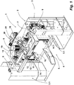
- a mixing machine 1 is used for industrial mixing of mixing material contained in a mixing container, for example plastic granules.
- the mixing machine 1 has a frame 2, which is provided in the illustrated embodiment by two stands 3, 3.1. Between the uprights 3, 3.1 is located in the area of the bottom of a container entrance 4.
- the container entrance 4 is laterally in the direction of the uprights 3, 3.1 limited by a respective side wall 5, 5.1.
- the two stands 3, 3.1 are connected to each other via a pivotable assembly 6.
- the pivotable assembly 6 comprises a frame member 7, on whose two narrow sides in each case a pivot shaft 8 is fixed.
- the pivot shaft 8 is mounted in the uprights 3, 3.1.
- In the stator 3 is an electric motor drive 9, with which the pivotable assembly 6 can be pivoted about the axis of its pivot shaft 8.
- the lifting devices 10, 10.1 have the same structure.
- the lifting device 10 is described by its basic structure. These statements apply equally to the lifting device 10.1.
- the lifting device 10 has a lifting plate 11 as part of a movable by a spindle 12 in the vertical direction Hubplattentician. On the lifting plate there is another plate which has a chamfer towards the container flange. This will center the container when lifted.
- the lifting plate unit is guided on a guide 13.
- the spindle 12 is driven by an electric motor. By means of the spindle 12, the Hubplattentician can be adjusted in the vertical direction. In FIG. 1 this is shown in its lowest position.
- Part of the Hubplatteniser is further a locking lever 14, which is about a vertical pivot axis from his in FIG. 1 shown basic position can be pivoted in the direction of mixing container recording.
- the pivoting of the locking lever 14 serves to lock a retracted into the container entrance 4 mixing container.
- the locking lever 4 acts against the outer wall of such a mixing container.
- the lifting device 10th is by means of an electric motor 15 as part of the pivotable assembly 6 in the direction of the longitudinal extent of the pivot axis of the pivotable assembly 6 movable.
- the electric motor 15 drives for this purpose in each case a spindle drive.
- the pivotable assembly further comprises a mixing head, of which in FIG. 1 its top (outside) is recognizable.
- the design of the mixing head 16 is in the front view of the mixing machine 1 of FIG. 2 recognizable.
- the mixing head 16 of the mixing machine 1 is designed as a lid for closing a mixing container open on the top side.
- the mixing head 16 includes a top plate 17. This will be described in more detail below with reference to FIGS FIGS. 3 to 5 described.
- Part of the mixing head 16 is one of the in FIG. 2 recognizable bottom of the top plate 17 spaced mixing tool 18, which is driven by an electric motor 19.
- the drive shaft of the electric motor 18 passes through the top plate 17th
- the arrangement of the mixing head 16 with respect to this supporting frame member 7 and the two lifting devices 10, 10.1 is from the bottom view of the pivotable assembly 6 of FIG. 3 recognizable.
- the mixing head 16 with the two lifting devices 10, 10.1 is gimballed within the frame member 7.
- the mixing head 16 can be pivoted with its two lifting devices 10, 10.1 about a transverse to the pivot axis of the frame member 7 axis of rotation.
- the mixing head 16 can be pivoted about two mutually perpendicular axes during operation of the mixing machine 1. This allows the implementation of a mixing process in which a mixing container connected to the mixing head 16 performs a multi-dimensional pendulum movement.
- the pivotable assembly relative to the frame is pivotable only on the previously described pivot shafts.
- the pivotable assembly is then not gimbaled, which is why in this embodiment, the present in the embodiment shown in the figures frame member is not present.
- the head plate 17 of the mixing machine 1 is a rotationally symmetric write (see FIG. 4 ), which is part of a head plate assembly 21.
- a cylindrical piece 22 is fixed, through which the drive shaft for driving the mixing tool 18 is guided.
- the drive shaft passes through the head plate 17 in its center, in which a drive shaft opening 23 is introduced for this purpose.
- opposing adapter shafts 24 attached on the lateral surface of the cylinder piece 22 . These serve to accommodate the mixing head 16 in the existing geometry.
- an opening 25 is also provided for a suction.
- the top plate 17 further carries a temperature sensor 26.
- the top plate 17 is, as shown in the sectional view of FIG. 5 recognizable as a flat plate performs.
- the outer edge region represents a connecting flange formed as an annular disc FIG. 5 the connection flange is designated by the reference numeral 27.
- the pointing away from the cylinder piece 22 top of the connecting flange 27 provides a contact surface for be connected to the mixing head 16 and its top plate 17 mixing container.
- three ring seals are integrated, as in the detailed view of FIG. 5 recognizable.
- Two seals are activatable ring seals 28, 28.1. These are arranged concentrically and at a distance from each other and surround the drive shaft opening 23 and thus the center axis of the top plate 17 concentrically.
- the activatable ring seals 28, 28.1 each have a circumferential hollow chamber 30 and a fluid port 31, with which they are connected to a compressed air source (not shown).
- the ring seals 28, 28.1 are inflatable and seated in a direction of the contact surface of the connecting flange 27 undercut groove 32. The protruding into the groove opening portion 33 of the ring seals 28 closes with its outer side 34 flush with the contact surface 35 of the Connection flange 27 from when the ring seal 28 is not activated.
- the lifting devices 10, 10.1 are adjustable in the radial direction to the top plate 17 by the above-described spindle drive.
- FIG. 6 shows in a perspective view, the lifting device 10.1.
- FIG. 1 described parts are identified therein by their reference numerals.
- Part of the pivotable assembly 6 is further a Einfahrbegrenzung, which is provided in the mixing machine 1 by a Einfahrbegrenzungsbauteil 36.
- the Einfahrbegrenzungsbauteil 36 is in a perspective view in FIG. 7 shown.
- FIG. 3 shows the arrangement of this component 36 with respect to the mixing head 16 and the two lifting devices 10, 10.1.
- the Einfahrbegrenzungsbauteil 36 has an adjustable in the radial direction to the center axis of the top plate 17 container stop 37, which is provided in the illustrated embodiment by three plate-like components with a vertical extension, which each have a narrow side in the direction of the container entrance 4.
- the retraction limit provided by the retraction limiting member 36 serves to adapt it to mixing containers different in diameter, which are to be connected to the mixing head 16 of the mixing machine 1 for the purpose of mixing a mixed material therein.
- FIG. 9 shown side view with removed side wall the structure of the Einfahrbegrenzungsbauteils 36 can be seen.
- the container stop 37 is adjustable by means of a pneumatic cylinder 38 in the radial direction.
- FIG. 8 shows the Einfahrbegrenzungsbauteil 36 with its container stopper 37 in that position in which this component is 36, when the largest possible diameter mixing container is to be connected to the mixing head 16 of the mixing machine 1 and for this purpose with its connection flange for sealing against the ring seal 28.1 acts.
- the container stopper 37 is connected by a piston rod 39 to the pneumatic cylinder 38.
- a piston rod 39 to the pneumatic cylinder 38.
- the locking pin 41 is in the transverse direction to the adjustment of the container stop 37, in FIG. 8 indicated by a block arrow, adjustable and protects the piston-cylinder unit for adjusting the container stop 37 before mixing container stops.
- FIG. 9 shows the Einfahrbegrenzungsbauteil 36 in an extended position in which its container stopper 37 is then when a mixing container is to be connected to the mixing head 16 of the mixing machine 1, the connecting flange acts against the inner ring seal 28, thus the diameter of this mixing container is smaller than the one whose connection flange acts to seal against the ring seal 28.1.
- the locking pin 41 is located to secure this position in a correspondingly different section of Arretierkulisse 40.
- the locking pin 41 is also controlled by a pneumatic cylinder so that it can be brought out of his engaging in a section of Arretierkulisse 41 position for adjustment of the container stop 37 ( not recognizable due to the perspective in the figures). In FIG. 8 this adjustment movement is indicated by an arrow arranged adjacent to the locking pin 41.
- FIG. 10 shows in its upper figure, the mixing machine M 1 when receiving a smaller diameter mixing container.
- the two lifting devices 10, 10.1 have in the in FIG. 10 Position shown above with their lifting plates 11 outwardly projecting annular flange 42 of the mixing container M 1 underrides.
- the mixing container M 1 has been retracted so far in the container entrance 4 for this purpose until a Wall outside 43 to the container stopper 37 in his in FIG. 9 position shown abuts.
- the locking lever 14 are in their locked position and also act against the wall outer side 43 of the mixing container M first By operating the lifting device 10, 10.1, the mixing container M 1 is lifted and moved with its connecting flange 42 against the top plate 17.
- connection flange 42 acts with its upper side against the annular seal 28, which is activated when the connection flange 42 of the mixing container M 1 is moved against the contact surface 35 of the connecting flange 27 of the top plate 17 of the mixing head 16.
- the pivotable assembly 6 is first pivoted in an overhead position.
- FIG. 11 Exemplary is in FIG. 11 the same sequence of figures shown as to FIG. 10 , However, the mixing container M 2 has a larger diameter than the mixing container M 1 . Accordingly, the Einfahrbegrenzungsbauteil 36 is in his in FIG. 8 shown position. Likewise, the lifting devices 10, 10. 1 are located in a position opposite to the position in FIG FIG. 10 radially further outward position.
- FIG. 12a shows a schematic representation of the connection of the connecting flange 42 of the mixing container M 1 to the connecting flange 27 of the top plate 17.
- the connecting flange 42 acts against the outside 34 of the ring seal 28, when activated.
- FIG. 12b shows the same section of the top plate 17 with the mixing container M 2 connected thereto, the connecting flange acts against the ring seal 28.1.
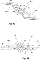
- a mixing tool 51 for an industrial mixing machine for mixing, for example, plastic granules in connection with the production of PCV is produced in the illustrated embodiment as a bent part made of stainless steel.
- the mixing tool 51 comprises a hub 52 with a shaft passage 53.
- the shaft passage 53 has two key spring receptacles 54, 54.1, which are at an angular distance of 90 degrees are arranged to each other.
- the tool shaft, on which the mixing tool 51 is to be mounted, has a feather key, so that the mixing tool 51 can be fixed in relation to the key of the tool shaft in two different positions on this.
- the hub 52 forms the central or central component of the mixing tool 51. Formed on the hub 52 are two mutually diametrically opposed to the axis of rotation mixing blades 55, 55.1.
- the mixing tool blades 55, 55.1 are constructed similarly, thus point-symmetrical to the axis of rotation D (s. FIG. 14 ).
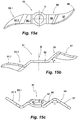
- the mixing blade 55 is described in more detail below. The same statements apply equally to the mixing blade 55.1.
- the mixing blade 55 includes a connecting portion 56 and a mixing blade portion 57.
- the connecting portion 56 is formed at an angle to the hub 52.
- the angle that the connecting portion 56 occupies with the plane of the hub 52 is typically between 30 to 45 degrees. In the illustrated embodiment, this angle ⁇ is 42 degrees (see also FIG. 15b ).
- the mixing blade portion 57 is angled relative to the plane of the connecting portion 56, along a bending line 59 (s. FIG. 14 ).
- the bending line 59 does not run transversely to the longitudinal extension of the mixing tool blade 55, but with a certain inclination, which in the illustrated embodiment is made at about 33 degrees with respect to a transverse bending line. In FIG. 14 this angle is indicated by ⁇ . Due to this orientation of the bending line 59, with which the mixing blade portion 57 is angled relative to the connecting portion 56, the mixing blade portion 57 is made relative to the plane of the hub 52, seen in the direction of rotation and in the radial direction. This causes a left-handed drive of the mixing tool 51, as in FIG.
- the plan view of the development of the mixing tool 51 in the FIG. 14 makes it clear that the mixing vanes 55, 55.1 with respect to a central longitudinal plane, the track in FIG. 14 indicated by the reference M, are executed asymmetrically.
- the in a left-handed drive of the mixing tool 51 facing in the direction of rotation end face is designed sickle-shaped in the illustrated embodiment in the region of the mixing blade section 57. This supports the energy input into the mix to be mixed.
- the sickle-shaped design of pointing in a left-handed drive in the direction of rotation end face of the mixing blade section 57 supports a Mischgut lacking of the mixing tool 51 enclosing wall of a mixing container directed away.
- the crescent-shaped portion of this end face of the mixing blade section 57 is designed as a cutting edge. Due to the employment of the mixing blade section 57, the upper edge of this end face in the direction of rotation, so that a certain cutting or homogenization effect is achieved by this.
- the asymmetrical design of the mixing blade section 57 is due to the fact that both end faces of the mixing blade section 57 are brought together in a mixing blade tip 60.
- the mixing blade tip 60 is located in the extension of the left-hand drive in the direction of rotation facing, just running, integrally formed on the hub 52 end face portion. Starting from the mixing blade tip 60 is the other end face rounded, wherein in the illustrated embodiment, a constant radius of curvature has been selected before this end goes into its straight, integrally formed on the hub 52 end face portion.
- the mixing blade portion 57 is angled with respect to the connecting portion 56 along the bending line 59 in the illustrated embodiment with an angle of 110 degrees (s. FIG. 15c ).
- FIGS. 15a-15c show different views of the mixing tool 51.
- FIG. 15a shows the mixing tool 51 in a plan view.
- FIG. 15b shows the mixing tool 51 in a side view of the hub 52.
- the employment of the mixing blade sections 57, 57.1 can be clearly seen. It can also be seen that the mixing blade sections 57, 57.1 are located in different planes with respect to the longitudinal extent of the axis of rotation D.
- FIG. 15c shows a side view of the end faces of the mixing blade sections 57, 57.1. Due to their employment, the hub 52 can be seen in a perspective view in this illustration of the mixing tool 51.
- the mixing machine 1 can be operated with a mixing tool 51, as described above, for mixing of mixed material.
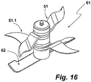
- the mixing time for a mixing process can be reduced if, instead of a single mixing tool 51, two mixing tools of this type are used, which then form a mixing tool set.
- a mixing tool set composed of two mixing tools 51, 51.1, is in FIG. 16 shown in a perspective view.
- both mixing tools 51, 51.1 are oriented in the same direction with respect to each other, but offset by 90 degrees on a tool shaft of a mixing machine not otherwise shown.
- Such an assembly is made possible by the two key spring receptacles 54, 54.1, which are introduced into the shaft passage 53 of the hub 52.
- the mixing tool set 61 of the embodiment of FIG. 15 is next to the two mixing tools 51, 51.1 still a soil clearing Tool 62 associated. This sits together with the two mixing tools 51, 51.1 on the same tool shaft.
- the soil clearing tool 62 is located in the immediate vicinity of the bottom of a mixing container, not shown in the figures.
- the soil-clearing tool 62 is inclined in the direction of rotation and serves the purpose of lifting in the region of the bottom of the mixing head 16 befindliches mix and feed the mixing tools 51, 51.1.
Landscapes
- Chemical & Material Sciences (AREA)
- Chemical Kinetics & Catalysis (AREA)
- Mixers Of The Rotary Stirring Type (AREA)
- Processing And Handling Of Plastics And Other Materials For Molding In General (AREA)
Abstract
Description
- Die Erfindung betrifft eine Mischmaschine, umfassend einen Mischkopf sowie zumindest ein Anschlussmittel zum Anschließen eines ein Mischgut enthaltenden, anschlussseitig offenen Mischcontainers an den Mischkopf zum Zwecke der Ausbildung eines geschlossenen Mischbehälters, welcher Mischkopf als Teil einer schwenkbaren Baugruppe schwenkbar gegenüber einem Gestell dergestalt gelagert ist, so dass der aus Mischkopf und Mischcontainer gebildete geschlossene Mischbehälter zum Durchführen des Mischprozesses gegenüber dem Gestell verschwenkbar ist, und welcher Mischkopf wenigstens ein rotatorisch angetriebenes Mischwerkzeug trägt.
- Bei derartigen Mischmaschinen handelt es sich um industrielle Mischer, die zum Mischen insbesondere von Schüttgut, typischerweise pulverförmigem Schüttgut, wie dieses etwa zum Erstellen von Kunststoffgranulatgemischen oder auch in der Farbindustrie benötigt wird, eingesetzt werden. Diese Mischmaschinen verfügen über einen gegenüber einem Gestell schwenkbaren Mischkopf, der gleichzeitig zum Verschließen eines das Mischgut enthaltenden Mischcontainers dient, der zum Zwecke des Mischens eines darin befindlichen Mischgutes an den Mischkopf angeschlossen wird. Nach Anschließen des Behältnisses an den Mischkopf ist aus dem Mischkopf und dem das Mischgut enthaltenen Mischcontainer ein geschlossener Mischbehälter gebildet. Zum Zwecke des Anschließens des Behältnisses an den Mischkopf verfügt der Mischkopf über Anschlussmittel. Hierbei handelt es sich unter anderem um einen in radialer Richtung nach außen abragenden umlaufenden Anschlussflansch, an den der komplementäre Anschlussflansch des Mischcontainers zur Anlage gebracht wird. Hierzu werden beispielsweise Spindelhübe eingesetzt, mit denen der Mischcontainer mit seinem Anschlussflansch gegen den Anschlussflansch des Mischkopfes unter Zwischenschaltung einer Dichtung gepresst wird. Aufgrund des Umstandes, dass bei diesen Mischmaschinen ein das Mischgut enthaltender Mischcontainer an den Mischkopf angeschlossen wird, werden diese Mischer auch als Containermischer angesprochen. Der Mischkopf selbst verfügt über eine konkav gekrümmte Bodenseite, die in eine umlaufende zylindrische Wand übergeht, die konzentrisch zur Zentrumsachse des Mischkopfes verläuft und an ihrem freien Ende den Anschlussflansch trägt. Der Mischkopf trägt zumindest ein Mischwerkzeug, dessen Antriebswelle durch den Boden des Mischkopfes hindurchgeführt ist.
- Der Mischkopf selbst ist schwenkbar gegenüber dem Maschinengestell der Mischmaschine angeordnet, damit das Mischen in Bezug auf den Mischkopf in einer Überkopfstellung, bei der der Mischkopf zuunterst und der daran angeschlossene Mischcontainer zuoberst angeordnet sind. Diese Überkopfstellung ist erforderlich, damit das in dem Mischcontainer enthaltene Mischgut in Kontakt mit dem zumindest einen von dem Mischkopf getragenen Mischwerkzeug kommt. Das rotatorisch angetriebene Mischwerkzeug dient zum Erzeugen eines Mischgutstromes innerhalb des geschlossenen Mischraumes. Ein solcher industrieller Mischer ist beispielsweise aus
EP 0 225 495 A2 bekannt. - Da bei derartigen Mischmaschinen das geschlossene Mischbehältnis durch Verschließen des offenen Mischcontainers mit dem Mischkopf bereitgestellt wird, sind diese Teile bezüglich der Auslegung der zusammenwirkenden Anschlussflansche aufeinander abgestimmt. Dieses bedeutet, dass an einem Mischkopf nur Mischcontainer mit ein und derselben Anschlussgeometrie angeschlossen werden können. Um das gewünschte Mischergebnis zu erzielen, ist es erforderlich, dass der Mischcontainer einen gewissen Mindestfüllstand an dem zu mischenden Mischgut enthält. Oftmals sind jedoch von der Menge des zu mischenden Mischgutes unterschiedliche Chargen zu mischen. Zu diesem Zweck werden bezüglich ihrer Größe Mischcontainer mit einem unterschiedlichen Fassungsvolumen bereitgestellt. Diese unterschiedlich großen Mischcontainer haben jeweils eine unterschiedliche Anschlussgeometrie, insbesondere einen unterschiedlichen Durchmesser ihres Anschlussflansches. Wenn in einem derartige Mischer einsetzenden Betrieb Mischcontainer unterschiedlicher Größe verwendet werden, müssen auch Mischmaschinen vorhanden sein, die bezüglich der Anschlussgeometrie ihrer Mischköpfe an die Anschlussgeometrie der unterschiedlichen Mischcontainer angepasst sind. Entsprechend hoch sind die Investitionskosten, wenn Mischcontainer mit unterschiedlichem Fassungsvermögen und somit mit unterschiedlicher Anschlussgeometrien benötigt werden, damit das darin enthaltene Mischgut mit einer derartigen Mischmaschine gemischt werden kann.
- Ausgehend von diesem diskutierten Stand der Technik liegt der Erfindung daher die Aufgabe zu Grunde, eine Mischmaschine der eingangs genannten Art dergestalt auszubilden, dass an deren Mischkopf Mischcontainer mit unterschiedlichen Durchmessern ihrer Anschlussflansche, mithin Mischcontainer mit einem unterschiedlichen Fassungsvolumen anschließbar sind.
- Gelöst wird diese Aufgabe erfindungsgemäß durch eine eingangs genannte, gattungsgemäße Mischmaschine, bei der der Mischkopf eine Kopfplatte mit einem daran angeformten, als Ringscheibe ausgebildeten Anschlussflansch mit einer ebenen Anlagefläche aufweist, in welcher Anlagefläche des Anschlussflansches zumindest zwei Ringdichtungen unterschiedlichen Durchmessers unter Belassung eines Abstandes zueinander angeordnet sind, so dass an den Mischkopf Mischcontainer mit unterschiedlichen Anschlussdurchmessern ihrer Mischkopfanschlussseite anschließbar sind, und dass das zumindest eine Anschlussmittel zum Ergreifen von im Durchmesser ihrer Anschlussseite unterschiedlicher Mischcontainer ausgelegt ist.
- Bei dieser Mischmaschine ist der mischkopfseitige Anschlussflansch als Ringscheibe mit einer Breite ausgeführt, dass in dessen Anlagefläche zumindest zwei Ringdichtungen unterschiedlichen Durchmessers angeordnet sind. Diese Ringdichtungen sind voneinander beabstandet. Der Durchmesser jeder Ringdichtung ist an den Durchmesser des Anschlagflansches eines bezüglich seiner Anschlussgeometrie unterschiedlichen Mischcontainers angepasst. Somit können an den Mischkopf einer solchen Mischmaschine von im Durchmesser ihrer Anschlussseite unterschiedlich große Mischcontainer angeschlossen werden. Wenn in dem Anschlussflansch des Mischkopfes zwei unterschiedlich große Ringdichtungen angeordnet sind, können an diesen Mischkopf zwei im Durchmesser ihrer Anschlussseite unterschiedlich ausgelegte Mischcontainer angeschlossen werden. Durchaus können in dem mischkopfseitigen Anschlussflansch auch drei oder mehrere Ringdichtungen angeordnet sein. Auch wenn zum Mischen des Mischgutes in unterschiedlich großen Mischcontainern ein und dasselbe Mischwerkzeug verwendet werden kann, kann es durchaus sinnvoll sein, wenn der Durchmesserunterschied zu groß ist, den Mischvorgang in einem bezüglich seiner Anschlussgeometrie größeren Mischcontainer mit einem anderen Mischwerkzeug durchzuführen als beim Mischen des Mischgutes, dessen anschlussseitiger Durchmesser kleiner ist.
- Das wenigstens eine Anschlussmittel zum Anschließen des Mischcontainers an den Mischkopf ist ausgelegt, damit mit diesem im Durchmesser unterschiedlich große Mischcontainer erfasst und an den Mischkopf angeschlossen werden können. Somit kann mit ein und derselben Mischmaschine Mischgut, dass in unterschiedlich großen Mischcontainern enthalten ist, gemischt werden, wobei der Mischprozess in der bewährten Überkopfstellung mit dem Mischkopf zuunterst und dem mit seiner Öffnung zum Mischkopf weisenden Seite des Mischcontainers zuoberst durchgeführt wird. Der Mischprozess kann auf Grund der schwenkbaren Aufhängung des Mischkopfes am Gestell durch eine Pendelbewegung unterstützt werden.
- Die Ringdichtungen sind typischerweise konzentrisch zueinander angeordnet und sind ebenfalls konzentrisch zu der den Boden des Mischkopfes durchgreifenden, zumindest ein Mischwerkzeug tragenden Antriebswelle angeordnet. Durchaus möglich ist auch eine Ausgestaltung des Mischkopfes einer solchen Mischmaschine, bei der das Mischwerkzeug außermittig bezüglich des Bodens des Mischkopfes angeordnet ist, wobei bei einer solchen Ausgestaltung die Ringdichtungen dann konzentrisch zur Zentrumsachse des Bodens in die Anschlussfläche des Anschlussflansches integriert sind.
- Gemäß einem Ausführungsbeispiel verfügt der Mischkopf über eine Kopfplatte, die insgesamt eine über die Fläche durchgehende ebene Bodenseite aufweist. Bei einer solchen Ausgestaltung geht somit die Innenseite des Mischkopfes in den Anschlussflansch über. Bei einer solchen Auslegung des Mischkopfes ist die Kopfplatte vorzugsweise eine Platte, bei der die Außenseite ebenfalls eben ist und parallel zur inneren Bodenseite verläuft.
- Als Ringdichtungen können aktivierbare und/oder nicht aktivierbare Dichtungen eingesetzt werden. Auch eine Kombination derartiger Ringdichtungen ist möglich. Aktivierbare Dichtungen sind solche Dichtungen, die eine umlaufende Hohlkammer aufweisen und die sich bei Einbringen eines Fluides in die Hohlkammer, beispielsweise Druckluft aufblähen und sodann entsprechend dem in die umlaufende Hohlkammer eingebrachten Druck gegen den Anschlussflansch des Mischcontainers wirken. Zu diesem Zweck weisen diese Hohlkammern einen Fluidanschluss auf, durch den das für die Aktivierung verwendete Fluid eingebracht wird. Bei pneumatisch aktivierbaren Ringdichtungen ist der Fluidanschluss an eine Druckluftquelle angeschlossen. Derartige aktivierbare Ringdichtungen haben zum Vorteil, dass die Dichtfläche bei Nichtbenutzung bündig mit der Ebene der Anschlussfläche des Anschlussflansches des Mischkopfes abschließen kann, um Materialansammlungen zu verhindern. Zudem besteht die Möglichkeit, dass beim Reinigen des Mischkopfes die Ringdichtung durch ihre Aktivierung bewegt und somit unter Umständen darauf anhaftendes Material abplatzen kann, wodurch der Reinigungsprozess erleichtert wird.
- Als Anschlussmittel zum Anschließen eines Mischcontainers an die Kopfplatte des Mischkopfes kann eine solche Mischmaschine zwei einander zur Zentrumsachse der Kopfplatte diametral gegenüberliegende Hubeinrichtungen aufweisen, die ebenfalls Bestandteil der schwenkbaren Baugruppe sind. Diese Hubeinrichtungen sind an der schwenkbaren Baugruppe in radialer Richtung verstellbar, beispielsweise elektromotorisch durch jeweils einen Spindeltrieb. Jede dieser Hubeinrichtungen verfügt über eine Hubplatte zum Untergreifen des in radialer Richtung abragenden Anschlussflansches eines an den Mischkopf anzuschließenden Mischcontainers. Durch Untergreifen des Anschlussflansches des Mischcontainers mit der Hubplatte und Anheben desselben mit den Hubeinrichtungen wird ein Mischcontainer zur Anlage an die Anlagefläche des Anschlussflansches der Kopfplatte gebracht. Zusätzlich kann jede Hubeinrichtung benachbart zu ihrer Hubplatte einen schwenkbaren Arretierhebel aufweisen, die, wenn in ihrer Arretierstellung befindlich, gegen die Außenwand eines von der Hubplatte gehaltenen Mischcontainers wirken. Derartige Arretierhebel sichern die Containerstellung.
- Eine Einfahrbegrenzung ist zweckmäßigerweise ebenfalls an die schwenkbare Baugruppe der Mischmaschine angeschlossen. Diese dient dem Zweck, die Einfahrbewegung eines Mischcontainers zu begrenzen, so dass dieser an einer Position zum Stehen kommt, in der sein Anschlussflansch mit der in die Kopfplatte des Mischkopfes integrierten Ringdichtung, mit der die Abdichtung zwischen dem Anschlussflansch des Mischcontainers und der Kopfplatte erfolgt, fluchtet. Die Einfahrbegrenzung ist ebenso wie die Hubeinrichtungen in radialer Richtung zur Zentrumsachse der Kopfplatte des Mischkopfes verstellbar, damit bei im Durchmesser unterschiedlichen Containern die Einfahrbegrenzung an die richtige Stelle positioniert werden kann. Insofern wirkt bei dieser Ausgestaltung die Einfahrbegrenzung nicht gegenüber einem Rollen tragenden Untergestell des Mischcontainers, sondern gegen die Mischcontainerwandung. Konkret kann die Einfahrbegrenzung durch einen entsprechend verstellbaren Containeranschlag ausgeführt sein. Zum Schutze des Containeranschlagantriebes, beispielsweise einer pneumatisch aktivierbaren Kolben-Zylinder-Anordnung kann ein Arretierungsbolzen vorgesehen sein, durch den der Containeranschlag vorgesehenen Stellungen gesichert ist, wobei der Arretierungsbolzen in Querrichtung zur Verstellrichtung des Containeranschlages verstellbar ist. Anprallbewegungen durch den Mischcontainer werden dann nicht in die Kolben-Zylinder-Anordnung eingeleitet.
- Für die Verstellung der Arretierhebel der Hubeinrichtungen, des Containeranschlages sowie des Arretierungsbolzens werden gemäß einer Ausgestaltung pneumatische Stelleinrichtungen eingesetzt.
- Auch wenn grundsätzlich bei einem Anschluss von im Durchmesser unterschiedlicher Mischcontainer an den Mischkopf in Abhängigkeit von der Größe des Mischbehälters, das heißt: seines Durchmessers, jeweils an den Durchmesser des Mischcontainers angepasste Mischwerkzeuge auf der Antriebswelle montiert werden können, ist in einem bevorzugten Ausführungsbeispiel vorgesehen, dass der Mischkopf ein Mischwerkzeug trägt, mit dem der gewünschte Mischthrombos ausgebildet werden kann, und zwar weitgehend unabhängig von der radialen Beabstandung der Mischcontainerseitenwand von dem äußeren Abschluss der Flügel des Mischwerkzeuges. Bei einer solchen Ausgestaltung ist an die Antriebswelle ein Mischwerkzeug angeschlossen, welches bezüglich seiner Größe an die Größe des im Durchmesser kleinsten, an den Mischkopf anschließbaren Mischcontainers ausgelegt ist. Ein Betrieb der Mischmaschine mit einem im Durchmesser größeren Mischcontainer kann dann ohne Werkzeugwechsel vorgenommen werden.
- Ein solches, bezüglich der anzuschließenden Mischcontainergröße auch als Universalmischwerkzeug anzusprechendes Mischwerkzeug verfügt über zumindest zwei gleichartige, an eine Nabe, mit der das Mischwerkzeug an die Antriebswelle angeschlossen ist, Mischwerkzeugflügel. Die Mischwerkzeugflügel weisen jeweils einen gegenüber der Ebene der Nabe in jeweils bezüglich der Längserstreckung der Drehachse entgegengesetzte Richtungen abgewinkelten Verbindungsabschnitt auf, an dem jeweils ein sich in radialer Richtung von der Nabe weg erstreckender, gegenüber der Ebene der Nabe in zwei Richtungen angestellter Mischflügelabschnitt angeformt ist. Ein solches Mischwerkzeug ist nicht nur ausgelegt, Energie in das Mischwerkzeug einzubringen, sondern auch um das Mischgut zwar in axialer Richtung von dem Mischwerkzeug weg, jedoch auch mit einem in Richtung zur Drehachse hin gerichteten Bewegungsmoment zu beaufschlagen. Durch die mit einem solchen Mischwerkzeug aufgrund der Anstellung seiner Mischwerkzeugflügel in das Mischwerkzeug eingebrachten Energie wird der Mischprozess intensiviert, sodass eine Vermischung nicht ausschließlich auf die Ausbildung eines Mischthrombos, wie dieses bei anderen Mischwerkzeugen der Fall ist, ankommt.
- Bei einem solchen Mischwerkzeug wird die Energie in das Mischgut in prinzipiell zwei Höhenbereichen in das Mischgut eingebracht, welche Höhenbereiche in Richtung der Erstreckung der Drehachse voneinander beabstandet sind. Erreicht wird dieses durch Vorsehen von jeweils einem Verbindungsabschnitt in jedem Mischwerkzeugflügel, der die Nabe des Mischwerkzeuges mit einem Mischflügelabschnitt verbindet. Die eigentliche Mischarbeit wird von den Mischflügelabschnitten vorgenommen, auch wenn dem Verbindungsabschnitt je nach Auslegung auch eine Misch- und/oder Energieeintragsfunktionalität zukommen kann. Die Mischflügelabschnitte erstrecken sich von dem Verbindungsabschnitt in radialer Richtung nach außen, wobei diese eine sichelartige Krümmung in radialer Richtung aufweisen können. Die Mischflügelabschnitte selbst können eben ausgeführt sein. Denkbar ist auch eine gekrümmte Ausgestaltung. Bei einer gekrümmten Ausgestaltung können die Mischflügelabschnitte in den jeweiligen Verbindungsabschnitt übergehen. Anderenfalls sind die Mischflügelabschnitte winklig an den jeweiligen Verbindungsabschnitt angeformt. Bemerkenswert bei diesem Mischwerkzeug ist die Anstellung der Mischflügelabschnitte in Bezug auf die Ebene der Nabe. Angestellt sind die Mischflügelabschnitte gegenüber der Ebene der Nabe, bei welcher Ebene es sich um die zur Drehachse querverlaufende Ebene handelt, in zwei Richtungen dieser Ebene, und zwar in Rotationsrichtung und in radialer Richtung zur Drehachse hin. Somit nehmen die Mischflügelabschnitte eine in Rotationsrichtung sowie in radialer Richtung geneigte Raumlage ein. Der Anstellungswinkel der Mischflügelabschnitte kann in beide Richtungen unterschiedlich oder auch gleich sein. Ein typischer Anstellungswinkel kann mit 10 bis 15 Grad angegeben werden. Den Anstellungswinkel wird man in Abhängigkeit von dem zu mischenden Material und der vorgesehenen Rotationsgeschwindigkeit wählen, da in Abhängigkeit von dem Anstellungswinkel mehr oder weniger Energie bei einer Rotation des Mischwerkzeuges in das Mischgut eingebracht wird. Bei einem rotierenden Antrieb eines solchen Mischwerkzeuges wird durch die Anstellung der Mischflügelabschnitte ein der Neigung entsprechendes Moment in die Mischgutpartikel eingebracht, wobei das Bewegungsmoment einen der Neigung entsprechenden vektoriellen Anteil in axialer Richtung von dem Mischwerkzeug weg hat.
- Gemäß einem Ausführungsbeispiel eines solchen Mischwerkzeuges sind die in die eine und die andere Rotationsrichtung weisenden Stirnseiten der Mischwerkzeugflügel in Bezug auf eine den Mischflügelabschnitt schneidende Mittellängsebene zu dieser asymmetrisch ausgeführt. Diese unterschiedliche Kontur an den beiden Stirnseiten eines Mischflügelabschnittes erlaubt ebenfalls eine Einflussnahme auf den Energieeintrag. Aufgrund der asymmetrischen Auslegung der Mischflügelabschnitte ist der Energieeintrag in das Mischgut bei einem rotierenden Antrieb des Mischwerkzeuges in die eine Richtung anders als in die andere Richtung.
- Unabhängig davon, ob in einer Draufsicht die Mischflügelabschnitte bezüglich der genannten Mittelängsebene asymmetrisch zueinander ausgeführt sind oder nicht, kann die in die eine Drehrichtung weisende Stirnseite oder ein Abschnitt davon als Schneide ausgeführt sein, während die andere Stirnseite stumpf ist. Wird ein solches Mischwerkzeug mit seiner Schneide in Drehrichtung weisend betrieben, wird durch den Betrieb des Mischwerkzeuges das Mischgut zudem homogenisiert. Durch einen alternierenden Drehbetrieb des Mischwerkzeuges innerhalb eines Mischbehältnisses einer Mischmaschine sowie eine Änderung der Drehzahl kann der Mischprozess gesteuert und an die Eigenschaften des zu mischenden Mischgutes besonders gut angepasst werden.
- Die Erfindung ist nachfolgend anhand eines Ausführungsbeispiels unter Bezugnahme auf die beigefügten Figuren beschrieben:
- Fig. 1:
- Eine perspektivische Ansicht einer industriellen Mischmaschine,
- Fig. 2:
- eine Frontseitenansicht der Mischmaschine der
Figur 1 , - Fig. 3:
- eine Schnittdarstellung mit einer Unteransicht der verschwenkbaren Baugruppe der Mischmaschine entlang der Linie B-B der
Figur 2 , - Fig. 4:
- eine perspektivische Alleindarstellung der Kopfplatte des Mischkopfes als Teil einer Kopfplattenbaugruppe,
- Fig. 5:
- ein Schnitt durch die Kopfplattenbaugruppe der
Figur 4 , - Fig. 6:
- eine perspektivische Ansicht einer der beiden Hubeinrichtungen der Mischmaschine der
Figur 1 , - Fig. 7:
- in einer Alleindarstellung ein Einfahrbegrenzungsbauteil der Mischmaschine der vorstehenden Figuren in einer perspektivischen Ansicht,
- Fig. 8:
- das Einfahrbegrenzungsbauteil der
Figur 7 in einer Seitenansicht in einer ersten Stellung, - Fig. 9:
- das Einfahrbegrenzungsbauteil der
Figuren 7 und 8 in einer zweiten Stellung, - Fig. 10:
- zwei Frontansichten der Mischmaschine mit einem in seine Containeraufnahme eingefahrenen Mischcontainer einer ersten Mischcontainergröße (oben) und mit dem durch die Hubeinrichtungen angehobenen und an den Mischkopf angeschlossenen Mischcontainer (unten),
- Fig. 11:
- zwei Frontansichten der Mischmaschine mit einem in seine Containeraufnahme eingefahrenen Mischcontainer einer zweiten Mischcontainergröße (oben) und mit dem durch die Hubeinrichtungen angehobenen und an den Mischkopf angeschlossenen Mischcontainer (unten),
- Fig. 12a, 12b:
- eine Ausschnittsdarstellung der Kopfplatte des Mischkopfes der Mischmaschine der vorbeschriebenen Figuren mit dem daran angeschlossenen Anschlussflansch eines Mischcontainers erster Größe (
Figur 12a ) und mit einem daran angeschlossenen Mischcontainer zweiter Größe (Figur 12b), - Fig. 13:
- eine perspektivische Ansicht eines Mischwerkzeuges für die vorbeschriebene Mischmaschine,
- Fig. 14:
- eine Draufsicht auf eine Abwicklung des Mischwerkzeuges der
Figur 13 , - Fig. 15a - 15c:
- verschiedene Ansichten des Mischwerkzeuges der
Figur 13 und - Fig. 16:
- ein Mischwerkzeugsatz mit zwei Mischwerkzeugen der Figuren 13 bis 15 in einer ersten Anordnung der beiden Mischwerkzeuge zueinander und mit einem bodenräumenden Werkzeug.
- Eine Mischmaschine 1 dient zum industriellen Mischen von in einem Mischcontainer befindlichem Mischgut, beispielsweise Kunststoffgranulaten. Die Mischmaschine 1 verfügt über ein Gestell 2, welches bei dem dargestellten Ausführungsbeispiel durch zwei Ständer 3, 3.1 bereitgestellt ist. Zwischen den Ständern 3, 3.1 befindet sich im Bereich des Bodens eine Containereinfahrt 4. Die Containereinfahrt 4 ist seitlich in Richtung zu den Ständern 3, 3.1 durch jeweils eine Seitenwand 5, 5.1 begrenzt. In ihrem oberen Abschnitt sind die beiden Ständer 3, 3.1 über eine schwenkbare Baugruppe 6 miteinander verbunden. Die schwenkbare Baugruppe 6 umfasst ein Rahmenbauteil 7, an dessen beide Schmalseiten jeweils eine Schwenkwelle 8 befestigt ist. Die Schwenkwelle 8 ist in den Ständern 3, 3.1 gelagert. In dem Ständer 3 befindet sich ein elektromotorischer Antrieb 9, mit dem die schwenkbare Baugruppe 6 um die Achse ihrer Schwenkwelle 8 verschwenkt werden kann.
- Teil der schwenkbaren Baugruppe 6 sind zwei als Spindelhübe ausgeführte Hubeinrichtungen 10, 10.1. Die Hubeinrichtungen 10, 10.1 sind gleich aufgebaut. Nachfolgend ist die Hubeinrichtung 10 von ihrem prinzipiellen Aufbau her beschrieben. Diese Ausführungen gelten gleichermaßen für die Hubeinrichtung 10.1. Die Hubeinrichtung 10 verfügt über eine Hubplatte 11 als Teil einer durch eine Spindel 12 in vertikaler Richtung verfahrbaren Hubplatteneinheit. Auf der Hubplatte befindet sich eine weitere Platte, die zum Containerflansch hin eine Fase besitzt. Dadurch wird der Container beim Anheben zentriert. Die Hubplatteneinheit ist an einer Führung 13 geführt. Angetrieben ist die Spindel 12 durch einen Elektromotor. Mittels der Spindel 12 kann die Hubplatteneinheit in vertikaler Richtung verstellt werden. In
Figur 1 ist diese in ihrer untersten Position gezeigt. Teil der Hubplatteneinheit ist des Weiteren ein Arretierungshebel 14, der um eine vertikale Schwenkachse aus seiner inFigur 1 gezeigten Grundstellung in Richtung der Mischcontaineraufnahme verschwenkt werden kann. Die Verschwenkung des Arretierhebels 14 dient zum Verriegeln eines in die Containereinfahrt 4 eingefahrenen Mischcontainers. Der Arretierungshebel 4 wirkt gegen die Außenwandung eines solchen Mischcontainers. Die Hubeinrichtung 10 ist mittels eines Elektromotors 15 als Teil der schwenkbaren Baugruppe 6 in Richtung der Längserstreckung der Schwenkachse der schwenkbaren Baugruppe 6 verfahrbar. Der Elektromotor 15 treibt zu diesem Zweck jeweils einen Spindelantrieb an. - Die schwenkbare Baugruppe umfasst des Weiteren einen Mischkopf, von dem in
Figur 1 seine Oberseite (Außenseite) erkennbar ist. - Die Ausbildung des Mischkopfes 16 ist in der Frontansicht der Mischmaschine 1 der
Figur 2 erkennbar. Der Mischkopf 16 der Mischmaschine 1 ist als Deckel zum Verschließen eines oberseitig offenen Mischcontainers ausgelegt. Der Mischkopf 16 umfasst eine Kopfplatte 17. Diese ist nachstehend detaillierter unter Bezugnahme auf dieFiguren 3 bis 5 beschrieben. Teil des Mischkopfes 16 ist ein von der inFigur 2 erkennbaren Unterseite der Kopfplatte 17 beabstandetes Mischwerkzeug 18, welches durch einen Elektromotor 19 angetrieben ist. Die Antriebswelle des Elektromotors 18 durchgreift die Kopfplatte 17. - Die Anordnung des Mischkopfes 16 bezüglich des diesen tragenden Rahmenbauteils 7 und den beiden Hubeinrichtungen 10, 10.1 ist aus der Unteransicht der schwenkbaren Baugruppe 6 der
Figur 3 erkennbar. Der Mischkopf 16 mit den beiden Hubeinrichtungen 10, 10.1 ist innerhalb des Rahmenbauteils 7 kardanisch aufgehängt. Mittels eines Schwenkantriebes 20 kann der Mischkopf 16 mit seinen beiden Hubeinrichtungen 10, 10.1 um eine quer zur Schwenkachse des Rahmenbauteils 7 verlaufende Drehachse verschwenkt werden. Infolge dessen kann der Mischkopf 16 um zwei rechtwinklig zueinander stehende Achsen bei einem Betrieb der Mischmaschine 1 verschwenkt werden. Dieses erlaubt die Durchführung eines Mischprozesses, bei dem ein an den Mischkopf 16 angeschlossener Mischcontainer eine mehrdimensionale Pendelbewegung ausführt. - In einem in den Figuren nicht dargestellten Ausführungsbeispiel ist die schwenkbare Baugruppe gegenüber dem Gestell nur über die bereits zuvor beschriebenen Schwenkwellen verschwenkbar. Bei dieser Ausgestaltung ist die schwenkbare Baugruppe sodann nicht kardanisch aufgehängt, weshalb bei dieser Ausgestaltung auch das in dem in den Figuren gezeigten Ausführungsbeispiel vorhandene Rahmenbauteil nicht vorhanden ist.
- Die Kopfplatte 17 der Mischmaschine 1 ist eine rotationssymmetrische Schreibe (siehe
Figur 4 ), die Teil einer Kopfplattenbaugruppe 21 ist. An die Außenseite der Kopfplatte 17 ist ein Zylinderstück 22 befestigt, durch das die Antriebswelle zum Antreiben des Mischwerkzeuges 18 geführt ist. Die Antriebswelle durchgreift die Kopfplatte 17 in ihrem Zentrum, in die zu diesem Zweck eine Antriebswellendurchbrechung 23 eingebracht ist. An die Mantelfläche des Zylinderstücks 22 sind, wie ausFigur 4 erkennbar, einander gegenüberliegende Adapterwellen 24 befestigt. Diese dienen zum Aufnehmen des Mischkopfes 16 in der vorhandenen Geometrie. In die Kopfplatte 17 ist ferner eine Öffnung 25 für eine Absaugung vorgesehen. Die Kopfplatte 17 trägt des Weiteren einen Temperatursensor 26. - Die Kopfplatte 17 ist, wie aus der Schnittdarstellung der
Figur 5 erkennbar als ebene Platte ausführt. Der äußere Randbereich stellt einen als Ringscheibe ausgebildeten Anschlussflansch dar. InFigur 5 ist der Anschlussflansch mit dem Bezugszeichen 27 gekennzeichnet. Die von dem Zylinderstück 22 wegweisende Oberseite des Anschlussflansches 27 stellt eine Anlagefläche für an den Mischkopf 16 bzw. seiner Kopfplatte 17 anzuschließende Mischcontainer dar. In die Anlagefläche des Anschlussflansches 27 sind drei Ringdichtungen integriert, wie in der Detailansicht derFigur 5 erkennbar. Bei zwei Dichtungen handelt es sich um aktivierbare Ringdichtungen 28, 28.1. Diese sind konzentrisch und mit Abstand zueinander angeordnet und umgeben die Antriebswellendurchbrechung 23 und somit die Zentrumsachse der Kopfplatte 17 konzentrisch. Zwischen diesen beiden aktivierbaren Ringdichtungen 28, 28.1 befindet sich eine weitere Ringdichtung 29, die nicht aktivierbar ist. Die aktivierbaren Ringdichtungen 28, 28.1 verfügen jeweils über eine umlaufende Hohlkammer 30 und einen Fluidanschluss 31, mit dem diese an eine Druckluftquelle angeschlossen sind (nicht dargestellt). Die Ringdichtungen 28, 28.1 sind aufblasbar und sitzen in einer aus Richtung der Anlagefläche des Anschlussflansches 27 hinterschnittenen Nut 32. Der in die Nutöffnung einragende Teil 33 der Ringdichtungen 28 schließt mit seiner Außenseite 34 bündig mit der Anlagefläche 35 des Anschlussflansches 27 ab, wenn die Ringdichtung 28 nicht aktiviert ist. Ist diese durch Einbringen von Druckluft in ihre umlaufende Hohlkammer 30 aufgeblasen und damit aktiviert, tritt die Außenseite 34, wenn kein Widerlager an der Außenseite 34 der Ringdichtung 28 anliegt, aus der umlaufenden Nutöffnung etwas heraus. Die vorstehende Erläuterung erfolgt anhand der Ringdichtung 28, zu der auch die entsprechenden Bezugszeichen in den Figuren enthalten sind. Der Übersicht halber sind diese Merkmale zu der Ringdichtung 28.1 in den Figuren nicht gezeigt. - In Folge der radialen Beabstandung der Ringdichtungen 28, 29, 28.1 können an die Kopfplatte 17 des Mischkopfes 16 Mischcontainer mit unterschiedlichem Durchmesser ihres anschlussseitigen Anschlussflansches und damit ihrer Anschlussseite angeschlossen werden. Aus diesem Grunde sind die Hubeinrichtungen 10, 10.1 in radialer Richtung zur Kopfplatte 17 durch den vorbeschriebenen Spindeltrieb verstellbar.
-
Figur 6 zeigt in einer perspektivischen Darstellung die Hubeinrichtung 10.1. Die bereits zuFigur 1 beschriebenen Teile sind darin mit ihren Bezugszeichen kenntlich gemacht. - Teil der schwenkbaren Baugruppe 6 ist ferner eine Einfahrbegrenzung, die bei der Mischmaschine 1 durch ein Einfahrbegrenzungsbauteil 36 bereitgestellt ist. Das Einfahrbegrenzungsbauteil 36 ist in einer perspektivischen Ansicht in
Figur 7 gezeigt.Figur 3 zeigt die Anordnung dieses Bauteils 36 in Bezug auf den Mischkopf 16 und die beiden Hubeinrichtungen 10, 10.1. Das Einfahrbegrenzungsbauteil 36 verfügt über einen in radialer Richtung zur Zentrumsachse der Kopfplatte 17 verstellbaren Containeranschlag 37, der bei dem dargestellten Ausführungsbeispiel durch drei plattenartige Bauteile mit einer vertikalen Erstreckung bereitgestellt ist, wobei diese mit jeweils einer Schmalseite in Richtung zu der Containereinfahrt 4 weisen. Die durch das Einfahrbegrenzungsbauteil 36 bereitgestellte Einfahrbegrenzung dient zum Anpassen derselben an im Durchmesser unterschiedliche Mischcontainer, die an den Mischkopf 16 der Mischmaschine 1 zum Zwecke des Mischens eines darin befindlichen Mischgutes angeschlossen werden sollen. In der inFigur 9 gezeigten Seitenansicht mit abgenommener Seitenwand ist der Aufbau des Einfahrbegrenzungsbauteils 36 erkennbar. Der Containeranschlag 37 ist mittels eines Pneumatikzylinders 38 in radialer Richtung verstellbar.Figur 8 zeigt das Einfahrbegrenzungsbauteil 36 mit seinem Containeranschlag 37 in derjenigen Stellung, in der sich dieses Bauteil 36 befindet, wenn der im Durchmesser größte mögliche Mischcontainer an den Mischkopf 16 der Mischmaschine 1 angeschlossen werden soll und zu diesem Zweck mit seinem Anschlussflansch zur Abdichtung gegen die Ringdichtung 28.1 wirkt. Der Containeranschlag 37 ist durch eine Kolbenstange 39 mit den Pneumatikzylinder 38 verbunden. Zur Sicherung der inFigur 8 gezeigten Position dient ein in eine Arretierkulisse 40 eingreifender Arretierungsbolzen 41. Der Arretierungsbolzen 41 ist in Querrichtung zur Verstellrichtung des Containeranschlages 37, inFigur 8 durch einen Blockpfeil kenntlich gemacht, verstellbar und schützt die Kolben-Zylinder-Einheit zum Verstellen des Containeranschlages 37 vor Mischcontaineranschlägen. -
Figur 9 zeigt das Einfahrbegrenzungsbauteil 36 in einer ausgefahrenen Stellung, in der sich sein Containeranschlag 37 dann befindet, wenn an den Mischkopf 16 der Mischmaschine 1 ein Mischcontainer angeschlossen werden soll, dessen Anschlussflansch gegen die innenliegende Ringdichtung 28 wirkt, mithin der Durchmesser dieses Mischcontainers kleiner ist als derjenige, dessen Anschlussflansch zum Abdichten gegen die Ringdichtung 28.1 wirkt. Der Arretierbolzen 41 befindet sich zur Sicherung dieser Position in einem entsprechend anderen Ausschnitt der Arretierkulisse 40. Der Arretierungsbolzen 41 ist ebenfalls durch einen Pneumatikzylinder ansteuerbar, damit dieser aus seiner in einen Ausschnitt der Arretierkulisse 41 eingreifenden Stellung für eine Verstellung des Containeranschlages 37 herausgebracht werden kann (auf Grund der Perspektive in den Figuren nicht erkennbar). InFigur 8 ist diese Verstellbewegung durch einen benachbart zu dem Arretierungsbolzen 41 angeordneten Pfeil kenntlich gemacht. -
Figur 10 zeigt in seiner oberen Abbildung die Mischmaschine M1 bei der Aufnahme eines im Durchmesser kleineren Mischcontainers. Die beiden Hubeinrichtungen 10, 10.1 haben in der inFigur 10 oben gezeigten Stellung mit ihren Hubplatten 11 den nach außen abragenden Ringflansch 42 des Mischcontainers M1 Untergriffen. Der Mischcontainer M1 ist zu diesem Zweck soweit in die Containereinfahrt 4 eingefahren worden, bis eine Wandaußenseite 43 an dem Containeranschlag 37 in seiner inFigur 9 gezeigten Stellung anschlägt. Die Arretierhebel 14 befinden sich in ihrer Arretierstellung und wirken ebenfalls gegen die Wandaußenseite 43 des Mischcontainers M1. Durch Betätigen der Hubeinrichtung 10, 10.1 wird der Mischcontainer M1 angehoben und mit seinem Anschlussflansch 42 gegen die Kopfplatte 17 gefahren. Der Anschlussflansch 42 wirkt mit seiner Oberseite gegen die Ringdichtung 28, die aktiviert wird, wenn der Anschlussflansch 42 des Mischcontainers M1 gegen die Anlagefläche 35 des Anschlussflansches 27 der Kopfplatte 17 des Mischkopfes 16 gefahren ist. In der inFigur 10 unten gezeigten Stellung beginnt der Mischvorgang des in dem Mischcontainer M1 befindlichen Mischgutes. Hierzu wird die schwenkbare Baugruppe 6 zunächst in eine Überkopfstellung verschwenkt. - Beispielhaft ist in
Figur 11 dieselbe Figurenfolge gezeigt, wie zuFigur 10 . Der Mischcontainer M2 weist jedoch gegenüber dem Mischcontainer M1 einen größeren Durchmesser auf. Entsprechend ist zuvor das Einfahrbegrenzungsbauteil 36 in seine inFigur 8 gezeigte Stellung gebracht worden. Ebenfalls befinden sich die Hubeinrichtungen 10, 10.1 in einer gegenüber der Stellung inFigur 10 radial weiter außenliegenden Stellung. -
Figur 12a zeigt eine schematisierte Darstellung des Anschlusses des Anschlussflansches 42 des Mischcontainers M1 an den Anschlussflansch 27 der Kopfplatte 17. Der Anschlussflansch 42 wirkt gegen die Außenseite 34 der Ringdichtung 28, wenn aktiviert. -
Figur 12b zeigt denselben Ausschnitt der Kopfplatte 17 mit dem daran angeschlossenen Mischcontainer M2, dessen Anschlussflansch gegen die Ringdichtung 28.1 wirkt. - Eine Mischwerkzeug 51 für eine industrielle Mischmaschine zum Mischen beispielsweise von Kunststoffgranulat im Zusammenhang mit der Herstellung von PCV ist bei dem dargestellten Ausführungsbeispiel als Biegeteil aus Edelstahl hergestellt. Das Mischwerkzeug 51 umfasst eine Nabe 52 mit einer Wellendurchführung 53. Die Wellendurchführung 53 weist zwei Passfederaufnahmen 54, 54.1 auf, die mit einem Winkelabstand von 90 Grad zueinander angeordnet sind. Die Werkzeugwelle, auf der das Mischwerkzeug 51 zu montieren ist, verfügt über eine Passfeder, sodass das Mischwerkzeug 51 in Bezug auf die Passfeder der Werkzeugwelle in zwei unterschiedlichen Stellungen auf dieser befestigt werden kann. Die Nabe 52 bildet den zentralen bzw. mittigen Bestandteil des Mischwerkzeuges 51. Angeformt sind an die Nabe 52 zwei einander diametral zur Drehachse gegenüberliegende Mischwerkzeugflügel 55, 55.1. Die Mischwerkzeugflügel 55, 55.1 sind gleichartig aufgebaut, mithin punktsymmetrisch zur Drehachse D (s.
Figur 14 ). - Nachfolgend ist der Mischwerkzeugflügel 55 näher beschrieben. Dieselben Ausführungen gelten gleichermaßen für den Mischwerkzeugflügel 55.1. Der Mischwerkzeugflügel 55 umfasst einen Verbindungsabschnitt 56 und einen Mischflügelabschnitt 57. Der Verbindungsabschnitt 56 ist winklig an die Nabe 52 angeformt. Der Winkel, den der Verbindungsabschnitt 56 mit der Ebene der Nabe 52 einnimmt, beträgt typischerweise zwischen 30 bis 45 Grad. Bei dem dargestellten Ausführungsbeispiel beträgt dieser Winkel α 42 Grad (s. auch
Figur 15b ). Die Biegelinie, mit der der Verbindungsabschnitt 56 gegenüber der Ebene der Nabe 52 abgewinkelt ist, ist in der die Abwicklung des Mischwerkzeuges 51 zeigenden Darstellung derFigur 14 mit dem Bezugszeichen 58 kenntlich gemacht. Der Mischflügelabschnitt 57 ist gegenüber der Ebene des Verbindungsabschnittes 56 abgewinkelt, und zwar entlang einer Biegelinie 59 (s.Figur 14 ). Die Biegelinie 59 verläuft im Unterschied zur Biegelinie 58 nicht quer zur Längserstreckung des Mischwerkzeugflügels 55, sondern mit einer gewissen Neigung, die bei dem dargestellten Ausführungsbeispiel mit etwa 33 Grad gegenüber einer quer verlaufenden Biegelinie ausgeführt ist. InFigur 14 ist dieser Winkel mit β kenntlich gemacht. Aufgrund dieser Ausrichtung der Biegelinie 59, mit der der Mischflügelabschnitt 57 gegenüber dem Verbindungsabschnitt 56 abgewinkelt ist, ist der Mischflügelabschnitt 57 gegenüber der Ebene der Nabe 52 angestellt, und zwar in Drehrichtung sowie in radialer Richtung gesehen. Dieses bewirkt, dass bei einem linksdrehenden Antrieb des Mischwerkzeuges 51, wie inFigur 13 durch Pfeile angedeutet, durch den angestellten Mischflügelabschnitt 57 das Mischgut bzw. die darauf auftreffenden Mischgutpartikel einen Bewegungsimpuls erhält bzw. erhalten, der nach oben und in radialer Richtung zur Nabe 52 hin gerichtet ist. Bei umgekehrter Drehrichtung (rechtsdrehendem Antrieb) erfährt das Mischgut durch die inFigur 13 gezeigte Unterseite des Mischflügelabschnittes 57.1 einen nach unten und in radialer Richtung nach außen gerichteten Bewegungsimpuls. - Aufgrund der zur Drehachse D punktsymmetrischen Auslegung des Mischwerkzeuges 51 ist der Mischflügelabschnitt 57.1 des Mischwerkzeugflügels 55.1 gegenüber dem Verbindungsabschnitt 56.1, in Drehrichtung gesehen, gegensinnig zu dem Mischflügelabschnitt 57.1 angestellt. Bei einem linksdrehenden Antrieb des Mischwerkzeuges 51 erfährt das Mischgut somit durch die Unterseite des Mischflügelabschnittes 57.1 einen nach unten und nach außen gerichteten Bewegungsimpuls.
- Die Draufsicht auf die Abwicklung des Mischwerkzeuges 51 in der
Figur 14 lässt deutlich werden, dass die Mischflügel 55, 55.1 bezüglich einer Mittellängsebene, dessen Spur inFigur 14 mit dem Bezugszeichen M kenntlich gemacht ist, asymmetrisch ausgeführt sind. Die bei einem linksdrehenden Antrieb des Mischwerkzeuges 51 in Drehrichtung weisende Stirnseite ist bei dem dargestellten Ausführungsbeispiel im Bereich des Mischflügelabschnittes 57 sichelförmig ausgeführt. Dieses unterstützt den Energieeintrag in das zu mischende Mischgut. Die sichelförmige Auslegung der bei einem linksdrehenden Antrieb in Drehrichtung weisenden Stirnseite des Mischflügelabschnittes 57 unterstützt eine Mischgutförderung von einer das Mischwerkzeug 51 einfassenden Wand eines Mischbehältnisses weg gerichtet. In einem in den Figuren nicht dargestellten Ausführungsbeispiel ist der sichelförmige Abschnitt dieser Stirnseite des Mischflügelabschnittes 57 als Schneide ausgeführt. Aufgrund der Anstellung des Mischflügelabschnittes 57 weist die obere Kante dieser Stirnseite in Drehrichtung, sodass durch diese eine gewisse Schneid- bzw. Homogenisierungswirkung erzielt wird. - Die asymmetrische Auslegung des Mischflügelabschnittes 57 rührt daher, dass beide Stirnseiten des Mischflügelabschnittes 57 in einer Mischflügelspitze 60 zusammengeführt sind. Die Mischflügelspitze 60 befindet sich in der Verlängerung des bei linksdrehendem Antrieb in Drehrichtung weisenden, gerade ausgeführten, an die Nabe 52 angeformten Stirnseitenabschnitt. Ausgehend von der Mischflügelspitze 60 ist die andere Stirnseite gerundet ausgeführt, wobei bei dem dargestellten Ausführungsbeispiel ein konstanter Krümmungsradius gewählt worden ist, bevor diese Stirnseite in ihren geraden, an die Nabe 52 angeformten Stirnseitenabschnitt übergeht.
- Der Mischflügelabschnitt 57 ist gegenüber dem Verbindungsabschnitt 56 entlang der Biegelinie 59 bei dem dargestellten Ausführungsbeispiel mit einem Winkel von 110 Grad abgewinkelt (s.
Figur 15c ). -
Figuren 15a - 15c zeigen unterschiedliche Ansichten des Mischwerkzeuges 51.Figur 15a zeigt das Mischwerkzeug 51 in einer Draufsicht.Figur 15b zeigt das Mischwerkzeug 51 in einer Seitenansicht auf die Nabe 52. Die Anstellung der Mischflügelabschnitte 57, 57.1 ist deutlich zu erkennen. Zu erkennen ist auch, dass sich die Mischflügelabschnitte 57, 57.1 in unterschiedlichen Ebenen in Bezug auf die Längserstreckung der Drehachse D befinden.Figur 15c zeigt eine Seitenansicht auf die Stirnseiten der Mischflügelabschnitte 57, 57.1. Aufgrund ihrer Anstellung ist bei dieser Darstellung des Mischwerkzeuges 51 die Nabe 52 in einer perspektivischen Ansicht zu erkennen. - Die Mischmaschine 1 kann mit einem Mischwerkzeug 51, wie vorbeschrieben, zum Mischen von Mischgut betrieben werden. Die Mischzeit für einen Mischprozess lässt sich reduzieren, wenn anstelle eines einzigen Mischwerkzeuges 51 zwei Mischwerkzeuge dieser Art verwendet werden, die dann einen Mischwerkzeugsatz bilden. Denkbar ist auch die Ausgestaltung eines Mischwerkzeugsatzes mit mehr als zwei Mischwerkzeugen. Ein Mischwerkzeugsatz, aufgebaut aus zwei Mischwerkzeugen 51, 51.1, ist in
Figur 16 in einer perspektivischen Ansicht gezeigt. Bei diesem Mischwerkzeugsatz 61 sind beide Mischwerkzeuge 51, 51.1 gleichsinnig zueinander orientiert, jedoch um 90 Grad versetzt auf einer Werkzeugwelle einer im Übrigen nicht näher dargestellten Mischmaschine montiert. Eine solche Montage wird durch die beiden Passfederaufnahmen 54, 54.1 ermöglicht, die in die Wellendurchführung 53 der Nabe 52 eingebracht sind. - Dem Mischwerkzeugsatz 61 des Ausführungsbeispiels der
Figur 15 ist neben den beiden Mischwerkzeugen 51, 51.1 noch ein bodenräumendes Werkzeug 62 zugehörig. Dieses sitzt zusammen mit den beiden Mischwerkzeugen 51, 51.1 auf derselben Werkzeugwelle. Das bodenräumende Werkzeug 62 befindet sich in unmittelbarer Nachbarschaft zu dem Boden eines in den Figuren nicht dargestellten Mischbehältnisses. Das bodenräumende Werkzeug 62 ist in Rotationsrichtung geneigt und dient dem Zweck, im Bereich des Bodens des Mischkopfes 16 befindliches Mischgut anzuheben und den Mischwerkzeugen 51, 51.1 zuzuführen. Dieses unterstützt den Energieeintrag, da durch den Mischflügelabschnitt 57.1 jedes Mischwerkzeuges 51, 51.1 Mischgut in Richtung zum Boden des Mischkopfes 16 bewegt wird, wobei durch die Rotation des bodenräumenden Werkzeuges 62 das Material unverzüglich wieder aufgenommen und in Richtung zu den Mischflügeln 55, 55.1 der Mischwerkzeuge 51, 51.1 bewegt wird. - Die Erfindung ist anhand von Ausführungsbeispielen beschrieben worden. Ohne den Umfang der geltenden Ansprüche zu verlassen, ergeben sich für einen Fachmann weitere Möglichkeiten, die Erfindung umzusetzen, ohne dass dieses im Rahmen dieser Ausführungen näher erläutert werden müsste.
Bezugszeichenliste 1 Mischmaschine 31 Fluidanschluss 2 Gestell 32 Nut 3, 3.1 Ständer 33 Teil 4 Containereinfahrt 34 Außenseite 5, 5.1 Seitenwand 35 Anschlussfläche 6 schwenkbare Baugruppe 36 Einfahrbegrenzungsbauteil 7 Rahmenbauteil 37 Containeranschlag 8 Schwenkachse 38 Pneumatikzylinder 9 Antriebseinheit 39 Kolbenstange 10, 10.1 Hubeinrichtung 40 Arretierkulisse 11 Hubplatte 41 Arretierungsbolzen 12 Spindel 42 Ringflansch 13 Führung 43 Wandaußenseite 14 Arretierungshebel 15 Elektromotor 51, 51.1 Mischwerkzeug 16 Mischkopf 52 Nabe 17 Kopfplatte 53 Wellendurchführung 18 Mischwerkzeug 54, 54.1 Passfederaufnahme 19 Elektromotor 55, 55.1 Mischwerkzeugflügel 20 Schwenkantrieb 56, 56.1 Verbindungsabschnitt 21 Kopfplattenbaugruppe 57, 57.1 Mischflügelabschnitt 22 Zylinderstück 58 Biegelinie 23 Antriebswellendurchbrechung 59 Biegelinie 24 Adapterwelle 60 Mischflügelspitze 25 Öffnung 61 Mischwerkzeugsatz 26 Temperatursensor 27 Anschlussflansch D Drehachse 28, 28.1 Ringdichtung M Mittellängsebene 29 Ringdichtung M1 Mischcontainer 30 Hohlkammer M2 Mischcontainer
Claims (21)
- Mischmaschine, umfassend einen Mischkopf (16) sowie zumindest ein Anschlussmittel (10, 10.1) zum Anschließen eines ein Mischgut enthaltenden, anschlussseitig offenen Mischcontainers (M1, M2) an den Mischkopf (16) zum Zwecke der Ausbildung eines geschlossenen Mischbehälters, welcher Mischkopf (16) als Teil einer schwenkbaren Baugruppe (6) schwenkbar gegenüber einem Gestell (2) dergestalt gelagert ist, so dass der aus Mischkopf (16) und Mischcontainer (M1, M2) gebildete geschlossene Mischbehälter zum Durchführen des Mischprozesses gegenüber dem Gestell (2) verschwenkbar ist, und welcher Mischkopf (16) wenigstens ein rotatorisch angetriebenes Mischwerkzeug (18) trägt, dadurch gekennzeichnet, dass der Mischkopf (16) eine Kopfplatte (17) mit einem daran angeformten, als Ringscheibe ausgebildeten Anschlussflansch (27) mit einer ebenen Anlagefläche (35) aufweist, in welcher Anlagefläche (35) des Anschlussflansches (25) zumindest zwei Ringdichtungen (28, 28.1, 29) unterschiedlichen Durchmessers unter Belassung eines Abstandes zueinander angeordnet sind, so dass an den Mischkopf (16) Mischcontainer (M1, M2) mit unterschiedlichen Anschlussdurchmessern ihrer Mischkopfanschlussseite anschließbar sind, und dass das zumindest eine Anschlussmittel (10, 10.1) zum Ergreifen von im Durchmesser ihrer Anschlussseite unterschiedlicher Mischcontainer (M1, M2) ausgelegt ist.
- Mischmaschine nach Anspruch 1, dadurch gekennzeichnet, dass die Ringdichtungen (28, 28.1, 29) konzentrisch zueinander angeordnet sind.
- Mischmaschine nach Anspruch 1 oder 2, dadurch gekennzeichnet, dass die Rinddichtungen (28, 28.1, 29) konzentrisch zu einer ein Mischwerkzeug tragenden, die Kopfplatte (17) des Mischkopfes durchgreifenden Antriebswelle angeordnet sind.
- Mischmaschine nach einem der Ansprüche 1 bis 3, dadurch gekennzeichnet, dass die Kopfplatte (17) mit ihrem Anschlussflansch (27) als Platte mit einer ebenen Innenseite ausgeführt ist und die Anschlussfläche (35) des Anschlussflansches (27) Teil der ebenen Innenseite der Kopfplatte (17) ist.
- Mischmaschine nach einem der Ansprüche 1 bis 4, dadurch gekennzeichnet, dass zumindest eine der Ringdichtungen (28, 28.1) eine durch ein Fluid aktivierbare Dichtung ist, welche Dichtung eine umlaufende Hohlkammer (30) mit einem Fluidanschluss (31) zum Einbringen eines Fluids zum Aktivieren der Dichtung (28, 28.1) aufweist und der die Hohlkammer (30) bildende Teil der Dichtung (28, 28.1) in dem hinterschnittenen Bereich einer umlaufenden, hinterschnittenen Dichtringaufnahme sitzt.
- Mischmaschine nach einem der Ansprüche 1 bis 5, dadurch gekennzeichnet, dass die Mischmaschine (1) als Anschlussmittel zum Anschließen eines Mischcontainers (M1, M2) an die Kopfplatte (17) des Mischkopfes (16) zwei einander zur Zentrumsachse der Kopfplatte (17) diametral gegenüberliegende Hubeinrichtungen (10, 10.1) als weitere Bestandteile der schwenkbaren Baugruppe (6) mit jeweils einem in Richtung der Zentrumsachse verstellbaren Hubplatte (11) zum Untergreifen des in radialer Richtung abragenden Anschlussflansches (45) eines Mischcontainers (M1, M2) aufweist, welche Hubeinrichtungen (10, 10.1) in radialer Richtung verstellbar sind.
- Mischmaschine nach Anspruch 6, dadurch gekennzeichnet, dass die Hubeinrichtungen (10, 10.1) als elektromotorisch angetriebene Hubspindeln zum Verstellen der Hubplatten (11) ausgeführt sind.
- Mischmaschine nach Anspruch 6 oder 7, dadurch gekennzeichnet, dass zur Verstellbarkeit der Hubeinrichtungen (10, 10,1) in radialer Richtung jede Hubeinrichtung (10, 10.1) durch einen Spindeltrieb angetrieben ist.
- Mischmaschine nach einem der Ansprüche 6 bis 8, dadurch gekennzeichnet, dass den Hubplatten der Hubeinrichtungen (10, 10.1) jeweils ein schwenkbarer Arretierhebel (14) zugeordnet ist, welche Arretierhebel (14) in ihrer Benutzungsstellung gegen die Außenwand (43) eines von den Hubplatten (11) gehaltenen Mischcontainers (M1, M2) wirken.
- Mischmaschine nach einem der Ansprüche 6 bis 9, dadurch gekennzeichnet, dass die Hubplatten Zentrierplatten zum Zentrieren eines von diesen gehaltenen Mischcontainers aufweisen.
- Mischmaschine nach Anspruch 9 oder 10, dadurch gekennzeichnet, dass die Arretierhebel (14) pneumatisch verstellbar sind.
- Mischmaschine nach einem der Ansprüche 1 bis 11, dadurch gekennzeichnet, dass Teil der schwenkbaren Baugruppe (6) eine Einfahrbegrenzung für einen in das Gestell (2) zum Zwecke seines Anschlusses an den Mischkopf (1) eingefahrenen Mischcontainers (M1, M2) ist.
- Mischmaschine nach Anspruch 12, dadurch gekennzeichnet, dass die Einfahrbegrenzung einen Containeranschlag (37) aufweist, der in radialer Richtung zur Zentrumsachse der Kopfplatte (17) verstellbar ist.
- Mischmaschine nach Anspruch 13, dadurch gekennzeichnet, dass der Containeranschlag (17) pneumatisch verstellbar ist.
- Mischmaschine nach Anspruch 13 oder 14, dadurch gekennzeichnet, dass der Containeranschlag (17) in seinen unterschiedlichen Stellungen durch einen in Querrichtung zur Verstellrichtung des Containeranschlages (37) verstellbaren Arretierungsbolzen (41) gesichert ist.
- Mischwerkzeug für eine Mischmaschine nach einem der Ansprüche 1 bis 15 mit einer Nabe (52), mit Mitteln zum Anschließen des Mischwerkzeuges (51, 51.1) an eine rotatorisch angetriebene Mischwerkzeugwelle und mit zumindest zwei gleichartigen Mischwerkzeugflügeln (55, 55.1), wobei die Mischwerkzeugflügel (55, 55.1) jeweils einen gegenüber der Ebene der Nabe (52) in jeweils bezüglich der Längserstreckung der Drehachse (D) entgegengesetzte Richtungen abgewinkelten Verbindungsabschnitt (56, 56.1) aufweisen, an dem jeweils ein sich in radialer Richtung von der Nabe (52) weg erstreckender, gegenüber der Ebene der Nabe (52) in zwei Richtungen angestellter Mischflügelabschnitt (57, 57.1) angeformt ist.
- Mischwerkzeug nach Anspruch 16, dadurch gekennzeichnet, dass das Mischwerkzeug (51, 51.1) zwei einander zur Drehachse (D) der Nabe (52) gegenüberliegende Mischwerkzeugflügel (57, 57.1) aufweist.
- Mischwerkzeug nach Anspruch 16 oder 17, dadurch gekennzeichnet, dass die Mischflügelabschnitte (57, 57.1) gegensinnig in Bezug auf die Drehrichtung angestellt sind.
- Mischwerkzeug nach einem der Ansprüche 16 bis 18, dadurch gekennzeichnet, dass die Anstellung der Mischflügelabschnitte (57, 57.1) in Rotationsrichtung mit etwa 10 bis 15 Grad vorgesehen ist.
- Mischwerkzeug nach einem der Ansprüche 16 bis 19, dadurch gekennzeichnet, dass die Mischflügelabschnitte (57, 57.1) winklig an die Verbindungsabschnitte (56, 56.1) angeschlossen sind.
- Mischwerkzeug nach Anspruch 20, dadurch gekennzeichnet, dass die Biegelinie (59), an der die Mischflügelabschnitte (57, 57.1) gegenüber den Verbindungsabschnitten (56, 56.1) abgewinkelt sind, gegenüber einer Querschnittslinie durch den Mischflügelabschnitt (57, 57.1) geneigt ist.
Applications Claiming Priority (2)
| Application Number | Priority Date | Filing Date | Title |
|---|---|---|---|
| DE202018100933.8U DE202018100933U1 (de) | 2018-02-20 | 2018-02-20 | Mischmaschine |
| DE202019100576.9U DE202019100576U1 (de) | 2019-01-31 | 2019-01-31 | Mischwerkzeug für eine industrielle Mischmaschine, Mischwerkzeugsatz mit derartigen Mischwerkzeugen sowie Mischvorrichtung mit einem solchen Mischwerkzeugsatz |
Publications (3)
| Publication Number | Publication Date |
|---|---|
| EP3530348A2 true EP3530348A2 (de) | 2019-08-28 |
| EP3530348A3 EP3530348A3 (de) | 2019-11-27 |
| EP3530348B1 EP3530348B1 (de) | 2021-09-08 |
Family
ID=65440860
Family Applications (1)
| Application Number | Title | Priority Date | Filing Date |
|---|---|---|---|
| EP19157179.3A Active EP3530348B1 (de) | 2018-02-20 | 2019-02-14 | Mischmaschine |
Country Status (3)
| Country | Link |
|---|---|
| US (1) | US11059005B2 (de) |
| EP (1) | EP3530348B1 (de) |
| ES (1) | ES2899452T3 (de) |
Families Citing this family (9)
| Publication number | Priority date | Publication date | Assignee | Title |
|---|---|---|---|---|
| US11224848B2 (en) | 2018-02-20 | 2022-01-18 | Dr. Herfeld Gmbh & Co. Kg | Mixing machine |
| ES2899452T3 (es) * | 2018-02-20 | 2022-03-11 | Dr Herfeld Gmbh & Co Kg | Máquina mezcladora |
| DE102018106189A1 (de) * | 2018-03-16 | 2019-09-19 | Maschinenfabrik Gustav Eirich Gmbh & Co. Kg | Hygienemischer |
| DE202019104870U1 (de) * | 2019-09-04 | 2019-09-18 | Dr. Herfeld Gmbh & Co. Kg | Mischmaschine |
| CN113680224A (zh) * | 2020-05-19 | 2021-11-23 | 彼特威有限责任公司 | 气体燃烧器的气体/空气混合装置 |
| DE102020129866A1 (de) * | 2020-11-12 | 2022-05-12 | Zeppelin Systems Gmbh | Dichtungsvorrichtung |
| ES2995973T3 (en) | 2021-11-30 | 2025-02-11 | Dr Herfeld Gmbh & Co Kg | Industrial mixer |
| JP7722954B2 (ja) * | 2022-03-22 | 2025-08-13 | 株式会社日清製粉グループ本社 | 容器回転式混合機及び混合方法 |
| DE202022106589U1 (de) | 2022-11-24 | 2024-02-27 | Zeppelin Systems Gmbh | Einzugsvorrichtung für einen Mischcontainer |
Citations (1)
| Publication number | Priority date | Publication date | Assignee | Title |
|---|---|---|---|---|
| EP0225495A2 (de) | 1985-12-12 | 1987-06-16 | Dr. HERFELD GmbH & Co. KG | Mischvorrichtung |
Family Cites Families (15)
| Publication number | Priority date | Publication date | Assignee | Title |
|---|---|---|---|---|
| US2149142A (en) * | 1938-05-24 | 1939-02-28 | Landon P Smith Inc | Holder |
| US3262680A (en) * | 1963-09-24 | 1966-07-26 | Baker Perkins Inc | Mixer for mixing potentially explosive materials |
| US3284057A (en) * | 1965-07-07 | 1966-11-08 | Robert J Duquette | Combination paint mixing and can closing devices |
| US4042221A (en) * | 1974-04-22 | 1977-08-16 | Myers Claude K | Tilt mixer |
| DE3433693A1 (de) * | 1984-09-13 | 1986-03-20 | Herfeld, Friedrich Walter, Dr., 5982 Neuenrade | Mischvorrichtung |
| DE19708075C1 (de) | 1997-02-28 | 1998-11-05 | Thyssen Industrie | Mischer für einen pulverförmigen, grießförmigen und/oder granulatförmigen Stoff |
| JP4796647B2 (ja) * | 2007-07-13 | 2011-10-19 | 株式会社仲田コーティング | 攪拌装置及び攪拌装置用治具 |
| DE202009001937U1 (de) * | 2009-03-04 | 2009-04-30 | Mixaco Dr. Herfeld Gmbh & Co. Kg | Mischmaschine |
| DE202009004866U1 (de) | 2009-05-26 | 2010-10-14 | Dr. Herfeld Gmbh & Co. Kg | Kühlmischer |
| CN202528756U (zh) * | 2012-04-30 | 2012-11-14 | 沈如华 | 适用于双旋转混匀机的色漆桶固定压紧装置 |
| DE202013103591U1 (de) | 2013-08-09 | 2013-08-27 | Dr. Herfeld Gmbh & Co Kg | Inliner zum Auskleiden eines Mischcontainers sowie Anordnung umfassend einen Mischcontainer sowie einen darin eingesetzten Inliner |
| DE202014101787U1 (de) | 2014-04-15 | 2014-04-30 | Dr. Herfeld Gmbh & Co. Kg | Mischmaschine |
| DE202015103285U1 (de) | 2015-06-23 | 2016-09-26 | Dr. Herfeld Gmbh & Co. Kg | Mischcontainer sowie Entleerstation für einen solchen Mischcontainer |
| DE202015103284U1 (de) | 2015-06-23 | 2016-09-26 | Dr. Herfeld Gmbh & Co Kg | Mischmaschine sowie Inliner dafür |
| ES2899452T3 (es) * | 2018-02-20 | 2022-03-11 | Dr Herfeld Gmbh & Co Kg | Máquina mezcladora |
-
2019
- 2019-02-14 ES ES19157179T patent/ES2899452T3/es active Active
- 2019-02-14 EP EP19157179.3A patent/EP3530348B1/de active Active
- 2019-02-20 US US16/280,282 patent/US11059005B2/en active Active
Patent Citations (1)
| Publication number | Priority date | Publication date | Assignee | Title |
|---|---|---|---|---|
| EP0225495A2 (de) | 1985-12-12 | 1987-06-16 | Dr. HERFELD GmbH & Co. KG | Mischvorrichtung |
Also Published As
| Publication number | Publication date |
|---|---|
| EP3530348B1 (de) | 2021-09-08 |
| US20190255493A1 (en) | 2019-08-22 |
| US11059005B2 (en) | 2021-07-13 |
| ES2899452T3 (es) | 2022-03-11 |
| EP3530348A3 (de) | 2019-11-27 |
Similar Documents
| Publication | Publication Date | Title |
|---|---|---|
| EP3530348B1 (de) | Mischmaschine | |
| EP0439689B1 (de) | Mischgranulator | |
| EP0379834B1 (de) | Kupplungsvorrichtung, insbesondere an Apparaten zum Dispergieren | |
| DE202014101787U1 (de) | Mischmaschine | |
| EP3789108B1 (de) | Industrielle mischmaschine | |
| DE69700463T2 (de) | Rührdeckel für Farbbehälter, befestigt auf Farbrührmaschinen | |
| EP0286837B1 (de) | Messereinsatz | |
| EP2158961B1 (de) | Mischvorrichtung sowie Mischvorrichtungsanordnung | |
| DE102014101245B3 (de) | Mit mehrfach freigängiger Verriegelung versehener Tragarm | |
| DE202019105119U1 (de) | Mischmaschine | |
| EP2158960A1 (de) | Verfahren zum Mischen eines in einem Mischbehälter befindlichen Mischgutes sowie Mischvorrichtung | |
| DE202018100933U1 (de) | Mischmaschine | |
| DE1427551C3 (de) | Spiralbohrerschleifmaschine | |
| DE2230357A1 (de) | Vorrichtung zum fuehren eines werkzeuges zum klarschleifen und polieren von torischen linsen | |
| DE202019104874U1 (de) | Mischmaschine | |
| EP3883678A1 (de) | Mischwerkzeug für eine industrielle mischmaschine, mischwerkzeugsatz mit derartigen mischwerkzeugen sowie mischmaschine mit einem solchen mischwerkzeugsatz | |
| DE102004015823B4 (de) | Anschlagmodul für eine Schwenkeinheit zum Begrenzen einer Schwenkbewegung und Schwenkeinheit | |
| DE102019123666B3 (de) | Mischmaschine | |
| DE10311298B4 (de) | Kupplungssystem zum fernbetätigbaren Kuppeln und Entkuppeln eines Roboters mit einer Dichtung | |
| DE1627262C3 (de) | Antriebsvorrichtung für linear bewegte Werkzeuge, wie Feilen, Schaber oddgl | |
| DE19749531C1 (de) | Vorrichtung zum Überführen von Fluiden von einem stehenden in ein drehendes Maschinenteil | |
| DE69716627T2 (de) | Vorrichtung zur Granulierung und/oder Beschichtung von Feststoffen | |
| DE3618620A1 (de) | Vorrichtung zum automatischen zufuehren und eindrehen von schrauben | |
| EP4656333A1 (de) | Drehgelenkbaugruppe für einen roboter | |
| DE2929524A1 (de) | Mahlmaschine |
Legal Events
| Date | Code | Title | Description |
|---|---|---|---|
| PUAI | Public reference made under article 153(3) epc to a published international application that has entered the european phase |
Free format text: ORIGINAL CODE: 0009012 |
|
| STAA | Information on the status of an ep patent application or granted ep patent |
Free format text: STATUS: THE APPLICATION HAS BEEN PUBLISHED |
|
| AK | Designated contracting states |
Kind code of ref document: A2 Designated state(s): AL AT BE BG CH CY CZ DE DK EE ES FI FR GB GR HR HU IE IS IT LI LT LU LV MC MK MT NL NO PL PT RO RS SE SI SK SM TR |
|
| AX | Request for extension of the european patent |
Extension state: BA ME |
|
| STAA | Information on the status of an ep patent application or granted ep patent |
Free format text: STATUS: REQUEST FOR EXAMINATION WAS MADE |
|
| PUAL | Search report despatched |
Free format text: ORIGINAL CODE: 0009013 |
|
| 17P | Request for examination filed |
Effective date: 20190919 |
|
| RBV | Designated contracting states (corrected) |
Designated state(s): AL AT BE BG CH CY CZ DE DK EE ES FI FR GB GR HR HU IE IS IT LI LT LU LV MC MK MT NL NO PL PT RO RS SE SI SK SM TR |
|
| AK | Designated contracting states |
Kind code of ref document: A3 Designated state(s): AL AT BE BG CH CY CZ DE DK EE ES FI FR GB GR HR HU IE IS IT LI LT LU LV MC MK MT NL NO PL PT RO RS SE SI SK SM TR |
|
| AX | Request for extension of the european patent |
Extension state: BA ME |
|
| RIC1 | Information provided on ipc code assigned before grant |
Ipc: B01F 13/00 20060101AFI20191022BHEP Ipc: B01F 11/00 20060101ALI20191022BHEP Ipc: B01F 7/00 20060101ALI20191022BHEP Ipc: B01F 7/16 20060101ALI20191022BHEP Ipc: B01F 15/00 20060101ALI20191022BHEP |
|
| GRAP | Despatch of communication of intention to grant a patent |
Free format text: ORIGINAL CODE: EPIDOSNIGR1 |
|
| STAA | Information on the status of an ep patent application or granted ep patent |
Free format text: STATUS: GRANT OF PATENT IS INTENDED |
|
| INTG | Intention to grant announced |
Effective date: 20210511 |
|
| RIN1 | Information on inventor provided before grant (corrected) |
Inventor name: KIND, MARVIN Inventor name: TOELLE, MATTHIAS Inventor name: SCHWEINSBERG, NADINE Inventor name: RUEBERG, WOLFGANG |
|
| GRAS | Grant fee paid |
Free format text: ORIGINAL CODE: EPIDOSNIGR3 |
|
| GRAA | (expected) grant |
Free format text: ORIGINAL CODE: 0009210 |
|
| STAA | Information on the status of an ep patent application or granted ep patent |
Free format text: STATUS: THE PATENT HAS BEEN GRANTED |
|
| AK | Designated contracting states |
Kind code of ref document: B1 Designated state(s): AL AT BE BG CH CY CZ DE DK EE ES FI FR GB GR HR HU IE IS IT LI LT LU LV MC MK MT NL NO PL PT RO RS SE SI SK SM TR |
|
| REG | Reference to a national code |
Ref country code: GB Ref legal event code: FG4D Free format text: NOT ENGLISH |
|
| REG | Reference to a national code |
Ref country code: CH Ref legal event code: EP Ref country code: AT Ref legal event code: REF Ref document number: 1428064 Country of ref document: AT Kind code of ref document: T Effective date: 20210915 |
|
| REG | Reference to a national code |
Ref country code: IE Ref legal event code: FG4D Free format text: LANGUAGE OF EP DOCUMENT: GERMAN |
|
| REG | Reference to a national code |
Ref country code: DE Ref legal event code: R096 Ref document number: 502019002217 Country of ref document: DE |
|
| REG | Reference to a national code |
Ref country code: DE Ref legal event code: R079 Ref document number: 502019002217 Country of ref document: DE Free format text: PREVIOUS MAIN CLASS: B01F0013000000 Ipc: B01F0033000000 |
|
| REG | Reference to a national code |
Ref country code: NL Ref legal event code: FP |
|
| REG | Reference to a national code |
Ref country code: LT Ref legal event code: MG9D |
|
| REG | Reference to a national code |
Ref country code: DE Ref legal event code: R082 Ref document number: 502019002217 Country of ref document: DE Representative=s name: HAVERKAMP PATENTANWAELTE PARTG MBB, DE |
|
| PG25 | Lapsed in a contracting state [announced via postgrant information from national office to epo] |
Ref country code: FI Free format text: LAPSE BECAUSE OF FAILURE TO SUBMIT A TRANSLATION OF THE DESCRIPTION OR TO PAY THE FEE WITHIN THE PRESCRIBED TIME-LIMIT Effective date: 20210908 Ref country code: RS Free format text: LAPSE BECAUSE OF FAILURE TO SUBMIT A TRANSLATION OF THE DESCRIPTION OR TO PAY THE FEE WITHIN THE PRESCRIBED TIME-LIMIT Effective date: 20210908 Ref country code: SE Free format text: LAPSE BECAUSE OF FAILURE TO SUBMIT A TRANSLATION OF THE DESCRIPTION OR TO PAY THE FEE WITHIN THE PRESCRIBED TIME-LIMIT Effective date: 20210908 Ref country code: LT Free format text: LAPSE BECAUSE OF FAILURE TO SUBMIT A TRANSLATION OF THE DESCRIPTION OR TO PAY THE FEE WITHIN THE PRESCRIBED TIME-LIMIT Effective date: 20210908 Ref country code: BG Free format text: LAPSE BECAUSE OF FAILURE TO SUBMIT A TRANSLATION OF THE DESCRIPTION OR TO PAY THE FEE WITHIN THE PRESCRIBED TIME-LIMIT Effective date: 20211208 Ref country code: HR Free format text: LAPSE BECAUSE OF FAILURE TO SUBMIT A TRANSLATION OF THE DESCRIPTION OR TO PAY THE FEE WITHIN THE PRESCRIBED TIME-LIMIT Effective date: 20210908 Ref country code: NO Free format text: LAPSE BECAUSE OF FAILURE TO SUBMIT A TRANSLATION OF THE DESCRIPTION OR TO PAY THE FEE WITHIN THE PRESCRIBED TIME-LIMIT Effective date: 20211208 |
|
| PG25 | Lapsed in a contracting state [announced via postgrant information from national office to epo] |
Ref country code: LV Free format text: LAPSE BECAUSE OF FAILURE TO SUBMIT A TRANSLATION OF THE DESCRIPTION OR TO PAY THE FEE WITHIN THE PRESCRIBED TIME-LIMIT Effective date: 20210908 Ref country code: GR Free format text: LAPSE BECAUSE OF FAILURE TO SUBMIT A TRANSLATION OF THE DESCRIPTION OR TO PAY THE FEE WITHIN THE PRESCRIBED TIME-LIMIT Effective date: 20211209 |
|
| REG | Reference to a national code |
Ref country code: ES Ref legal event code: FG2A Ref document number: 2899452 Country of ref document: ES Kind code of ref document: T3 Effective date: 20220311 |
|
| PG25 | Lapsed in a contracting state [announced via postgrant information from national office to epo] |
Ref country code: IS Free format text: LAPSE BECAUSE OF FAILURE TO SUBMIT A TRANSLATION OF THE DESCRIPTION OR TO PAY THE FEE WITHIN THE PRESCRIBED TIME-LIMIT Effective date: 20220108 Ref country code: SM Free format text: LAPSE BECAUSE OF FAILURE TO SUBMIT A TRANSLATION OF THE DESCRIPTION OR TO PAY THE FEE WITHIN THE PRESCRIBED TIME-LIMIT Effective date: 20210908 Ref country code: SK Free format text: LAPSE BECAUSE OF FAILURE TO SUBMIT A TRANSLATION OF THE DESCRIPTION OR TO PAY THE FEE WITHIN THE PRESCRIBED TIME-LIMIT Effective date: 20210908 Ref country code: RO Free format text: LAPSE BECAUSE OF FAILURE TO SUBMIT A TRANSLATION OF THE DESCRIPTION OR TO PAY THE FEE WITHIN THE PRESCRIBED TIME-LIMIT Effective date: 20210908 Ref country code: PT Free format text: LAPSE BECAUSE OF FAILURE TO SUBMIT A TRANSLATION OF THE DESCRIPTION OR TO PAY THE FEE WITHIN THE PRESCRIBED TIME-LIMIT Effective date: 20220110 Ref country code: PL Free format text: LAPSE BECAUSE OF FAILURE TO SUBMIT A TRANSLATION OF THE DESCRIPTION OR TO PAY THE FEE WITHIN THE PRESCRIBED TIME-LIMIT Effective date: 20210908 Ref country code: EE Free format text: LAPSE BECAUSE OF FAILURE TO SUBMIT A TRANSLATION OF THE DESCRIPTION OR TO PAY THE FEE WITHIN THE PRESCRIBED TIME-LIMIT Effective date: 20210908 Ref country code: CZ Free format text: LAPSE BECAUSE OF FAILURE TO SUBMIT A TRANSLATION OF THE DESCRIPTION OR TO PAY THE FEE WITHIN THE PRESCRIBED TIME-LIMIT Effective date: 20210908 Ref country code: AL Free format text: LAPSE BECAUSE OF FAILURE TO SUBMIT A TRANSLATION OF THE DESCRIPTION OR TO PAY THE FEE WITHIN THE PRESCRIBED TIME-LIMIT Effective date: 20210908 |
|
| REG | Reference to a national code |
Ref country code: DE Ref legal event code: R097 Ref document number: 502019002217 Country of ref document: DE |
|
| PLBE | No opposition filed within time limit |
Free format text: ORIGINAL CODE: 0009261 |
|
| STAA | Information on the status of an ep patent application or granted ep patent |
Free format text: STATUS: NO OPPOSITION FILED WITHIN TIME LIMIT |
|
| PG25 | Lapsed in a contracting state [announced via postgrant information from national office to epo] |
Ref country code: DK Free format text: LAPSE BECAUSE OF FAILURE TO SUBMIT A TRANSLATION OF THE DESCRIPTION OR TO PAY THE FEE WITHIN THE PRESCRIBED TIME-LIMIT Effective date: 20210908 |
|
| 26N | No opposition filed |
Effective date: 20220609 |
|
| PG25 | Lapsed in a contracting state [announced via postgrant information from national office to epo] |
Ref country code: SI Free format text: LAPSE BECAUSE OF FAILURE TO SUBMIT A TRANSLATION OF THE DESCRIPTION OR TO PAY THE FEE WITHIN THE PRESCRIBED TIME-LIMIT Effective date: 20210908 |
|
| PG25 | Lapsed in a contracting state [announced via postgrant information from national office to epo] |
Ref country code: MC Free format text: LAPSE BECAUSE OF FAILURE TO SUBMIT A TRANSLATION OF THE DESCRIPTION OR TO PAY THE FEE WITHIN THE PRESCRIBED TIME-LIMIT Effective date: 20210908 |
|
| REG | Reference to a national code |
Ref country code: CH Ref legal event code: PL |
|
| PG25 | Lapsed in a contracting state [announced via postgrant information from national office to epo] |
Ref country code: LU Free format text: LAPSE BECAUSE OF NON-PAYMENT OF DUE FEES Effective date: 20220214 |
|
| PG25 | Lapsed in a contracting state [announced via postgrant information from national office to epo] |
Ref country code: FR Free format text: LAPSE BECAUSE OF NON-PAYMENT OF DUE FEES Effective date: 20220228 |
|
| PG25 | Lapsed in a contracting state [announced via postgrant information from national office to epo] |
Ref country code: LI Free format text: LAPSE BECAUSE OF NON-PAYMENT OF DUE FEES Effective date: 20220228 Ref country code: IE Free format text: LAPSE BECAUSE OF NON-PAYMENT OF DUE FEES Effective date: 20220214 Ref country code: CH Free format text: LAPSE BECAUSE OF NON-PAYMENT OF DUE FEES Effective date: 20220228 |
|
| P01 | Opt-out of the competence of the unified patent court (upc) registered |
Effective date: 20230529 |
|
| GBPC | Gb: european patent ceased through non-payment of renewal fee |
Effective date: 20230214 |
|
| PG25 | Lapsed in a contracting state [announced via postgrant information from national office to epo] |
Ref country code: GB Free format text: LAPSE BECAUSE OF NON-PAYMENT OF DUE FEES Effective date: 20230214 |
|
| PG25 | Lapsed in a contracting state [announced via postgrant information from national office to epo] |
Ref country code: GB Free format text: LAPSE BECAUSE OF NON-PAYMENT OF DUE FEES Effective date: 20230214 |
|
| PG25 | Lapsed in a contracting state [announced via postgrant information from national office to epo] |
Ref country code: MK Free format text: LAPSE BECAUSE OF FAILURE TO SUBMIT A TRANSLATION OF THE DESCRIPTION OR TO PAY THE FEE WITHIN THE PRESCRIBED TIME-LIMIT Effective date: 20210908 Ref country code: CY Free format text: LAPSE BECAUSE OF FAILURE TO SUBMIT A TRANSLATION OF THE DESCRIPTION OR TO PAY THE FEE WITHIN THE PRESCRIBED TIME-LIMIT Effective date: 20210908 |
|
| PG25 | Lapsed in a contracting state [announced via postgrant information from national office to epo] |
Ref country code: HU Free format text: LAPSE BECAUSE OF FAILURE TO SUBMIT A TRANSLATION OF THE DESCRIPTION OR TO PAY THE FEE WITHIN THE PRESCRIBED TIME-LIMIT; INVALID AB INITIO Effective date: 20190214 |
|
| PG25 | Lapsed in a contracting state [announced via postgrant information from national office to epo] |
Ref country code: TR Free format text: LAPSE BECAUSE OF FAILURE TO SUBMIT A TRANSLATION OF THE DESCRIPTION OR TO PAY THE FEE WITHIN THE PRESCRIBED TIME-LIMIT Effective date: 20210908 |
|
| PG25 | Lapsed in a contracting state [announced via postgrant information from national office to epo] |
Ref country code: MT Free format text: LAPSE BECAUSE OF FAILURE TO SUBMIT A TRANSLATION OF THE DESCRIPTION OR TO PAY THE FEE WITHIN THE PRESCRIBED TIME-LIMIT Effective date: 20210908 |
|
| PGFP | Annual fee paid to national office [announced via postgrant information from national office to epo] |
Ref country code: NL Payment date: 20260218 Year of fee payment: 8 |
|
| PGFP | Annual fee paid to national office [announced via postgrant information from national office to epo] |
Ref country code: ES Payment date: 20260319 Year of fee payment: 8 |
|
| PGFP | Annual fee paid to national office [announced via postgrant information from national office to epo] |
Ref country code: DE Payment date: 20260119 Year of fee payment: 8 |
|
| PGFP | Annual fee paid to national office [announced via postgrant information from national office to epo] |
Ref country code: AT Payment date: 20260119 Year of fee payment: 8 |
|
| PGFP | Annual fee paid to national office [announced via postgrant information from national office to epo] |
Ref country code: BE Payment date: 20260218 Year of fee payment: 8 Ref country code: IT Payment date: 20260227 Year of fee payment: 8 |