EP3530348A2 - Machine à mélanger - Google Patents
Machine à mélanger Download PDFInfo
- Publication number
- EP3530348A2 EP3530348A2 EP19157179.3A EP19157179A EP3530348A2 EP 3530348 A2 EP3530348 A2 EP 3530348A2 EP 19157179 A EP19157179 A EP 19157179A EP 3530348 A2 EP3530348 A2 EP 3530348A2
- Authority
- EP
- European Patent Office
- Prior art keywords
- mixing
- container
- head
- tool
- machine according
- Prior art date
- Legal status (The legal status is an assumption and is not a legal conclusion. Google has not performed a legal analysis and makes no representation as to the accuracy of the status listed.)
- Granted
Links
Images


Classifications
-
- B—PERFORMING OPERATIONS; TRANSPORTING
- B01—PHYSICAL OR CHEMICAL PROCESSES OR APPARATUS IN GENERAL
- B01F—MIXING, e.g. DISSOLVING, EMULSIFYING OR DISPERSING
- B01F27/00—Mixers with rotary stirring devices in fixed receptacles; Kneaders
- B01F27/05—Stirrers
- B01F27/07—Stirrers characterised by their mounting on the shaft
- B01F27/071—Fixing of the stirrer to the shaft
-
- B—PERFORMING OPERATIONS; TRANSPORTING
- B01—PHYSICAL OR CHEMICAL PROCESSES OR APPARATUS IN GENERAL
- B01F—MIXING, e.g. DISSOLVING, EMULSIFYING OR DISPERSING
- B01F27/00—Mixers with rotary stirring devices in fixed receptacles; Kneaders
- B01F27/23—Mixers with rotary stirring devices in fixed receptacles; Kneaders characterised by the orientation or disposition of the rotor axis
- B01F27/231—Mixers with rotary stirring devices in fixed receptacles; Kneaders characterised by the orientation or disposition of the rotor axis with a variable orientation during mixing operation, e.g. with tiltable rotor axis
-
- B—PERFORMING OPERATIONS; TRANSPORTING
- B01—PHYSICAL OR CHEMICAL PROCESSES OR APPARATUS IN GENERAL
- B01F—MIXING, e.g. DISSOLVING, EMULSIFYING OR DISPERSING
- B01F27/00—Mixers with rotary stirring devices in fixed receptacles; Kneaders
-
- B—PERFORMING OPERATIONS; TRANSPORTING
- B01—PHYSICAL OR CHEMICAL PROCESSES OR APPARATUS IN GENERAL
- B01F—MIXING, e.g. DISSOLVING, EMULSIFYING OR DISPERSING
- B01F27/00—Mixers with rotary stirring devices in fixed receptacles; Kneaders
- B01F27/05—Stirrers
- B01F27/09—Stirrers characterised by the mounting of the stirrers with respect to the receptacle
- B01F27/091—Stirrers characterised by the mounting of the stirrers with respect to the receptacle with elements co-operating with receptacle wall or bottom, e.g. for scraping the receptacle wall
-
- B—PERFORMING OPERATIONS; TRANSPORTING
- B01—PHYSICAL OR CHEMICAL PROCESSES OR APPARATUS IN GENERAL
- B01F—MIXING, e.g. DISSOLVING, EMULSIFYING OR DISPERSING
- B01F27/00—Mixers with rotary stirring devices in fixed receptacles; Kneaders
- B01F27/05—Stirrers
- B01F27/11—Stirrers characterised by the configuration of the stirrers
- B01F27/112—Stirrers characterised by the configuration of the stirrers with arms, paddles, vanes or blades
- B01F27/1123—Stirrers characterised by the configuration of the stirrers with arms, paddles, vanes or blades sickle-shaped, i.e. curved in at least one direction
-
- B—PERFORMING OPERATIONS; TRANSPORTING
- B01—PHYSICAL OR CHEMICAL PROCESSES OR APPARATUS IN GENERAL
- B01F—MIXING, e.g. DISSOLVING, EMULSIFYING OR DISPERSING
- B01F27/00—Mixers with rotary stirring devices in fixed receptacles; Kneaders
- B01F27/05—Stirrers
- B01F27/11—Stirrers characterised by the configuration of the stirrers
- B01F27/19—Stirrers with two or more mixing elements mounted in sequence on the same axis
- B01F27/191—Stirrers with two or more mixing elements mounted in sequence on the same axis with similar elements
-
- B—PERFORMING OPERATIONS; TRANSPORTING
- B01—PHYSICAL OR CHEMICAL PROCESSES OR APPARATUS IN GENERAL
- B01F—MIXING, e.g. DISSOLVING, EMULSIFYING OR DISPERSING
- B01F27/00—Mixers with rotary stirring devices in fixed receptacles; Kneaders
- B01F27/80—Mixers with rotary stirring devices in fixed receptacles; Kneaders with stirrers rotating about a substantially vertical axis
- B01F27/805—Mixers with rotary stirring devices in fixed receptacles; Kneaders with stirrers rotating about a substantially vertical axis wherein the stirrers or the receptacles are moved in order to bring them into operative position; Means for fixing the receptacle
- B01F27/806—Mixers with rotary stirring devices in fixed receptacles; Kneaders with stirrers rotating about a substantially vertical axis wherein the stirrers or the receptacles are moved in order to bring them into operative position; Means for fixing the receptacle with vertical displacement of the stirrer, e.g. in combination with means for pivoting the stirrer about a vertical axis in order to co-operate with different receptacles
-
- B—PERFORMING OPERATIONS; TRANSPORTING
- B01—PHYSICAL OR CHEMICAL PROCESSES OR APPARATUS IN GENERAL
- B01F—MIXING, e.g. DISSOLVING, EMULSIFYING OR DISPERSING
- B01F27/00—Mixers with rotary stirring devices in fixed receptacles; Kneaders
- B01F27/80—Mixers with rotary stirring devices in fixed receptacles; Kneaders with stirrers rotating about a substantially vertical axis
- B01F27/808—Mixers with rotary stirring devices in fixed receptacles; Kneaders with stirrers rotating about a substantially vertical axis with stirrers driven from the bottom of the receptacle
-
- B—PERFORMING OPERATIONS; TRANSPORTING
- B01—PHYSICAL OR CHEMICAL PROCESSES OR APPARATUS IN GENERAL
- B01F—MIXING, e.g. DISSOLVING, EMULSIFYING OR DISPERSING
- B01F27/00—Mixers with rotary stirring devices in fixed receptacles; Kneaders
- B01F27/80—Mixers with rotary stirring devices in fixed receptacles; Kneaders with stirrers rotating about a substantially vertical axis
- B01F27/90—Mixers with rotary stirring devices in fixed receptacles; Kneaders with stirrers rotating about a substantially vertical axis with paddles or arms
-
- B—PERFORMING OPERATIONS; TRANSPORTING
- B01—PHYSICAL OR CHEMICAL PROCESSES OR APPARATUS IN GENERAL
- B01F—MIXING, e.g. DISSOLVING, EMULSIFYING OR DISPERSING
- B01F31/00—Mixers with shaking, oscillating, or vibrating mechanisms
-
- B—PERFORMING OPERATIONS; TRANSPORTING
- B01—PHYSICAL OR CHEMICAL PROCESSES OR APPARATUS IN GENERAL
- B01F—MIXING, e.g. DISSOLVING, EMULSIFYING OR DISPERSING
- B01F31/00—Mixers with shaking, oscillating, or vibrating mechanisms
- B01F31/20—Mixing the contents of independent containers, e.g. test tubes
- B01F31/23—Mixing the contents of independent containers, e.g. test tubes by pivoting the containers about an axis
-
- B—PERFORMING OPERATIONS; TRANSPORTING
- B01—PHYSICAL OR CHEMICAL PROCESSES OR APPARATUS IN GENERAL
- B01F—MIXING, e.g. DISSOLVING, EMULSIFYING OR DISPERSING
- B01F33/00—Other mixers; Mixing plants; Combinations of mixers
-
- B—PERFORMING OPERATIONS; TRANSPORTING
- B01—PHYSICAL OR CHEMICAL PROCESSES OR APPARATUS IN GENERAL
- B01F—MIXING, e.g. DISSOLVING, EMULSIFYING OR DISPERSING
- B01F33/00—Other mixers; Mixing plants; Combinations of mixers
- B01F33/35—Mixing after turning the mixing vessel upside down
-
- B—PERFORMING OPERATIONS; TRANSPORTING
- B01—PHYSICAL OR CHEMICAL PROCESSES OR APPARATUS IN GENERAL
- B01F—MIXING, e.g. DISSOLVING, EMULSIFYING OR DISPERSING
- B01F33/00—Other mixers; Mixing plants; Combinations of mixers
- B01F33/86—Mixing heads comprising a driven stirrer
-
- B—PERFORMING OPERATIONS; TRANSPORTING
- B01—PHYSICAL OR CHEMICAL PROCESSES OR APPARATUS IN GENERAL
- B01F—MIXING, e.g. DISSOLVING, EMULSIFYING OR DISPERSING
- B01F35/00—Accessories for mixers; Auxiliary operations or auxiliary devices; Parts or details of general application
-
- B—PERFORMING OPERATIONS; TRANSPORTING
- B01—PHYSICAL OR CHEMICAL PROCESSES OR APPARATUS IN GENERAL
- B01F—MIXING, e.g. DISSOLVING, EMULSIFYING OR DISPERSING
- B01F35/00—Accessories for mixers; Auxiliary operations or auxiliary devices; Parts or details of general application
- B01F35/40—Mounting or supporting mixing devices or receptacles; Clamping or holding arrangements therefor
- B01F35/42—Clamping or holding arrangements for mounting receptacles on mixing devices
-
- B—PERFORMING OPERATIONS; TRANSPORTING
- B01—PHYSICAL OR CHEMICAL PROCESSES OR APPARATUS IN GENERAL
- B01F—MIXING, e.g. DISSOLVING, EMULSIFYING OR DISPERSING
- B01F35/00—Accessories for mixers; Auxiliary operations or auxiliary devices; Parts or details of general application
- B01F35/45—Closures or doors specially adapted for mixing receptacles; Operating mechanisms therefor
- B01F35/453—Closures or doors specially adapted for mixing receptacles; Operating mechanisms therefor by moving them perpendicular to the plane of the opening
-
- B—PERFORMING OPERATIONS; TRANSPORTING
- B01—PHYSICAL OR CHEMICAL PROCESSES OR APPARATUS IN GENERAL
- B01F—MIXING, e.g. DISSOLVING, EMULSIFYING OR DISPERSING
- B01F35/00—Accessories for mixers; Auxiliary operations or auxiliary devices; Parts or details of general application
- B01F35/30—Driving arrangements; Transmissions; Couplings; Brakes
- B01F2035/35—Use of other general mechanical engineering elements in mixing devices
- B01F2035/351—Sealings
- B01F2035/3512—Fluid sealings, e.g. using liquids or air under pressure which is leaking into the mixing receptacle
Definitions
- the invention relates to a mixing machine, comprising a mixing head and at least one connection means for connecting a mix containing mixing side open mixing container to the mixing head for the purpose of forming a closed mixing container, which mixing head is mounted as part of a pivotable assembly pivotally relative to a frame such in that the closed mixing container formed from the mixing head and the mixing container is pivotable relative to the frame for carrying out the mixing process, and which mixing head carries at least one rotationally driven mixing tool.
- Such mixing machines are industrial mixers which are used for mixing, in particular, bulk material, typically powdered bulk material, such as is required for producing plastic granulate mixtures or else in the paint industry.
- These mixing machines have a mixing head pivotable relative to a frame, which at the same time serves to close a mixing container containing the mix, which is connected to the mixing head for the purpose of mixing a mix therein. After the container has been connected to the mixing head, a closed mixing container is formed from the mixing head and the mixing container containing the mixture.
- the mixing head has connection means. These include, inter alia, a peripheral flange projecting outwards in the radial direction, to which the complementary connection flange of the mixing container is brought into contact.
- spindle strokes are used with which the mixing container is pressed with its connection flange against the connection flange of the mixing head with the interposition of a seal. Due to the fact that in these mixing machines a mixing container containing the mix is connected to the mixing head, these mixers are also addressed as a container mixer.
- the mixing head itself has a concave curved bottom side which merges into a circumferential cylindrical wall concentric with the center axis of the mixing head runs and carries the connection flange at its free end.
- the mixing head carries at least one mixing tool whose drive shaft is passed through the bottom of the mixing head.
- the mixing head itself is pivotally arranged relative to the machine frame of the mixing machine, so that the mixing with respect to the mixing head in an overhead position, in which the mixing head at the bottom and the mixing container connected thereto are located at the top.
- This overhead position is required so that the mix contained in the mixing container comes into contact with the at least one mixing tool carried by the mixing head.
- the rotationally driven mixing tool is used to generate a Mischgutstromes within the closed mixing chamber.
- Such an industrial mixer is for example off EP 0 225 495 A2 known.
- the closed mixing container is provided by closing the open mixing container with the mixing head, these parts are matched to one another with regard to the design of the cooperating connecting flanges.
- the mixing container contains a certain minimum level of the mixture to be mixed.
- different batches are to be mixed by the amount of mixed material to be mixed.
- mixed containers with a different capacity are provided in size.
- These differently sized mixing containers each have a different connection geometry, in particular a different diameter of their connection flange.
- mixing machines must also be present which are adapted to the connection geometry of the different mixing containers with regard to the connection geometry of their mixing heads.
- the investment costs are correspondingly high when mixing containers with different capacities and thus be required with different connection geometries, so that the mix contained therein can be mixed with such a mixing machine.
- the invention is therefore the object of a mixing machine of the type mentioned in such a form that at the mixing head mixing containers with different diameters of their connecting flanges, thus mixing container with a different capacity can be connected.
- the mixing head has a top plate formed thereon, designed as an annular flange flange with a flat contact surface, arranged in which contact surface of the connecting flange at least two ring seals of different diameters while leaving a distance to each other are, so that mixing containers with different connection diameters of their mixing head connection side can be connected to the mixing head, and that the at least one connection means for gripping in the diameter of its connection side different mixing container is designed.
- the mixing head side flange is designed as an annular disc with a width that at least two ring seals of different diameters are arranged in the contact surface. These ring seals are spaced apart. The diameter of each ring seal is adapted to the diameter of the stop flange of a different mixing container with respect to its connection geometry.
- different sized mixing containers can be connected to the mixing head of such a mixing machine of diameter in its connection side. If two differently sized ring seals are arranged in the connection flange of the mixing head, two mixing containers of different design in diameter can be connected to this mixing head. Quite in the mixing head side flange and three or a plurality of ring seals may be arranged.
- the at least one connection means for connecting the mixing container to the mixing head is designed so that can be detected with this diameter in the mixing container of different sizes and connected to the mixing head.
- the ring seals are typically arranged concentrically to one another and are likewise arranged concentrically with respect to the drive shaft which carries the bottom of the mixing head and carries at least one mixing tool. Quite possible is also an embodiment of the mixing head of such a mixing machine, wherein the mixing tool is arranged eccentrically with respect to the bottom of the mixing head, wherein in such an embodiment, the ring seals are then integrated concentrically to the center axis of the bottom in the connection surface of the connection flange.
- the mixing head has a top plate, which has a total of a flat bottom side passing through the surface. In such a configuration, therefore, the inside of the mixing head passes into the connection flange.
- the top plate is preferably a plate in which the outside is also flat and parallel to the inner bottom side.
- ring seals activatable and / or non-activatable seals can be used.
- a combination of such ring seals is possible.
- Activatable seals are those seals which have a circumferential hollow chamber and which inflate upon introduction of a fluid into the hollow chamber, for example compressed air and then act according to the introduced into the circumferential hollow chamber pressure against the connection flange of the mixing container.
- these hollow chambers have a fluid connection, through which the fluid used for the activation is introduced.
- the fluid connection is connected to a compressed air source.
- Such activatable ring seals have the advantage that the sealing surface when not in use can be flush with the plane of the connecting surface of the connecting flange of the mixing head to prevent material buildup.
- the ring seal moves by their activation and thus may possibly flake attached material, whereby the cleaning process is facilitated.
- connection means for connecting a mixing container to the top plate of the mixing head such a mixing machine can have two mutually opposite to the center axis of the top plate lifting devices, which are also part of the pivotable assembly. These lifting devices are adjustable on the pivotable assembly in the radial direction, for example by an electric motor by a spindle drive. Each of these lifting devices has a lifting plate for reaching under the projecting in the radial direction connecting flange of a mixing head to be connected to the mixing container. By grasping the flange of the mixing container with the lifting plate and raising the same with the lifting devices, a mixing container is brought to bear against the contact surface of the connecting flange of the top plate.
- each lifting device adjacent to its lifting plate may have a pivotable locking lever which, when in its locked position, acts against the outer wall of a mixing container held by the lifting plate. Such locking lever secure the container position.
- a Einfahrbegrenzung is suitably also connected to the pivotable assembly of the mixing machine. This serves the purpose of limiting the retraction movement of a mixing container, so that it comes to a halt in a position in which its connection flange with integrated into the top plate of the mixing head ring seal with which the seal between the flange of the mixing container and the top plate, flees.
- the Einfahrbegrenzung is as well as the lifting devices in the radial direction to the center axis of the head plate of the mixing head adjustable so that when different diameter containers, the Einfahrbegrenzung can be positioned at the right place.
- the Einfahrbegrenzung does not act against a roller-bearing base of the mixing container, but against the Mischcontainerwandung.
- the Einfahrbegrenzung can be performed by a correspondingly adjustable container stop.
- a locking bolt can be provided by the container stop provided positions is secured, the locking pin is adjustable in the transverse direction to the adjustment of the container stop. Impact movements through the mixing container are then not introduced into the piston-cylinder arrangement.
- the container stop and the locking pin pneumatic adjusting devices are used according to one embodiment.
- each adapted to the diameter of the mixing container mixing tools can be mounted on the drive shaft, is provided in a preferred embodiment, that the mixing head carries a mixing tool, with which the desired Mischthrombos can be formed, and largely independent of the radial spacing of the mixing container side wall of the outer edge of the blades of the mixing tool.
- a mixing tool is connected to the drive shaft, which is designed in size to the size of the smallest in diameter, connectable to the mixing head mixing container. An operation of the mixing machine with a larger diameter mixing container can then be made without tool change.
- a universal mixing tool mixing tool has at least two similar, to a hub with which the mixing tool is connected to the drive shaft, mixing tool blades.
- the mixing tool blades each have an opposite to the plane of the hub in each case with respect to the longitudinal extent of the axis of rotation opposite directions angled connecting portion, on each of which in the radial direction away from the hub extending, opposite the plane of the hub in two directions employee employed mixing blade portion is formed.
- Such a mixing tool is not only designed to introduce energy into the mixing tool, but also to apply the mixed material in the axial direction of the mixing tool away, but also with a directed in the direction of the axis of rotation towards moment of motion.
- the energy is introduced into the mix in basically two height ranges in the mix, which height ranges are spaced apart in the direction of extension of the axis of rotation.
- This is achieved by providing one connecting portion in each mixing tool blade connecting the hub of the mixing tool to a mixing blade portion.
- the actual mixing work is carried out by the mixing blade sections, even if the connecting section can also have a mixing and / or energy input functionality depending on the design.
- the mixing blade sections extend in the radial direction from the connecting section outside, which may have a sickle-like curvature in the radial direction.
- the mixing blade sections themselves can be made even. Also conceivable is a curved configuration. In a curved configuration, the mixing blade sections can transition into the respective connecting section.
- the mixing blade sections are formed at an angle to the respective connecting portion.
- the mixing blade sections with respect to the plane of the hub.
- the mixing blade sections with respect to the plane of the hub, in which plane it is the plane transverse to the axis of rotation, in two directions of this plane, in the direction of rotation and in the radial direction to the axis of rotation.
- the mixing blade sections occupy an inclined in the rotational direction and in the radial direction spatial position.
- the angle of attack of the mixing blade sections may be different or equal in both directions.
- a typical pitch angle can be specified as 10 to 15 degrees.
- the angle of attack will be selected depending on the material to be mixed and the intended rotational speed, since more or less energy is introduced into the mix during a rotation of the mixing tool as a function of the angle of attack.
- a moment corresponding to the inclination is introduced into the mixed material particles by the employment of the mixing blade sections, the movement moment having a vectorial component corresponding to the inclination in the axial direction away from the mixing tool.
- the end faces of the mixing tool blades pointing in one and the other direction of rotation are asymmetrical with respect to a central longitudinal plane intersecting the mixing blade section.
- This different contour on the two end faces of a mixing blade section also allows influencing the energy input. Due to the asymmetrical design of the mixing blade sections of the energy input into the mix is in a rotating drive of the mixing tool in one direction different than in the other direction.
- the end face pointing in one direction of rotation or a section thereof may be designed as a cutting edge while the other end side is obtuse. If such a mixing tool is operated pointing with its cutting edge in the direction of rotation, the mixture is also homogenized by the operation of the mixing tool.
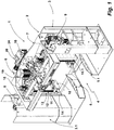
- a mixing machine 1 is used for industrial mixing of mixing material contained in a mixing container, for example plastic granules.
- the mixing machine 1 has a frame 2, which is provided in the illustrated embodiment by two stands 3, 3.1. Between the uprights 3, 3.1 is located in the area of the bottom of a container entrance 4.
- the container entrance 4 is laterally in the direction of the uprights 3, 3.1 limited by a respective side wall 5, 5.1.
- the two stands 3, 3.1 are connected to each other via a pivotable assembly 6.
- the pivotable assembly 6 comprises a frame member 7, on whose two narrow sides in each case a pivot shaft 8 is fixed.
- the pivot shaft 8 is mounted in the uprights 3, 3.1.
- In the stator 3 is an electric motor drive 9, with which the pivotable assembly 6 can be pivoted about the axis of its pivot shaft 8.
- the lifting devices 10, 10.1 have the same structure.
- the lifting device 10 is described by its basic structure. These statements apply equally to the lifting device 10.1.
- the lifting device 10 has a lifting plate 11 as part of a movable by a spindle 12 in the vertical direction Hubplattentician. On the lifting plate there is another plate which has a chamfer towards the container flange. This will center the container when lifted.
- the lifting plate unit is guided on a guide 13.
- the spindle 12 is driven by an electric motor. By means of the spindle 12, the Hubplattentician can be adjusted in the vertical direction. In FIG. 1 this is shown in its lowest position.
- Part of the Hubplatteniser is further a locking lever 14, which is about a vertical pivot axis from his in FIG. 1 shown basic position can be pivoted in the direction of mixing container recording.
- the pivoting of the locking lever 14 serves to lock a retracted into the container entrance 4 mixing container.
- the locking lever 4 acts against the outer wall of such a mixing container.
- the lifting device 10th is by means of an electric motor 15 as part of the pivotable assembly 6 in the direction of the longitudinal extent of the pivot axis of the pivotable assembly 6 movable.
- the electric motor 15 drives for this purpose in each case a spindle drive.
- the pivotable assembly further comprises a mixing head, of which in FIG. 1 its top (outside) is recognizable.
- the design of the mixing head 16 is in the front view of the mixing machine 1 of FIG. 2 recognizable.
- the mixing head 16 of the mixing machine 1 is designed as a lid for closing a mixing container open on the top side.
- the mixing head 16 includes a top plate 17. This will be described in more detail below with reference to FIGS FIGS. 3 to 5 described.
- Part of the mixing head 16 is one of the in FIG. 2 recognizable bottom of the top plate 17 spaced mixing tool 18, which is driven by an electric motor 19.
- the drive shaft of the electric motor 18 passes through the top plate 17th
- the arrangement of the mixing head 16 with respect to this supporting frame member 7 and the two lifting devices 10, 10.1 is from the bottom view of the pivotable assembly 6 of FIG. 3 recognizable.
- the mixing head 16 with the two lifting devices 10, 10.1 is gimballed within the frame member 7.
- the mixing head 16 can be pivoted with its two lifting devices 10, 10.1 about a transverse to the pivot axis of the frame member 7 axis of rotation.
- the mixing head 16 can be pivoted about two mutually perpendicular axes during operation of the mixing machine 1. This allows the implementation of a mixing process in which a mixing container connected to the mixing head 16 performs a multi-dimensional pendulum movement.
- the pivotable assembly relative to the frame is pivotable only on the previously described pivot shafts.
- the pivotable assembly is then not gimbaled, which is why in this embodiment, the present in the embodiment shown in the figures frame member is not present.
- the head plate 17 of the mixing machine 1 is a rotationally symmetric write (see FIG. 4 ), which is part of a head plate assembly 21.
- a cylindrical piece 22 is fixed, through which the drive shaft for driving the mixing tool 18 is guided.
- the drive shaft passes through the head plate 17 in its center, in which a drive shaft opening 23 is introduced for this purpose.
- opposing adapter shafts 24 attached on the lateral surface of the cylinder piece 22 . These serve to accommodate the mixing head 16 in the existing geometry.
- an opening 25 is also provided for a suction.
- the top plate 17 further carries a temperature sensor 26.
- the top plate 17 is, as shown in the sectional view of FIG. 5 recognizable as a flat plate performs.
- the outer edge region represents a connecting flange formed as an annular disc FIG. 5 the connection flange is designated by the reference numeral 27.
- the pointing away from the cylinder piece 22 top of the connecting flange 27 provides a contact surface for be connected to the mixing head 16 and its top plate 17 mixing container.
- three ring seals are integrated, as in the detailed view of FIG. 5 recognizable.
- Two seals are activatable ring seals 28, 28.1. These are arranged concentrically and at a distance from each other and surround the drive shaft opening 23 and thus the center axis of the top plate 17 concentrically.
- the activatable ring seals 28, 28.1 each have a circumferential hollow chamber 30 and a fluid port 31, with which they are connected to a compressed air source (not shown).
- the ring seals 28, 28.1 are inflatable and seated in a direction of the contact surface of the connecting flange 27 undercut groove 32. The protruding into the groove opening portion 33 of the ring seals 28 closes with its outer side 34 flush with the contact surface 35 of the Connection flange 27 from when the ring seal 28 is not activated.
- the lifting devices 10, 10.1 are adjustable in the radial direction to the top plate 17 by the above-described spindle drive.
- FIG. 6 shows in a perspective view, the lifting device 10.1.
- FIG. 1 described parts are identified therein by their reference numerals.
- Part of the pivotable assembly 6 is further a Einfahrbegrenzung, which is provided in the mixing machine 1 by a Einfahrbegrenzungsbauteil 36.
- the Einfahrbegrenzungsbauteil 36 is in a perspective view in FIG. 7 shown.
- FIG. 3 shows the arrangement of this component 36 with respect to the mixing head 16 and the two lifting devices 10, 10.1.
- the Einfahrbegrenzungsbauteil 36 has an adjustable in the radial direction to the center axis of the top plate 17 container stop 37, which is provided in the illustrated embodiment by three plate-like components with a vertical extension, which each have a narrow side in the direction of the container entrance 4.
- the retraction limit provided by the retraction limiting member 36 serves to adapt it to mixing containers different in diameter, which are to be connected to the mixing head 16 of the mixing machine 1 for the purpose of mixing a mixed material therein.
- FIG. 9 shown side view with removed side wall the structure of the Einfahrbegrenzungsbauteils 36 can be seen.
- the container stop 37 is adjustable by means of a pneumatic cylinder 38 in the radial direction.
- FIG. 8 shows the Einfahrbegrenzungsbauteil 36 with its container stopper 37 in that position in which this component is 36, when the largest possible diameter mixing container is to be connected to the mixing head 16 of the mixing machine 1 and for this purpose with its connection flange for sealing against the ring seal 28.1 acts.
- the container stopper 37 is connected by a piston rod 39 to the pneumatic cylinder 38.
- a piston rod 39 to the pneumatic cylinder 38.
- the locking pin 41 is in the transverse direction to the adjustment of the container stop 37, in FIG. 8 indicated by a block arrow, adjustable and protects the piston-cylinder unit for adjusting the container stop 37 before mixing container stops.
- FIG. 9 shows the Einfahrbegrenzungsbauteil 36 in an extended position in which its container stopper 37 is then when a mixing container is to be connected to the mixing head 16 of the mixing machine 1, the connecting flange acts against the inner ring seal 28, thus the diameter of this mixing container is smaller than the one whose connection flange acts to seal against the ring seal 28.1.
- the locking pin 41 is located to secure this position in a correspondingly different section of Arretierkulisse 40.
- the locking pin 41 is also controlled by a pneumatic cylinder so that it can be brought out of his engaging in a section of Arretierkulisse 41 position for adjustment of the container stop 37 ( not recognizable due to the perspective in the figures). In FIG. 8 this adjustment movement is indicated by an arrow arranged adjacent to the locking pin 41.
- FIG. 10 shows in its upper figure, the mixing machine M 1 when receiving a smaller diameter mixing container.
- the two lifting devices 10, 10.1 have in the in FIG. 10 Position shown above with their lifting plates 11 outwardly projecting annular flange 42 of the mixing container M 1 underrides.
- the mixing container M 1 has been retracted so far in the container entrance 4 for this purpose until a Wall outside 43 to the container stopper 37 in his in FIG. 9 position shown abuts.
- the locking lever 14 are in their locked position and also act against the wall outer side 43 of the mixing container M first By operating the lifting device 10, 10.1, the mixing container M 1 is lifted and moved with its connecting flange 42 against the top plate 17.
- connection flange 42 acts with its upper side against the annular seal 28, which is activated when the connection flange 42 of the mixing container M 1 is moved against the contact surface 35 of the connecting flange 27 of the top plate 17 of the mixing head 16.
- the pivotable assembly 6 is first pivoted in an overhead position.
- FIG. 11 Exemplary is in FIG. 11 the same sequence of figures shown as to FIG. 10 , However, the mixing container M 2 has a larger diameter than the mixing container M 1 . Accordingly, the Einfahrbegrenzungsbauteil 36 is in his in FIG. 8 shown position. Likewise, the lifting devices 10, 10. 1 are located in a position opposite to the position in FIG FIG. 10 radially further outward position.
- FIG. 12a shows a schematic representation of the connection of the connecting flange 42 of the mixing container M 1 to the connecting flange 27 of the top plate 17.
- the connecting flange 42 acts against the outside 34 of the ring seal 28, when activated.
- FIG. 12b shows the same section of the top plate 17 with the mixing container M 2 connected thereto, the connecting flange acts against the ring seal 28.1.
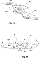
- a mixing tool 51 for an industrial mixing machine for mixing, for example, plastic granules in connection with the production of PCV is produced in the illustrated embodiment as a bent part made of stainless steel.
- the mixing tool 51 comprises a hub 52 with a shaft passage 53.
- the shaft passage 53 has two key spring receptacles 54, 54.1, which are at an angular distance of 90 degrees are arranged to each other.
- the tool shaft, on which the mixing tool 51 is to be mounted, has a feather key, so that the mixing tool 51 can be fixed in relation to the key of the tool shaft in two different positions on this.
- the hub 52 forms the central or central component of the mixing tool 51. Formed on the hub 52 are two mutually diametrically opposed to the axis of rotation mixing blades 55, 55.1.
- the mixing tool blades 55, 55.1 are constructed similarly, thus point-symmetrical to the axis of rotation D (s. FIG. 14 ).
- the mixing blade 55 is described in more detail below. The same statements apply equally to the mixing blade 55.1.
- the mixing blade 55 includes a connecting portion 56 and a mixing blade portion 57.
- the connecting portion 56 is formed at an angle to the hub 52.
- the angle that the connecting portion 56 occupies with the plane of the hub 52 is typically between 30 to 45 degrees. In the illustrated embodiment, this angle ⁇ is 42 degrees (see also FIG. 15b ).
- the mixing blade portion 57 is angled relative to the plane of the connecting portion 56, along a bending line 59 (s. FIG. 14 ).
- the bending line 59 does not run transversely to the longitudinal extension of the mixing tool blade 55, but with a certain inclination, which in the illustrated embodiment is made at about 33 degrees with respect to a transverse bending line. In FIG. 14 this angle is indicated by ⁇ . Due to this orientation of the bending line 59, with which the mixing blade portion 57 is angled relative to the connecting portion 56, the mixing blade portion 57 is made relative to the plane of the hub 52, seen in the direction of rotation and in the radial direction. This causes a left-handed drive of the mixing tool 51, as in FIG.
- the plan view of the development of the mixing tool 51 in the FIG. 14 makes it clear that the mixing vanes 55, 55.1 with respect to a central longitudinal plane, the track in FIG. 14 indicated by the reference M, are executed asymmetrically.
- the in a left-handed drive of the mixing tool 51 facing in the direction of rotation end face is designed sickle-shaped in the illustrated embodiment in the region of the mixing blade section 57. This supports the energy input into the mix to be mixed.
- the sickle-shaped design of pointing in a left-handed drive in the direction of rotation end face of the mixing blade section 57 supports a Mischgut lacking of the mixing tool 51 enclosing wall of a mixing container directed away.
- the crescent-shaped portion of this end face of the mixing blade section 57 is designed as a cutting edge. Due to the employment of the mixing blade section 57, the upper edge of this end face in the direction of rotation, so that a certain cutting or homogenization effect is achieved by this.
- the asymmetrical design of the mixing blade section 57 is due to the fact that both end faces of the mixing blade section 57 are brought together in a mixing blade tip 60.
- the mixing blade tip 60 is located in the extension of the left-hand drive in the direction of rotation facing, just running, integrally formed on the hub 52 end face portion. Starting from the mixing blade tip 60 is the other end face rounded, wherein in the illustrated embodiment, a constant radius of curvature has been selected before this end goes into its straight, integrally formed on the hub 52 end face portion.
- the mixing blade portion 57 is angled with respect to the connecting portion 56 along the bending line 59 in the illustrated embodiment with an angle of 110 degrees (s. FIG. 15c ).
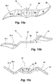
- FIGS. 15a-15c show different views of the mixing tool 51.
- FIG. 15a shows the mixing tool 51 in a plan view.
- FIG. 15b shows the mixing tool 51 in a side view of the hub 52.
- the employment of the mixing blade sections 57, 57.1 can be clearly seen. It can also be seen that the mixing blade sections 57, 57.1 are located in different planes with respect to the longitudinal extent of the axis of rotation D.
- FIG. 15c shows a side view of the end faces of the mixing blade sections 57, 57.1. Due to their employment, the hub 52 can be seen in a perspective view in this illustration of the mixing tool 51.
- the mixing machine 1 can be operated with a mixing tool 51, as described above, for mixing of mixed material.
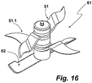
- the mixing time for a mixing process can be reduced if, instead of a single mixing tool 51, two mixing tools of this type are used, which then form a mixing tool set.
- a mixing tool set composed of two mixing tools 51, 51.1, is in FIG. 16 shown in a perspective view.
- both mixing tools 51, 51.1 are oriented in the same direction with respect to each other, but offset by 90 degrees on a tool shaft of a mixing machine not otherwise shown.
- Such an assembly is made possible by the two key spring receptacles 54, 54.1, which are introduced into the shaft passage 53 of the hub 52.
- the mixing tool set 61 of the embodiment of FIG. 15 is next to the two mixing tools 51, 51.1 still a soil clearing Tool 62 associated. This sits together with the two mixing tools 51, 51.1 on the same tool shaft.
- the soil clearing tool 62 is located in the immediate vicinity of the bottom of a mixing container, not shown in the figures.
- the soil-clearing tool 62 is inclined in the direction of rotation and serves the purpose of lifting in the region of the bottom of the mixing head 16 befindliches mix and feed the mixing tools 51, 51.1.
Landscapes
- Chemical & Material Sciences (AREA)
- Chemical Kinetics & Catalysis (AREA)
- Mixers Of The Rotary Stirring Type (AREA)
- Processing And Handling Of Plastics And Other Materials For Molding In General (AREA)
Applications Claiming Priority (2)
| Application Number | Priority Date | Filing Date | Title |
|---|---|---|---|
| DE202018100933.8U DE202018100933U1 (de) | 2018-02-20 | 2018-02-20 | Mischmaschine |
| DE202019100576.9U DE202019100576U1 (de) | 2019-01-31 | 2019-01-31 | Mischwerkzeug für eine industrielle Mischmaschine, Mischwerkzeugsatz mit derartigen Mischwerkzeugen sowie Mischvorrichtung mit einem solchen Mischwerkzeugsatz |
Publications (3)
| Publication Number | Publication Date |
|---|---|
| EP3530348A2 true EP3530348A2 (fr) | 2019-08-28 |
| EP3530348A3 EP3530348A3 (fr) | 2019-11-27 |
| EP3530348B1 EP3530348B1 (fr) | 2021-09-08 |
Family
ID=65440860
Family Applications (1)
| Application Number | Title | Priority Date | Filing Date |
|---|---|---|---|
| EP19157179.3A Active EP3530348B1 (fr) | 2018-02-20 | 2019-02-14 | Machine à mélanger |
Country Status (3)
| Country | Link |
|---|---|
| US (1) | US11059005B2 (fr) |
| EP (1) | EP3530348B1 (fr) |
| ES (1) | ES2899452T3 (fr) |
Families Citing this family (9)
| Publication number | Priority date | Publication date | Assignee | Title |
|---|---|---|---|---|
| US11224848B2 (en) | 2018-02-20 | 2022-01-18 | Dr. Herfeld Gmbh & Co. Kg | Mixing machine |
| ES2899452T3 (es) * | 2018-02-20 | 2022-03-11 | Dr Herfeld Gmbh & Co Kg | Máquina mezcladora |
| DE102018106189A1 (de) * | 2018-03-16 | 2019-09-19 | Maschinenfabrik Gustav Eirich Gmbh & Co. Kg | Hygienemischer |
| DE202019104870U1 (de) * | 2019-09-04 | 2019-09-18 | Dr. Herfeld Gmbh & Co. Kg | Mischmaschine |
| CN113680224A (zh) * | 2020-05-19 | 2021-11-23 | 彼特威有限责任公司 | 气体燃烧器的气体/空气混合装置 |
| DE102020129866A1 (de) * | 2020-11-12 | 2022-05-12 | Zeppelin Systems Gmbh | Dichtungsvorrichtung |
| ES2995973T3 (en) | 2021-11-30 | 2025-02-11 | Dr Herfeld Gmbh & Co Kg | Industrial mixer |
| JP7722954B2 (ja) * | 2022-03-22 | 2025-08-13 | 株式会社日清製粉グループ本社 | 容器回転式混合機及び混合方法 |
| DE202022106589U1 (de) | 2022-11-24 | 2024-02-27 | Zeppelin Systems Gmbh | Einzugsvorrichtung für einen Mischcontainer |
Citations (1)
| Publication number | Priority date | Publication date | Assignee | Title |
|---|---|---|---|---|
| EP0225495A2 (fr) | 1985-12-12 | 1987-06-16 | Dr. HERFELD GmbH & Co. KG | Mélangeur |
Family Cites Families (15)
| Publication number | Priority date | Publication date | Assignee | Title |
|---|---|---|---|---|
| US2149142A (en) * | 1938-05-24 | 1939-02-28 | Landon P Smith Inc | Holder |
| US3262680A (en) * | 1963-09-24 | 1966-07-26 | Baker Perkins Inc | Mixer for mixing potentially explosive materials |
| US3284057A (en) * | 1965-07-07 | 1966-11-08 | Robert J Duquette | Combination paint mixing and can closing devices |
| US4042221A (en) * | 1974-04-22 | 1977-08-16 | Myers Claude K | Tilt mixer |
| DE3433693A1 (de) * | 1984-09-13 | 1986-03-20 | Herfeld, Friedrich Walter, Dr., 5982 Neuenrade | Mischvorrichtung |
| DE19708075C1 (de) | 1997-02-28 | 1998-11-05 | Thyssen Industrie | Mischer für einen pulverförmigen, grießförmigen und/oder granulatförmigen Stoff |
| JP4796647B2 (ja) * | 2007-07-13 | 2011-10-19 | 株式会社仲田コーティング | 攪拌装置及び攪拌装置用治具 |
| DE202009001937U1 (de) * | 2009-03-04 | 2009-04-30 | Mixaco Dr. Herfeld Gmbh & Co. Kg | Mischmaschine |
| DE202009004866U1 (de) | 2009-05-26 | 2010-10-14 | Dr. Herfeld Gmbh & Co. Kg | Kühlmischer |
| CN202528756U (zh) * | 2012-04-30 | 2012-11-14 | 沈如华 | 适用于双旋转混匀机的色漆桶固定压紧装置 |
| DE202013103591U1 (de) | 2013-08-09 | 2013-08-27 | Dr. Herfeld Gmbh & Co Kg | Inliner zum Auskleiden eines Mischcontainers sowie Anordnung umfassend einen Mischcontainer sowie einen darin eingesetzten Inliner |
| DE202014101787U1 (de) | 2014-04-15 | 2014-04-30 | Dr. Herfeld Gmbh & Co. Kg | Mischmaschine |
| DE202015103285U1 (de) | 2015-06-23 | 2016-09-26 | Dr. Herfeld Gmbh & Co. Kg | Mischcontainer sowie Entleerstation für einen solchen Mischcontainer |
| DE202015103284U1 (de) | 2015-06-23 | 2016-09-26 | Dr. Herfeld Gmbh & Co Kg | Mischmaschine sowie Inliner dafür |
| ES2899452T3 (es) * | 2018-02-20 | 2022-03-11 | Dr Herfeld Gmbh & Co Kg | Máquina mezcladora |
-
2019
- 2019-02-14 ES ES19157179T patent/ES2899452T3/es active Active
- 2019-02-14 EP EP19157179.3A patent/EP3530348B1/fr active Active
- 2019-02-20 US US16/280,282 patent/US11059005B2/en active Active
Patent Citations (1)
| Publication number | Priority date | Publication date | Assignee | Title |
|---|---|---|---|---|
| EP0225495A2 (fr) | 1985-12-12 | 1987-06-16 | Dr. HERFELD GmbH & Co. KG | Mélangeur |
Also Published As
| Publication number | Publication date |
|---|---|
| EP3530348B1 (fr) | 2021-09-08 |
| US20190255493A1 (en) | 2019-08-22 |
| US11059005B2 (en) | 2021-07-13 |
| ES2899452T3 (es) | 2022-03-11 |
| EP3530348A3 (fr) | 2019-11-27 |
Similar Documents
| Publication | Publication Date | Title |
|---|---|---|
| EP3530348B1 (fr) | Machine à mélanger | |
| EP0439689B1 (fr) | Mélangeur granulateur | |
| EP0379834B1 (fr) | Dispositif d'accouplement, notamment pour disperseur | |
| DE202014101787U1 (de) | Mischmaschine | |
| EP3789108B1 (fr) | Machine à mélanger industrielle | |
| DE69700463T2 (de) | Rührdeckel für Farbbehälter, befestigt auf Farbrührmaschinen | |
| EP0286837B1 (fr) | Unité de coupe | |
| EP2158961B1 (fr) | Dispositif de mélange et agencement de dispositif de mélange | |
| DE102014101245B3 (de) | Mit mehrfach freigängiger Verriegelung versehener Tragarm | |
| DE202019105119U1 (de) | Mischmaschine | |
| EP2158960A1 (fr) | Procédé de mélange d'un produit à mélanger se trouvant dans un récipient de mélange et dispositif de mélange | |
| DE202018100933U1 (de) | Mischmaschine | |
| DE1427551C3 (de) | Spiralbohrerschleifmaschine | |
| DE2230357A1 (de) | Vorrichtung zum fuehren eines werkzeuges zum klarschleifen und polieren von torischen linsen | |
| DE202019104874U1 (de) | Mischmaschine | |
| EP3883678A1 (fr) | Outil de mélange pour machine de mélange industrielle, ensemble d'outils de mélange comportant de tels outils de mélange et machine de mélange comportant un tel ensemble d'outils de mélange | |
| DE102004015823B4 (de) | Anschlagmodul für eine Schwenkeinheit zum Begrenzen einer Schwenkbewegung und Schwenkeinheit | |
| DE102019123666B3 (de) | Mischmaschine | |
| DE10311298B4 (de) | Kupplungssystem zum fernbetätigbaren Kuppeln und Entkuppeln eines Roboters mit einer Dichtung | |
| DE1627262C3 (de) | Antriebsvorrichtung für linear bewegte Werkzeuge, wie Feilen, Schaber oddgl | |
| DE19749531C1 (de) | Vorrichtung zum Überführen von Fluiden von einem stehenden in ein drehendes Maschinenteil | |
| DE69716627T2 (de) | Vorrichtung zur Granulierung und/oder Beschichtung von Feststoffen | |
| DE3618620A1 (de) | Vorrichtung zum automatischen zufuehren und eindrehen von schrauben | |
| EP4656333A1 (fr) | Ensemble articulation rotative pour robot | |
| DE2929524A1 (de) | Mahlmaschine |
Legal Events
| Date | Code | Title | Description |
|---|---|---|---|
| PUAI | Public reference made under article 153(3) epc to a published international application that has entered the european phase |
Free format text: ORIGINAL CODE: 0009012 |
|
| STAA | Information on the status of an ep patent application or granted ep patent |
Free format text: STATUS: THE APPLICATION HAS BEEN PUBLISHED |
|
| AK | Designated contracting states |
Kind code of ref document: A2 Designated state(s): AL AT BE BG CH CY CZ DE DK EE ES FI FR GB GR HR HU IE IS IT LI LT LU LV MC MK MT NL NO PL PT RO RS SE SI SK SM TR |
|
| AX | Request for extension of the european patent |
Extension state: BA ME |
|
| STAA | Information on the status of an ep patent application or granted ep patent |
Free format text: STATUS: REQUEST FOR EXAMINATION WAS MADE |
|
| PUAL | Search report despatched |
Free format text: ORIGINAL CODE: 0009013 |
|
| 17P | Request for examination filed |
Effective date: 20190919 |
|
| RBV | Designated contracting states (corrected) |
Designated state(s): AL AT BE BG CH CY CZ DE DK EE ES FI FR GB GR HR HU IE IS IT LI LT LU LV MC MK MT NL NO PL PT RO RS SE SI SK SM TR |
|
| AK | Designated contracting states |
Kind code of ref document: A3 Designated state(s): AL AT BE BG CH CY CZ DE DK EE ES FI FR GB GR HR HU IE IS IT LI LT LU LV MC MK MT NL NO PL PT RO RS SE SI SK SM TR |
|
| AX | Request for extension of the european patent |
Extension state: BA ME |
|
| RIC1 | Information provided on ipc code assigned before grant |
Ipc: B01F 13/00 20060101AFI20191022BHEP Ipc: B01F 11/00 20060101ALI20191022BHEP Ipc: B01F 7/00 20060101ALI20191022BHEP Ipc: B01F 7/16 20060101ALI20191022BHEP Ipc: B01F 15/00 20060101ALI20191022BHEP |
|
| GRAP | Despatch of communication of intention to grant a patent |
Free format text: ORIGINAL CODE: EPIDOSNIGR1 |
|
| STAA | Information on the status of an ep patent application or granted ep patent |
Free format text: STATUS: GRANT OF PATENT IS INTENDED |
|
| INTG | Intention to grant announced |
Effective date: 20210511 |
|
| RIN1 | Information on inventor provided before grant (corrected) |
Inventor name: KIND, MARVIN Inventor name: TOELLE, MATTHIAS Inventor name: SCHWEINSBERG, NADINE Inventor name: RUEBERG, WOLFGANG |
|
| GRAS | Grant fee paid |
Free format text: ORIGINAL CODE: EPIDOSNIGR3 |
|
| GRAA | (expected) grant |
Free format text: ORIGINAL CODE: 0009210 |
|
| STAA | Information on the status of an ep patent application or granted ep patent |
Free format text: STATUS: THE PATENT HAS BEEN GRANTED |
|
| AK | Designated contracting states |
Kind code of ref document: B1 Designated state(s): AL AT BE BG CH CY CZ DE DK EE ES FI FR GB GR HR HU IE IS IT LI LT LU LV MC MK MT NL NO PL PT RO RS SE SI SK SM TR |
|
| REG | Reference to a national code |
Ref country code: GB Ref legal event code: FG4D Free format text: NOT ENGLISH |
|
| REG | Reference to a national code |
Ref country code: CH Ref legal event code: EP Ref country code: AT Ref legal event code: REF Ref document number: 1428064 Country of ref document: AT Kind code of ref document: T Effective date: 20210915 |
|
| REG | Reference to a national code |
Ref country code: IE Ref legal event code: FG4D Free format text: LANGUAGE OF EP DOCUMENT: GERMAN |
|
| REG | Reference to a national code |
Ref country code: DE Ref legal event code: R096 Ref document number: 502019002217 Country of ref document: DE |
|
| REG | Reference to a national code |
Ref country code: DE Ref legal event code: R079 Ref document number: 502019002217 Country of ref document: DE Free format text: PREVIOUS MAIN CLASS: B01F0013000000 Ipc: B01F0033000000 |
|
| REG | Reference to a national code |
Ref country code: NL Ref legal event code: FP |
|
| REG | Reference to a national code |
Ref country code: LT Ref legal event code: MG9D |
|
| REG | Reference to a national code |
Ref country code: DE Ref legal event code: R082 Ref document number: 502019002217 Country of ref document: DE Representative=s name: HAVERKAMP PATENTANWAELTE PARTG MBB, DE |
|
| PG25 | Lapsed in a contracting state [announced via postgrant information from national office to epo] |
Ref country code: FI Free format text: LAPSE BECAUSE OF FAILURE TO SUBMIT A TRANSLATION OF THE DESCRIPTION OR TO PAY THE FEE WITHIN THE PRESCRIBED TIME-LIMIT Effective date: 20210908 Ref country code: RS Free format text: LAPSE BECAUSE OF FAILURE TO SUBMIT A TRANSLATION OF THE DESCRIPTION OR TO PAY THE FEE WITHIN THE PRESCRIBED TIME-LIMIT Effective date: 20210908 Ref country code: SE Free format text: LAPSE BECAUSE OF FAILURE TO SUBMIT A TRANSLATION OF THE DESCRIPTION OR TO PAY THE FEE WITHIN THE PRESCRIBED TIME-LIMIT Effective date: 20210908 Ref country code: LT Free format text: LAPSE BECAUSE OF FAILURE TO SUBMIT A TRANSLATION OF THE DESCRIPTION OR TO PAY THE FEE WITHIN THE PRESCRIBED TIME-LIMIT Effective date: 20210908 Ref country code: BG Free format text: LAPSE BECAUSE OF FAILURE TO SUBMIT A TRANSLATION OF THE DESCRIPTION OR TO PAY THE FEE WITHIN THE PRESCRIBED TIME-LIMIT Effective date: 20211208 Ref country code: HR Free format text: LAPSE BECAUSE OF FAILURE TO SUBMIT A TRANSLATION OF THE DESCRIPTION OR TO PAY THE FEE WITHIN THE PRESCRIBED TIME-LIMIT Effective date: 20210908 Ref country code: NO Free format text: LAPSE BECAUSE OF FAILURE TO SUBMIT A TRANSLATION OF THE DESCRIPTION OR TO PAY THE FEE WITHIN THE PRESCRIBED TIME-LIMIT Effective date: 20211208 |
|
| PG25 | Lapsed in a contracting state [announced via postgrant information from national office to epo] |
Ref country code: LV Free format text: LAPSE BECAUSE OF FAILURE TO SUBMIT A TRANSLATION OF THE DESCRIPTION OR TO PAY THE FEE WITHIN THE PRESCRIBED TIME-LIMIT Effective date: 20210908 Ref country code: GR Free format text: LAPSE BECAUSE OF FAILURE TO SUBMIT A TRANSLATION OF THE DESCRIPTION OR TO PAY THE FEE WITHIN THE PRESCRIBED TIME-LIMIT Effective date: 20211209 |
|
| REG | Reference to a national code |
Ref country code: ES Ref legal event code: FG2A Ref document number: 2899452 Country of ref document: ES Kind code of ref document: T3 Effective date: 20220311 |
|
| PG25 | Lapsed in a contracting state [announced via postgrant information from national office to epo] |
Ref country code: IS Free format text: LAPSE BECAUSE OF FAILURE TO SUBMIT A TRANSLATION OF THE DESCRIPTION OR TO PAY THE FEE WITHIN THE PRESCRIBED TIME-LIMIT Effective date: 20220108 Ref country code: SM Free format text: LAPSE BECAUSE OF FAILURE TO SUBMIT A TRANSLATION OF THE DESCRIPTION OR TO PAY THE FEE WITHIN THE PRESCRIBED TIME-LIMIT Effective date: 20210908 Ref country code: SK Free format text: LAPSE BECAUSE OF FAILURE TO SUBMIT A TRANSLATION OF THE DESCRIPTION OR TO PAY THE FEE WITHIN THE PRESCRIBED TIME-LIMIT Effective date: 20210908 Ref country code: RO Free format text: LAPSE BECAUSE OF FAILURE TO SUBMIT A TRANSLATION OF THE DESCRIPTION OR TO PAY THE FEE WITHIN THE PRESCRIBED TIME-LIMIT Effective date: 20210908 Ref country code: PT Free format text: LAPSE BECAUSE OF FAILURE TO SUBMIT A TRANSLATION OF THE DESCRIPTION OR TO PAY THE FEE WITHIN THE PRESCRIBED TIME-LIMIT Effective date: 20220110 Ref country code: PL Free format text: LAPSE BECAUSE OF FAILURE TO SUBMIT A TRANSLATION OF THE DESCRIPTION OR TO PAY THE FEE WITHIN THE PRESCRIBED TIME-LIMIT Effective date: 20210908 Ref country code: EE Free format text: LAPSE BECAUSE OF FAILURE TO SUBMIT A TRANSLATION OF THE DESCRIPTION OR TO PAY THE FEE WITHIN THE PRESCRIBED TIME-LIMIT Effective date: 20210908 Ref country code: CZ Free format text: LAPSE BECAUSE OF FAILURE TO SUBMIT A TRANSLATION OF THE DESCRIPTION OR TO PAY THE FEE WITHIN THE PRESCRIBED TIME-LIMIT Effective date: 20210908 Ref country code: AL Free format text: LAPSE BECAUSE OF FAILURE TO SUBMIT A TRANSLATION OF THE DESCRIPTION OR TO PAY THE FEE WITHIN THE PRESCRIBED TIME-LIMIT Effective date: 20210908 |
|
| REG | Reference to a national code |
Ref country code: DE Ref legal event code: R097 Ref document number: 502019002217 Country of ref document: DE |
|
| PLBE | No opposition filed within time limit |
Free format text: ORIGINAL CODE: 0009261 |
|
| STAA | Information on the status of an ep patent application or granted ep patent |
Free format text: STATUS: NO OPPOSITION FILED WITHIN TIME LIMIT |
|
| PG25 | Lapsed in a contracting state [announced via postgrant information from national office to epo] |
Ref country code: DK Free format text: LAPSE BECAUSE OF FAILURE TO SUBMIT A TRANSLATION OF THE DESCRIPTION OR TO PAY THE FEE WITHIN THE PRESCRIBED TIME-LIMIT Effective date: 20210908 |
|
| 26N | No opposition filed |
Effective date: 20220609 |
|
| PG25 | Lapsed in a contracting state [announced via postgrant information from national office to epo] |
Ref country code: SI Free format text: LAPSE BECAUSE OF FAILURE TO SUBMIT A TRANSLATION OF THE DESCRIPTION OR TO PAY THE FEE WITHIN THE PRESCRIBED TIME-LIMIT Effective date: 20210908 |
|
| PG25 | Lapsed in a contracting state [announced via postgrant information from national office to epo] |
Ref country code: MC Free format text: LAPSE BECAUSE OF FAILURE TO SUBMIT A TRANSLATION OF THE DESCRIPTION OR TO PAY THE FEE WITHIN THE PRESCRIBED TIME-LIMIT Effective date: 20210908 |
|
| REG | Reference to a national code |
Ref country code: CH Ref legal event code: PL |
|
| PG25 | Lapsed in a contracting state [announced via postgrant information from national office to epo] |
Ref country code: LU Free format text: LAPSE BECAUSE OF NON-PAYMENT OF DUE FEES Effective date: 20220214 |
|
| PG25 | Lapsed in a contracting state [announced via postgrant information from national office to epo] |
Ref country code: FR Free format text: LAPSE BECAUSE OF NON-PAYMENT OF DUE FEES Effective date: 20220228 |
|
| PG25 | Lapsed in a contracting state [announced via postgrant information from national office to epo] |
Ref country code: LI Free format text: LAPSE BECAUSE OF NON-PAYMENT OF DUE FEES Effective date: 20220228 Ref country code: IE Free format text: LAPSE BECAUSE OF NON-PAYMENT OF DUE FEES Effective date: 20220214 Ref country code: CH Free format text: LAPSE BECAUSE OF NON-PAYMENT OF DUE FEES Effective date: 20220228 |
|
| P01 | Opt-out of the competence of the unified patent court (upc) registered |
Effective date: 20230529 |
|
| GBPC | Gb: european patent ceased through non-payment of renewal fee |
Effective date: 20230214 |
|
| PG25 | Lapsed in a contracting state [announced via postgrant information from national office to epo] |
Ref country code: GB Free format text: LAPSE BECAUSE OF NON-PAYMENT OF DUE FEES Effective date: 20230214 |
|
| PG25 | Lapsed in a contracting state [announced via postgrant information from national office to epo] |
Ref country code: GB Free format text: LAPSE BECAUSE OF NON-PAYMENT OF DUE FEES Effective date: 20230214 |
|
| PG25 | Lapsed in a contracting state [announced via postgrant information from national office to epo] |
Ref country code: MK Free format text: LAPSE BECAUSE OF FAILURE TO SUBMIT A TRANSLATION OF THE DESCRIPTION OR TO PAY THE FEE WITHIN THE PRESCRIBED TIME-LIMIT Effective date: 20210908 Ref country code: CY Free format text: LAPSE BECAUSE OF FAILURE TO SUBMIT A TRANSLATION OF THE DESCRIPTION OR TO PAY THE FEE WITHIN THE PRESCRIBED TIME-LIMIT Effective date: 20210908 |
|
| PG25 | Lapsed in a contracting state [announced via postgrant information from national office to epo] |
Ref country code: HU Free format text: LAPSE BECAUSE OF FAILURE TO SUBMIT A TRANSLATION OF THE DESCRIPTION OR TO PAY THE FEE WITHIN THE PRESCRIBED TIME-LIMIT; INVALID AB INITIO Effective date: 20190214 |
|
| PG25 | Lapsed in a contracting state [announced via postgrant information from national office to epo] |
Ref country code: TR Free format text: LAPSE BECAUSE OF FAILURE TO SUBMIT A TRANSLATION OF THE DESCRIPTION OR TO PAY THE FEE WITHIN THE PRESCRIBED TIME-LIMIT Effective date: 20210908 |
|
| PG25 | Lapsed in a contracting state [announced via postgrant information from national office to epo] |
Ref country code: MT Free format text: LAPSE BECAUSE OF FAILURE TO SUBMIT A TRANSLATION OF THE DESCRIPTION OR TO PAY THE FEE WITHIN THE PRESCRIBED TIME-LIMIT Effective date: 20210908 |
|
| PGFP | Annual fee paid to national office [announced via postgrant information from national office to epo] |
Ref country code: NL Payment date: 20260218 Year of fee payment: 8 |
|
| PGFP | Annual fee paid to national office [announced via postgrant information from national office to epo] |
Ref country code: ES Payment date: 20260319 Year of fee payment: 8 |
|
| PGFP | Annual fee paid to national office [announced via postgrant information from national office to epo] |
Ref country code: DE Payment date: 20260119 Year of fee payment: 8 |
|
| PGFP | Annual fee paid to national office [announced via postgrant information from national office to epo] |
Ref country code: AT Payment date: 20260119 Year of fee payment: 8 |
|
| PGFP | Annual fee paid to national office [announced via postgrant information from national office to epo] |
Ref country code: BE Payment date: 20260218 Year of fee payment: 8 Ref country code: IT Payment date: 20260227 Year of fee payment: 8 |