EP3530355A1 - Ausgabekopf mit einer abgestuften wirbelkammer für ein ausgabesystem - Google Patents
Ausgabekopf mit einer abgestuften wirbelkammer für ein ausgabesystem Download PDFInfo
- Publication number
- EP3530355A1 EP3530355A1 EP19157320.3A EP19157320A EP3530355A1 EP 3530355 A1 EP3530355 A1 EP 3530355A1 EP 19157320 A EP19157320 A EP 19157320A EP 3530355 A1 EP3530355 A1 EP 3530355A1
- Authority
- EP
- European Patent Office
- Prior art keywords
- wall
- dispensing
- axis
- core
- head
- Prior art date
- Legal status (The legal status is an assumption and is not a legal conclusion. Google has not performed a legal analysis and makes no representation as to the accuracy of the status listed.)
- Granted
Links
Images


Classifications
-
- B—PERFORMING OPERATIONS; TRANSPORTING
- B05—SPRAYING OR ATOMISING IN GENERAL; APPLYING FLUENT MATERIALS TO SURFACES, IN GENERAL
- B05B—SPRAYING APPARATUS; ATOMISING APPARATUS; NOZZLES
- B05B1/00—Nozzles, spray heads or other outlets, with or without auxiliary devices such as valves, heating means
- B05B1/34—Nozzles, spray heads or other outlets, with or without auxiliary devices such as valves, heating means designed to influence the nature of flow of the liquid or other fluent material, e.g. to produce swirl
- B05B1/3405—Nozzles, spray heads or other outlets, with or without auxiliary devices such as valves, heating means designed to influence the nature of flow of the liquid or other fluent material, e.g. to produce swirl to produce swirl
- B05B1/341—Nozzles, spray heads or other outlets, with or without auxiliary devices such as valves, heating means designed to influence the nature of flow of the liquid or other fluent material, e.g. to produce swirl to produce swirl before discharging the liquid or other fluent material, e.g. in a swirl chamber upstream the spray outlet
- B05B1/3421—Nozzles, spray heads or other outlets, with or without auxiliary devices such as valves, heating means designed to influence the nature of flow of the liquid or other fluent material, e.g. to produce swirl to produce swirl before discharging the liquid or other fluent material, e.g. in a swirl chamber upstream the spray outlet with channels emerging substantially tangentially in the swirl chamber
- B05B1/3431—Nozzles, spray heads or other outlets, with or without auxiliary devices such as valves, heating means designed to influence the nature of flow of the liquid or other fluent material, e.g. to produce swirl to produce swirl before discharging the liquid or other fluent material, e.g. in a swirl chamber upstream the spray outlet with channels emerging substantially tangentially in the swirl chamber the channels being formed at the interface of cooperating elements, e.g. by means of grooves
- B05B1/3442—Nozzles, spray heads or other outlets, with or without auxiliary devices such as valves, heating means designed to influence the nature of flow of the liquid or other fluent material, e.g. to produce swirl to produce swirl before discharging the liquid or other fluent material, e.g. in a swirl chamber upstream the spray outlet with channels emerging substantially tangentially in the swirl chamber the channels being formed at the interface of cooperating elements, e.g. by means of grooves the interface being a cone having the same axis as the outlet
-
- B—PERFORMING OPERATIONS; TRANSPORTING
- B05—SPRAYING OR ATOMISING IN GENERAL; APPLYING FLUENT MATERIALS TO SURFACES, IN GENERAL
- B05B—SPRAYING APPARATUS; ATOMISING APPARATUS; NOZZLES
- B05B1/00—Nozzles, spray heads or other outlets, with or without auxiliary devices such as valves, heating means
- B05B1/34—Nozzles, spray heads or other outlets, with or without auxiliary devices such as valves, heating means designed to influence the nature of flow of the liquid or other fluent material, e.g. to produce swirl
- B05B1/3405—Nozzles, spray heads or other outlets, with or without auxiliary devices such as valves, heating means designed to influence the nature of flow of the liquid or other fluent material, e.g. to produce swirl to produce swirl
- B05B1/341—Nozzles, spray heads or other outlets, with or without auxiliary devices such as valves, heating means designed to influence the nature of flow of the liquid or other fluent material, e.g. to produce swirl to produce swirl before discharging the liquid or other fluent material, e.g. in a swirl chamber upstream the spray outlet
- B05B1/3421—Nozzles, spray heads or other outlets, with or without auxiliary devices such as valves, heating means designed to influence the nature of flow of the liquid or other fluent material, e.g. to produce swirl to produce swirl before discharging the liquid or other fluent material, e.g. in a swirl chamber upstream the spray outlet with channels emerging substantially tangentially in the swirl chamber
- B05B1/3426—Nozzles, spray heads or other outlets, with or without auxiliary devices such as valves, heating means designed to influence the nature of flow of the liquid or other fluent material, e.g. to produce swirl to produce swirl before discharging the liquid or other fluent material, e.g. in a swirl chamber upstream the spray outlet with channels emerging substantially tangentially in the swirl chamber the channels emerging in the swirl chamber perpendicularly to the outlet axis
-
- B—PERFORMING OPERATIONS; TRANSPORTING
- B05—SPRAYING OR ATOMISING IN GENERAL; APPLYING FLUENT MATERIALS TO SURFACES, IN GENERAL
- B05B—SPRAYING APPARATUS; ATOMISING APPARATUS; NOZZLES
- B05B1/00—Nozzles, spray heads or other outlets, with or without auxiliary devices such as valves, heating means
- B05B1/34—Nozzles, spray heads or other outlets, with or without auxiliary devices such as valves, heating means designed to influence the nature of flow of the liquid or other fluent material, e.g. to produce swirl
- B05B1/3405—Nozzles, spray heads or other outlets, with or without auxiliary devices such as valves, heating means designed to influence the nature of flow of the liquid or other fluent material, e.g. to produce swirl to produce swirl
- B05B1/341—Nozzles, spray heads or other outlets, with or without auxiliary devices such as valves, heating means designed to influence the nature of flow of the liquid or other fluent material, e.g. to produce swirl to produce swirl before discharging the liquid or other fluent material, e.g. in a swirl chamber upstream the spray outlet
- B05B1/3421—Nozzles, spray heads or other outlets, with or without auxiliary devices such as valves, heating means designed to influence the nature of flow of the liquid or other fluent material, e.g. to produce swirl to produce swirl before discharging the liquid or other fluent material, e.g. in a swirl chamber upstream the spray outlet with channels emerging substantially tangentially in the swirl chamber
- B05B1/3463—Nozzles, spray heads or other outlets, with or without auxiliary devices such as valves, heating means designed to influence the nature of flow of the liquid or other fluent material, e.g. to produce swirl to produce swirl before discharging the liquid or other fluent material, e.g. in a swirl chamber upstream the spray outlet with channels emerging substantially tangentially in the swirl chamber the channels extending outwardly, e.g. radially from the inside to the outside
-
- B—PERFORMING OPERATIONS; TRANSPORTING
- B05—SPRAYING OR ATOMISING IN GENERAL; APPLYING FLUENT MATERIALS TO SURFACES, IN GENERAL
- B05B—SPRAYING APPARATUS; ATOMISING APPARATUS; NOZZLES
- B05B1/00—Nozzles, spray heads or other outlets, with or without auxiliary devices such as valves, heating means
- B05B1/34—Nozzles, spray heads or other outlets, with or without auxiliary devices such as valves, heating means designed to influence the nature of flow of the liquid or other fluent material, e.g. to produce swirl
- B05B1/3405—Nozzles, spray heads or other outlets, with or without auxiliary devices such as valves, heating means designed to influence the nature of flow of the liquid or other fluent material, e.g. to produce swirl to produce swirl
- B05B1/341—Nozzles, spray heads or other outlets, with or without auxiliary devices such as valves, heating means designed to influence the nature of flow of the liquid or other fluent material, e.g. to produce swirl to produce swirl before discharging the liquid or other fluent material, e.g. in a swirl chamber upstream the spray outlet
- B05B1/3489—Nozzles having concentric outlets
-
- B—PERFORMING OPERATIONS; TRANSPORTING
- B05—SPRAYING OR ATOMISING IN GENERAL; APPLYING FLUENT MATERIALS TO SURFACES, IN GENERAL
- B05B—SPRAYING APPARATUS; ATOMISING APPARATUS; NOZZLES
- B05B11/00—Single-unit hand-held apparatus in which flow of contents is produced by the muscular force of the operator at the moment of use
- B05B11/01—Single-unit hand-held apparatus in which flow of contents is produced by the muscular force of the operator at the moment of use characterised by the means producing the flow
- B05B11/10—Pump arrangements for transferring the contents from the container to a pump chamber by a sucking effect and forcing the contents out through the dispensing nozzle
- B05B11/1042—Components or details
- B05B11/1052—Actuation means
Definitions
- the invention relates to a spraying device, especially for a dispensing system of a product with a push button.
- the dispensing system is intended to equip bottles used in perfumery, in cosmetics or for pharmaceutical treatments.
- this type of bottle contains a product which is returned by the dispensing system comprising a device for sampling said product, said system being actuated for example by a push button to allow the product to be sprayed.
- the sampling device comprises a pump or a manually operated valve, for example by means of the push button.
- Such push buttons are conventionally made of at least two parts, including an actuating body and a spray nozzle which are assembled to one another.
- the nozzle generally comprises a swirl chamber provided with a dispensing orifice, as well as at least one supply channel of said chamber.
- the sampling device takes the product from the bottle by a dip tube, and pushes it inside the duct arranged in the pusher, which is the actuating element of the sampling device.
- This conduit opens into a so-called vortex chamber for rotating the liquid very quickly and thus to give it speed and the effects of centrifugal force.
- This vortex chamber is extended in its center by an outlet port through which the product escapes to the outside with a high speed. Moved by this speed, and subjected to centrifugal forces, the liquid splits into droplets and forms an aerosol.
- the size of the droplets from the vortex chamber depends in part on the force and speed with which the user actuates the pump by pressing the push button with his finger, as the induced pressure depends on it.
- one technology consists in using a vortex chamber of revolution.
- the stream rotates in the chamber in the form of a sheet which impinges on itself after its exit through the dispensing orifice.
- This technology is used for non-viscous products.
- the impaction of the layers does not occur correctly, for example when the viscosity is greater than 150 mPa.s. This results in too large droplet size and the cone of sprayed product is of poor quality.
- the steps make it possible to improve the impaction of the product plies and to obtain droplets of small dimensions, and this with a viscous product.
- the dimensions of the droplets are suitable in most of the spray cone which allows to obtain a cone of fine droplets of product.
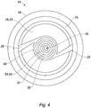
- a central zone of the cone does not have the required requirements. This central zone is located immediately downstream of the dispensing orifice in the direction of movement of the product, and extends substantially rectilinearly. In this central zone, the droplets have much larger dimensions than in the rest of the cone. It is common for a continuous stream in a central area to coexist with the peripheral droplets. In other words, the dimensions of the droplets are not uniform in the cone.
- a user then receives on his hands or another part of his body, the product in the form of a continuous stream in the central zone, and this in a cone of fine droplets.
- the experience of the product is therefore impaired. This is especially true for a clientele whose expectations are often high. In addition to the unpleasant sensation of continuous jet, this returns a deplorable image of the product and its manufacturer despite the cosmetic qualities it contains.
- the invention aims to solve this drawback.
- the convergent portion comprising an inner wall of the nozzle, said inner wall and / or the peripheral wall of the core is provided with a plurality of steps, each step being defined by a transverse wall which extends in a plane intersecting with the axis and a longitudinal wall substantially parallel to the axis, the steps forming obstacles in the fluid path.
- This dispensing head has the advantage of eliminating the continuous jet that appears in the central zone. This is made possible by the combined action of the convergent portion provided with steps and a core forming at least one fluidic path in which the product encounters obstacles. This is also made possible by the combined action of the converging part and a walking core as well as a converging part and a core, both provided with steps.
- the dispensing head is particularly advantageous when the product has a non-Newtonian rheofluidifying rheological behavior. This type of fluid becomes fluid as the shear rate increases. This type of product is widely used in the cosmetics industry.
- the central zone then comprises droplets whose dimensions are substantially identical throughout the cone.
- the invention also relates to a system for dispensing a product comprising a dispensing head as previously described.
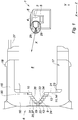
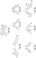
- a dispensing head 1 in particular for a distribution system (not shown) of a fluid product.
- the dispensing system comprises the dispensing head 1 and a sampling device (not shown) provided with a feed tube inserted into a well 2 located in the dispensing head 1.
- the dispensing head 1 comprises a body 3.
- the body 3 defines a bearing wall 4 situated on an upper part thereof.
- the support wall 4 allows the user to press the dispensing head 1 to spray product.
- the body 3 defines a housing 6.
- the housing 6 is in fluid communication with the well 2. This fluid communication is performed through an internal channel 27 made in the body 3.
- the body 3 comprises an anvil 8.
- the anvil 8 is manufactured in one piece with the dispensing head 1.
- the anvil 8 extends longitudinally along the axis X in the housing.
- the anvil 8 has a circular section in the plane ZY.
- the anvil 8 has a core 9 visible on the figures 1 and 3 .
- the core 9 is in the form of an X-axis protruding member of a distal surface of the anvil 8.
- the core 9 comprises a cylindrical portion 11.
- the cylindrical portion 11 is located at the base of the core and is adjacent to the distal surface of the turbulent anvil.
- the core 9 comprises a conical portion 12 of revolution about the axis X.
- the conical portion 12 extends from the cylindrical portion 11 and ends with a vertex 13.
- the vertex 13 is flat.
- the top 13 is in the form of a plane wall substantially perpendicular to the axis X.
- the cylindrical portion 11 and the conical portion 12 together form a peripheral wall 36 of the core 9.
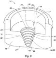
- the dispensing head 1 comprises a spray nozzle 14.
- the spray nozzle 14 is an element attached to the dispensing head 1.
- the spray nozzle 14 has an annular wall forming an open volume on one side and closed on the other by a distal wall.
- the spray nozzle 14 defines a central opening 17 laterally bordered along the Y and Z axes by the annular wall and longitudinally along the X axis by the distal wall 16.
- the annular wall comprises a locking tab 18.
- the locking lug 18 is in the form of a projecting annular rim extending along the perimeter of the annular wall.
- the distal wall 16 has a dispensing orifice 19 and a vortex chamber 20.
- the vortex chamber 20 opens into the dispensing orifice 19.
- the vortex chamber is rotated about the X axis.
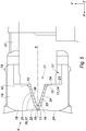
- the vortex chamber 20 comprises a convergent portion 37.
- Said Swirl chamber 20 includes an inner wall 35 and extends from an upstream end 21 coinciding with an inner surface 23 of the distal wall 16 to a downstream end 22.
- the downstream end 22 can be easily located by positioning in the dispensing orifice 19 and then moving along the X axis from an outer surface 24 of the distal wall 16.
- the dispensing orifice 19 is a cylinder of revolution, and the section thereof is substantially constant. Where the section begins to vary is the boundary between the dispensing orifice 19 and the vortex chamber 20 ie the downstream end.
- downstream end 22 of the vortex chamber 20 is the dispensing orifice 19.
- the dispensing orifice 19 coincides with the downstream end 22.
- the vortex chamber 20 further comprises a prechamber 50, located upstream of the convergent portion 37 of said vortex chamber.
- Said pre-chamber 50 is here annular. It is delimited by the cylindrical portion 11 of the core 9, the part facing the distal wall 16 of the nozzle, the distal surface 10 of the anvil and the convergent portion 37 of the vortex chamber.
- the upstream end of the chamber 20 corresponds to the upstream end of the prechamber 50.
- the dispensing nozzle 14 has at least one supply channel for the vortex chamber 20.
- the dispensing nozzle 14 comprises two feed channels.
- the supply channels are made in the distal wall.
- the supply channels open tangentially into the annular prechamber 50 belonging to the vortex chamber 20. They could lead in any other direction. In particular, the channels 25 could emerge in a direction tangential to the first step 30, immediately downstream of the prechamber 50.
- the prechamber 50 allows the rotation of the product around the cylindrical portion 11 of the core 9.
- the prechamber 50 annular has a length measured along the axis X equal to a depth of the supply channels measured along the axis X.
- the pre-chamber 50 annular is not a step in the sense given in the invention.
- the spray nozzle 14 is a separate element attached to the dispensing head 1. More specifically, the spraying nozzle 14 is inserted into the housing 6 and fixed to the body 3 by virtue of the locking tab 18 embedded in said body 3.
- the anvil 8 is arranged in part in the central opening 17 of the nozzle so that the distal surface abuts on the inner surface 23.
- the core 9 then lodges inside the vortex chamber 20.
- the peripheral wall 36 of the core 9 and the convergent portion 37 of the swirl chamber 20 form a fluid path in which the product from the supply channel flows.
- a step 30 is defined by a transverse wall 31 and a longitudinal wall 32.
- the transverse wall 31 extends in a plane intersecting with the axis X. Indeed by extending the transverse wall 31 in the direction of the axis X by means of an imaginary line on the figure 1 , the latter crosses the axis X.
- the longitudinal wall 32 is substantially parallel to the axis X. By extending the longitudinal wall 32 on either side at infinity with an imaginary line, it is substantially parallel to the X axis.
- the steps 30 form obstacles in the fluidic path. More specifically, the transverse walls 31 of the steps 30 form obstacles in the fluidic path.
- the combination of the steps 30 and a core 9 which extends into the vortex chamber 20 eliminates the continuous jet which appears in a central zone 28 of a cone 29 of sprayed droplets at the outlet of the orifice 19 of distribution.
- the combination of the core 9 and the steps 30 forming obstacles in the fluidic path advantageously makes it possible to obtain in the central zone 28 droplets of identical or similar size, to the droplets present in the rest of the cone. sprayed.
- the dimensions of the droplets in the cone 29 are substantially uniform.
- the transverse walls 31 are substantially orthogonal to the axis X. The impact with the product in the fluidic path is then abrupt in favor of a better impaction of the product on the steps 30.
- the transverse walls 31 are not orthogonal. In the latter case the impact energy between the product and the transverse walls is lower. The energy of the impact of the product against the steps 30 can be adjusted by changing the angle formed by the transverse walls with the X axis.
- Each transverse wall 31 crosses at each of its ends a longitudinal wall 32.
- these crossings are referred to as nosing 33 and walking recess 34 as a function of their distance in the plane ZY of the peripheral wall 36 of the core 9.
- the nosing 33 is located at a proximal distance between 70 and 250 micrometers of the peripheral wall of the core 9. figure 1 this proximal distance is measured along an imaginary straight line drawn from the walking nose 33 to the peripheral wall 36 along the shortest route. Preferably the proximal distance is about 160 micrometers.
- the proximal distance included in the range mentioned above and more particularly the specified value allow shear sufficient product in the vicinity of the nosing 33 against the peripheral wall wall of the core 9. This results in a localized increase in the rate shear induced by the wall 36 device in the vicinity of the noses 33 of walking to reduce the viscosity of the product. In other words, this makes it possible to thin the product.
- the convergent portion 37 of the vortex chamber 20 comprises between three and fifteen steps 30 and preferably four steps 30.
- the convergent portion 37 preferably comprises four transverse walls 31 and four walls 32 longitudinal. This makes it possible to obtain significant results with a total or almost total elimination of a continuous jet in the central zone.
- the core 9 is arranged inside the swirl chamber 20 so that any point of the plane wall is at a predetermined distance from the downstream end of between 100 and 300 micrometers, and preferably about 200 micrometers. .
- This distance is particularly advantageous because it allows an optimal evacuation of the product in that the product is both properly fluidified on the one hand and limit the pressure drop when circulating in the fluid path.
- the core 9 and more precisely the plane wall is arranged facing the dispensing orifice 19 so that said core defines an obstacle to any intrusion from the external environment by the dispensing orifice 19 so as not to plug the ducts. .
- the core 9 of the anvil 8 is full.
- the core 9 does not include any orifice emerging for example on the external medium on the one hand and on the vortex chamber 20 on the other hand or on any part of the housing 6.
- the dispensing orifice 19 is only fluidly connected to the convergent portion 37.
- the dispensing nozzle 14 does not include any channel or outlet connecting the vortex chamber 20 or the housing 6 to the external medium, for example when it is mounted on the body 3.
- the steps can be arranged by angular sector.
- the steps extend in an interrupted manner on the perimeter of the convergent portion 37 of the vortex chamber 20 and / or the peripheral wall 36 of the core 9.
- the core 9 and / or the swirl chamber 20 comprise at least two groups of steps separated by smooth walls.
- the invention also relates to a system for spraying a product comprising a dispensing head 1 as previously described.
Landscapes
- Containers And Packaging Bodies Having A Special Means To Remove Contents (AREA)
- Nozzles (AREA)
Applications Claiming Priority (1)
| Application Number | Priority Date | Filing Date | Title |
|---|---|---|---|
| FR1851712A FR3078271B1 (fr) | 2018-02-27 | 2018-02-27 | Tete de distribution a chambre tourbillonnaire etagee pour un systeme de distribution |
Publications (2)
| Publication Number | Publication Date |
|---|---|
| EP3530355A1 true EP3530355A1 (de) | 2019-08-28 |
| EP3530355B1 EP3530355B1 (de) | 2021-07-21 |
Family
ID=62143374
Family Applications (1)
| Application Number | Title | Priority Date | Filing Date |
|---|---|---|---|
| EP19157320.3A Active EP3530355B1 (de) | 2018-02-27 | 2019-02-14 | Ausgabekopf mit einer abgestuften wirbelkammer für ein ausgabesystem |
Country Status (4)
| Country | Link |
|---|---|
| US (1) | US11033913B2 (de) |
| EP (1) | EP3530355B1 (de) |
| CN (1) | CN110193432B (de) |
| FR (1) | FR3078271B1 (de) |
Families Citing this family (1)
| Publication number | Priority date | Publication date | Assignee | Title |
|---|---|---|---|---|
| WO2021076725A1 (en) * | 2019-10-15 | 2021-04-22 | Aptargroup, Inc. | Improved actuator for dispensing a fluent product |
Citations (4)
| Publication number | Priority date | Publication date | Assignee | Title |
|---|---|---|---|---|
| DE102007025214A1 (de) * | 2006-06-21 | 2008-02-14 | Afros S.P.A. | Verfahren und Vorrichtung zum Hochdruckmischen von chemisch reaktiven Fluidkomponenten |
| EP2295150A2 (de) * | 2009-09-10 | 2011-03-16 | Rexam Dispensing Systems | Druckknopf für ein Spendersystem mit unter Druck stehendem Produkt |
| EP2452780A2 (de) * | 2010-11-12 | 2012-05-16 | Dental Care Innovation GmbH | System zur Zahnreinigung |
| EP3231516A1 (de) * | 2016-04-14 | 2017-10-18 | Albéa le Tréport | Spritzdüse, insbesondere für ein system zur verteilung eines unter druck stehenden produkts, das mit einem druckknopf ausgestattet ist, und verteilungssystem, das eine solche düse umfasst |
Family Cites Families (8)
| Publication number | Priority date | Publication date | Assignee | Title |
|---|---|---|---|---|
| US3129893A (en) * | 1962-05-31 | 1964-04-21 | Edward Howard Green | Spray head for swirling spray |
| US3881658A (en) * | 1971-06-03 | 1975-05-06 | Seaquist Valve Co | Mechanical breakup button or actuator |
| US3994442A (en) * | 1975-04-07 | 1976-11-30 | Seaquist Valve Company, Div. Of Pittway Corporation | Solid pattern mbu button |
| US5855322A (en) * | 1997-09-10 | 1999-01-05 | Py; Daniel | System and method for one-way spray aerosol tip |
| WO2007004314A1 (ja) * | 2005-07-06 | 2007-01-11 | Mitani Valve Co., Ltd. | 内容物放出機構ならびにこれを備えたエアゾール式製品およびポンプ式製品 |
| FR2904573B1 (fr) * | 2006-08-04 | 2008-12-05 | Rexam Dispensing Systems Sas | Buse de pulverisation, organe de distribution comprenant une telle buse, distributeur comprenant un tel organe de distribution et utilisation d'une telle buse. |
| DE102010051227A1 (de) * | 2010-11-12 | 2012-05-16 | Dental Care Innovation Gmbh | Düse zur Abstrahlung von flüssigen Reinigungsmitteln mit darin dispergierten abrasiven Partikeln |
| US9604773B2 (en) * | 2015-01-20 | 2017-03-28 | Summit Packaging Systems, Inc. | Insert with nozzle formed by micro stepped and conical surfaces |
-
2018
- 2018-02-27 FR FR1851712A patent/FR3078271B1/fr active Active
-
2019
- 2019-02-14 EP EP19157320.3A patent/EP3530355B1/de active Active
- 2019-02-25 CN CN201910136192.1A patent/CN110193432B/zh active Active
- 2019-02-27 US US16/288,011 patent/US11033913B2/en active Active
Patent Citations (4)
| Publication number | Priority date | Publication date | Assignee | Title |
|---|---|---|---|---|
| DE102007025214A1 (de) * | 2006-06-21 | 2008-02-14 | Afros S.P.A. | Verfahren und Vorrichtung zum Hochdruckmischen von chemisch reaktiven Fluidkomponenten |
| EP2295150A2 (de) * | 2009-09-10 | 2011-03-16 | Rexam Dispensing Systems | Druckknopf für ein Spendersystem mit unter Druck stehendem Produkt |
| EP2452780A2 (de) * | 2010-11-12 | 2012-05-16 | Dental Care Innovation GmbH | System zur Zahnreinigung |
| EP3231516A1 (de) * | 2016-04-14 | 2017-10-18 | Albéa le Tréport | Spritzdüse, insbesondere für ein system zur verteilung eines unter druck stehenden produkts, das mit einem druckknopf ausgestattet ist, und verteilungssystem, das eine solche düse umfasst |
Also Published As
| Publication number | Publication date |
|---|---|
| US11033913B2 (en) | 2021-06-15 |
| CN110193432B (zh) | 2022-06-07 |
| US20190262847A1 (en) | 2019-08-29 |
| CN110193432A (zh) | 2019-09-03 |
| FR3078271B1 (fr) | 2022-08-05 |
| EP3530355B1 (de) | 2021-07-21 |
| FR3078271A1 (fr) | 2019-08-30 |
Similar Documents
| Publication | Publication Date | Title |
|---|---|---|
| EP3231516B1 (de) | Spritzdüse, insbesondere für ein system zur verteilung eines unter druck stehenden produkts, das mit einem druckknopf ausgestattet ist, und verteilungssystem, das eine solche düse umfasst | |
| EP2006025B1 (de) | Sprühdüse, die Axialnuten für die gleichmäßige Zuleitung zu der Wirbelkammer umfasst | |
| EP2139604B1 (de) | Sprühelement, sprühvorrichtung mit einem solchen element, sprühanlage und verfahren zur reinigung eines solchen elements | |
| EP3246096B1 (de) | Sprühvorrichtung und verwendung dieser vorrichtung | |
| EP2429716B1 (de) | Sprüheinrichtung und glied zum spritzen eines beschichtungsmaterials und solch ein spritzverfahren verwendende spritzvorrichtung | |
| EP3296022B1 (de) | Beschichtungseinrichtung | |
| FR3074432A1 (fr) | Tete de distribution de produit fluide. | |
| WO2011055036A1 (fr) | Bouton poussoir pour un système de distribution d'un produit sous pression | |
| WO1993023174A1 (fr) | Bouton-poussoir destine a etre monte sur une valve ou une pompe equipant un distributeur, et distributeur comportant un tel bouton-poussoir | |
| EP3479906A1 (de) | Sprühdüse mit verengung zur vor-atomisierung, und sprühkopf sowie sprühvorrichtung, die eine solche düse umfasst | |
| EP2892655B1 (de) | Ausgabekopf zum sprühen eines fluids sowie ausgabevorrichtung mit einem solchen ausgabekopf | |
| WO2007080243A1 (fr) | Dispositif de projection d'un liquide | |
| EP2606980B1 (de) | Druckknopf für ein Verteilungssystem eines unter Druck stehenden Produkts | |
| WO2003061839A1 (fr) | Buse de pulverisation a diametre reduit | |
| EP3717137B1 (de) | Spenderkopf für ein flüssigprodukt | |
| EP3530355B1 (de) | Ausgabekopf mit einer abgestuften wirbelkammer für ein ausgabesystem | |
| WO2023111470A1 (fr) | Tete de pulverisation | |
| EP4100168A1 (de) | Düse zum versprühen von flüssigkeit in form von nebel | |
| EP2119508B1 (de) | Druckknopf mit konvergierenden Verteilungskanälen | |
| WO2006123032A1 (fr) | Buse a chambre tourbillonnaire | |
| EP2353726B1 (de) | Druckknopf für ein Verteilungssystem eines unter Druck stehenden Produkts | |
| WO2018041594A1 (fr) | Tête de distribution d'un fluide sous pression et bombe aérosol ou pompe à actionnement manuel comprenant une telle tête de distribution | |
| BE558890A (de) | ||
| FR2933883A1 (fr) | Buse de pulverisation de produit fluide et poussoir integrant une telle buse |
Legal Events
| Date | Code | Title | Description |
|---|---|---|---|
| PUAI | Public reference made under article 153(3) epc to a published international application that has entered the european phase |
Free format text: ORIGINAL CODE: 0009012 |
|
| STAA | Information on the status of an ep patent application or granted ep patent |
Free format text: STATUS: THE APPLICATION HAS BEEN PUBLISHED |
|
| AK | Designated contracting states |
Kind code of ref document: A1 Designated state(s): AL AT BE BG CH CY CZ DE DK EE ES FI FR GB GR HR HU IE IS IT LI LT LU LV MC MK MT NL NO PL PT RO RS SE SI SK SM TR |
|
| AX | Request for extension of the european patent |
Extension state: BA ME |
|
| STAA | Information on the status of an ep patent application or granted ep patent |
Free format text: STATUS: REQUEST FOR EXAMINATION WAS MADE |
|
| 17P | Request for examination filed |
Effective date: 20200218 |
|
| RBV | Designated contracting states (corrected) |
Designated state(s): AL AT BE BG CH CY CZ DE DK EE ES FI FR GB GR HR HU IE IS IT LI LT LU LV MC MK MT NL NO PL PT RO RS SE SI SK SM TR |
|
| STAA | Information on the status of an ep patent application or granted ep patent |
Free format text: STATUS: EXAMINATION IS IN PROGRESS |
|
| 17Q | First examination report despatched |
Effective date: 20200508 |
|
| GRAP | Despatch of communication of intention to grant a patent |
Free format text: ORIGINAL CODE: EPIDOSNIGR1 |
|
| STAA | Information on the status of an ep patent application or granted ep patent |
Free format text: STATUS: GRANT OF PATENT IS INTENDED |
|
| INTG | Intention to grant announced |
Effective date: 20210401 |
|
| RIN1 | Information on inventor provided before grant (corrected) |
Inventor name: NEVENS, THOMAS Inventor name: SONGBE, JEAN-PIERRE |
|
| GRAS | Grant fee paid |
Free format text: ORIGINAL CODE: EPIDOSNIGR3 |
|
| GRAA | (expected) grant |
Free format text: ORIGINAL CODE: 0009210 |
|
| STAA | Information on the status of an ep patent application or granted ep patent |
Free format text: STATUS: THE PATENT HAS BEEN GRANTED |
|
| AK | Designated contracting states |
Kind code of ref document: B1 Designated state(s): AL AT BE BG CH CY CZ DE DK EE ES FI FR GB GR HR HU IE IS IT LI LT LU LV MC MK MT NL NO PL PT RO RS SE SI SK SM TR |
|
| REG | Reference to a national code |
Ref country code: GB Ref legal event code: FG4D Free format text: NOT ENGLISH |
|
| REG | Reference to a national code |
Ref country code: CH Ref legal event code: EP |
|
| REG | Reference to a national code |
Ref country code: DE Ref legal event code: R096 Ref document number: 602019006177 Country of ref document: DE |
|
| REG | Reference to a national code |
Ref country code: AT Ref legal event code: REF Ref document number: 1412106 Country of ref document: AT Kind code of ref document: T Effective date: 20210815 |
|
| REG | Reference to a national code |
Ref country code: IE Ref legal event code: FG4D Free format text: LANGUAGE OF EP DOCUMENT: FRENCH |
|
| REG | Reference to a national code |
Ref country code: LT Ref legal event code: MG9D |
|
| REG | Reference to a national code |
Ref country code: NL Ref legal event code: MP Effective date: 20210721 |
|
| REG | Reference to a national code |
Ref country code: AT Ref legal event code: MK05 Ref document number: 1412106 Country of ref document: AT Kind code of ref document: T Effective date: 20210721 |
|
| PG25 | Lapsed in a contracting state [announced via postgrant information from national office to epo] |
Ref country code: ES Free format text: LAPSE BECAUSE OF FAILURE TO SUBMIT A TRANSLATION OF THE DESCRIPTION OR TO PAY THE FEE WITHIN THE PRESCRIBED TIME-LIMIT Effective date: 20210721 Ref country code: FI Free format text: LAPSE BECAUSE OF FAILURE TO SUBMIT A TRANSLATION OF THE DESCRIPTION OR TO PAY THE FEE WITHIN THE PRESCRIBED TIME-LIMIT Effective date: 20210721 Ref country code: SE Free format text: LAPSE BECAUSE OF FAILURE TO SUBMIT A TRANSLATION OF THE DESCRIPTION OR TO PAY THE FEE WITHIN THE PRESCRIBED TIME-LIMIT Effective date: 20210721 Ref country code: RS Free format text: LAPSE BECAUSE OF FAILURE TO SUBMIT A TRANSLATION OF THE DESCRIPTION OR TO PAY THE FEE WITHIN THE PRESCRIBED TIME-LIMIT Effective date: 20210721 Ref country code: HR Free format text: LAPSE BECAUSE OF FAILURE TO SUBMIT A TRANSLATION OF THE DESCRIPTION OR TO PAY THE FEE WITHIN THE PRESCRIBED TIME-LIMIT Effective date: 20210721 Ref country code: NL Free format text: LAPSE BECAUSE OF FAILURE TO SUBMIT A TRANSLATION OF THE DESCRIPTION OR TO PAY THE FEE WITHIN THE PRESCRIBED TIME-LIMIT Effective date: 20210721 Ref country code: NO Free format text: LAPSE BECAUSE OF FAILURE TO SUBMIT A TRANSLATION OF THE DESCRIPTION OR TO PAY THE FEE WITHIN THE PRESCRIBED TIME-LIMIT Effective date: 20211021 Ref country code: PT Free format text: LAPSE BECAUSE OF FAILURE TO SUBMIT A TRANSLATION OF THE DESCRIPTION OR TO PAY THE FEE WITHIN THE PRESCRIBED TIME-LIMIT Effective date: 20211122 Ref country code: BG Free format text: LAPSE BECAUSE OF FAILURE TO SUBMIT A TRANSLATION OF THE DESCRIPTION OR TO PAY THE FEE WITHIN THE PRESCRIBED TIME-LIMIT Effective date: 20211021 Ref country code: AT Free format text: LAPSE BECAUSE OF FAILURE TO SUBMIT A TRANSLATION OF THE DESCRIPTION OR TO PAY THE FEE WITHIN THE PRESCRIBED TIME-LIMIT Effective date: 20210721 Ref country code: LT Free format text: LAPSE BECAUSE OF FAILURE TO SUBMIT A TRANSLATION OF THE DESCRIPTION OR TO PAY THE FEE WITHIN THE PRESCRIBED TIME-LIMIT Effective date: 20210721 |
|
| PG25 | Lapsed in a contracting state [announced via postgrant information from national office to epo] |
Ref country code: PL Free format text: LAPSE BECAUSE OF FAILURE TO SUBMIT A TRANSLATION OF THE DESCRIPTION OR TO PAY THE FEE WITHIN THE PRESCRIBED TIME-LIMIT Effective date: 20210721 Ref country code: LV Free format text: LAPSE BECAUSE OF FAILURE TO SUBMIT A TRANSLATION OF THE DESCRIPTION OR TO PAY THE FEE WITHIN THE PRESCRIBED TIME-LIMIT Effective date: 20210721 Ref country code: GR Free format text: LAPSE BECAUSE OF FAILURE TO SUBMIT A TRANSLATION OF THE DESCRIPTION OR TO PAY THE FEE WITHIN THE PRESCRIBED TIME-LIMIT Effective date: 20211022 |
|
| REG | Reference to a national code |
Ref country code: DE Ref legal event code: R097 Ref document number: 602019006177 Country of ref document: DE |
|
| PG25 | Lapsed in a contracting state [announced via postgrant information from national office to epo] |
Ref country code: DK Free format text: LAPSE BECAUSE OF FAILURE TO SUBMIT A TRANSLATION OF THE DESCRIPTION OR TO PAY THE FEE WITHIN THE PRESCRIBED TIME-LIMIT Effective date: 20210721 |
|
| PLBE | No opposition filed within time limit |
Free format text: ORIGINAL CODE: 0009261 |
|
| STAA | Information on the status of an ep patent application or granted ep patent |
Free format text: STATUS: NO OPPOSITION FILED WITHIN TIME LIMIT |
|
| PG25 | Lapsed in a contracting state [announced via postgrant information from national office to epo] |
Ref country code: SM Free format text: LAPSE BECAUSE OF FAILURE TO SUBMIT A TRANSLATION OF THE DESCRIPTION OR TO PAY THE FEE WITHIN THE PRESCRIBED TIME-LIMIT Effective date: 20210721 Ref country code: SK Free format text: LAPSE BECAUSE OF FAILURE TO SUBMIT A TRANSLATION OF THE DESCRIPTION OR TO PAY THE FEE WITHIN THE PRESCRIBED TIME-LIMIT Effective date: 20210721 Ref country code: RO Free format text: LAPSE BECAUSE OF FAILURE TO SUBMIT A TRANSLATION OF THE DESCRIPTION OR TO PAY THE FEE WITHIN THE PRESCRIBED TIME-LIMIT Effective date: 20210721 Ref country code: EE Free format text: LAPSE BECAUSE OF FAILURE TO SUBMIT A TRANSLATION OF THE DESCRIPTION OR TO PAY THE FEE WITHIN THE PRESCRIBED TIME-LIMIT Effective date: 20210721 Ref country code: CZ Free format text: LAPSE BECAUSE OF FAILURE TO SUBMIT A TRANSLATION OF THE DESCRIPTION OR TO PAY THE FEE WITHIN THE PRESCRIBED TIME-LIMIT Effective date: 20210721 Ref country code: AL Free format text: LAPSE BECAUSE OF FAILURE TO SUBMIT A TRANSLATION OF THE DESCRIPTION OR TO PAY THE FEE WITHIN THE PRESCRIBED TIME-LIMIT Effective date: 20210721 |
|
| 26N | No opposition filed |
Effective date: 20220422 |
|
| PG25 | Lapsed in a contracting state [announced via postgrant information from national office to epo] |
Ref country code: IT Free format text: LAPSE BECAUSE OF FAILURE TO SUBMIT A TRANSLATION OF THE DESCRIPTION OR TO PAY THE FEE WITHIN THE PRESCRIBED TIME-LIMIT Effective date: 20210721 |
|
| PG25 | Lapsed in a contracting state [announced via postgrant information from national office to epo] |
Ref country code: MC Free format text: LAPSE BECAUSE OF FAILURE TO SUBMIT A TRANSLATION OF THE DESCRIPTION OR TO PAY THE FEE WITHIN THE PRESCRIBED TIME-LIMIT Effective date: 20210721 |
|
| REG | Reference to a national code |
Ref country code: CH Ref legal event code: PL |
|
| REG | Reference to a national code |
Ref country code: BE Ref legal event code: MM Effective date: 20220228 |
|
| PG25 | Lapsed in a contracting state [announced via postgrant information from national office to epo] |
Ref country code: LU Free format text: LAPSE BECAUSE OF NON-PAYMENT OF DUE FEES Effective date: 20220214 |
|
| PG25 | Lapsed in a contracting state [announced via postgrant information from national office to epo] |
Ref country code: LI Free format text: LAPSE BECAUSE OF NON-PAYMENT OF DUE FEES Effective date: 20220228 Ref country code: IE Free format text: LAPSE BECAUSE OF NON-PAYMENT OF DUE FEES Effective date: 20220214 Ref country code: CH Free format text: LAPSE BECAUSE OF NON-PAYMENT OF DUE FEES Effective date: 20220228 |
|
| PG25 | Lapsed in a contracting state [announced via postgrant information from national office to epo] |
Ref country code: BE Free format text: LAPSE BECAUSE OF NON-PAYMENT OF DUE FEES Effective date: 20220228 |
|
| PG25 | Lapsed in a contracting state [announced via postgrant information from national office to epo] |
Ref country code: MK Free format text: LAPSE BECAUSE OF FAILURE TO SUBMIT A TRANSLATION OF THE DESCRIPTION OR TO PAY THE FEE WITHIN THE PRESCRIBED TIME-LIMIT Effective date: 20210721 Ref country code: CY Free format text: LAPSE BECAUSE OF FAILURE TO SUBMIT A TRANSLATION OF THE DESCRIPTION OR TO PAY THE FEE WITHIN THE PRESCRIBED TIME-LIMIT Effective date: 20210721 |
|
| PG25 | Lapsed in a contracting state [announced via postgrant information from national office to epo] |
Ref country code: HU Free format text: LAPSE BECAUSE OF FAILURE TO SUBMIT A TRANSLATION OF THE DESCRIPTION OR TO PAY THE FEE WITHIN THE PRESCRIBED TIME-LIMIT; INVALID AB INITIO Effective date: 20190214 |
|
| PG25 | Lapsed in a contracting state [announced via postgrant information from national office to epo] |
Ref country code: MT Free format text: LAPSE BECAUSE OF FAILURE TO SUBMIT A TRANSLATION OF THE DESCRIPTION OR TO PAY THE FEE WITHIN THE PRESCRIBED TIME-LIMIT Effective date: 20210721 |
|
| PG25 | Lapsed in a contracting state [announced via postgrant information from national office to epo] |
Ref country code: TR Free format text: LAPSE BECAUSE OF FAILURE TO SUBMIT A TRANSLATION OF THE DESCRIPTION OR TO PAY THE FEE WITHIN THE PRESCRIBED TIME-LIMIT Effective date: 20210721 |
|
| PGFP | Annual fee paid to national office [announced via postgrant information from national office to epo] |
Ref country code: GB Payment date: 20260227 Year of fee payment: 8 |
|
| PGFP | Annual fee paid to national office [announced via postgrant information from national office to epo] |
Ref country code: DE Payment date: 20260227 Year of fee payment: 8 |
|
| PGFP | Annual fee paid to national office [announced via postgrant information from national office to epo] |
Ref country code: FR Payment date: 20260225 Year of fee payment: 8 |