EP3530384A1 - Ölimprägniertes gesintertes lager und herstellungsverfahren dafür - Google Patents
Ölimprägniertes gesintertes lager und herstellungsverfahren dafür Download PDFInfo
- Publication number
- EP3530384A1 EP3530384A1 EP17862373.2A EP17862373A EP3530384A1 EP 3530384 A1 EP3530384 A1 EP 3530384A1 EP 17862373 A EP17862373 A EP 17862373A EP 3530384 A1 EP3530384 A1 EP 3530384A1
- Authority
- EP
- European Patent Office
- Prior art keywords
- region
- bearing
- powder
- oil
- phase
- Prior art date
- Legal status (The legal status is an assumption and is not a legal conclusion. Google has not performed a legal analysis and makes no representation as to the accuracy of the status listed.)
- Withdrawn
Links
Images


Classifications
-
- B—PERFORMING OPERATIONS; TRANSPORTING
- B22—CASTING; POWDER METALLURGY
- B22F—WORKING METALLIC POWDER; MANUFACTURE OF ARTICLES FROM METALLIC POWDER; MAKING METALLIC POWDER; APPARATUS OR DEVICES SPECIALLY ADAPTED FOR METALLIC POWDER
- B22F5/00—Manufacture of workpieces or articles from metallic powder characterised by the special shape of the product
- B22F5/10—Manufacture of workpieces or articles from metallic powder characterised by the special shape of the product of articles with cavities or holes, not otherwise provided for in the preceding subgroups
- B22F5/106—Tube or ring forms
-
- B—PERFORMING OPERATIONS; TRANSPORTING
- B22—CASTING; POWDER METALLURGY
- B22F—WORKING METALLIC POWDER; MANUFACTURE OF ARTICLES FROM METALLIC POWDER; MAKING METALLIC POWDER; APPARATUS OR DEVICES SPECIALLY ADAPTED FOR METALLIC POWDER
- B22F3/00—Manufacture of workpieces or articles from metallic powder characterised by the manner of compacting or sintering; Apparatus specially adapted therefor ; Presses and furnaces
- B22F3/24—After-treatment of workpieces or articles
-
- C—CHEMISTRY; METALLURGY
- C22—METALLURGY; FERROUS OR NON-FERROUS ALLOYS; TREATMENT OF ALLOYS OR NON-FERROUS METALS
- C22C—ALLOYS
- C22C33/00—Making ferrous alloys
- C22C33/02—Making ferrous alloys by powder metallurgy
- C22C33/0257—Making ferrous alloys by powder metallurgy characterised by the range of the alloying elements
- C22C33/0278—Making ferrous alloys by powder metallurgy characterised by the range of the alloying elements with at least one alloying element having a minimum content above 5%
-
- F—MECHANICAL ENGINEERING; LIGHTING; HEATING; WEAPONS; BLASTING
- F16—ENGINEERING ELEMENTS AND UNITS; GENERAL MEASURES FOR PRODUCING AND MAINTAINING EFFECTIVE FUNCTIONING OF MACHINES OR INSTALLATIONS; THERMAL INSULATION IN GENERAL
- F16C—SHAFTS; FLEXIBLE SHAFTS; ELEMENTS OR CRANKSHAFT MECHANISMS; ROTARY BODIES OTHER THAN GEARING ELEMENTS; BEARINGS
- F16C17/00—Sliding-contact bearings for exclusively rotary movement
- F16C17/02—Sliding-contact bearings for exclusively rotary movement for radial load only
-
- F—MECHANICAL ENGINEERING; LIGHTING; HEATING; WEAPONS; BLASTING
- F16—ENGINEERING ELEMENTS AND UNITS; GENERAL MEASURES FOR PRODUCING AND MAINTAINING EFFECTIVE FUNCTIONING OF MACHINES OR INSTALLATIONS; THERMAL INSULATION IN GENERAL
- F16C—SHAFTS; FLEXIBLE SHAFTS; ELEMENTS OR CRANKSHAFT MECHANISMS; ROTARY BODIES OTHER THAN GEARING ELEMENTS; BEARINGS
- F16C33/00—Parts of bearings; Special methods for making bearings or parts thereof
- F16C33/02—Parts of sliding-contact bearings
- F16C33/04—Brasses; Bushes; Linings
- F16C33/06—Sliding surface mainly made of metal
- F16C33/10—Construction relative to lubrication
- F16C33/1025—Construction relative to lubrication with liquid, e.g. oil, as lubricant
- F16C33/103—Construction relative to lubrication with liquid, e.g. oil, as lubricant retained in or near the bearing
- F16C33/104—Construction relative to lubrication with liquid, e.g. oil, as lubricant retained in or near the bearing in a porous body, e.g. oil impregnated sintered sleeve
-
- F—MECHANICAL ENGINEERING; LIGHTING; HEATING; WEAPONS; BLASTING
- F16—ENGINEERING ELEMENTS AND UNITS; GENERAL MEASURES FOR PRODUCING AND MAINTAINING EFFECTIVE FUNCTIONING OF MACHINES OR INSTALLATIONS; THERMAL INSULATION IN GENERAL
- F16C—SHAFTS; FLEXIBLE SHAFTS; ELEMENTS OR CRANKSHAFT MECHANISMS; ROTARY BODIES OTHER THAN GEARING ELEMENTS; BEARINGS
- F16C33/00—Parts of bearings; Special methods for making bearings or parts thereof
- F16C33/02—Parts of sliding-contact bearings
- F16C33/04—Brasses; Bushes; Linings
- F16C33/06—Sliding surface mainly made of metal
- F16C33/12—Structural composition; Use of special materials or surface treatments, e.g. for rust-proofing
- F16C33/128—Porous bearings, e.g. bushes of sintered alloy
-
- F—MECHANICAL ENGINEERING; LIGHTING; HEATING; WEAPONS; BLASTING
- F16—ENGINEERING ELEMENTS AND UNITS; GENERAL MEASURES FOR PRODUCING AND MAINTAINING EFFECTIVE FUNCTIONING OF MACHINES OR INSTALLATIONS; THERMAL INSULATION IN GENERAL
- F16C—SHAFTS; FLEXIBLE SHAFTS; ELEMENTS OR CRANKSHAFT MECHANISMS; ROTARY BODIES OTHER THAN GEARING ELEMENTS; BEARINGS
- F16C33/00—Parts of bearings; Special methods for making bearings or parts thereof
- F16C33/02—Parts of sliding-contact bearings
- F16C33/04—Brasses; Bushes; Linings
- F16C33/06—Sliding surface mainly made of metal
- F16C33/14—Special methods of manufacture; Running-in
- F16C33/145—Special methods of manufacture; Running-in of sintered porous bearings
-
- B—PERFORMING OPERATIONS; TRANSPORTING
- B22—CASTING; POWDER METALLURGY
- B22F—WORKING METALLIC POWDER; MANUFACTURE OF ARTICLES FROM METALLIC POWDER; MAKING METALLIC POWDER; APPARATUS OR DEVICES SPECIALLY ADAPTED FOR METALLIC POWDER
- B22F2207/00—Aspects of the compositions, gradients
- B22F2207/01—Composition gradients
-
- B—PERFORMING OPERATIONS; TRANSPORTING
- B22—CASTING; POWDER METALLURGY
- B22F—WORKING METALLIC POWDER; MANUFACTURE OF ARTICLES FROM METALLIC POWDER; MAKING METALLIC POWDER; APPARATUS OR DEVICES SPECIALLY ADAPTED FOR METALLIC POWDER
- B22F2999/00—Aspects linked to processes or compositions used in powder metallurgy
-
- B—PERFORMING OPERATIONS; TRANSPORTING
- B22—CASTING; POWDER METALLURGY
- B22F—WORKING METALLIC POWDER; MANUFACTURE OF ARTICLES FROM METALLIC POWDER; MAKING METALLIC POWDER; APPARATUS OR DEVICES SPECIALLY ADAPTED FOR METALLIC POWDER
- B22F3/00—Manufacture of workpieces or articles from metallic powder characterised by the manner of compacting or sintering; Apparatus specially adapted therefor ; Presses and furnaces
- B22F3/24—After-treatment of workpieces or articles
- B22F3/26—Impregnating
-
- F—MECHANICAL ENGINEERING; LIGHTING; HEATING; WEAPONS; BLASTING
- F16—ENGINEERING ELEMENTS AND UNITS; GENERAL MEASURES FOR PRODUCING AND MAINTAINING EFFECTIVE FUNCTIONING OF MACHINES OR INSTALLATIONS; THERMAL INSULATION IN GENERAL
- F16C—SHAFTS; FLEXIBLE SHAFTS; ELEMENTS OR CRANKSHAFT MECHANISMS; ROTARY BODIES OTHER THAN GEARING ELEMENTS; BEARINGS
- F16C2220/00—Shaping
- F16C2220/20—Shaping by sintering pulverised material, e.g. powder metallurgy
-
- F—MECHANICAL ENGINEERING; LIGHTING; HEATING; WEAPONS; BLASTING
- F16—ENGINEERING ELEMENTS AND UNITS; GENERAL MEASURES FOR PRODUCING AND MAINTAINING EFFECTIVE FUNCTIONING OF MACHINES OR INSTALLATIONS; THERMAL INSULATION IN GENERAL
- F16C—SHAFTS; FLEXIBLE SHAFTS; ELEMENTS OR CRANKSHAFT MECHANISMS; ROTARY BODIES OTHER THAN GEARING ELEMENTS; BEARINGS
- F16C2300/00—Application independent of particular apparatuses
- F16C2300/02—General use or purpose, i.e. no use, purpose, special adaptation or modification indicated or a wide variety of uses mentioned
Definitions
- the present invention relates to an oil-impregnated sintered bearing formed of a Fe-Cu-based sintered metal and a production method therefor.
- an oil-impregnated sintered bearing the inside of a sintered body is impregnated with a lubricant in advance, the oil is caused to flow out by a pumping action by the rotation of a shaft and thermal expansion by friction heat, and a friction surface is lubricated.
- Such oil-impregnated sintered bearings can be used for a long period of time with no refueling and are thus being broadly employed as bearings for rotating shafts for automobiles, home appliances, acoustic devices, and the like (for example, refer to PTL 1).
- the rotating shaft When such a state is caused, the rotating shaft receives a strong resistance and is not capable of readily rotating, and the bearing does not sufficiently perform the function. In addition, when such a state is repeatedly caused, it can be also considered that the durability of the rotating shaft or the bearing degrades.
- an oil-impregnated sintered bearing including a straight hole portion having a constant diameter and an enlarged diameter portion having a diameter that increases outwards and forming a tapered shape in a bearing hole is known (for example, refer to PTL 2).
- a majority of oil-impregnated sintered bearings are formed of an iron (Fe)-copper (Cu)-based sintered metal.
- the Fe component is suitable for an operation state in which the rotation speed of the rotating shaft is slow and the load being applied to the rotating shaft is high.
- the Cu component is suitable for an operation state in which the rotation speed of the rotating shaft is fast and the load being applied to the rotating shaft is low.
- oil-impregnated sintered bearings shaped as described above have a problem in that, in an inner circumferential surface of a bearing hole, the areas of a Cu phase differ in a region that was an upper side and a region that was a lower side during shaping.
- bearings having a high ratio of Fe are affected by the above-described problem. This is attributed to a phenomenon in which the amount of the Cu powder being attached to the surface of the core rod is likely to increase as the amount of the powder mixture dropping along the surface of the core rod increases.
- the lower side of the cavity is first buried by the powder mixture in the initial phase of the loading.
- the powder mixture continuously drops along the surface of the core rod for a longer period of time than in the lower side, and a larger amount of the Cu powder is attached to the surface of the core rod than in the lower side. Therefore, in the inner circumferential surface of the bearing hole, the area occupied by the Cu phase increases as the region comes closer to the upper side during shaping.
- the areas occupied by the Cu phase significantly differ between a portion of the cavity that was the upper side and a portion that was the lower side during shaping, and local abrasion or the like is caused when the rotating shaft is rotated at a high speed.
- the areas occupied by the Cu phase in the upper side and the lower side of the cavity are approximately 60% in the upper side and approximately 40% in the lower side, and the area ratio of the lower side to the area occupied by the Cu phase in the upper side is approximately 70% in many bearings.
- the present invention has been made in consideration of the above-described circumstances, and an object of the present invention is to provide an oil-impregnated sintered bearing for which a Fe-Cu-based sintered metal including Cu-based flat raw material powder is used and in which the uneven distribution of a Cu phase in an inner circumferential surface of a bearing hole is decreased, whereby both bearing performance in a slow rotation and high load state and bearing performance in a fast rotation and low load state can be enhanced to the maximum extent and stabilized sliding properties can be obtained.
- an oil-impregnated sintered bearing that is an aspect of the present invention has the following configuration.
- An oil-impregnated sintered bearing having a Fe-Cu-based sintered body being impregnated with, a bearing hole being formed in the Fe-Cu-based sintered body and configured to be penetrated by and support a rotating shaft, in which an inner circumferential surface of the bearing hole includes a first region forming a central portion in a shaft direction, a second region from a first end portion of the first region to a first opening of the bearing hole, and a third region from a second end portion of the first region to a second opening of the bearing hole, in the second region and the third region, a Cu phase formed of Cu powder including Cu-based flat raw material powder is formed, and an area ratio of the Cu phase of the second region in a center along the shaft direction is 80% or more and 100% or less of an area ratio of the Cu phase of the third region in a center along the shaft direction.
- the area ratio of the Cu phase in the central portion of the second region is set to 80% or more and 100% or less of that in the central portion of the third region.
- the area ratio of the Cu phase does not significantly change across the entire region of the inner circumferential surface of the bearing hole from the first opening to the second opening.
- the bearing hole includes a straight hole portion that is formed in the first region and has a constant diameter and an enlarged diameter portion that is formed in at least one or both of the second region and the third region, continues from the straight hole portion, has a diameter that increases outwards, and forms a tapered shape.
- the Cu phase formed of Cu powder including Cu-based flat raw material powder is formed, and an area occupied by the Cu phase relative to an area of the inner circumferential surface in a center along the shaft direction of the first region is 50% or more.
- a production method for an oil-impregnated sintered bearing that is another aspect of the present invention has the following configuration.
- a production method for the oil-impregnated sintered bearing according to each of the paragraphs described above includes at least a material loading step of loading a powder mixture including an Fe powder and a Cu powder including Cu-based flat raw material powder into a cavity of a mold from an upper side in a vertical direction and a core rod sliding step of sliding a core rod that is configured to penetrate into the cavity and shape the bearing hole along the vertical direction in the cavity.
- the core rod sliding step of sliding the core rod upwards in the cavity is carried out together with the material loading step, whereby the disposition of the Cu powder is adjusted even in the lower side of the cavity.
- the core rod sliding step is a step of collecting the Cu powder in a portion with which the core rod comes into contact in the cavity and adjusting the disposition of the Cu powder. Therefore, in a surface side of the core rod for shaping the bearing hole, the disposition of the Cu powder is adjusted from the lower side through the upper side of the cavity.
- the area ratio of the Cu phase has been adjusted not to change significantly throughout the entire inside surface of the bearing hole by the core rod sliding step, and even when the rotating shaft is rotated at a high speed, it is possible to reliably prevent the local abrasion of the inner circumferential surface of the bearing hole that is configured to receive the rotating shaft or a local increase in the friction force.
- the core rod sliding step is a step of collecting the Cu powder in a portion with which the core rod comes into contact in the cavity.
- Cu foil powder is used as the Cu powder.
- an oil-impregnated sintered bearing for which a Fe-Cu-based sintered metal is used and in which the uneven distribution of a Cu phase in an inner circumferential surface of a bearing hole is decreased, it is possible to reliably prevent the local abrasion of the inner circumferential surface of the bearing hole that is configured to receive a rotating shaft or a local increase in the friction force, and stabilized sliding properties can be obtained.
- FIG. 1 An oil-impregnated sintered bearing according to a first embodiment will be shown in FIG. 1 and described.
- FIG. 1 is a cross-sectional view of the oil-impregnated sintered bearing according to the first embodiment of the present invention along a shaft direction of a rotating shaft.
- a bearing hole 3 into which a rotating shaft 2 is scheduled to be inserted is provided inside a bearing main body (sintered body) 1 formed of a Fe-Cu-based sintered metal.
- the bearing main body (sintered body) 1 is formed of a Fe-Cu-based sintered metal (Fe-Cu-based sintered body). Specifically, Fe powder and Cu powder including Cu-based flat raw material powder are introduced into a mold having a core rod inserted into a cavity, and a Fe-Cu-based sintered body is shaped, thereby providing the bearing main body 1 including the bearing hole 3. A production method for the above-described bearing 10 will be described below.
- the cross-sectional shape of the bearing hole 3 in a surface orthogonal to a shaft line O in the longitudinal direction of the rotating shaft 2 forms a circular shape, and the inner diameter of the bearing hole is set to be constant throughout the entire length along the shaft line O.
- a first region 3A forming a central portion along the shaft line O a second region 3B forming a first end portion 3A1 of the first region 3Athrough a first opening 3E1 of the bearing hole 3
- a third region 3C forming a second end portion 3A2 of the first region 3A through a second opening 3E2 of the bearing hole 3 are set.
- the first region 3A, the second region 3B, and the third region 3C set in the inner circumferential surface S of the bearing hole 3 are set to evenly trisect the entire length of the bearing hole 3 along the shaft line O.
- the first region 3A, the second region 3B, and the third region 3C can be set to divide the entire length of the bearing hole 3 along the shaft line O at random proportions.
- first region 3A in terms of the length along the shaft line O, it is possible to set the first region 3A to be longest and set the second region 3B and the third region 3C to be shorter than the first region or, conversely, it is possible to set the first region 3A to be shortest and set the second region 3B and the third region 3C to be longer than the first region.
- the area ratio of the Cu phase in a central portion 3BS along the shaft line O of the second region 3B is set to 80% or more and 100% or less of that in the central portion 3CS along the shaft line O of the third region 3C. This shows that, in the inner circumferential surface S of the bearing hole 3, for example, in the entire region from the first opening 3E1 through the second opening 3E2, the area ratio of the Cu phase does not significantly decrease and changes up to a maximum of approximately 20%.
- the area ratio of the Cu phase in the central portion 3BS along the shaft line O of the second region 3B is preferably 90% or more and preferably 100% or less of the area ratio of the Cu phase in the central portion 3CS along the shaft line O of the third region 3C, but is not limited thereto.
- the area ratio of the Cu phase in the central portion 3BS along the shaft line O of the second region 3B can be computed, for example, as described below.
- a photograph of a random place having the central portion 3BS along the shaft line O of the second region 3B in the center is captured at a magnification of 200 times.
- a grid frame (for example, a 2 mm-grid frame with 30 cells x 40 cells) is overlaid on the captured photograph, and cells that are each occupied 50% or more by an iron matrix or a copper matrix are marked respectively.
- the total of the marked cells of the iron matrix and the copper matrix is regarded as the total number of marks, and the ratio of the cells of the copper matrix to the total number of marks is computed.
- the ratio of the cells of the copper matrix is computed as an area ratio of the Cu phase in the central portion 3BS along the shaft line O of the second region 3B.
- the area ratio of the Cu phase in the central portion 3CS along the shaft line O of the third region 3C can also be computed in the same manner.
- the area occupied by the Cu phase relative to the area of the inner circumferential surface S in a central portion 3AS of the first region 3A is set to 50% or more.
- the area mentioned herein refers to an area excluding pores and cavities.
- the area occupied by the Cu phase relative to the area of the inner circumferential surface S in the central portion 3AS of the first region 3A is preferably 80% or more and preferably 100% or less, but is not limited thereto.
- the area ratios of the Cu phase to the unit areas of at least the friction surfaces that are the respective surfaces thereof need to be in the above-described ranges, and, furthermore, a region in which the above-described area ratios of the Cu phase are maintained may extend from the surfaces in a predetermined thickness range.
- the bearing 10 having the above-described configuration is used in a state in which, for example, the bearing main body 1 is impregnated with a lubricant and the rotating shaft 2 is inserted into the bearing hole 3.
- the areas occupied by the Cu phase significantly differ in a portion that has been in the upper side of the cavity during shaping and a portion that has been present in the lower side, and there have been cases where local abrasion or the like occurs during the high-speed rotation of rotating shafts.
- the area ratio of the Cu phase in the central portion 3BS of the second region 3B is set to 80% or more and 100% or less of the central portion 3CS of the third region 3C. Therefore, for example, a state in which the area ratio of the Cu phase does not significantly change throughout the entire region from the first opening 3E1 through the second opening 3E2 is caused.
- the rotating shaft 2 when the rotating shaft 2 is rotated at a high speed, it is possible to reliably prevent the local abrasion of the inner circumferential surface S of the bearing hole 3 that is configured to receive the rotating shaft 2 or a local increase in the friction force. Therefore, it is possible to realize the bearing 10 enabling the rotating shaft 2 to enhance both bearing performance in a high load state and bearing performance in a fast rotation state to the maximum extent.
- FIGS. 2 to 4 An oil-impregnated sintered bearing according to a second embodiment will be shown in FIGS. 2 to 4 and described.
- FIG. 2 is a cross-sectional view showing the oil-impregnated sintered bearing according to the second embodiment of the present invention along a shaft direction of a rotating shaft.
- FIG. 3 is a cross-sectional view showing a state in which the rotating shaft is held in the oil-impregnated sintered bearing shown in FIG. 2 .
- FIG. 4 is a main portion-enlarged view showing a contact state between the oil-impregnated sintered bearing and the rotating shaft.
- a bearing hole 4 into which the rotating shaft 2 is scheduled to be inserted is provided inside the bearing main body (sintered body) 1 formed of a Fe-Cu-based sintered metal.
- the cross-sectional shape of the bearing hole 4 in a surface orthogonal to the shaft line O in the longitudinal direction of the rotating shaft 2 forms a circular shape, and, in an inner circumferential surface S of the bearing hole 4, a first region 4A forming a central portion along the shaft line O, a second region 4B forming a first end portion 4A1 of the first region 4A through a first opening 4E1 of the bearing hole 4, and a third region 4C forming a second end portion 4A2 of the first region 4A through a second opening 4E2 of the bearing hole 4 are set.
- the first region 4A, the second region 4B, and the third region 4C set in the inner circumferential surface S of the bearing hole 4 are set to evenly trisect the entire length of the bearing hole 4 along the shaft line O.
- the first region 4A, the second region 4B, and the third region 4C can be set to divide the entire length of the bearing hole 4 along the shaft line O at random proportions.
- a straight hole portion 4a having a diameter that is slightly larger than the diameter of the rotating shaft 2 and having a diameter that is constant at any location in the longitudinal direction is provided.
- enlarged diameter portions 4b and 4c that are provided continuously from the straight hole portion 4a on both sides in the longitudinal direction respectively, have a diameter that monotonously increases outwards, and forms a tapered shape are provided.
- an angle (taper angle) ⁇ 1 formed by an inclined surface of the enlarged diameter portion and an inner surface of the straight hole portion 4a (or the shaft line O of the rotating shaft 2) parallel to the shaft direction of the bearing main body 1 is set to a random angle, for example, approximately 0.1° to 10°.
- This angle is preferably set in accordance with the bending angle of a shaft that is scheduled to be a sliding object. In FIG. 2 , the angle is shown in the drawing in an exaggerated manner in order to clarify ⁇ 1.
- a straight line L1a extended from the inclined surface of the first enlarged diameter portion 4c in an inclination direction toward the center of the bearing main body 1 and a straight line L1b extended from the inclined surface of the second enlarged diameter portion 4b located at the opposite corner relative to the inclined surface of the first enlarged diameter portion 4c in an inclination direction toward the center of the bearing main body 1 are disposed parallel to each other.
- An interval d1 between both straight lines L1a and L1b is slightly larger than a diameter D of the rotating shaft 2 and almost equal to an inner diameter of the straight hole portion 4a.
- the entire bearing main body (sintered body) 1 is formed of a Fe-Cu-based sintered metal (Fe-Cu-based sintered body). Specifically, Fe powder and Cu powder are introduced into a mold having a core rod inserted into a cavity, and a Fe-Cu-based sintered body is shaped, thereby shaping a sintered body including a through hole that is a straight hole as a whole. Furthermore, the diameter of the through hole in the sintered body is expanded up to a predetermined depth on both sides by sizing, thereby forming the bearing main body 1 including the straight hole portion 4a and the enlarged diameter portions 4b and 4c.
- Fe-Cu-based sintered metal Fe-Cu-based sintered body
- the area ratio of the Cu phase in a central portion 4BS along the shaft line O of the enlarged diameter portion 4b formed in the second region 4B is set to 80% or more and 100% or less of the area ratio of the Cu phase in a central portion 4CS along the shaft line O of the enlarged diameter portion 4c formed in the third region 4C.
- the area ratio of the Cu phase in the central portion 4BS along the shaft line O of the enlarged diameter portion 4b formed in the second region 4B is preferably 90% or more and preferably 100% or less of the area ratio of the Cu phase in the central portion 4CS along the shaft line O of the enlarged diameter portion 4c formed in the third region 4C, but is not limited thereto.
- the area ratio of the Cu phase does not significantly decrease and changes up to a maximum of approximately 20%.
- the area occupied by the Cu phase relative to the area of the inner circumferential surface S in a central portion 4AS of the straight hole portion 4a formed in the first region 4A is set to 50% or more.
- the area occupied by the Cu phase relative to the area of the inner circumferential surface S in the central portion 4AS of the straight hole portion 4a formed in the first region 4A is preferably 80% or more and preferably 100% or less, but is not limited thereto.
- FIG. 3 shows an example of a mechanism that is configured to support the rotating shaft 2 at two places using the bearings 20.
- a screw gear 2a is formed on a circumference of the rotating shaft 2
- both ends of the rotating shaft 2 are supported by the bearings 20
- a screw gear 5 that is configured to be rotary-driven by a driving device, not shown, is engaged with the screw gear 2a on the rotating shaft 2 side, and the rotating shaft 2 is rotated by rotating the screw gear 5.
- the rotating shaft 2 does not bend as much as shown in FIG. 3 ; however, here, the bending is shown in an exaggerated manner in order to clarify the gist of the description.
- the rotating shaft 2 When a relatively small torque is exerted to rotate the rotating shaft 2, the rotating shaft 2 seldom bends, and thus, as shown in FIG. 4 , the surface of the rotating shaft 2 comes into contact with the straight hole portion 4a, and this portion is supported as the friction surface.
- the lubricant In the straight hole portion 4a, the lubricant is caused to flow out from the inside of the bearing main body 1 by a pumping action by the rotation of the rotating shaft 2 and thermal expansion by friction heat, and the friction surface is lubricated.
- the lubricant loaded into the spaces between the rotating shaft 2 and the enlarged diameter portions 4b and 4c is pressurized by the vibration of the rotating shaft 2 so as to be pressed against the enlarged diameter portions 4b and 4c, but the enlarged diameter portions 4b and 4c have been provided to be dense, and thus the lubricant is not pressed into the inside of the bearing main body 1, instead, remains between the rotating shaft 2 and the enlarged diameter portions 4b and 4c, and exerts a repulsive force on the rotating shaft 2.
- This repulsive force suppresses the vibration of the rotating shaft 2 and prevents the misalignment of the rotating shaft 2 relative to the bearing.
- the rotating shaft 2 is shaft-supported with the shaft line inclined inside the bearing main body 1.
- the surface of the rotating shaft 2 comes into contact with the enlarged diameter portions 4b and 4c, and this portion is supported as the friction surface.
- the lubricant is caused to flow out from the inside of the bearing main body 1 by a pumping action by the rotation of the rotating shaft 2 and thermal expansion by friction heat, and the friction surface is lubricated.
- the area ratio of the Cu phase in the central portion 4BS of the enlarged diameter portion 4b is set to 80% or more and 100% or less of the central portion 4CS of the enlarged diameter portion 4c. Therefore, a state in which the area ratio of the Cu phase does not significantly change throughout the entire region from the enlarged diameter portion 4b through the enlarged diameter portion 4c across the straight hole portion 4a and the area ratio of the Cu phase does not significantly change is caused.
- the portions are provided to evenly trisect the entire length of the bearing hole 4, but can be formed so that the lengths along the shaft line O of the straight hole portion 4a and the enlarged diameter portions 4b and 4c have random proportions.
- the straight hole portion 4a in terms of the length along the shaft line O, it is also possible to set the straight hole portion 4a to be longest and set the enlarged diameter portions 4b and 4c to be shorter than the straight hole portion 4a or form all of the straight hole portion 4a and the enlarged diameter portions 4b and 4c in different lengths.
- An oil-impregnated sintered bearing according to a third embodiment will be shown in FIG. 5 and described.
- FIG. 5 is a cross-sectional view of the oil-impregnated sintered bearing according to the third embodiment of the present invention along a shaft direction of a rotating shaft.
- an oil-impregnated sintered bearing hereinafter, simply regarded as the bearing 40, a bearing hole 6 into which the rotating shaft 2 is scheduled to be inserted is provided inside the bearing main body (sintered body) 1 formed of a Fe-Cu-based sintered metal.
- the cross-sectional shape of the bearing hole 6 in a surface orthogonal to the shaft line O in the longitudinal direction of the rotating shaft 2 forms a circular shape, and, in an inner circumferential surface S of the bearing hole 6, a first region 6A forming a central portion along the shaft line O, a second region 6B forming a first end portion 6A1 of the first region 6A through a first opening 6E1 of the bearing hole 6, and a third region 6C forming a second end portion 6A2 of the first region 6A through a second opening 6E2 of the bearing hole 6 are set.
- the lengths of the first region 6A and the third region 6C are almost equal to each other, and the length of the second region 6B is set to be approximately 1/5 of the length of the first region 6A or the third region 6C.
- a straight hole portion 6a having a diameter that is slightly larger than the diameter of the rotating shaft 2 and having a diameter that is constant at any location in the longitudinal direction is provided.
- enlarged diameter portions 6b and 6c that are provided continuously from the straight hole portion 6a on both sides in the longitudinal direction respectively, have a diameter that monotonously increases outwards, and forms a tapered shape are provided.
- an angle (taper angle) ⁇ 1 formed by an inclined surface of the enlarged diameter portion and an inner surface of the straight hole portion 6a (or the shaft line O of the rotating shaft 2) parallel to the shaft direction of the bearing main body 1 is set to a random angle, for example, approximately 0.1° to 10°. This angle is preferably set in accordance with the bending angle of a shaft that is scheduled to be a sliding object.
- the enlarged diameter portion 6b is provided as a chamfered portion and provided to facilitate the passing of the rotating shaft 2 mainly through the straight hole portion 6a and thus, generally, does not come into contact with the rotating shaft 2 even when the rotating shaft 2 is dislocated from the bearing main body 1.
- an angle (taper angle) formed by an inclined surface of the enlarged diameter portion and an inner surface of the straight hole portion 6a (or the shaft line O of the rotating shaft 2) parallel to the shaft direction of the bearing main body 1 is preferably 30° to 180°, but is not limited thereto.
- a straight line L1a extended from the inclined surface of the first enlarged diameter portion 6c in an inclination direction toward the center of the bearing main body 1 and a straight line L1b extended from the inclined surface of the second enlarged diameter portion 6b located at the opposite corner relative to the inclined surface of the first enlarged diameter portion 6c in an inclination direction toward the center of the bearing main body 1 are preferably disposed parallel to each other. It is preferable that an interval d2 between both straight lines L1a and L1b is slightly larger than a diameter D of the rotating shaft 2 and almost equal to an inner diameter of the straight hole portion 6a, but is not limited thereto.
- the entire bearing main body (sintered body) 1 is formed of a Fe-Cu-based sintered metal (Fe-Cu-based sintered body). Specifically, Fe powder and Cu powder are introduced into a mold having a core rod inserted into a cavity, and a Fe-Cu-based sintered body is shaped, thereby shaping a sintered body including a through hole that is a straight hole as a whole. Furthermore, the diameter of the through hole in the sintered body is expanded up to a predetermined depth on both sides by sizing, thereby forming the bearing main body 1 including the straight hole portion 6a and the enlarged diameter portions 6b and 6c.
- Fe-Cu-based sintered body Fe-Cu-based sintered metal
- the area ratio of the Cu phase in a central portion 6BS along the shaft line O of the enlarged diameter portion 6b formed in the second region 6B is set to 80% or more and 100% or less of the area ratio of the Cu phase in a central portion 6CS along the shaft line O of the enlarged diameter portion 6c formed in the third region 6C.
- the area ratio of the Cu phase in the central portion 6BS along the shaft line O of the enlarged diameter portion 6b formed in the second region 6B is preferably 90% or more and preferably 100% or less of the area ratio of the Cu phase in the central portion 6CS along the shaft line O of the enlarged diameter portion 6c formed in the third region 6C, but is not limited thereto.
- the area ratio of the Cu phase does not significantly decrease and changes up to a maximum of approximately 20%.
- the area occupied by the Cu phase relative to the area of the inner circumferential surface S in a central portion 6AS of the straight hole portion 6a formed in the first region 6A is set to 50% or more.
- the area occupied by the Cu phase relative to the area of the inner circumferential surface S in the central portion 6AS of the straight hole portion 6a formed in the first region 6A is preferably 80% or more and preferably 100% or less, but is not limited thereto.
- FIG. 6A, FIG. 6B , FIG. 7A, and FIG. 7B are schematic cross-sectional views showing a production method for the oil-impregnated sintered bearing of the present invention stepwise.
- FIG. 6A, FIG. 6B , FIG. 7A, and FIG. 7B the particles of Fe powder, Cu powder, Cu foil pieces, and the like are shown in an enlarged and schematic manner so as to be visible, but the particles do not reflect the actual particle sizes or the actual particle shapes.
- a mold for shaping the bearing (shaping die) 30 is prepared (refer to FIG. 6A ).
- the mold 30 includes a die 31 having a cavity P formed therein, an upper punch 32, a lower punch 33, and a core rod 34 that is configured to penetrate through the cavity P and shape the bearing hole 3 (refer to FIG. 1 ).
- the lower punch 33 is fitted into the die 31 of the mold 30, and the core rod 34 is lowered up to the bottom of the cavity P.
- a powder mixture 43 including Fe powder 41 and Cu powder 42 including Cu-based flat raw material powder (for example, Cu foil powder) is dropped from the upper side of the cavity P in the vertical direction through a shoebox 35, and the powder mixture 43 is loaded into the cavity P (material loading step).
- the core rod 34 is slidden in the cavity P at the same time along the vertical direction, for example, upwards (core rod sliding step).
- the powder mixture 43 that is used in the present embodiment is formed by mixing, for example, the Fe powder 41 having an average particle size of 50 ⁇ m to 100 ⁇ m and the flat Cu powder 42 including Cu foil pieces having an average diameter of 50 ⁇ m to 100 ⁇ m and a thickness of approximately 1 ⁇ m to 10 ⁇ m.
- the mixing ratio between the Fe powder 41 and the Cu powder 42 including Cu-based flat raw material powder is, for example, in a range of 20:80 to 90:10 (weight ratio).
- weight ratio weight ratio
- a Cu-Zn-based alloy, a Cu-Sn-based alloy, or the like may be used as the flat Cu powder 42.
- the core rod sliding step is a step of collecting the Cu powder 42, particularly, the Cu foil pieces in a portion with which the core rod 34 comes into contact in the cavity P and adjusting the disposition of the Cu powder. Therefore, on the surface of the core rod 34 for shaping the bearing hole 3, the disposition of the Cu powder 42 is adjusted from the lower side through the upper side of the cavity P.
- the upper punch 32 is fitted into the cavity P as shown in FIG. 7B , and the interval between the upper punch and the lower punch 33 is pressed, thereby shaping the bearing 10 including the bearing hole 3 in the cavity P (shaping step).
- the area ratio of the Cu phase does not significantly change throughout the entire inside surface S of the bearing hole 3 by the core rod sliding step, and, even when the rotating shaft 2 (refer to FIG. 1 ) is rotated at a high speed, it is possible to reliably prevent the local abrasion of the inner circumferential surface S of the bearing hole 3 that is configured to receive the rotating shaft 2 or a local increase in the friction force.
- the core rod 34 is slidden upwards during the loading of the powder mixture 43 into the cavity P, but the core rod sliding step may be an operation in which, additionally, for example, the disposition of the Cu powder around the core rod 34 is adjusted by vertically moving the core rod 34 after the powder mixture 43 has been loaded into the cavity P.
- the core rod 34 may be slidden in the circumferential direction around the central axis of the core rod 34.
- the sliding direction or the number of times of sliding of the core rod 34 is not limited.
- the core rod 34 may be slidden vertically once or a plurality of times. Therefore, it is possible to mix the Fe powder 41 and the Cu powder 42 in the cavity P and selectively dispose the Cu powder 42 in the powder mixture 43 around the core rod.
- an air cylinder or a hydraulic cylinder can be used as a device for sliding the core rod 34.
- the core rod 34 is preferably slidden so that the Cu powder sticks to the location of products (a pressurization portion) at the time of the completion of pressurization. In such a case, it is possible to improve the ratio of the Cu phase in the surface of the pressurization portion of the core rod 34 during pressurization.
- the core rod 34 is disposed so that the pressurization portion of the core rod 34 does not overlap the lower punch 33 during the loading of the powder mixture 43 into the cavity P. In a case where the pressurization portion of the core rod 34 overlaps the lower punch, there is a concern that it may be impossible to adhere the Cu powder to the pressurization portion of the core rod 34.
- the Cu powder 42 is collected, and the Cu powder 42 is disposed in the portion with which the core rod 34 comes into contact, but the amount of the Cu powder 42 being disposed is not particularly limited.
- a Cu layer of several micrometers to several tens of micrometers is formed on the inner circumferential surface S of the bearing hole 3.
- a preferred ratio of the area ratio of the Cu phase relative in the central portion 3BS along the shaft line O of the second region 3B to the area ratio of the Cu phase relative in the central portion 3CS along the shaft line O of the third region 3C in the oil-impregnated sintered bearing 10 of the first embodiment shown in FIG. 1 was verified.
- oil-impregnated sintered bearings 10 as samples 1 to 4 in which the ratios of copper in measurement portions were set as shown in Table 1 below were produced.
- the sample 1 was produced by loading a powder mixture in which the mixing ratio was set to Fe-15 wt% Cu-2 wt% Sn into a cavity, sliding a core rod vertically in the cavity along the vertical direction, pressing upper and lower punches fitted into the cavity, and sintering the powder mixture.
- the sample 2 was produced in the same manner as the sample 1 except for the fact that a powder mixture in which the mixing ratio was set to Fe-20 wt% Cu-2 wt% Sn was used.
- the sample 3 was formed by loading a powder mixture in which the mixing ratio was set to Fe-25 wt% Cu-2 wt% Sn into a cavity, pressing upper and lower punches fitted into the cavity without sliding a core rod vertically in the cavity along the vertical direction, and sintering the powder mixture.
- the sample 4 was produced in the same manner as the sample 3 except for the fact that a powder mixture in which the mixing ratio was set to Fe-20 wt% Cu-2 wt% Sn was used.
- the column “3BS portion” in Table 1 shows the area ratios (%) of the Cu phase in the central portion 3BS along the shaft line O of the second region 3B in the inner circumferential surface S of the bearing hole 3 in FIG.
- the friction coefficients were measured.
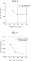
- a sliding test was carried out by rotating the rotating shaft 2 in a state in which a load was applied to a location 2 mm offset from the central portion 3AS along the shaft line O of the first region 3A toward the central portion 3BS along the shaft line O of the second region 3B in the oil-impregnated sintered bearing 10 shown in FIG. 1 , and the friction coefficient was computed.
- the measurement conditions are as described below.
- a preferred ratio of the area occupied by the Cu phase relative to the area of the inner circumferential surface S in the central portion 3AS of the first region 3A in the oil-impregnated sintered bearing 10 of the first embodiment shown in FIG. 1 was verified.
- the friction coefficients were measured.
- a sliding test was carried out by rotating the rotating shaft 2 in a state in which a load was applied to the central portion 3AS along the shaft line O of the first region 3A in the oil-impregnated sintered bearing 10 shown in FIG. 1 , and the friction coefficient was computed.
- the measurement conditions are as described below.
- an oil-impregnated sintered bearing having a taper angle ⁇ 1 of 0.1° was regarded as a sample 9
- an oil-impregnated sintered bearing having a taper angle ⁇ 1 of 4.0° was regarded as a sample 10.
- clearance was adjusted to accordingly accelerate sliding in the enlarged diameter portions.
- the clearance was set to approximately 10 ⁇ m in the sample 9 and set to approximately 70 ⁇ m in the sample 10.
- an oil-impregnated sintered bearing in which the taper angle ⁇ 1 was 0°, that is, the same bearing hole 3 as in the first embodiment has a straight tube shape was regarded as a sample 8 (comparative example).
- the samples 8 to 10 were formed by loading a powder mixture in which the mixing ratio was set to Fe-20 wt% Cu-2 wt% Sn into a cavity, sliding a core rod vertically in the cavity along the vertical direction, pressing upper and lower punches fitted into the cavity, and sintering the powder mixture.
- a sizing step was carried out so as to obtain the above-described taper angles, and shapes were imparted.
- the friction coefficients were measured.
- a sliding test was carried out by rotating the rotating shaft 2 in a state in which, in the oil-impregnated sintered bearing 20 (the oil-impregnated sintered bearing 10 shown in FIG. 1 for the sample 8) shown in FIG. 2 , a load was applied to a location 2 mm offset from the central portion 4AS (3AS) along the shaft line O of the first region 4A (3A) toward the central portion 4BS (3BS) along the shaft line O of the second region 4B (3B) and the core rod was slidden in the enlarged diameter portions 4b and 4c (for the samples 9 and 10), and the friction coefficient was computed.
- the measurement conditions are as described below.
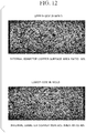
- FIG. 11 An enlarged photograph of the central portion 3BS along the shaft line O of the second region 3B and an enlarged photograph of the central portion 3CS along the shaft line O of the third region 3C in the bearing 10 shown in FIG. 1 are shown in FIG. 11 .
- FIG. 12 an enlarged photograph of a location corresponding to the central portion 3BS along the shaft line O of the second region 3B and an enlarged photograph of a location corresponding to the central portion 3CS along the shaft line O of the third region 3C in a bearing for which the core rod sliding step was not carried out and the disposition of the Cu foil pieces was not adjusted are shown in FIG. 12 .
- the shaped Up side of the upper drawing shows the central portion 3CS of the third region 3C
- the shaped Lo side of the lower drawing shows the central portion 3BS of the second region 3B.
- Bright portions in the enlarged photographs show the Cu phase.
- a powder mixture in which the mixing ratio was set to Fe-20 wt% Cu-2 wt% Sn was used.
- the core rod sliding step was carried out.
- the area ratio of the Cu phase in the central portion 3CS of the third region 3C that were present in the upper side during the shaping was 60%
- the area ratio of the Cu phase in the central portion 3BS of the second region 3B that were present in the lower side during the shaping was 55%. From this result, it is assumed that the Cu phase did not significantly change through the entire inner circumferential surface S of the bearing hole 4.
- the area ratio of the Cu phase in the central portion 3CS of the third region 3C that were present in the upper side during the shaping was 60%
- the area ratio of the Cu phase in the central portion 3BS of the second region 3B that were present in the lower side during the shaping was 40%. It was confirmed that the area ratios of the Cu phase significantly differed in the upper side and the lower side during the shaping in the inner circumferential surface S of the bearing hole 4.
Landscapes
- Engineering & Computer Science (AREA)
- General Engineering & Computer Science (AREA)
- Mechanical Engineering (AREA)
- Manufacturing & Machinery (AREA)
- Chemical & Material Sciences (AREA)
- Metallurgy (AREA)
- Materials Engineering (AREA)
- Organic Chemistry (AREA)
- Oil, Petroleum & Natural Gas (AREA)
- Sliding-Contact Bearings (AREA)
- Powder Metallurgy (AREA)
Applications Claiming Priority (2)
| Application Number | Priority Date | Filing Date | Title |
|---|---|---|---|
| JP2016204110A JP6864459B2 (ja) | 2016-10-18 | 2016-10-18 | 焼結含油軸受およびその製造方法 |
| PCT/JP2017/037704 WO2018074515A1 (ja) | 2016-10-18 | 2017-10-18 | 焼結含油軸受およびその製造方法 |
Publications (2)
| Publication Number | Publication Date |
|---|---|
| EP3530384A1 true EP3530384A1 (de) | 2019-08-28 |
| EP3530384A4 EP3530384A4 (de) | 2020-04-08 |
Family
ID=62019164
Family Applications (1)
| Application Number | Title | Priority Date | Filing Date |
|---|---|---|---|
| EP17862373.2A Withdrawn EP3530384A4 (de) | 2016-10-18 | 2017-10-18 | Ölimprägniertes gesintertes lager und herstellungsverfahren dafür |
Country Status (5)
| Country | Link |
|---|---|
| US (1) | US10731704B2 (de) |
| EP (1) | EP3530384A4 (de) |
| JP (1) | JP6864459B2 (de) |
| CN (1) | CN109689255B (de) |
| WO (1) | WO2018074515A1 (de) |
Family Cites Families (22)
| Publication number | Priority date | Publication date | Assignee | Title |
|---|---|---|---|---|
| JPH0819941B2 (ja) | 1987-07-23 | 1996-03-04 | 三菱マテリアル株式会社 | 焼結含油軸受 |
| JPH0294451U (de) | 1989-01-13 | 1990-07-26 | ||
| JPH06240301A (ja) * | 1993-02-12 | 1994-08-30 | Mikuni Corp | 粉体成形における粉体充填方法およびその装置 |
| JP3585693B2 (ja) * | 1993-12-28 | 2004-11-04 | 三菱マテリアル株式会社 | 焼結含油軸受 |
| JP2000240653A (ja) | 1999-02-24 | 2000-09-05 | Ntn Corp | 焼結含油軸受とその製造方法及び情報機器用スピンドルモータ |
| JP2004308682A (ja) | 2003-04-02 | 2004-11-04 | Mitsubishi Materials Corp | 焼結含油軸受 |
| JP2004308684A (ja) * | 2003-04-02 | 2004-11-04 | Mitsubishi Materials Corp | 焼結含油軸受 |
| EP1610011B1 (de) * | 2003-04-02 | 2019-06-12 | Diamet Corporation | Ölimprägniertes gesintertes lager und herstellungsverfahren dafür |
| JP4380274B2 (ja) * | 2003-09-10 | 2009-12-09 | 日立粉末冶金株式会社 | 鉄銅系焼結含油軸受用合金の製造方法 |
| JP4918967B2 (ja) * | 2005-04-20 | 2012-04-18 | 株式会社ダイヤメット | 摺動部品の製造方法 |
| JP6038522B2 (ja) * | 2012-07-24 | 2016-12-07 | Ntn株式会社 | 焼結軸受 |
| JP6114512B2 (ja) * | 2012-07-26 | 2017-04-12 | Ntn株式会社 | 焼結軸受およびその製造方法 |
| WO2014156856A1 (ja) * | 2013-03-25 | 2014-10-02 | Ntn株式会社 | 焼結軸受の製造方法、焼結軸受、およびそれを備えた振動モータ |
| EP3054185B1 (de) * | 2013-10-03 | 2024-02-21 | NTN Corporation | Herstellungsverfahren für ein gesintertes lager |
| WO2015050200A1 (ja) | 2013-10-03 | 2015-04-09 | Ntn株式会社 | 焼結軸受、およびその製造方法 |
| DE112016001226T5 (de) * | 2015-03-17 | 2017-11-30 | Ntn Corporation | Verfahren zum herstellen eines gesinterten lagers und gesintertes lager |
| JP6449059B2 (ja) | 2015-03-17 | 2019-01-09 | Ntn株式会社 | 焼結含油軸受およびその製造方法 |
| JP6456733B2 (ja) | 2015-03-17 | 2019-01-23 | Ntn株式会社 | 焼結軸受 |
| JP6625333B2 (ja) | 2015-03-17 | 2019-12-25 | Ntn株式会社 | 焼結軸受の製造方法および焼結軸受 |
| JP2016204110A (ja) | 2015-04-22 | 2016-12-08 | 佐藤工業株式会社 | 容器乾燥装置 |
| CN105312559A (zh) * | 2015-11-24 | 2016-02-10 | 重庆合达科技有限公司 | 耐磨含油轴承及其制造方法 |
| JP6240301B1 (ja) * | 2016-12-26 | 2017-11-29 | 株式会社コロプラ | 仮想空間を介して通信するための方法、当該方法をコンピュータに実行させるためのプログラム、および当該プログラムを実行するための情報処理装置 |
-
2016
- 2016-10-18 JP JP2016204110A patent/JP6864459B2/ja active Active
-
2017
- 2017-10-18 US US16/340,664 patent/US10731704B2/en active Active
- 2017-10-18 EP EP17862373.2A patent/EP3530384A4/de not_active Withdrawn
- 2017-10-18 CN CN201780054637.0A patent/CN109689255B/zh active Active
- 2017-10-18 WO PCT/JP2017/037704 patent/WO2018074515A1/ja not_active Ceased
Also Published As
| Publication number | Publication date |
|---|---|
| WO2018074515A1 (ja) | 2018-04-26 |
| JP2018066032A (ja) | 2018-04-26 |
| CN109689255B (zh) | 2021-06-25 |
| CN109689255A (zh) | 2019-04-26 |
| US10731704B2 (en) | 2020-08-04 |
| EP3530384A4 (de) | 2020-04-08 |
| US20200049198A1 (en) | 2020-02-13 |
| JP6864459B2 (ja) | 2021-04-28 |
Similar Documents
| Publication | Publication Date | Title |
|---|---|---|
| EP3396186B1 (de) | Gesintertes ölrückhaltelager und verfahren zur herstellung davon | |
| JP5247329B2 (ja) | 鉄系焼結軸受およびその製造方法 | |
| CN103221702B (zh) | 润滑特性提高的滑动轴承 | |
| US11219950B2 (en) | Sintered component | |
| EP2878839B1 (de) | Gesintertes lager und herstellungsverfahren davon | |
| EP3530384A1 (de) | Ölimprägniertes gesintertes lager und herstellungsverfahren dafür | |
| EP3278909A1 (de) | Kalibrierdüse zur verdichtung der oberfläche eines sinterkörpers, verfahren zur herstellung davon und fertigungsprodukt daraus | |
| EP1878521A1 (de) | Gleitteil und verfahren zu dessen herstellung | |
| US20160311026A1 (en) | Machine component using powder compact and method for producing same | |
| EP3534023B1 (de) | Ölimprägniertes gesintertes lager | |
| EP1872886A1 (de) | Gleitkomponente und verfahren zur herstellung derselben | |
| JP2006070940A (ja) | 円筒軸受ブッシュの製造方法 | |
| JP2008248975A (ja) | 焼結金属部品 | |
| JP2021088765A (ja) | 焼結含油軸受およびその製造方法 | |
| CN111566366A (zh) | 烧结含油轴承及其制造方法 | |
| JP2021088766A (ja) | 焼結含油軸受およびその製造方法 | |
| JP5276491B2 (ja) | 焼結体の表面緻密化方法 | |
| US6126710A (en) | Method of producing a sintered slide bearing and slide bearing | |
| WO2018100660A1 (ja) | 鉄系焼結含油軸受 | |
| JP6456733B2 (ja) | 焼結軸受 | |
| JP6625333B2 (ja) | 焼結軸受の製造方法および焼結軸受 | |
| JP2019052767A (ja) | 焼結軸受およびこれを備えた動力伝達機構 |
Legal Events
| Date | Code | Title | Description |
|---|---|---|---|
| STAA | Information on the status of an ep patent application or granted ep patent |
Free format text: STATUS: THE INTERNATIONAL PUBLICATION HAS BEEN MADE |
|
| PUAI | Public reference made under article 153(3) epc to a published international application that has entered the european phase |
Free format text: ORIGINAL CODE: 0009012 |
|
| STAA | Information on the status of an ep patent application or granted ep patent |
Free format text: STATUS: REQUEST FOR EXAMINATION WAS MADE |
|
| 17P | Request for examination filed |
Effective date: 20190412 |
|
| AK | Designated contracting states |
Kind code of ref document: A1 Designated state(s): AL AT BE BG CH CY CZ DE DK EE ES FI FR GB GR HR HU IE IS IT LI LT LU LV MC MK MT NL NO PL PT RO RS SE SI SK SM TR |
|
| AX | Request for extension of the european patent |
Extension state: BA ME |
|
| DAV | Request for validation of the european patent (deleted) | ||
| DAX | Request for extension of the european patent (deleted) | ||
| A4 | Supplementary search report drawn up and despatched |
Effective date: 20200306 |
|
| RIC1 | Information provided on ipc code assigned before grant |
Ipc: B22F 5/10 20060101ALI20200302BHEP Ipc: F16C 33/12 20060101ALI20200302BHEP Ipc: B22F 5/00 20060101AFI20200302BHEP Ipc: F16C 23/04 20060101ALI20200302BHEP Ipc: B22F 1/00 20060101ALI20200302BHEP Ipc: F16C 33/14 20060101ALI20200302BHEP Ipc: C22C 33/02 20060101ALI20200302BHEP Ipc: F16C 33/10 20060101ALI20200302BHEP Ipc: B22F 3/26 20060101ALI20200302BHEP Ipc: B22F 3/24 20060101ALI20200302BHEP Ipc: B22F 3/035 20060101ALI20200302BHEP Ipc: F16C 17/02 20060101ALI20200302BHEP |
|
| STAA | Information on the status of an ep patent application or granted ep patent |
Free format text: STATUS: EXAMINATION IS IN PROGRESS |
|
| 17Q | First examination report despatched |
Effective date: 20201117 |
|
| GRAP | Despatch of communication of intention to grant a patent |
Free format text: ORIGINAL CODE: EPIDOSNIGR1 |
|
| STAA | Information on the status of an ep patent application or granted ep patent |
Free format text: STATUS: GRANT OF PATENT IS INTENDED |
|
| INTG | Intention to grant announced |
Effective date: 20210707 |
|
| STAA | Information on the status of an ep patent application or granted ep patent |
Free format text: STATUS: THE APPLICATION IS DEEMED TO BE WITHDRAWN |
|
| 18D | Application deemed to be withdrawn |
Effective date: 20211118 |