EP3530393A1 - Sägeblatt mit schub- und zugverzahnung - Google Patents
Sägeblatt mit schub- und zugverzahnung Download PDFInfo
- Publication number
- EP3530393A1 EP3530393A1 EP19156192.7A EP19156192A EP3530393A1 EP 3530393 A1 EP3530393 A1 EP 3530393A1 EP 19156192 A EP19156192 A EP 19156192A EP 3530393 A1 EP3530393 A1 EP 3530393A1
- Authority
- EP
- European Patent Office
- Prior art keywords
- angle
- toothing
- teeth
- saw blade
- tooth
- Prior art date
- Legal status (The legal status is an assumption and is not a legal conclusion. Google has not performed a legal analysis and makes no representation as to the accuracy of the status listed.)
- Granted
Links
Images


Classifications
-
- B—PERFORMING OPERATIONS; TRANSPORTING
- B23—MACHINE TOOLS; METAL-WORKING NOT OTHERWISE PROVIDED FOR
- B23D—PLANING; SLOTTING; SHEARING; BROACHING; SAWING; FILING; SCRAPING; LIKE OPERATIONS FOR WORKING METAL BY REMOVING MATERIAL, NOT OTHERWISE PROVIDED FOR
- B23D61/00—Tools for sawing machines or sawing devices; Clamping devices for these tools
- B23D61/12—Straight saw blades; Strap saw blades
- B23D61/121—Types of set; Variable teeth, e.g. variable in height or gullet depth; Varying pitch; Details of gullet
-
- B—PERFORMING OPERATIONS; TRANSPORTING
- B23—MACHINE TOOLS; METAL-WORKING NOT OTHERWISE PROVIDED FOR
- B23D—PLANING; SLOTTING; SHEARING; BROACHING; SAWING; FILING; SCRAPING; LIKE OPERATIONS FOR WORKING METAL BY REMOVING MATERIAL, NOT OTHERWISE PROVIDED FOR
- B23D61/00—Tools for sawing machines or sawing devices; Clamping devices for these tools
- B23D61/12—Straight saw blades; Strap saw blades
- B23D61/128—Sabre saw blades
Definitions
- the invention relates to a saw blade, each with a pointing to a first end, inclined at a first angle to a direction perpendicular to the extension direction of the saw blade first tooth flank and pointing to a second end, inclined at a second angle to the vertical line second tooth flank teeth, the in a first end adjacent the impact toothing, in which the first angle are greater than the second angle, and which are arranged in a second end adjacent the Switzerlandveriereung, in which the first angle are smaller than the second angle.
- Such saw blades are known in the art and are used as jigsaw blades to saw kitchen countertops. At the hinge of the saw blade adjoins a shock gearing. A serration adjoins the tip of the saw blade so that the cutting direction always takes place into the workpiece. Saw blades with teeth toothed in two different directions are known from the US 2003/0 010 179 A1 . WO 2008/106 425 A2 and DE 37 06 429 A1 ,
- the invention has for its object to improve the generic saw blade in terms of use schne.vorges advantage advantage, in particular the task is to produce a cut with a smooth cutting edge.
- a saw blade with preferably ground teeth in which a shock toothing is arranged at a first end, in particular the end, which is provided with a fishing rod.
- the teeth have a tooth flank pointing in the impact direction, which is inclined at a more acute angle relative to a reference line which runs perpendicular to the direction of extension of the saw blade, as a second tooth flank pointing away from it.
- the adjoining the opposite end, for example, the tip of the saw blade arranged Switzerland has a mirror-image toothing on.
- the cutting edges pointing in the pulling direction are inclined at an acute angle to a reference line running perpendicular to the direction of extension, as the tooth flanks pointing towards the tip.
- this neutral toothing at least some teeth are arranged, whose tooth flanks pointing in the direction of impact have a greater angle of inclination than the teeth of the impact toothing and their tooth flanks pointing in the pulling direction have a greater inclination angle than the tooth flanks of the teeth of the tensile toothing pointing in the pulling direction.
- the first angles of the teeth gradually decrease from the first end to the second end.
- the second angles of the teeth may gradually increase from the first end to the second end.
- the teeth immediately adjacent to the respective ends have cutting edges with the least inclination to a perpendicular to the direction of extension and thus provide the greatest cutting performance.
- the lowest cutting power is provided by the teeth of the neutral zone.
- These essentially have the function of broaching teeth.
- There may also be arranged one or more teeth in which the first and second tooth flanks have the same angle to a direction perpendicular to the extending direction reference line.
- the first tooth flanks of the between the first end and the second end disposed teeth thus have a decreasing first angle toward the second end.
- the second tooth flanks of the teeth disposed between the first end and the second end have an increasing second angle toward the second end.
- first angle or the second angle of the first and second tooth flank of adjacent teeth are different from each other.
- first and second tooth flanks are inclined such that an angle bisector between the first tooth flank and the second tooth flank of at least some of the teeth intersect at a point or in a surface surrounding a point, in particular a circular surface.
- the bisectors of all teeth intersect at a point or a surface surrounding a point, the diameter of such a circular area corresponds to a maximum of a quarter of the length of the total toothing, as the length of the total teeth, the distance between the, the first end on nearest tooth to the tooth closest to the second end.
- the area in which intersect the bisecting lines of all teeth may be a circular area with a maximum of one-eighth of the length of the overall toothing.
- the teeth are preferably ground teeth.
- each tooth flank of a tooth can form a cutting edge, wherein the cutting edges adjoin phases and the phases adjacent to the two cutting edges of a tooth are roof-like in the tooth tip region, so that a boundary line pointing in the direction of the bisecting line is formed between the two phases.
- the tips of the teeth run on a curved line. It may preferably be a concave arc line that forms a constriction in the saw blade.
- the arc line can be a circular arc line.
- the radius of the arc is greater than the total length of the gearing.
- the center of the arc line is preferably on the toothing having side of the saw blade.
- the intersection of the bisectors is understood to mean a surface within which the total number of intersection points of the bisectors of all teeth of the toothing lies. The point of intersection is, so to speak, formed by the center of a circle in which all bisectors intersect. The intersection has a distance to the toothing that is smaller than the radius of the arc line.
- the circular area around the point of intersection, in which intersect the bisectors has a maximum diameter of half, preferably a maximum of one quarter of the total length of the toothing.
- the second end of the saw blade is preferably formed by the tip of a jigsaw blade whose first end is a tang with which the jigsaw blade can be mounted in a drive unit.
- Jigsaw blades are known from the prior art, which have a toothing on their chest.
- the toothing extends from a first end 1, namely a fishing rod, to a second end 2, namely a point.
- the toothing consists of an adjacent to the fishing rod toothing and adjacent to the tip of the toothing.
- the teeth of the toothing have two tooth flanks. A first tooth flank is directed to the first end. A second tooth flank is directed to the second end.
- an imaginary line extending along the toothing, ie from the first end to the second end.
- To characterize the teeth of the teeth angles are used, which occupy the tooth flanks to a reference line 18, wherein the reference line 18 is a vertical line to the extension direction. fixed tooth angle, however, which are aligned approximately in folding symmetry to those of the impact gear 3.
- Each tooth of the impact toothing 3 and each tooth of the toothed train 4 thus each has the same tooth and rake angle.
- toothing 3 In the toothing 3, the first angle ⁇ , the first tooth flank 7 assumes the reference line 18, greater than the second angle ⁇ , the second tooth flank 8 occupies the reference line 18, so that the direction away from the Angel second tooth flank 8 here is cutting edge.
- the first angle ⁇ of the first tooth flank 10 In the area of the traction toothing 4 adjacent the second end 2, the first angle ⁇ of the first tooth flank 10 is smaller than the second angle ⁇ of the tooth flank 11, so that here the cutting cutting edge is directed away from the second end 2.
- toothing 4 and 3 toothing - are arranged in a symmetrical manner with respect to a symmetry line. There, each tooth of the impact gear 3 and each tooth of the toothed train 4 each have the same tooth angle or rake angle.
- the impact toothing 3 and the toothed tooth system 4 have a sequence of tooth sequences deviating from the prior art. It is worked with a pointed tooth, which has no fixed alignment of its tooth flanks.
- the toothing is a ground toothing, which has three Unterveriereept.
- Tusks 6, which have a first tooth flank 7 facing the first end formed by the tang, are arranged in a shock toothing 3 adjacent to the tang.
- the first tooth flanks 7 have a first inclination angle ⁇ 1 to a reference line 18 running perpendicular to the extension line.
- a second tooth flank 8 meeting in a tooth tip 6 'with the first tooth flank 7 has a second inclination angle ⁇ 1 to the reference line 18, the first inclination angle ⁇ 1 is greater than the second inclination angle ⁇ 1.
- the second inclination angle ⁇ 1 here is about 14 degrees.
- the first tooth flank 10 has an inclination angle a2 to the reference line 18, which is smaller than the inclination angle ⁇ 2 a second tooth flank 11, which faces the second end 2, which of a Tip of the jigsaw blade is formed.
- the first inclination angle a2 of the first tooth flank 10 pointing towards the first end 1 is here about 1 degree.
- a neutral toothing 5 is located approximately in the middle of the total toothing between the toothing 3 and the toothing 4, in which the first tooth flanks 13 cutting in a tooth tip 12 'have a first angle of inclination ⁇ 3 to a perpendicular 8 to the direction of extent, which is smaller than
- the second inclination angle ⁇ 3 of the second tooth flank 14 facing the tip 2 is greater than the second inclination angle ⁇ 1 of the first tooth flanks in the impact gear 3 and smaller than the second inclination angle ⁇ 2 of the second tooth flanks 11 in the toothed train 4th
- the inclination angles ⁇ , ⁇ of two adjacent teeth are different from each other. Beginning with the teeth 6 adjacent to the first end 1, the second angle of inclination ⁇ in each tooth following in the direction of the second end 2 increases until the angle of inclination ⁇ reaches its maximum at the tooth 9 immediately adjacent to the second end 2.
- the first inclination angle ⁇ has its maximum at the first end 1 immediately adjacent tooth 6 and decreases gradually from follower tooth to follower tooth to the second end 2 immediately adjacent tooth 9, where the first inclination angle a2 has its minimum.
- the total toothing thus has successive teeth, in which the angle of the tooth flanks to a reference line changes gradually in the same direction from tooth to tooth.
- the intersection of this guide is offset from the center of the toothing to the first end (the tang).
- the tooth tips 6 ', 9', 12 ' lie on a curved line 16.
- the center M1 of this arc line 16 lies on the same side of the saw blade, on which the intersection of the bisecting line 15 is located. But it is further spaced from the saw blade, as the intersection, namely about 1300 mm (radius R1).
- the arc line 16 thus defines a constriction. This avoids that in thinner workpieces 17 in the top 17 'plunging teeth a cutting effect in the bottom 17 "has or dipping into the bottom 17 traction teeth has a cutting action on the top 17' has.
- a five-axis milling machine is preferably provided with which the tooth flanks 7, 8, 10, 11, 13, 14 are manufactured in a varying arrangement.
- a saw blade which is characterized in that teeth 12, which are arranged in a lying between the toothing 3 and the toothing teeth 4 neutral toothing 5, each having a first tooth flank 13 having a first angle ⁇ 3 to the vertical line 18, which is smaller than that first angle ⁇ of the impact gear 2 and is greater than the first angle ⁇ 2 of the Switzerlandverzahnung, and a second tooth flank 14 have at a second angle ⁇ 3 to the vertical line 18, which is greater than the second angle ⁇ 1 of the impact gear 3 and is smaller than that second angle ⁇ 2 of the toothed train 4th
- a saw blade which is characterized in that the first tooth flanks 7, 10, 13 of the teeth 6, 9, 12 arranged between the first end 1 and the second end 2 gradually decrease in the direction of the second end 2, first angle ⁇ 1, ⁇ 2, ⁇ 3 and / or that the second tooth flanks 8, 11, 14 arranged between the first end 1 and the second end 2 Teeth 6, 9, 12 in the direction of the second end 2 gradually increasing second angle ⁇ 1, ⁇ 2, ⁇ 3 have.
- a saw blade which is characterized in that the first angle ⁇ 1, ⁇ 2, ⁇ 3 of the first tooth flanks 7, 10, 13 to the vertical line 18 of adjacent teeth are different from each other and / or that the second angle ⁇ 1, ⁇ 2, ⁇ 3 of the second tooth flanks eighth , 11, 14 of adjacent teeth 6, 9, 12 are different from one another.
- a saw blade which is characterized in that the bisectors 15 intersect each other between the first tooth flank 7, 10, 13 and second tooth flank 8, 11, 14 of at least some of the teeth 6, 9, 12 at a point or in a surface surrounding the point and / or that all bisectors 15 intersect at a point or a surface surrounding the point, wherein the diameter of a circle forming the surface is not greater than a quarter of the length of the total toothing.
- a saw blade which is characterized in that the tips 6 ', 9', 12 'of the teeth 6, 9, 12 extend on a curved line 16 and / or that the curved line 16 runs concave and / or a circular arc line with a radius R1 which is larger than the total length of the gearing.
- a saw blade which is characterized in that the intersection of the bisecting line 15 or the center of the cut surface has a distance R2 to the toothing, which is smaller than the radius R1 of the arc line sixteenth
- a saw blade which is characterized in that a line drawn perpendicular to the extension direction through the center point M1 of the arcuate line 16 lies approximately centrally between the ends of the overall toothing.
- a saw blade which is characterized in that the point of intersection of the bisecting line 15 or the center point M2 of a sectional area offset from the first or second end lies off-center of the overall toothing.
- the invention also relates to design forms in which individual of the features mentioned in the above description are not realized, in particular insofar as they are recognizable dispensable for the respective purpose or can be replaced by other technically equivalent means.
- ⁇ b> ⁇ u> List of Reference Numbers ⁇ / u> ⁇ /b> 1 first end ⁇ 1 first angle 2 second end ⁇ 2 first angle 3 shock teeth ⁇ 3 first angle 4
- Gyveriereung ⁇ 1 second angle 5 neutral teeth
Landscapes
- Engineering & Computer Science (AREA)
- Mechanical Engineering (AREA)
- Sawing (AREA)
- Gears, Cams (AREA)
- Knives (AREA)
Abstract
Description
- Die Erfindung betrifft ein Sägeblatt mit jeweils eine zu einem ersten Ende weisende, in einem ersten Winkel zu einer zur Erstreckungsrichtung des Sägeblattes senkrechten Linie geneigten ersten Zahnflanke und eine zu einem zweiten Ende weisende, in einem zweiten Winkel zur senkrechten Linie geneigten zweiten Zahnflanke aufweisenden Zähnen, die in einer dem ersten Ende benachbarten Stoßverzahnung, in der die ersten Winkel größer sind als die zweiten Winkel, und die in einer dem zweiten Ende benachbarten Zugverzahnung angeordnet sind, in der die ersten Winkel kleiner sind als die zweiten Winkel.
- Derartige Sägeblätter sind im Stand der Technik bekannt und werden als Stichsägeblätter verwendet, um Küchenarbeitsplatten zu sägen. An die Angel des Sägeblattes grenzt eine Stoßverzahnung an. An die Spitze des Sägeblattes grenzt eine Zugverzahnung an, so dass die Zerspanrichtung immer ins Werkstück hinein erfolgt. Sägeblätter mit in zwei verschiedenen Richtungen verzahnten Sägezähnen sind bekannt aus den
US 2003 / 0 010 179 A1 ,WO 2008 / 106 425 A2 undDE 37 06 429 A1 . - Der Erfindung liegt die Aufgabe zugrunde, das gattungsgemäße Sägeblatt hinsichtlich seines Schneiderfolges gebrauchsvorteilhaft zu verbessern, wobei insbesondere die Aufgabe besteht, einen Schnitt mit einer glatten Schnittkante zu erzeugen.
- Zunächst und im Wesentlichen wird ein Sägeblatt mit bevorzugt geschliffenen Zähnen vorgeschlagen, bei dem an einem ersten Ende, insbesondere dem Ende, das mit einer Angel versehen ist, eine Stoßverzahnung angeordnet ist. Bei einem derartig ausgebildeten Sägeblatt, insbesondere Stichsägeblatt besitzen die Zähne eine in Stoßrichtung weisende Zahnflanke, die bezogen auf eine Bezugslinie, die senkrecht zur Erstreckungsrichtung des Sägeblattes verläuft, spitzwinkliger geneigt ist, als eine davon wegweisende zweite Zahnflanke. Die angrenzend an das gegenüberliegende Ende, beispielsweise der Spitze des Sägeblattes, angeordnete Zugverzahnung weist eine dazu spiegelbildliche Verzahnung auf. Die in Zugrichtung weisenden Schneidflanken sind spitzwinkliger zu einer senkrecht zur Erstreckungsrichtung verlaufenden Bezugslinie geneigt, als die zur Spitze weisenden Zahnflanken. Erfindungsgemäß befindet sich zwischen der Stoßverzahnung und der Zugverzahnung eine Neutralverzahnung. In dieser Neutralverzahnung sind zumindest einige Zähne angeordnet, deren in Stoßrichtung weisende Zahnflanken einen größeren Neigungswinkel aufweisen, als die Zähne der Stoßverzahnung und deren in Zugrichtung weisende Zahnflanken einen größeren Neigungswinkel aufweisen, als die in Zugrichtung weisenden Zahnflanken der Zähne der Zugverzahnung. In einer Weiterbildung der Erfindung wird vorgeschlagen, dass sich die ersten Winkel der Zähne vom ersten Ende hin zum zweiten Ende schrittweise verkleinern. Alternativ oder ergänzend dazu können sich die zweiten Winkel der Zähne vom ersten Ende zum zweiten Ende schrittweise vergrößern. Dies hat zur Folge, dass die den jeweiligen Enden unmittelbar benachbarten Zähne Schneidkanten mit der geringsten Neigung zu einer Senkrechten zur Erstreckungsrichtung aufweisen und damit die größte Schneidleistung erbringen. Die geringste Schneidleistung wird von den Zähnen der Neutralzone erbracht. Diese haben im Wesentlichen die Funktion von Räumzähnen. Dort können auch ein oder mehrere Zähne angeordnet sein, bei denen die ersten und zweiten Zahnflanken denselben Winkel zu einer senkrecht zur Erstreckungsrichtung verlaufenden Bezugslinie aufweisen. Die ersten Zahnflanken der zwischen dem ersten Ende und dem zweiten Ende angeordneten Zähne haben somit in Richtung zum zweiten Ende einen abnehmenden ersten Winkel. Die zweiten Zahnflanken der zwischen dem ersten Ende und dem zweiten Ende angeordneten Zähne haben in Richtung zum zweiten Ende einen zunehmenden zweiten Winkel. In einer Weiterbildung der Erfindung ist vorgesehen, dass die ersten Winkel beziehungsweise die zweiten Winkel der ersten beziehungsweise zweiten Zahnflanke benachbarter Zähne voneinander verschieden sind. Eine vorteilhafte Weiterbildung besteht darin, dass die ersten und zweiten Zahnflanken derart geneigt sind, dass eine Winkelhalbierende zwischen der ersten Zahnflanke und der zweiten Zahnflanke zumindest einiger der Zähne sich in einem Punkt oder in einer einen Punkt umgebenden Fläche, insbesondere Kreisfläche schneiden. Gemäß einer besonders bevorzugten Ausgestaltung schneiden sich die Winkelhalbierenden aller Zähne in einem Punkt beziehungsweise einer einen Punkt umgebenden Fläche, wobei der Durchmesser einer derartigen Kreisfläche maximal einem Viertel der Länge der Gesamtverzahnung entspricht, wobei als Länge der Gesamtverzahnung die Strecke zwischen dem, dem ersten Ende am nächsten liegenden Zahn zu dem, dem zweiten Ende am nächsten liegenden Zahn verstanden wird. Die Fläche, in der sich gemäß einem Ausführungsbeispiel der Erfindung die Winkelhalbierenden aller Zähne schneiden, kann eine Kreisfläche mit maximal einem Achtel der Länge der Gesamtverzahnung sein. Bei den Zähnen handelt es sich bevorzugt um geschliffene Zähne. Bevorzugt kann jede Zahnflanke eines Zahnes eine Schneidkante ausbilden, wobei die Schneidkanten an Phasen angrenzen und die an die beiden Schneidkanten eines Zahnes angrenzenden Phasen im Zahnspitzenbereich dachartig zueinander stehen, sodass sich eine in Richtung der Winkelhalbierenden weisenden Begrenzungslinie zwischen den beiden Phasen ausbildet. In einer bevorzugten Weiterbildung der Erfindung wird vorgeschlagen, dass die Spitzen der Zähne auf einer Bogenlinie verlaufen. Es kann sich bevorzugt um eine konkave Bogenlinie handeln, die eine Einschnürung in das Sägeblatt formt. Die Bogenlinie kann eine Kreisbogenlinie sein. Der Radius der Kreisbogenlinie ist größer als die Gesamtlänge der Verzahnung. Der Mittelpunkt der Bogenlinie liegt bevorzugt auf der die Verzahnung aufweisenden Seite des Sägeblattes. Unter dem Schnittpunkt der Winkelhalbierenden wird eine Fläche verstanden, innerhalb der die Gesamtzahl der Schnittpunkte der Winkelhalbierenden aller Zähne der Verzahnung liegt. Der Schnittpunkt wird gewissermaßen von dem Mittelpunkt eines Kreises gebildet, in dem sich alle Winkelhalbierenden schneiden. Der Schnittpunkt hat einen Abstand zur Verzahnung, der kleiner ist, als der Radius der Bogenlinie. Die Kreisfläche um den Schnittpunkt, in dem sich die Winkelhalbierenden schneiden, hat einen Durchmesser von maximal der Hälfte, bevorzugt maximal einem Viertel der Gesamtlänge der Verzahnung. Zieht man durch den Mittelpunkt der Bogenlinie eine Senkrechte zur Erstreckungsrichtung des Sägeblattes, so schneidet diese Senkrechte das Sägeblatt etwa mittig der Verzahnung. Zieht man eine Senkrechte zur Erstreckungsrichtung des Sägeblattes durch den Schnittpunkt der Winkelhalbierenden, so schneidet diese Senkrechte das Sägeblatt an einer Position, die aus der Mitte versetzt ist. Bevorzugt ist der Schnittpunkt von der Mitte zum ersten Ende hin versetzt. Das zweite Ende des Sägeblattes wird bevorzugt von der Spitze eines Stichsägeblattes gebildet, dessen erstes Ende eine Angel ist, mit der das Stichsägeblatt in einem Antriebsgerät befestigt werden kann.
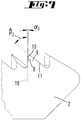
- Ein Ausführungsbeispiel der Erfindung wird nachfolgend anhand beigefügter Zeichnungen erläutert. Es zeigen:
- Fig. 1
- eine perspektivische Darstellung des Sägeblattes,
- Fig. 2
- eine Funktionsstellung des Sägeblattes,
- Fig. 3
- eine Draufsicht auf das Sägeblatt,
- Fig. 4
- eine spiegelbildliche Darstellung gemäß
Figur 3 zur Verdeutlichung der Lagen der Stoßverzahnung 3, Zugverzahnung 4 und Neutralverzahnung 5, - Fig. 5
- den Ausschnitt V in
Figur 4 im Bereich der Stoßverzahnung 3, - Fig. 6
- den Ausschnitt VI in
Figur 4 im Bereich der Neutralverzahnung 5 und - Fig. 7
- den Ausschnitt VII in
Figur 4 im Bereich der Zugverzahnung 4, - Aus dem Stand der Technik sind Stichsägeblätter bekannt, die auf ihrer Brust eine Verzahnung aufweisen. Die Verzahnung erstreckt sich von einem ersten Ende 1, nämlich einer Angel, bis zu einem zweiten Ende 2, nämlich einer Spitze. Die Verzahnung besteht aus einer an die Angel angrenzenden Stoßverzahnung und einer an die Spitze angrenzenden Zugverzahnung. Die Zähne der Verzahnung besitzen zwei Zahnflanken. Eine erste Zahnflanke ist zum erstens Ende gerichtet. Eine zweite Zahnflanke ist zum zweiten Ende gerichtet. Unter Erstreckungsrichtung des Sägeblattes wird erfindungsgemäß eine gedachte Linie verstanden, die sich entlang der Verzahnung, also vom ersten Ende zum zweiten Ende erstreckt. Zur Charakterisierung der Zähne der Verzahnung werden Winkel verwendet, die die Zahnflanken zu einer Bezugslinie 18 einnehmen, wobei die Bezugslinie 18 eine senkrechte Linie zur Erstreckungsrichtung ist. fixe Zahnwinkel, die jedoch in etwa klappsymmetrisch zu denen der Stoßverzahnung 3 ausgerichtet sind. Jeder Zahn der Stoßverzahnung 3 und jeder Zahn der Zugverzahnung 4 hat somit jeweils den gleichen Zahn- und Spanwinkel.
- In der Stoßverzahnung 3 ist der erste Winkel α, den die erste Zahnflanke 7 zur Bezugslinie 18 einnimmt, größer, als der zweite Winkel β, den die zweite Zahnflanke 8 zur Bezugslinie 18 einnimmt, so dass die von der Angel wegweisende zweite Zahnflanke 8 hier die spanabhebende Schneidkante ist. Im Bereich der dem zweiten Ende 2 benachbarten Zugverzahnung 4 ist der erste Winkel α der ersten Zahnflanke 10 kleiner als der zweite Winkel β der Zahnflanke 11, so dass hier die zerspanende Schneidkante von dem zweiten Ende 2 weggerichtet ist. Beim Stand der Technik sind Zugverzahnung 4 und Stoßverzahnung 3 - bezogen auf eine Symmetrielinie, klappsymmetrisch angeordnet. Dort hat jeder Zahn der Stoßverzahnung 3 und jeder Zahn der Zugverzahnung 4 jeweils den gleichen Zahnwinkel beziehungsweise Spanwinkel.
- Erfindungsgemäß weist die Stoßverzahnung 3 und die Zugverzahnung 4 eine vom Stand der Technik abweichende Zahnfolgen-Gestaltung auf. Es wird mit einem Spitzzahn gearbeitet, der keine fixe Ausrichtung seiner Zahnflanken besitzt.
- Bei der Verzahnung handelt es sich um eine geschliffene Verzahnung, die drei Unterverzahnungen aufweist. In einer an die Angel angrenzenden Stoßverzahnung 3 sind Stoßzähne 6 angeordnet, die eine erste Zahnflanke 7 aufweisen, die zu dem von der Angel gebildeten ersten Ende weisen. Die ersten Zahnflanken 7 haben einen ersten Neigungswinkel α1 zu einer senkrecht zur Erstreckungslinie verlaufenden Bezugslinie 18. Eine zweite Zahnflanke 8, die sich in einer Zahnspitze 6' mit der ersten Zahnflanke 7 trifft, hat einen zweiten Neigungswinkel β1 zur Bezugslinie 18, wobei der erste Neigungswinkel α1 größer ist, als der zweite Neigungswinkel β1. Der zweite Neigungswinkel β1 beträgt hier etwa 14 Grad.
- In einer dem zweiten Ende 2 benachbarten Zugverzahnung 4 sind Zugzähne 9 angeordnet, deren erste Zahnflanke 10 einen Neigungswinkel a2 zur Bezugslinie 18 aufweist, der kleiner ist, als der Neigungswinkel β2 einer zweiten Zahnflanke 11, die zum zweiten Ende 2 hin weist, welche von einer Spitze des Stichsägeblattes gebildet ist. Der erste Neigungswinkel a2 der zum ersten Ende 1 hin weisenden ersten Zahnflanke 10 beträgt hier etwa 1 Grad.
- Zwischen der Stoßverzahnung 3 und der Zugverzahnung 4 befindet sich etwa in der Mitte der Gesamtverzahnung eine Neutralverzahnung 5, bei der sich die in einer Zahnspitze 12' schneidenden ersten Zahnflanken 13 einen ersten Neigungswinkel α3 zu einer Senkrechten 8 zur Erstreckungsrichtung besitzen, der kleiner ist, als der erste Neigungswinkel α1 in der Stoßverzahnung 3 und größer ist, als der erste Neigungswinkel a2 in der Zugverzahnung 4. Der zweite Neigungswinkel β3 der zweiten Zahnflanke 14, die zur Spitze 2 weist, ist größer als der zweite Neigungswinkel β1 der ersten Zahnflanken in der Stoßverzahnung 3 und kleiner als der zweite Neigungswinkel β2 der zweiten Zahnflanken 11 in der Zugverzahnung 4.
- Beim Ausführungsbeispiel sind die Neigungswinkel α, β zweier benachbarter Zähne voneinander verschieden. Beginnend mit den dem ersten Ende 1 benachbarten Zähnen 6 vergrößert sich der zweite Neigungswinkel β bei jedem in Richtung auf das zweite Ende 2 folgenden Zahn, bis der Neigungswinkel β an dem dem zweiten Ende 2 unmittelbar benachbarten Zahn 9 sein Maximum erreicht. Der erste Neigungswinkel α hat hingegen bei dem dem ersten Ende 1 unmittelbar benachbarten Zahn 6 sein Maximum und verkleinert sich schrittweise von Folgezahn zu Folgezahn bis zu dem dem zweiten Ende 2 unmittelbar benachbarten Zahn 9, wo der erste Neigungswinkel a2 sein Minimum besitzt. Die Gesamtverzahnung besitzt somit aufeinanderfolgende Zähne, bei denen sich der Winkel der Zahnflanken zu einer Bezugslinie schrittweise gleichsinnig von Zahn zu Zahn verändert.
- Zieht man durch die Spitzen 6', 9', 12' der Zähne 6, 9, 12 jeweils eine Winkelhalbierende 15 zu den jeweils ersten und zweiten Zahnflanken 7, 8; 10, 11; 13, 14, so schneiden sich die Winkelhalbierenden 15 innerhalb einer kleinen Fläche, beispielsweise einer Kreisfläche. Der Mittelpunkt M2 dieser Fläche kann als Schnittpunkt der Winkelhalbierenden 15 betrachtet werden. Der Abstand R2 dieses Mittelpunktes M2 von den Zahnspitzen 6', 9', 12' beträgt etwa 170 mm.
- Eine senkrecht zur Erstreckungsrichtung des Sägeblattes verlaufende Hilfslinie, die durch diesen Schnittpunkt hindurchgeht, schneidet die Verzahnung außermittig. Der Schnittpunkt dieser Hilfslinie liegt von der Mitte der Verzahnung hin zum ersten Ende (der Angel) versetzt.
- Die Zahnspitzen 6', 9', 12' liegen auf einer Bogenlinie 16. Der Mittelpunkt M1 dieser Bogenlinie 16 liegt auf derselben Seite des Sägeblattes, auf dem auch der Schnittpunkt der Winkelhalbierenden 15 liegt. Er ist aber weiter von dem Sägeblatt beabstandet, als der Schnittpunkt, nämlich etwa 1.300 mm (Radius R1).
- In Bezug auf den geradlinig verlaufenden Blattrücken definiert die Bogenlinie 16 somit eine Einschnürung. Hierdurch wird vermieden, dass bei dünneren Werkstücken 17 die in die Oberseite 17' eintauchende Stoßverzahnung eine spanabhebende Wirkung im Bereich der Unterseite 17" besitzt beziehungsweise die in die Unterseite 17 eintauchende Zugverzahnung eine spanabhebende Wirkung an der Oberseite 17' besitzt.
- Zufolge der variierenden Zahnform wird mit dem erfindungsgemäßen Sägeblatt ein extrem sauberer Schnitt auf beiden Seiten eines Werkstücks erreicht, da Ausrisse vermieden werden.
- Zur Fertigung derartiger Sägeblätter wird bevorzugt eine Fünfachs-Fräsanlage vorgesehen, mit der die Zahnflanken 7, 8, 10, 11, 13, 14 in variierender Anordnung gefertigt werden.
- Die vorstehenden Ausführungen dienen der Erläuterung der von der Anmeldung insgesamt erfassten Erfindungen, die den Stand der Technik zumindest durch die folgenden Merkmalskombinationen jeweils auch eigenständig weiterbilden, wobei zwei, mehrere oder alle dieser Merkmalskombinationen auch kombiniert sein können, nämlich:
- Ein Sägeblatt, das dadurch gekennzeichnet ist, dass Zähne 12, die in einer zwischen der Stoßverzahnung 3 und der Zugverzahnung 4 liegenden Neutralverzahnung 5 angeordnet sind, jeweils eine erste Zahnflanke 13 aufweisen mit einem ersten Winkel α3 zur senkrechten Linie 18, der kleiner ist als die ersten Winkel α der Stoßverzahnung 2 und größer ist als die ersten Winkel α2 der Zugverzahnung, und eine zweite Zahnflanke 14 aufweisen mit einem zweiten Winkel β3 zur senkrechten Linie 18, der größer ist als die zweiten Winkel β1 der Stoßverzahnung 3 und kleiner ist, als die zweiten Winkel β2 der Zugverzahnung 4.
- Ein Sägeblatt, das dadurch gekennzeichnet ist, dass die ersten Zahnflanken 7, 10, 13 der zwischen dem ersten Ende 1 und dem zweiten Ende 2 angeordneten Zähne 6, 9, 12 in Richtung zum zweiten Ende 2 schrittweise abnehmende erste Winkel α1, α2, α3 aufweisen und/oder dass die zweiten Zahnflanken 8, 11, 14 der zwischen dem ersten Ende 1 und dem zweiten Ende 2 angeordneten Zähne 6, 9, 12 in Richtung zum zweiten Ende 2 schrittweise größer werdende zweite Winkel β1, β2, β3 aufweisen.
- Ein Sägeblatt, das dadurch gekennzeichnet ist, dass die ersten Winkel α1, α2, α3 der ersten Zahnflanken 7, 10, 13 zur senkrechen Linie 18 benachbarter Zähne voneinander verschieden sind und/oder dass die zweiten Winkel β1, β2, β3 der zweiten Zahnflanken 8,11,14 benachbarter Zähne 6, 9, 12 voneinander verschieden sind.
- Ein Sägeblatt, das dadurch gekennzeichnet ist, dass die Winkelhalbierenden 15 jeweils zwischen erster Zahnflanke 7, 10, 13 und zweiter Zahnflanke 8, 11, 14 zumindest einiger der Zähne 6, 9, 12 sich in einem Punkt oder in einer den Punkt umgebenden Fläche schneiden und/oder dass alle Winkelhalbierenden 15 sich in einem Punkt beziehungsweise einer den Punkt umgebenden Fläche schneiden, wobei der Durchmesser eines die Fläche bildenden Kreises nicht größer ist, als ein Viertel der Länge der Gesamtverzahnung.
- Ein Sägeblatt, das dadurch gekennzeichnet ist, dass die Spitzen 6', 9', 12' der Zähne 6, 9, 12 auf einer Bogenlinie 16 verlaufen und/ oder dass die Bogenlinie 16 konkav verläuft und/oder eine Kreisbogenlinie mit einem Radius R1 ist, der größer ist, als die Gesamtlänge der Verzahnung.
- Ein Sägeblatt, das dadurch gekennzeichnet ist, dass der Schnittpunkt der Winkelhalbierenden 15 oder der Mittelpunkt der Schnittfläche einen Abstand R2 zur Verzahnung besitzt, der kleiner ist, als der Radius R1 der Bogenlinie 16.
- Ein Sägeblatt, das dadurch gekennzeichnet ist, dass eine senkrecht zur Erstreckungsrichtung durch den Mittelpunkt M1 der Bogenlinie 16 gezogene Linie etwa mittig zwischen den Enden der Gesamtverzahnung liegt.
- Ein Sägeblatt, das dadurch gekennzeichnet ist, dass der Schnittpunkt der Winkelhalbierenden 15 oder der Mittelpunkt M2 einer Schnittfläche zum ersten oder zweiten Ende hin versetzt außermittig der Gesamtverzahnung liegt.
- Alle offenbarten Merkmale sind (für sich, aber auch in Kombination untereinander) erfindungswesentlich. In die Offenbarung der Anmeldung wird hiermit auch der Offenbarungsinhalt der zugehörigen/beigefügten Prioritätsunterlagen (Abschrift der Voranmeldung) vollinhaltlich mit einbezogen, auch zu dem Zweck, Merkmale dieser Unterlagen in Ansprüche vorliegender Anmeldung mit aufzunehmen. Die Unteransprüche charakterisieren, auch ohne die Merkmale eines in Bezug genommenen Anspruchs, mit ihren Merkmalen eigenständige erfinderische Weiterbildungen des Standes der Technik, insbesondere um auf Basis dieser Ansprüche Teilanmeldungen vorzunehmen. Die in jedem Anspruch angegebene Erfindung kann zusätzlich ein oder mehrere der in der vorstehenden Beschreibung, insbesondere mit Bezugsziffern versehene und/oder in der Bezugsziffernliste angegebene Merkmale aufweisen. Die Erfindung betrifft auch Gestaltungsformen, bei denen einzelne der in der vorstehenden Beschreibung genannten Merkmale nicht verwirklicht sind, insbesondere soweit sie erkennbar für den jeweiligen Verwendungszweck entbehrlich sind oder durch andere technisch gleichwirkende Mittel ersetzt werden können.
Liste der Bezugszeichen 1 erstes Ende α1 erster Winkel 2 zweites Ende α2 erster Winkel 3 Stoßverzahnung α3 erster Winkel 4 Zugverzahnung β1 zweiter Winkel 5 Neutralverzahnung β2 zweiter Winkel 6 Zahn β3 zweiter Winkel 6' Spitze 7 erste Zahnflanke 8 zweite Zahnflanke M1 Mittelpunkt 9 Zahn M2 Mittelpunkt 9' Spitze R1 Radius 10 erste Zahnflanke R2 Abstand 11 zweite Zahnflanke 12 Zahn 12' Spitze 13 erste Zahnflanke 14 zweite Zahnflanke 15 Winkelhalbierende 16 Bogenlinie 17 Werkstück 17' Oberseite 17" Unterseite 18 Bezugslinie
Claims (10)
- Sägeblatt mit jeweils eine zu einem ersten Ende (1) weisende, in einem ersten Winkel (α1, α2, α3) zu einer zur Erstreckungsrichtung des Sägeblattes senkrechten Linie (18) geneigten ersten Zahnflanke (7, 10, 13) und eine zu einem zweiten Ende (2) weisende, in einem zweiten Winkel (β1, β2, β3) zur senkrechten Linie (18) geneigten zweiten Zahnflanke (8, 11, 14) aufweisenden Zähnen (6, 9, 12), die in einer dem ersten Ende (1) benachbarten Stoßverzahnung (3), in der die ersten Winkel (α1) größer sind als die zweiten Winkel (β1), und die in einer dem zweiten Ende (2) benachbarten Zugverzahnung (4) angeordnet sind, in der die ersten Winkel (α2) kleiner sind als die zweiten Winkel (β2), dass Zähne (12), die in einer zwischen der Stoßverzahnung (3) und der Zugverzahnung (4) liegenden Neutralverzahnung (5) angeordnet sind, jeweils eine erste Zahnflanke (13) aufweisen mit einem ersten Winkel (α3) zur senkrechten Linie (18), der kleiner ist als die ersten Winkel (α1) der Stoßverzahnung (2) und größer ist als die ersten Winkel (α2) der Zugverzahnung, und eine zweite Zahnflanke (14) aufweisen mit einem zweiten Winkel (β3) zur senkrechten Linie (18), der größer ist als die zweiten Winkel (β1) der Stoßverzahnung (3) und kleiner ist, als die zweiten Winkel (β2) der Zugverzahnung (4), dadurch gekennzeichnet, dass die Winkelhalbierenden (15) jeweils zwischen erster Zahnflanke (7, 10, 13) und zweiter Zahnflanke (8, 11, 14) aller Zähne sich in einem Punkt oder einer einen Punkt umgebenden Kreisfläche schneiden, wobei der Durchmesser der Kreisfläche nicht größer ist als ein Viertel der Länge der Gesamtverzahnung.
- Sägeblatt nach Anspruch 1, dadurch gekennzeichnet, dass die Spitzen (6', 9', 12') der Zähne (6, 9, 12) auf einer konkav verlaufenden Kreisbogenlinie (16) liegen, deren Radius (R1) größer ist als die Gesamtlänge der Verzahnung.
- Sägeblatt nach Anspruch 2, dadurch gekennzeichnet, dass der Schnittpunkt der Winkelhalbierenden (15) oder der Mittelpunkt der Kreisfläche einen Abstand (R2) zur Verzahnung besitzt, der kleiner ist, als der Radius (R1) der Bogenlinie (16).
- Sägeblatt nach einem der vorhergehenden Ansprüche, dadurch gekennzeichnet, dass die ersten Zahnflanken (7, 10, 13) der zwischen dem ersten Ende (1) und dem zweiten Ende (2) angeordneten Zähne (6, 9, 12) in Richtung zum zweiten Ende (2) schrittweise abnehmende erste Winkel (α1, α2, α3) aufweisen.
- Sägeblatt nach einem der vorhergehenden Ansprüche, dadurch gekennzeichnet, dass die zweiten Zahnflanken (8, 11, 14) der zwischen dem ersten Ende (1) und dem zweiten Ende (2) angeordneten Zähne (6, 9, 12) in Richtung zum zweiten Ende (2) schrittweise größer werdende zweite Winkel (β1, β2, β3) aufweisen.
- Sägeblatt nach einem der vorhergehenden Ansprüche, dadurch gekennzeichnet, dass die ersten Winkel (α1, α2, α3) der ersten Zahnflanken (7, 10, 13) zur senkrechen Linie (18) benachbarter Zähne voneinander verschieden sind.
- Sägeblatt nach einem der vorhergehenden Ansprüche, dadurch gekennzeichnet, dass die zweiten Winkel (β1, β2, β3) der zweiten Zahnflanken (8, 11, 14) benachbarter Zähne (6, 9, 12) voneinander verschieden sind.
- Sägeblatt nach einem der vorhergehenden Ansprüche, dadurch gekennzeichnet, dass eine senkrecht zur Erstreckungsrichtung durch den Mittelpunkt (M1) der Bogenlinie (16) gezogene Linie etwa mittig zwischen den Enden der Gesamtverzahnung liegt.
- Sägeblatt nach einem der vorhergehenden Ansprüche, dadurch gekennzeichnet, dass der Schnittpunkt der Winkelhalbierenden (15) oder der Mittelpunkt (M2) einer Schnittfläche zum ersten oder zweiten Ende hin versetzt außermittig der Gesamtverzahnung liegt.
- Sägeblatt gekennzeichnet durch eines oder mehreren der kennzeichnenden Merkmale eines der vorhergehenden Ansprüche.
Applications Claiming Priority (1)
| Application Number | Priority Date | Filing Date | Title |
|---|---|---|---|
| DE102018104249.3A DE102018104249A1 (de) | 2018-02-26 | 2018-02-26 | Sägeblatt mit Schub- und Zugverzahnung |
Publications (2)
| Publication Number | Publication Date |
|---|---|
| EP3530393A1 true EP3530393A1 (de) | 2019-08-28 |
| EP3530393B1 EP3530393B1 (de) | 2022-05-04 |
Family
ID=65365852
Family Applications (1)
| Application Number | Title | Priority Date | Filing Date |
|---|---|---|---|
| EP19156192.7A Active EP3530393B1 (de) | 2018-02-26 | 2019-02-08 | Sägeblatt mit schub- und zugverzahnung |
Country Status (7)
| Country | Link |
|---|---|
| EP (1) | EP3530393B1 (de) |
| DE (1) | DE102018104249A1 (de) |
| DK (1) | DK3530393T3 (de) |
| ES (1) | ES2920249T3 (de) |
| HU (1) | HUE058827T2 (de) |
| LT (1) | LT3530393T (de) |
| PL (1) | PL3530393T3 (de) |
Cited By (1)
| Publication number | Priority date | Publication date | Assignee | Title |
|---|---|---|---|---|
| US20220072639A1 (en) * | 2017-02-24 | 2022-03-10 | Robert Bosch Gmbh | Reciprocating Saw Blade for a Machine Tool |
Citations (6)
| Publication number | Priority date | Publication date | Assignee | Title |
|---|---|---|---|---|
| US481321A (en) * | 1892-08-23 | Crosscut-saw | ||
| GB2177344A (en) * | 1985-07-01 | 1987-01-21 | Yang Tai Her | Saws |
| DE3706429A1 (de) * | 1987-02-27 | 1988-09-08 | Scintilla Ag | Saegeblatt mit doppelter raeumstellung |
| WO2008106425A2 (en) * | 2007-02-26 | 2008-09-04 | The L.S. Starrett Company | Dual-cut saw blade |
| DE102007039240A1 (de) * | 2007-08-20 | 2009-02-26 | Robert Bosch Gmbh | Stichsägeblatt |
| WO2018153530A1 (de) * | 2017-02-24 | 2018-08-30 | Robert Bosch Gmbh | Hubsägeblatt für eine werkzeugmaschine |
Family Cites Families (1)
| Publication number | Priority date | Publication date | Assignee | Title |
|---|---|---|---|---|
| US20030010179A1 (en) * | 2001-07-16 | 2003-01-16 | Mcluen Carl T. | Splinterless sawblade |
-
2018
- 2018-02-26 DE DE102018104249.3A patent/DE102018104249A1/de not_active Withdrawn
-
2019
- 2019-02-08 HU HUE19156192A patent/HUE058827T2/hu unknown
- 2019-02-08 LT LTEP19156192.7T patent/LT3530393T/lt unknown
- 2019-02-08 EP EP19156192.7A patent/EP3530393B1/de active Active
- 2019-02-08 ES ES19156192T patent/ES2920249T3/es active Active
- 2019-02-08 DK DK19156192.7T patent/DK3530393T3/da active
- 2019-02-08 PL PL19156192.7T patent/PL3530393T3/pl unknown
Patent Citations (6)
| Publication number | Priority date | Publication date | Assignee | Title |
|---|---|---|---|---|
| US481321A (en) * | 1892-08-23 | Crosscut-saw | ||
| GB2177344A (en) * | 1985-07-01 | 1987-01-21 | Yang Tai Her | Saws |
| DE3706429A1 (de) * | 1987-02-27 | 1988-09-08 | Scintilla Ag | Saegeblatt mit doppelter raeumstellung |
| WO2008106425A2 (en) * | 2007-02-26 | 2008-09-04 | The L.S. Starrett Company | Dual-cut saw blade |
| DE102007039240A1 (de) * | 2007-08-20 | 2009-02-26 | Robert Bosch Gmbh | Stichsägeblatt |
| WO2018153530A1 (de) * | 2017-02-24 | 2018-08-30 | Robert Bosch Gmbh | Hubsägeblatt für eine werkzeugmaschine |
Cited By (2)
| Publication number | Priority date | Publication date | Assignee | Title |
|---|---|---|---|---|
| US20220072639A1 (en) * | 2017-02-24 | 2022-03-10 | Robert Bosch Gmbh | Reciprocating Saw Blade for a Machine Tool |
| US12121986B2 (en) * | 2017-02-24 | 2024-10-22 | Robert Bosch Gmbh | Reciprocating saw blade for a machine tool |
Also Published As
| Publication number | Publication date |
|---|---|
| DK3530393T3 (da) | 2022-07-11 |
| PL3530393T3 (pl) | 2022-07-18 |
| EP3530393B1 (de) | 2022-05-04 |
| DE102018104249A1 (de) | 2019-08-29 |
| LT3530393T (lt) | 2022-07-11 |
| HUE058827T2 (hu) | 2022-09-28 |
| ES2920249T3 (es) | 2022-08-02 |
Similar Documents
| Publication | Publication Date | Title |
|---|---|---|
| EP2060356B1 (de) | Sägeblatt mit einem Grundkörper und Zähnen mit Schneiden | |
| DE112016003924B4 (de) | Schaftfräser und Verfahren des Herstellens eines maschinell-bearbeiteten Produkts | |
| DE102016212611B4 (de) | Rotierendes Schneidwerkzeug mit Klingen mit sich wiederholender ungleicher Teilung und ungleichen Steigungswinkeln | |
| EP2848343B1 (de) | Fräser mit Kordel aus einem speziellen Zahnprofil | |
| AT9433U1 (de) | Fräser | |
| EP2251162A1 (de) | Sägeblatt | |
| EP1864736B1 (de) | Gewindeerzeugungswerkzeug mit Kantenübergang | |
| EP2180966A1 (de) | Stichsägeblatt | |
| DE102008053156B4 (de) | Innenräumwerkzeug | |
| DE2249706A1 (de) | Selbstschneidende gewindeschraube | |
| DE10233030B3 (de) | Wurzelkanalinstrument | |
| EP1482187B1 (de) | Vorrichtung zum Verbinden von Stabenden | |
| EP3530393B1 (de) | Sägeblatt mit schub- und zugverzahnung | |
| DE2533079C2 (de) | Fraeswerkzeug | |
| DE102005057996B4 (de) | Wurzelkanalinstrument | |
| DE202007015742U1 (de) | Fräser | |
| EP3404273A1 (de) | Schraubelement | |
| EP2097200A1 (de) | Schaftfräser mit unterschiedlichen schneiden | |
| DE2744743A1 (de) | Geblaeserotor | |
| DE102011005060B4 (de) | Zahnradgetriebe mit Schrägverzahnung | |
| DE102005058536B4 (de) | Schneidwerkzeugsystem, insbesondere zum Verzahnen von Kegelrädern im Einzel-Teil-Verfahren | |
| DE3303369A1 (de) | Wasserpumpenzange | |
| DE6926980U (de) | Saegekette | |
| DE2351994B1 (de) | Triebwerk fuer Hubkolbenmaschinen | |
| DE19616678C1 (de) | Kreismesser |
Legal Events
| Date | Code | Title | Description |
|---|---|---|---|
| PUAI | Public reference made under article 153(3) epc to a published international application that has entered the european phase |
Free format text: ORIGINAL CODE: 0009012 |
|
| STAA | Information on the status of an ep patent application or granted ep patent |
Free format text: STATUS: THE APPLICATION HAS BEEN PUBLISHED |
|
| AK | Designated contracting states |
Kind code of ref document: A1 Designated state(s): AL AT BE BG CH CY CZ DE DK EE ES FI FR GB GR HR HU IE IS IT LI LT LU LV MC MK MT NL NO PL PT RO RS SE SI SK SM TR |
|
| AX | Request for extension of the european patent |
Extension state: BA ME |
|
| STAA | Information on the status of an ep patent application or granted ep patent |
Free format text: STATUS: REQUEST FOR EXAMINATION WAS MADE |
|
| 17P | Request for examination filed |
Effective date: 20200211 |
|
| RBV | Designated contracting states (corrected) |
Designated state(s): AL AT BE BG CH CY CZ DE DK EE ES FI FR GB GR HR HU IE IS IT LI LT LU LV MC MK MT NL NO PL PT RO RS SE SI SK SM TR |
|
| GRAP | Despatch of communication of intention to grant a patent |
Free format text: ORIGINAL CODE: EPIDOSNIGR1 |
|
| STAA | Information on the status of an ep patent application or granted ep patent |
Free format text: STATUS: GRANT OF PATENT IS INTENDED |
|
| INTG | Intention to grant announced |
Effective date: 20210416 |
|
| GRAJ | Information related to disapproval of communication of intention to grant by the applicant or resumption of examination proceedings by the epo deleted |
Free format text: ORIGINAL CODE: EPIDOSDIGR1 |
|
| GRAJ | Information related to disapproval of communication of intention to grant by the applicant or resumption of examination proceedings by the epo deleted |
Free format text: ORIGINAL CODE: EPIDOSDIGR1 |
|
| STAA | Information on the status of an ep patent application or granted ep patent |
Free format text: STATUS: REQUEST FOR EXAMINATION WAS MADE |
|
| INTG | Intention to grant announced |
Effective date: 20210416 |
|
| INTC | Intention to grant announced (deleted) | ||
| GRAP | Despatch of communication of intention to grant a patent |
Free format text: ORIGINAL CODE: EPIDOSNIGR1 |
|
| STAA | Information on the status of an ep patent application or granted ep patent |
Free format text: STATUS: GRANT OF PATENT IS INTENDED |
|
| INTG | Intention to grant announced |
Effective date: 20211130 |
|
| GRAS | Grant fee paid |
Free format text: ORIGINAL CODE: EPIDOSNIGR3 |
|
| GRAA | (expected) grant |
Free format text: ORIGINAL CODE: 0009210 |
|
| STAA | Information on the status of an ep patent application or granted ep patent |
Free format text: STATUS: THE PATENT HAS BEEN GRANTED |
|
| AK | Designated contracting states |
Kind code of ref document: B1 Designated state(s): AL AT BE BG CH CY CZ DE DK EE ES FI FR GB GR HR HU IE IS IT LI LT LU LV MC MK MT NL NO PL PT RO RS SE SI SK SM TR |
|
| REG | Reference to a national code |
Ref country code: GB Ref legal event code: FG4D Free format text: NOT ENGLISH |
|
| REG | Reference to a national code |
Ref country code: CH Ref legal event code: EP |
|
| REG | Reference to a national code |
Ref country code: AT Ref legal event code: REF Ref document number: 1488489 Country of ref document: AT Kind code of ref document: T Effective date: 20220515 |
|
| REG | Reference to a national code |
Ref country code: IE Ref legal event code: FG4D Free format text: LANGUAGE OF EP DOCUMENT: GERMAN Ref country code: DE Ref legal event code: R096 Ref document number: 502019004234 Country of ref document: DE |
|
| REG | Reference to a national code |
Ref country code: FI Ref legal event code: FGE |
|
| REG | Reference to a national code |
Ref country code: RO Ref legal event code: EPE |
|
| REG | Reference to a national code |
Ref country code: DK Ref legal event code: T3 Effective date: 20220707 |
|
| REG | Reference to a national code |
Ref country code: SE Ref legal event code: TRGR |
|
| REG | Reference to a national code |
Ref country code: NL Ref legal event code: FP |
|
| REG | Reference to a national code |
Ref country code: ES Ref legal event code: FG2A Ref document number: 2920249 Country of ref document: ES Kind code of ref document: T3 Effective date: 20220802 |
|
| REG | Reference to a national code |
Ref country code: NO Ref legal event code: T2 Effective date: 20220504 |
|
| REG | Reference to a national code |
Ref country code: HU Ref legal event code: AG4A Ref document number: E058827 Country of ref document: HU |
|
| REG | Reference to a national code |
Ref country code: GR Ref legal event code: EP Ref document number: 20220401545 Country of ref document: GR Effective date: 20221010 |
|
| PG25 | Lapsed in a contracting state [announced via postgrant information from national office to epo] |
Ref country code: PT Free format text: LAPSE BECAUSE OF FAILURE TO SUBMIT A TRANSLATION OF THE DESCRIPTION OR TO PAY THE FEE WITHIN THE PRESCRIBED TIME-LIMIT Effective date: 20220905 Ref country code: HR Free format text: LAPSE BECAUSE OF FAILURE TO SUBMIT A TRANSLATION OF THE DESCRIPTION OR TO PAY THE FEE WITHIN THE PRESCRIBED TIME-LIMIT Effective date: 20220504 |
|
| PG25 | Lapsed in a contracting state [announced via postgrant information from national office to epo] |
Ref country code: RS Free format text: LAPSE BECAUSE OF FAILURE TO SUBMIT A TRANSLATION OF THE DESCRIPTION OR TO PAY THE FEE WITHIN THE PRESCRIBED TIME-LIMIT Effective date: 20220504 Ref country code: IS Free format text: LAPSE BECAUSE OF FAILURE TO SUBMIT A TRANSLATION OF THE DESCRIPTION OR TO PAY THE FEE WITHIN THE PRESCRIBED TIME-LIMIT Effective date: 20220904 |
|
| PG25 | Lapsed in a contracting state [announced via postgrant information from national office to epo] |
Ref country code: SM Free format text: LAPSE BECAUSE OF FAILURE TO SUBMIT A TRANSLATION OF THE DESCRIPTION OR TO PAY THE FEE WITHIN THE PRESCRIBED TIME-LIMIT Effective date: 20220504 Ref country code: SK Free format text: LAPSE BECAUSE OF FAILURE TO SUBMIT A TRANSLATION OF THE DESCRIPTION OR TO PAY THE FEE WITHIN THE PRESCRIBED TIME-LIMIT Effective date: 20220504 Ref country code: EE Free format text: LAPSE BECAUSE OF FAILURE TO SUBMIT A TRANSLATION OF THE DESCRIPTION OR TO PAY THE FEE WITHIN THE PRESCRIBED TIME-LIMIT Effective date: 20220504 |
|
| REG | Reference to a national code |
Ref country code: DE Ref legal event code: R097 Ref document number: 502019004234 Country of ref document: DE |
|
| PLBE | No opposition filed within time limit |
Free format text: ORIGINAL CODE: 0009261 |
|
| STAA | Information on the status of an ep patent application or granted ep patent |
Free format text: STATUS: NO OPPOSITION FILED WITHIN TIME LIMIT |
|
| 26N | No opposition filed |
Effective date: 20230207 |
|
| PG25 | Lapsed in a contracting state [announced via postgrant information from national office to epo] |
Ref country code: SI Free format text: LAPSE BECAUSE OF FAILURE TO SUBMIT A TRANSLATION OF THE DESCRIPTION OR TO PAY THE FEE WITHIN THE PRESCRIBED TIME-LIMIT Effective date: 20220504 |
|
| P01 | Opt-out of the competence of the unified patent court (upc) registered |
Effective date: 20230515 |
|
| PGFP | Annual fee paid to national office [announced via postgrant information from national office to epo] |
Ref country code: AL Payment date: 20230117 Year of fee payment: 5 |
|
| PG25 | Lapsed in a contracting state [announced via postgrant information from national office to epo] |
Ref country code: MC Free format text: LAPSE BECAUSE OF FAILURE TO SUBMIT A TRANSLATION OF THE DESCRIPTION OR TO PAY THE FEE WITHIN THE PRESCRIBED TIME-LIMIT Effective date: 20220504 |
|
| PGFP | Annual fee paid to national office [announced via postgrant information from national office to epo] |
Ref country code: LU Payment date: 20240213 Year of fee payment: 6 |
|
| PGFP | Annual fee paid to national office [announced via postgrant information from national office to epo] |
Ref country code: GR Payment date: 20240116 Year of fee payment: 6 |
|
| PGFP | Annual fee paid to national office [announced via postgrant information from national office to epo] |
Ref country code: LT Payment date: 20240115 Year of fee payment: 6 |
|
| PGFP | Annual fee paid to national office [announced via postgrant information from national office to epo] |
Ref country code: IE Payment date: 20240116 Year of fee payment: 6 Ref country code: NL Payment date: 20240214 Year of fee payment: 6 |
|
| PGFP | Annual fee paid to national office [announced via postgrant information from national office to epo] |
Ref country code: AT Payment date: 20240220 Year of fee payment: 6 |
|
| PGFP | Annual fee paid to national office [announced via postgrant information from national office to epo] |
Ref country code: RO Payment date: 20240116 Year of fee payment: 6 Ref country code: CZ Payment date: 20240116 Year of fee payment: 6 Ref country code: BG Payment date: 20240116 Year of fee payment: 6 Ref country code: HU Payment date: 20240119 Year of fee payment: 6 Ref country code: FI Payment date: 20240214 Year of fee payment: 6 |
|
| PGFP | Annual fee paid to national office [announced via postgrant information from national office to epo] |
Ref country code: PL Payment date: 20240116 Year of fee payment: 6 Ref country code: NO Payment date: 20240129 Year of fee payment: 6 Ref country code: LV Payment date: 20240115 Year of fee payment: 6 Ref country code: BE Payment date: 20240214 Year of fee payment: 6 |
|
| PG25 | Lapsed in a contracting state [announced via postgrant information from national office to epo] |
Ref country code: CY Free format text: LAPSE BECAUSE OF FAILURE TO SUBMIT A TRANSLATION OF THE DESCRIPTION OR TO PAY THE FEE WITHIN THE PRESCRIBED TIME-LIMIT; INVALID AB INITIO Effective date: 20190208 |
|
| REG | Reference to a national code |
Ref country code: LT Ref legal event code: MM4D Effective date: 20250208 |
|
| REG | Reference to a national code |
Ref country code: NL Ref legal event code: MM Effective date: 20250301 |
|
| PG25 | Lapsed in a contracting state [announced via postgrant information from national office to epo] |
Ref country code: FI Free format text: LAPSE BECAUSE OF NON-PAYMENT OF DUE FEES Effective date: 20250208 Ref country code: LT Free format text: LAPSE BECAUSE OF NON-PAYMENT OF DUE FEES Effective date: 20250208 |
|
| PG25 | Lapsed in a contracting state [announced via postgrant information from national office to epo] |
Ref country code: GR Free format text: LAPSE BECAUSE OF NON-PAYMENT OF DUE FEES Effective date: 20250903 Ref country code: NO Free format text: LAPSE BECAUSE OF NON-PAYMENT OF DUE FEES Effective date: 20250228 |
|
| PG25 | Lapsed in a contracting state [announced via postgrant information from national office to epo] |
Ref country code: LU Free format text: LAPSE BECAUSE OF NON-PAYMENT OF DUE FEES Effective date: 20250208 |
|
| REG | Reference to a national code |
Ref country code: AT Ref legal event code: MM01 Ref document number: 1488489 Country of ref document: AT Kind code of ref document: T Effective date: 20250208 |
|
| PG25 | Lapsed in a contracting state [announced via postgrant information from national office to epo] |
Ref country code: BG Free format text: LAPSE BECAUSE OF NON-PAYMENT OF DUE FEES Effective date: 20250208 |
|
| PG25 | Lapsed in a contracting state [announced via postgrant information from national office to epo] |
Ref country code: AT Free format text: LAPSE BECAUSE OF NON-PAYMENT OF DUE FEES Effective date: 20250208 |
|
| PG25 | Lapsed in a contracting state [announced via postgrant information from national office to epo] |
Ref country code: CZ Free format text: LAPSE BECAUSE OF NON-PAYMENT OF DUE FEES Effective date: 20250208 |
|
| PG25 | Lapsed in a contracting state [announced via postgrant information from national office to epo] |
Ref country code: RO Free format text: LAPSE BECAUSE OF NON-PAYMENT OF DUE FEES Effective date: 20250208 |
|
| PG25 | Lapsed in a contracting state [announced via postgrant information from national office to epo] |
Ref country code: LV Free format text: LAPSE BECAUSE OF NON-PAYMENT OF DUE FEES Effective date: 20250208 |
|
| PG25 | Lapsed in a contracting state [announced via postgrant information from national office to epo] |
Ref country code: HU Free format text: LAPSE BECAUSE OF NON-PAYMENT OF DUE FEES Effective date: 20250209 |
|
| PG25 | Lapsed in a contracting state [announced via postgrant information from national office to epo] |
Ref country code: NL Free format text: LAPSE BECAUSE OF NON-PAYMENT OF DUE FEES Effective date: 20250301 |
|
| REG | Reference to a national code |
Ref country code: BE Ref legal event code: MM Effective date: 20250228 |
|
| PG25 | Lapsed in a contracting state [announced via postgrant information from national office to epo] |
Ref country code: TR Free format text: LAPSE BECAUSE OF FAILURE TO SUBMIT A TRANSLATION OF THE DESCRIPTION OR TO PAY THE FEE WITHIN THE PRESCRIBED TIME-LIMIT Effective date: 20220504 |
|
| PG25 | Lapsed in a contracting state [announced via postgrant information from national office to epo] |
Ref country code: BE Free format text: LAPSE BECAUSE OF NON-PAYMENT OF DUE FEES Effective date: 20250228 |
|
| PG25 | Lapsed in a contracting state [announced via postgrant information from national office to epo] |
Ref country code: IE Free format text: LAPSE BECAUSE OF NON-PAYMENT OF DUE FEES Effective date: 20250208 |
|
| REG | Reference to a national code |
Ref country code: CH Ref legal event code: U11 Free format text: ST27 STATUS EVENT CODE: U-0-0-U10-U11 (AS PROVIDED BY THE NATIONAL OFFICE) Effective date: 20260301 |
|
| PGFP | Annual fee paid to national office [announced via postgrant information from national office to epo] |
Ref country code: SE Payment date: 20260218 Year of fee payment: 8 |
|
| PGFP | Annual fee paid to national office [announced via postgrant information from national office to epo] |
Ref country code: GB Payment date: 20260218 Year of fee payment: 8 |
|
| PGFP | Annual fee paid to national office [announced via postgrant information from national office to epo] |
Ref country code: ES Payment date: 20260310 Year of fee payment: 8 |
|
| PGFP | Annual fee paid to national office [announced via postgrant information from national office to epo] |
Ref country code: DE Payment date: 20251219 Year of fee payment: 8 Ref country code: DK Payment date: 20260220 Year of fee payment: 8 |
|
| PGFP | Annual fee paid to national office [announced via postgrant information from national office to epo] |
Ref country code: IT Payment date: 20260225 Year of fee payment: 8 |
|
| PGFP | Annual fee paid to national office [announced via postgrant information from national office to epo] |
Ref country code: FR Payment date: 20260218 Year of fee payment: 8 |
|
| PGFP | Annual fee paid to national office [announced via postgrant information from national office to epo] |
Ref country code: CH Payment date: 20260301 Year of fee payment: 8 |
|
| PG25 | Lapsed in a contracting state [announced via postgrant information from national office to epo] |
Ref country code: PL Free format text: LAPSE BECAUSE OF NON-PAYMENT OF DUE FEES Effective date: 20250208 |