EP3530404A1 - Vorrichtung und verfahren zur bearbeitung einer extremität eines grundpaneels als vorbereitung auf seine bearbeitung durch reibrührschweissverfahren - Google Patents
Vorrichtung und verfahren zur bearbeitung einer extremität eines grundpaneels als vorbereitung auf seine bearbeitung durch reibrührschweissverfahren Download PDFInfo
- Publication number
- EP3530404A1 EP3530404A1 EP19158761.7A EP19158761A EP3530404A1 EP 3530404 A1 EP3530404 A1 EP 3530404A1 EP 19158761 A EP19158761 A EP 19158761A EP 3530404 A1 EP3530404 A1 EP 3530404A1
- Authority
- EP
- European Patent Office
- Prior art keywords
- machining
- elementary
- panel
- elementary panel
- face
- Prior art date
- Legal status (The legal status is an assumption and is not a legal conclusion. Google has not performed a legal analysis and makes no representation as to the accuracy of the status listed.)
- Granted
Links
Images




Classifications
-
- B—PERFORMING OPERATIONS; TRANSPORTING
- B23—MACHINE TOOLS; METAL-WORKING NOT OTHERWISE PROVIDED FOR
- B23K—SOLDERING OR UNSOLDERING; WELDING; CLADDING OR PLATING BY SOLDERING OR WELDING; CUTTING BY APPLYING HEAT LOCALLY, e.g. FLAME CUTTING; WORKING BY LASER BEAM
- B23K20/00—Non-electric welding by applying impact or other pressure, with or without the application of heat, e.g. cladding or plating
- B23K20/12—Non-electric welding by applying impact or other pressure, with or without the application of heat, e.g. cladding or plating the heat being generated by friction; Friction welding
- B23K20/122—Non-electric welding by applying impact or other pressure, with or without the application of heat, e.g. cladding or plating the heat being generated by friction; Friction welding using a non-consumable tool, e.g. friction stir welding
- B23K20/1245—Non-electric welding by applying impact or other pressure, with or without the application of heat, e.g. cladding or plating the heat being generated by friction; Friction welding using a non-consumable tool, e.g. friction stir welding characterised by the apparatus
- B23K20/126—Workpiece support, i.e. backing or clamping
-
- B—PERFORMING OPERATIONS; TRANSPORTING
- B23—MACHINE TOOLS; METAL-WORKING NOT OTHERWISE PROVIDED FOR
- B23Q—DETAILS, COMPONENTS, OR ACCESSORIES FOR MACHINE TOOLS, e.g. ARRANGEMENTS FOR COPYING OR CONTROLLING; MACHINE TOOLS IN GENERAL CHARACTERISED BY THE CONSTRUCTION OF PARTICULAR DETAILS OR COMPONENTS; COMBINATIONS OR ASSOCIATIONS OF METAL-WORKING MACHINES, NOT DIRECTED TO A PARTICULAR RESULT
- B23Q9/00—Arrangements for supporting or guiding portable metal-working machines or apparatus
- B23Q9/0007—Portable machines comprising means for their guidance or support directly on the workpiece
-
- B—PERFORMING OPERATIONS; TRANSPORTING
- B23—MACHINE TOOLS; METAL-WORKING NOT OTHERWISE PROVIDED FOR
- B23C—MILLING
- B23C3/00—Milling particular work; Special milling operations; Machines therefor
- B23C3/12—Trimming or finishing edges, e.g. deburring welded corners
-
- B—PERFORMING OPERATIONS; TRANSPORTING
- B23—MACHINE TOOLS; METAL-WORKING NOT OTHERWISE PROVIDED FOR
- B23K—SOLDERING OR UNSOLDERING; WELDING; CLADDING OR PLATING BY SOLDERING OR WELDING; CUTTING BY APPLYING HEAT LOCALLY, e.g. FLAME CUTTING; WORKING BY LASER BEAM
- B23K20/00—Non-electric welding by applying impact or other pressure, with or without the application of heat, e.g. cladding or plating
- B23K20/12—Non-electric welding by applying impact or other pressure, with or without the application of heat, e.g. cladding or plating the heat being generated by friction; Friction welding
-
- B—PERFORMING OPERATIONS; TRANSPORTING
- B23—MACHINE TOOLS; METAL-WORKING NOT OTHERWISE PROVIDED FOR
- B23K—SOLDERING OR UNSOLDERING; WELDING; CLADDING OR PLATING BY SOLDERING OR WELDING; CUTTING BY APPLYING HEAT LOCALLY, e.g. FLAME CUTTING; WORKING BY LASER BEAM
- B23K20/00—Non-electric welding by applying impact or other pressure, with or without the application of heat, e.g. cladding or plating
- B23K20/12—Non-electric welding by applying impact or other pressure, with or without the application of heat, e.g. cladding or plating the heat being generated by friction; Friction welding
- B23K20/122—Non-electric welding by applying impact or other pressure, with or without the application of heat, e.g. cladding or plating the heat being generated by friction; Friction welding using a non-consumable tool, e.g. friction stir welding
-
- B—PERFORMING OPERATIONS; TRANSPORTING
- B23—MACHINE TOOLS; METAL-WORKING NOT OTHERWISE PROVIDED FOR
- B23K—SOLDERING OR UNSOLDERING; WELDING; CLADDING OR PLATING BY SOLDERING OR WELDING; CUTTING BY APPLYING HEAT LOCALLY, e.g. FLAME CUTTING; WORKING BY LASER BEAM
- B23K20/00—Non-electric welding by applying impact or other pressure, with or without the application of heat, e.g. cladding or plating
- B23K20/12—Non-electric welding by applying impact or other pressure, with or without the application of heat, e.g. cladding or plating the heat being generated by friction; Friction welding
- B23K20/122—Non-electric welding by applying impact or other pressure, with or without the application of heat, e.g. cladding or plating the heat being generated by friction; Friction welding using a non-consumable tool, e.g. friction stir welding
- B23K20/123—Controlling or monitoring the welding process
-
- B—PERFORMING OPERATIONS; TRANSPORTING
- B23—MACHINE TOOLS; METAL-WORKING NOT OTHERWISE PROVIDED FOR
- B23K—SOLDERING OR UNSOLDERING; WELDING; CLADDING OR PLATING BY SOLDERING OR WELDING; CUTTING BY APPLYING HEAT LOCALLY, e.g. FLAME CUTTING; WORKING BY LASER BEAM
- B23K20/00—Non-electric welding by applying impact or other pressure, with or without the application of heat, e.g. cladding or plating
- B23K20/22—Non-electric welding by applying impact or other pressure, with or without the application of heat, e.g. cladding or plating taking account of the properties of the materials to be welded
- B23K20/233—Non-electric welding by applying impact or other pressure, with or without the application of heat, e.g. cladding or plating taking account of the properties of the materials to be welded without ferrous layer
- B23K20/2336—Non-electric welding by applying impact or other pressure, with or without the application of heat, e.g. cladding or plating taking account of the properties of the materials to be welded without ferrous layer both layers being aluminium
-
- B—PERFORMING OPERATIONS; TRANSPORTING
- B23—MACHINE TOOLS; METAL-WORKING NOT OTHERWISE PROVIDED FOR
- B23K—SOLDERING OR UNSOLDERING; WELDING; CLADDING OR PLATING BY SOLDERING OR WELDING; CUTTING BY APPLYING HEAT LOCALLY, e.g. FLAME CUTTING; WORKING BY LASER BEAM
- B23K20/00—Non-electric welding by applying impact or other pressure, with or without the application of heat, e.g. cladding or plating
- B23K20/24—Preliminary treatment
-
- B—PERFORMING OPERATIONS; TRANSPORTING
- B23—MACHINE TOOLS; METAL-WORKING NOT OTHERWISE PROVIDED FOR
- B23P—METAL-WORKING NOT OTHERWISE PROVIDED FOR; COMBINED OPERATIONS; UNIVERSAL MACHINE TOOLS
- B23P23/00—Machines or arrangements of machines for performing specified combinations of different metal-working operations not covered by a single other subclass
- B23P23/04—Machines or arrangements of machines for performing specified combinations of different metal-working operations not covered by a single other subclass for both machining and other metal-working operations
-
- B—PERFORMING OPERATIONS; TRANSPORTING
- B23—MACHINE TOOLS; METAL-WORKING NOT OTHERWISE PROVIDED FOR
- B23Q—DETAILS, COMPONENTS, OR ACCESSORIES FOR MACHINE TOOLS, e.g. ARRANGEMENTS FOR COPYING OR CONTROLLING; MACHINE TOOLS IN GENERAL CHARACTERISED BY THE CONSTRUCTION OF PARTICULAR DETAILS OR COMPONENTS; COMBINATIONS OR ASSOCIATIONS OF METAL-WORKING MACHINES, NOT DIRECTED TO A PARTICULAR RESULT
- B23Q11/00—Accessories fitted to machine tools for keeping tools or parts of the machine in good working condition or for cooling work; Safety devices specially combined with or arranged in, or specially adapted for use in connection with, machine tools
- B23Q11/0042—Devices for removing chips
-
- B—PERFORMING OPERATIONS; TRANSPORTING
- B23—MACHINE TOOLS; METAL-WORKING NOT OTHERWISE PROVIDED FOR
- B23Q—DETAILS, COMPONENTS, OR ACCESSORIES FOR MACHINE TOOLS, e.g. ARRANGEMENTS FOR COPYING OR CONTROLLING; MACHINE TOOLS IN GENERAL CHARACTERISED BY THE CONSTRUCTION OF PARTICULAR DETAILS OR COMPONENTS; COMBINATIONS OR ASSOCIATIONS OF METAL-WORKING MACHINES, NOT DIRECTED TO A PARTICULAR RESULT
- B23Q11/00—Accessories fitted to machine tools for keeping tools or parts of the machine in good working condition or for cooling work; Safety devices specially combined with or arranged in, or specially adapted for use in connection with, machine tools
- B23Q11/0042—Devices for removing chips
- B23Q11/005—Devices for removing chips by blowing
-
- B—PERFORMING OPERATIONS; TRANSPORTING
- B23—MACHINE TOOLS; METAL-WORKING NOT OTHERWISE PROVIDED FOR
- B23Q—DETAILS, COMPONENTS, OR ACCESSORIES FOR MACHINE TOOLS, e.g. ARRANGEMENTS FOR COPYING OR CONTROLLING; MACHINE TOOLS IN GENERAL CHARACTERISED BY THE CONSTRUCTION OF PARTICULAR DETAILS OR COMPONENTS; COMBINATIONS OR ASSOCIATIONS OF METAL-WORKING MACHINES, NOT DIRECTED TO A PARTICULAR RESULT
- B23Q3/00—Devices holding, supporting, or positioning work or tools, of a kind normally removable from the machine
- B23Q3/002—Means to press a workpiece against a guide
-
- B—PERFORMING OPERATIONS; TRANSPORTING
- B23—MACHINE TOOLS; METAL-WORKING NOT OTHERWISE PROVIDED FOR
- B23Q—DETAILS, COMPONENTS, OR ACCESSORIES FOR MACHINE TOOLS, e.g. ARRANGEMENTS FOR COPYING OR CONTROLLING; MACHINE TOOLS IN GENERAL CHARACTERISED BY THE CONSTRUCTION OF PARTICULAR DETAILS OR COMPONENTS; COMBINATIONS OR ASSOCIATIONS OF METAL-WORKING MACHINES, NOT DIRECTED TO A PARTICULAR RESULT
- B23Q3/00—Devices holding, supporting, or positioning work or tools, of a kind normally removable from the machine
- B23Q3/005—Guides for workpieces
-
- B—PERFORMING OPERATIONS; TRANSPORTING
- B23—MACHINE TOOLS; METAL-WORKING NOT OTHERWISE PROVIDED FOR
- B23Q—DETAILS, COMPONENTS, OR ACCESSORIES FOR MACHINE TOOLS, e.g. ARRANGEMENTS FOR COPYING OR CONTROLLING; MACHINE TOOLS IN GENERAL CHARACTERISED BY THE CONSTRUCTION OF PARTICULAR DETAILS OR COMPONENTS; COMBINATIONS OR ASSOCIATIONS OF METAL-WORKING MACHINES, NOT DIRECTED TO A PARTICULAR RESULT
- B23Q9/00—Arrangements for supporting or guiding portable metal-working machines or apparatus
- B23Q9/0014—Portable machines provided with or cooperating with guide means supported directly by the workpiece during action
- B23Q9/0042—Portable machines provided with or cooperating with guide means supported directly by the workpiece during action the guide means being fixed only on the workpiece
-
- B—PERFORMING OPERATIONS; TRANSPORTING
- B23—MACHINE TOOLS; METAL-WORKING NOT OTHERWISE PROVIDED FOR
- B23C—MILLING
- B23C2220/00—Details of milling processes
- B23C2220/20—Deburring
-
- B—PERFORMING OPERATIONS; TRANSPORTING
- B23—MACHINE TOOLS; METAL-WORKING NOT OTHERWISE PROVIDED FOR
- B23C—MILLING
- B23C2220/00—Details of milling processes
- B23C2220/40—Using guiding means
-
- B—PERFORMING OPERATIONS; TRANSPORTING
- B23—MACHINE TOOLS; METAL-WORKING NOT OTHERWISE PROVIDED FOR
- B23C—MILLING
- B23C2255/00—Regulation of depth of cut
- B23C2255/08—Limitation of depth of cut
-
- B—PERFORMING OPERATIONS; TRANSPORTING
- B23—MACHINE TOOLS; METAL-WORKING NOT OTHERWISE PROVIDED FOR
- B23K—SOLDERING OR UNSOLDERING; WELDING; CLADDING OR PLATING BY SOLDERING OR WELDING; CUTTING BY APPLYING HEAT LOCALLY, e.g. FLAME CUTTING; WORKING BY LASER BEAM
- B23K2101/00—Articles made by soldering, welding or cutting
- B23K2101/006—Vehicles
-
- B—PERFORMING OPERATIONS; TRANSPORTING
- B23—MACHINE TOOLS; METAL-WORKING NOT OTHERWISE PROVIDED FOR
- B23K—SOLDERING OR UNSOLDERING; WELDING; CLADDING OR PLATING BY SOLDERING OR WELDING; CUTTING BY APPLYING HEAT LOCALLY, e.g. FLAME CUTTING; WORKING BY LASER BEAM
- B23K2101/00—Articles made by soldering, welding or cutting
- B23K2101/18—Sheet panels
-
- B—PERFORMING OPERATIONS; TRANSPORTING
- B23—MACHINE TOOLS; METAL-WORKING NOT OTHERWISE PROVIDED FOR
- B23K—SOLDERING OR UNSOLDERING; WELDING; CLADDING OR PLATING BY SOLDERING OR WELDING; CUTTING BY APPLYING HEAT LOCALLY, e.g. FLAME CUTTING; WORKING BY LASER BEAM
- B23K2101/00—Articles made by soldering, welding or cutting
- B23K2101/34—Coated articles ; Surface treated articles
-
- B—PERFORMING OPERATIONS; TRANSPORTING
- B23—MACHINE TOOLS; METAL-WORKING NOT OTHERWISE PROVIDED FOR
- B23K—SOLDERING OR UNSOLDERING; WELDING; CLADDING OR PLATING BY SOLDERING OR WELDING; CUTTING BY APPLYING HEAT LOCALLY, e.g. FLAME CUTTING; WORKING BY LASER BEAM
- B23K2103/00—Materials to be soldered, welded or cut
- B23K2103/08—Non-ferrous metals or alloys
- B23K2103/10—Aluminium or alloys thereof
-
- B—PERFORMING OPERATIONS; TRANSPORTING
- B23—MACHINE TOOLS; METAL-WORKING NOT OTHERWISE PROVIDED FOR
- B23Q—DETAILS, COMPONENTS, OR ACCESSORIES FOR MACHINE TOOLS, e.g. ARRANGEMENTS FOR COPYING OR CONTROLLING; MACHINE TOOLS IN GENERAL CHARACTERISED BY THE CONSTRUCTION OF PARTICULAR DETAILS OR COMPONENTS; COMBINATIONS OR ASSOCIATIONS OF METAL-WORKING MACHINES, NOT DIRECTED TO A PARTICULAR RESULT
- B23Q3/00—Devices holding, supporting, or positioning work or tools, of a kind normally removable from the machine
- B23Q3/02—Devices holding, supporting, or positioning work or tools, of a kind normally removable from the machine for mounting on a work-table, tool-slide, or analogous part
-
- Y—GENERAL TAGGING OF NEW TECHNOLOGICAL DEVELOPMENTS; GENERAL TAGGING OF CROSS-SECTIONAL TECHNOLOGIES SPANNING OVER SEVERAL SECTIONS OF THE IPC; TECHNICAL SUBJECTS COVERED BY FORMER USPC CROSS-REFERENCE ART COLLECTIONS [XRACs] AND DIGESTS
- Y10—TECHNICAL SUBJECTS COVERED BY FORMER USPC
- Y10T—TECHNICAL SUBJECTS COVERED BY FORMER US CLASSIFICATION
- Y10T29/00—Metal working
- Y10T29/51—Plural diverse manufacturing apparatus including means for metal shaping or assembling
- Y10T29/5176—Plural diverse manufacturing apparatus including means for metal shaping or assembling including machining means
-
- Y—GENERAL TAGGING OF NEW TECHNOLOGICAL DEVELOPMENTS; GENERAL TAGGING OF CROSS-SECTIONAL TECHNOLOGIES SPANNING OVER SEVERAL SECTIONS OF THE IPC; TECHNICAL SUBJECTS COVERED BY FORMER USPC CROSS-REFERENCE ART COLLECTIONS [XRACs] AND DIGESTS
- Y10—TECHNICAL SUBJECTS COVERED BY FORMER USPC
- Y10T—TECHNICAL SUBJECTS COVERED BY FORMER US CLASSIFICATION
- Y10T409/00—Gear cutting, milling, or planing
- Y10T409/30—Milling
- Y10T409/304144—Means to trim edge
-
- Y—GENERAL TAGGING OF NEW TECHNOLOGICAL DEVELOPMENTS; GENERAL TAGGING OF CROSS-SECTIONAL TECHNOLOGIES SPANNING OVER SEVERAL SECTIONS OF THE IPC; TECHNICAL SUBJECTS COVERED BY FORMER USPC CROSS-REFERENCE ART COLLECTIONS [XRACs] AND DIGESTS
- Y10—TECHNICAL SUBJECTS COVERED BY FORMER USPC
- Y10T—TECHNICAL SUBJECTS COVERED BY FORMER US CLASSIFICATION
- Y10T409/00—Gear cutting, milling, or planing
- Y10T409/30—Milling
- Y10T409/3042—Means to remove scale or raised surface imperfection
-
- Y—GENERAL TAGGING OF NEW TECHNOLOGICAL DEVELOPMENTS; GENERAL TAGGING OF CROSS-SECTIONAL TECHNOLOGIES SPANNING OVER SEVERAL SECTIONS OF THE IPC; TECHNICAL SUBJECTS COVERED BY FORMER USPC CROSS-REFERENCE ART COLLECTIONS [XRACs] AND DIGESTS
- Y10—TECHNICAL SUBJECTS COVERED BY FORMER USPC
- Y10T—TECHNICAL SUBJECTS COVERED BY FORMER US CLASSIFICATION
- Y10T409/00—Gear cutting, milling, or planing
- Y10T409/30—Milling
- Y10T409/308624—Milling with limit means to aid in positioning of cutter bit or work [e.g., gauge, stop, etc.]
Definitions
- the present invention relates to the field of the manufacture of an aeronautical structure from elementary metal panels which are assembled by welding, in particular by friction stir welding known to those skilled in the art under its English name “Friction Stir Welding” or "FSW”.
- each metallic central body 10 has a lower face F1 with a coating 11 and an upper face F2 which is devoid of it.
- each coating 11 is in the form of a pure aluminum thickness which results from the rolling of the elementary panel 1G, 1D.
- a goal is to remove the coating 11 (also called “cladding” or “clading” in English) so that the material of the coating 11 does not mix with the material of the central body metal 10 during welding. More generally, the goal is to control the thickness of the end of the metal panel to be welded.
- a preparation step consists in locally removing the coating thickness 11 on the ends of the elementary metal panels 1G, 1D to be welded.
- This step is known to those skilled in the art under the name of "declading".
- the declawing step is complex because it requires removing the thickness of the coating 11 with high precision. Indeed, if the thickness removed is too small, the coating 11 is not completely removed and the The material of the coating 11 is capable of mixing with the material of the metal central body 10, which would degrade the qualities of the weld seam. On the contrary, if the thickness removed is too high, the thickness of the metal central body 10 may then be too small and less than the length of the friction pin. The weld bead does not present optimal qualities then.
- a measurement tool performs a first measurement pass following a predetermined theoretical trajectory along the end of each elementary metal panel 1G, 1D in order to determine the vertical difference between the theoretical trajectory and the actual profile of said end. Thanks to the theoretical trajectory and the vertical deviation, a corrected trajectory is calculated. A new measurement step by contact can be performed according to the corrected path to detect a possible new vertical deviation. The measurement step is stopped when the last corrected trajectory is identical to the real profile, that is to say, when the vertical difference is zero.
- the coating 11 is removed U1 at the end of each elementary panel 1G, 1D by a machining tool using the last corrected trajectory ( Figure 1B ). Then the elementary panels 1G, 1D are butted and welded together by friction stirring. After welding, the elementary panels 1G, 1D are secured by a weld bead 12 as illustrated in FIG. figure 1C .
- the measurement steps are binding because they are very long and expensive since they are performed manually by operators. In addition, such a measurement step does not have optimum reliability to meet the requirement level increasingly high. Even if automation of the measurement stage was performed, it would not meet the reliability requirements.
- the invention therefore aims to overcome these disadvantages by providing a device and a method of machining an end of an aeronautical metal panel for friction stir welding.
- the invention was originally born for an elementary panel having a coating, the invention applies to any elementary panel for which it is desired to remove from the thickness of at least one face of an end of said panel elementary.
- the document GB1413106 A relates to a device for working on different longitudinal parts of an elongated piece (metal bar, sheet, etc.), in particular at several different longitudinal positions.
- the purpose of the device is to perform different operations at several longitudinal positions automatically.
- Such a device is unable to remove a thickness accurately.
- the device is not suitable for machining an end of an elementary panel to remove a thickness of one of its faces.
- the document JP H10 52773 A relates to a friction stirring device FSW.
- the device is not suitable for machining an end of an elementary panel to remove a thickness of one of its faces.
- the elementary panel is guided precisely in the reference system of the machining device. It is no longer necessary to previously measure the position of the elementary panel, which increases reliability while providing time savings.
- the use of guide and pressure members makes it possible to locally constrain the elementary panel so that it extends in a predetermined plane during its machining. So, even if the elementary panel has globally one or more curvatures, it is locally deformed to extend perfectly in the horizontal direction of reference. This makes it possible to accurately remove a thickness of the first face since it extends in the horizontal reference direction.
- the horizontal reference direction is defined between the two vertices of the guide members.
- the machining device comprises two pressure members, each pressure member being mounted symmetrically to a guide member relative to the horizontal reference direction so as to take the elementary panel sandwich.
- the elementary panel is thus perfectly maintained between two reference points.
- a guide member cooperates with a pressure member to block any movement of the elementary panel.
- the machining device being configured to move from upstream to downstream, the machining device comprises two upstream guide members and two downstream guide members. More preferably, the machining device comprises two upstream pressure members and two downstream pressure members. This advantageously makes it possible to increase the precision of the positioning of the machining tool while avoiding any deformations of the elementary panel. Indeed, the panel is maintained between four reference points prohibiting any local deviation.
- each pressure member is movable relative to the horizontal reference direction.
- each pressure member makes it possible to adapt the stress when the thickness of the elementary panel varies over its length.
- each guide member is fixed relative to the horizontal reference direction. In other words, even if the guide member is rotatable on an axis to guide the elementary panel, its position remains fixed relative to the horizontal reference direction to define a stable reference in the machining device.
- the lateral dimension of the guide members is greater than the lateral machining dimension of the machining tool so as to allow optimum guidance of the machined portion by the guide members.
- the guide members downstream of the machining tool remain in contact with a non-machined portion of the end of the elementary panel to avoid any positioning fault.
- the machining tool is aligned with the guide members in the horizontal reference direction.
- the machining tool is offset laterally with respect to the horizontal reference direction defined by the guide members so that the guide members do not come into contact with a machined portion of the end of the elementary panel when moving the machining device.
- the guide members are spaced in the horizontal direction by a distance between 50mm and 150mm, preferably between 60mm and 150mm. Such spacing makes it possible to achieve high precision guidance near the machining tool.
- the chassis is configured to be moved during machining, the relative position of the machining tool relative to the guide members being defined in a specific and precise manner.
- the position of the machining tool remains fixed in the reference frame of the guide members, which makes it possible to ignore the overall reference of the machining tool.
- the frame can thus follow the profile of the end of the panel.
- the machining tool must be in the correct machining position. Precision is very important, which is very advantageous for a declawing operation in order to remove a calibrated thickness.
- the machining device comprises at least one blowing device configured to discharge machining chips at a distance from the guiding and / or pressure members.
- a blowing member makes it possible to prevent machining chips from being deposited between the elementary panel and a pressure or guiding element, which would affect the positioning of the elementary panel in the machining device and therefore the accuracy of the 'machining.
- the machining device comprises at least one scanning member configured to scan at least one face of the elementary panel.
- a scanning member can capture any machining chip resting on the elementary panel so as to maintain a high machining accuracy.
- the scanning member is positioned between the machining tool and a guide member.
- the guide member can not be pressed against a machining chip that would affect the positioning.
- blowing / suction / sweeping devices makes it possible to process the machining chips while maintaining a high forward speed.
- the frame having a lower portion and an upper portion whose vertical spacing is adjustable, the guide members are mounted on the lower part while the machining tool is mounted on the upper part of the frame.
- the machining height is defined with very high accuracy.
- the frame has a movable base configured to allow rotation of the machining device about a vertical axis.
- the machining tool can rotate 180 ° to allow machining of a left elementary panel and a right elementary panel. While providing high accuracy, the machining device remains practical to use in order to weld elementary panels together.
- the invention also relates to a system for machining and welding an end of an elementary panel, the machining and welding system comprising at least one device for supporting at least one elementary panel, a displacement device a functional unit relative to the support device and a machining device as presented above, the machining device being connected to the functional unit so as to allow the removal of a thickness of at least one face an elementary panel mounted on a support device.
- the machining and welding system allows the elementary panel to be accurately positioned and then to move the machining device along its end in order to remove a thickness of material.
- the machining and welding system comprises two support devices and a friction stir welding device connected to the functional unit so as to allow friction stir welding of the ends of the elementary panels mounted on the devices. of support.
- the support devices can support the elementary panels during machining and during friction stir welding.
- the machining and welding steps can be performed consecutively, which improves the bonding quality of the elementary panels.
- the elementary panel is constrained in the machining reference system of the machining device, thus avoiding resorting to a step of measuring time and imprecise position.
- the elementary panel is plated near the end of the elementary panel to be machined.
- the end of the elementary panel extends cantilever during machining.
- At least one face of the elementary panel is covered with a coating and the machining device is moved relative to the elementary panel in the horizontal reference direction so as to machine the coating.
- the first face of the elementary panel is machined because its position is determined with great precision by the guide members.
- the method comprises a friction stir welding step of two elementary panels after machining.
- the elementary panels are machined individually and then abutted to be friction stir welded.
- the quality of friction stir welding is optimal.
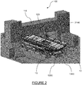
- FIG. 2 With reference to the figure 2 , there is shown a machining and welding system 100 of two elementary panels 1G, 1D.
- the machining and welding system 100 comprises a left support device 130G on which is positioned a left elementary panel 1G and a right support device 130D on which is positioned a right elementary panel 1D.
- an elementary panel 1G, 1D comprises a metal body 10 defining two opposite faces F1, F2 of which at least one face is covered with a coating 11 to be removed.
- the metal body 10 is made of aluminum alloy and has a thickness of between 1mm and 3mm.
- the coating 11 is made of pure aluminum and has a thickness of between 0.1mm and 0.3mm. Preferably, the coating 11 has a constant thickness.
- the metal body 10 has a thickness that can vary along the end of the panel 1G, 1D. As indicated above, the coating 11 must be accurately removed at the end of the panel 1G, 1D in order to guarantee an optimum quality weld. Because of its fineness, such an elementary panel 1G, 1D remains flexible and can be flattened by plastic deformation even if the latter has one or more curvatures.
- the invention will be presented for an elementary panel 1G, 1D comprising a coating to be removed on first face F1, but the invention also relates to an elementary panel 1G, 1D having no coating and for which it is desired to remove a thickness of one face of the metal body 10.
- the machining and welding system 100 comprises a displacement device 110 which is in this example in the form of a traveling gantry as shown in FIG. figure 2 .
- the displacement device 110 comprises a functional unit 120 on which different devices can be mounted, in particular a machining device 2 and a friction stir welding device 140.
- the functional unit 120 advantageously makes it possible to supply energy electrical, mechanical, hydraulic, pneumatic to connected devices.
- the displacement device 110 makes it possible, on the one hand, to move the machining device 2 to remove the coating at the end of each elementary panel 1G, 1D and, on the other hand, moving the friction stir welding device to join together the elementary panels 1G, 1D.
- the machining and welding system 100 two elementary panels 1G, 1D are welded quickly and conveniently.
- the support devices 130G, 130D are configured to firmly support the elementary panels 1G, 1D while keeping its machining end cantilevered so as to facilitate the passage of the machining device 2.
- the machining device 2 is positioned precisely relative to an elementary panel 1G, 1D which is fixedly fixed and the machining device 2 is moved along. one end of the elementary panel 1G, 1D in order to precisely machine it.
- a machining device 2 for machining an end of a left elementary panel 1G for friction stir welding.
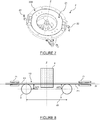
- the machining device 2 comprises a frame 20 and two guide members 3, mounted on the frame 20, and aligned in a horizontal reference direction Xr, the guide members 3 being configured to guide a first face F1 of a elementary panel 1G to precisely define its position.
- the machining device 2 further comprises a machining tool 4 mounted on the frame 20, the machining tool 4 being positioned between the two guide members 3 at a vertical position determined relative to the horizontal reference direction Xr to remove at least the coating 11 of the elementary panel 1G.
- the machining device 2 comprises two pressure members 5 configured to exert a pressure on the second face F2 of the elementary panel 1G so as to press the elementary panel 1G against the guide members 3.
- an elementary panel 1G is accurately and reliably positioned in the reference system of the machining device 2, which guarantees a very high precision machining guaranteeing optimum friction stir welding.
- the frame 20 of the machining device 2 can support the different bodies as will be presented later.
- the frame 20 comprises a lower part 20A on which are mounted the guide members 3 and an upper portion 20B on which is mounted the machining tool 4.
- the vertical distance between the lower portion 20A and the upper part 20B is adjustable, in particular by means of a vernier 72 or a micrometric stop, which makes it possible indirectly to adjust the vertical position of the machining tool 4 with respect to the horizontal reference direction Xr.
- a vernier 72 or a micrometric stop which makes it possible indirectly to adjust the vertical position of the machining tool 4 with respect to the horizontal reference direction Xr.
- Such a setting provides important accuracy.
- a positioning error of less than 0.05 mm can be obtained.
- the frame 20 comprises a movable base 21 configured to allow the rotation of the machining device 2 around a vertical axis Z.
- the movable base 21 can pivot relative to the upper portion 20B of the frame 20 about a vertical axis Z to change the orientation of the machining device 2 for machining both a left elementary panel 1G and a right elementary panel 1D as illustrated in FIG. figure 11 .
- the machining device 2 can rotate 180 °.
- the frame 20 comprises clamping jaws 22 for fixedly holding the movable base 21 relative to the upper part 20B in the two configurations of use, the clamping jaws 22 being loosened to change configuration.
- the machining device 2 comprises two guide members 3 configured to guide a first face F1 of the elementary panel 1G, in this example, the lower face F1.
- Each guide member 3 is each in the form of rollers to allow a rolling guide without the risk of marking / scratch the lower face F1 of the elementary panel 1G.
- the guide members 3 are mounted on the frame 20 and aligned in a horizontal reference direction Xr.
- the guide members 3 are rotatable so as to allow rolling guidance in the horizontal reference direction Xr.
- the guide members 3 form a frame specific to the frame 20.
- the reference horizontal direction is defined at the top of the guide members 3.
- the accuracy ⁇ Z3 between the center of a guide member 3 and the horizontal reference direction Xr is less than 0.05mm as illustrated in FIG. figure 8 .
- each guide member 3 is rigid so as to offer the lowest positioning tolerance possible.
- Each guide member 3 preferably has a polymer outer coating to limit the risk of marking the elementary panel 1G.
- the guide members 3 are spaced in the horizontal direction by a distance d3 which must be minimal to ensure a good holding while being large enough to reserve a working space for the machining tool 4 between the guide members 3 and avoid chip insertion.
- a distance d3 of between 50 mm and 150 mm is preferably adapted between 60 mm and 150 mm.
- Such a spacing is small compared to the radius of curvature of an elementary panel 1G, which makes it possible to consider that the elementary panel 1 is locally plane between the guide members 3 when it is pressed against the guide members 3.
- the machining device 2 moves according to the arrow AV, that is to say, from left to right on the figure 3 .
- the leftmost guide member 3 is designated “upstream guide member” while the rightmost guide member 3 is designated “downstream guide member”.
- upstream and downstream are defined relative to the horizontal direction of reference.
- the machining device 2 comprises a machining tool 4 mounted on the frame 20, in particular on its upper part 20B. As illustrated in figure 3 , the machining tool 4 is positioned between the two guide members 3 at a vertical position determined relative to the horizontal reference direction Xr.
- the vertical position of the machining tool 4 is easy to guarantee since it is defined by adjusting the vertical distance between the lower part 20A and the upper part 20B of the frame 20.
- the elementary panel 1 is guided in the frame of reference frame 20 for which the position of the machining tool 4 is perfectly defined. The reliability of the machining is thus greatly improved.
- the machining tool 4 comprises a machining surface for machining a lower face but may also comprise other machining surfaces for machining an upper face and / or a lateral face (flank) of the end of the elementary panel 1G.
- the machining tool 4 allows complete machining of the end of the elementary panel 1G.
- the machining tool 4 is rotated in the vertical direction at a rotation speed of 2000 to 4000 rpm.
- the lateral dimension of the guide members 3, defined orthogonally to the horizontal reference direction Xr, is greater than the lateral machining dimension. of the machining tool 4 so as to allow optimal guidance of the portion machined by the guide members 3.
- the width of the guide members 3 is 10 mm while the lateral dimension of machining is of the order of 3mm.
- the guide members 3 downstream of the machining tool 4 remain in contact with a non-machined portion of the order of 7 mm from the end of the elementary panel 1G in order to avoid any positioning defect.
- the machining tool 4 is aligned with the guide members 3 in the horizontal reference direction Xr.
- the machining tool 4 is offset laterally with respect to the horizontal reference direction Xr defined by the guide members 3 so that the guide members 3 are offset relative to the machined portion of the end of the elementary panel 1G during the displacement of the machining device 2.
- the machining device 2 comprises two pressure members 5 configured to exert pressure on the second face F2 of the elementary panel 1G so as to press the elementary panel 1G against the guide members 3.
- the pressure members 5 are aligned vertically with the guide members 3.
- the leftmost pressure member 5 is designated “upstream pressure member” while the rightmost pressure member 5 is is designated “downstream pressure member”.
- the end of the elementary panel 1G is sandwiched in two different horizontal positions, upstream and downstream of the machining tool 4, to ensure alignment of the end of the elementary panel 1G with the horizontal direction reference Xr with respect to which the machining tool 4 is positioned with high accuracy.
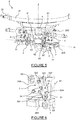
- the pressure members 5 are identical. For the sake of clarity and brevity, only the upstream pressure member 5 will be presented with reference to the Figures 5 and 6 .
- the upstream pressure member 5 comprises a roller 51 to allow guidance by turning without risk of marking / scratching the upper face F2 of the panel 1.
- the roller 51 is rigidly to offer the lowest positioning tolerance possible and preferably has a polymer outer coating to limit the risk of marking the elementary panel 1G.
- the upstream pressure member 5 further comprises a jack 52 to exert a constraint Downward vertical direction towards the upstream guide member 3.
- the cylinder 52 is connected to the roller 51 by a mechanism 53 for performing a curved displacement stroke. Nevertheless, it goes without saying that the cylinder 52 could be connected directly to the roller 51.
- the cylinder 52 of the upstream pressure member 5 extends horizontally and comprises, at its head, a pin 521 which is connected to the mechanism 53.
- the mechanism 53 is in the form of a longitudinal piece comprising a lower end 531 connected to the roller 51 by a pivot link 534 and an upper end 532 having a longitudinal slot 533 in which the pin 521 of the cylinder 52 can move in a pivot-sliding type connection.
- the longitudinal part forming the mechanism 53 is articulated to the upper part 20B of the frame 20 about an axis 54.
- the upstream pressure member 5 performs a tightening / loosening of the elementary panel 1G by performing a kinematics along an arc of circle, which allows to exert a gradual and controlled vertical pressure on the upper face F2 of the elementary panel 1G.
- the cylinder 52 expands to the right and the pin 521 enters the longitudinal slot 533 to drive the mechanism 53 in a clockwise rotation about the axis 54, which moves the roller 51 down against the elementary panel 1G according to an arcuate trajectory.
- the cylinder 52 contracts to the left and the pin 521 rises in the longitudinal slot 533 to drive it in rotation counterclockwise about the axis 54, which moves the roller 51 vertically upwards away from the elementary panel 1G in an arcuate path.
- each pressure member 5 comprises a pressure regulating element, preferably integrated with the jack 52, in order to calibrate the pressure applied to the elementary panel 1G during tightening.
- a pressure regulating element makes it possible to apply a substantially constant pressure even when the thickness of the elementary panel 1G is not constant.
- the roller 51 of the pressure member 5 is higher and the pressure is adapted to achieve optimal plating of the elementary panel 1G.
- the pressure regulating element is in the form of an electronic computing unit which is functionally connected to the jack 52.
- the pressure force exerted by a pressure member 5 is between 10N and 300N, in particular, less than 150N. It goes without saying that a pressure member could apply a higher pressure force, in particular up to 5000N.
- the machining device 2 comprises two global alignment members 71, in particular of the drain type. Similarly to previously, the machining device 2 comprises an upstream global alignment member 71 placed upstream of the upstream guide member 3 and a downstream global alignment member 71 placed downstream of the guide member. downstream 3. Global alignment members 71 make it possible to center the end of a unitary panel 1G prior to machining. Thus, the elementary panel 1G is progressively constrained to precisely control the position of the elementary panel 1G in the reference frame of the machining device 2.
- the global alignment members 71 are aligned in the horizontal reference direction Xr.
- Each global alignment member 71 has a convergent shape in the horizontal reference direction Xr in the direction of the machining tool 4.
- Such global alignment members 71 can globally guide the end of the elementary panel 1G before carrying out a constrained guidance in the immediate vicinity of the machining tool 4 with the guide members 3 and the pressure members 5.
- each global alignment member 71 comprises two oblique sheets but it is obvious one or more rollers could also be suitable.
- the machining device 2 also comprises two upper blowing members 61, in particular an upper blowing member 61 placed upstream of the machining tool 4 and an upper blowing member 61 placed downstream of the tool
- the upper blower members 61 allow blowing of air on the upper face F2 of the elementary panel 1G.
- the metal chips generated during machining are blown away from the pressure members 5 so as to avoid any local extra thickness that may affect the positioning of the elementary panel 1G or degradation of the reference system.
- each upper blower 61 is placed between the tool 4 and the pressure member 5 to prevent machining chips from coming into contact with the pressure member 5.
- the machining device 2 also comprises two lower blower members 62, in particular, a lower blower 62 placed upstream of the machining tool 4 and a lower blower 62 placed downstream of the tool 4.
- the lower blower members 62 can blow air on the lower face F1 of the elementary panel 1G.
- the metal chips generated during machining are blown away from the guide members 3 so as to avoid any local extra thickness that may affect the positioning of the elementary panel 1G or a degradation of the reference system.
- each lower blowing member 62 is placed between the machining tool 4 and the guide member 3 in order to prevent machining chips from coming into contact with the guide member 3.
- blowing members 61, 62 also make it possible to avoid marking the elementary panel 1G by the machining chips.
- the machining chips are collected by suction.
- the machining device 2 comprises a suction member 64, near the machining tool 4, to suck the chips.
- the upper blowing members 61 are inclined towards the machining tool 4 so as to facilitate central aspiration by the suction member 64.
- the horizontal reference direction Xr is protected during machining to avoid any deviation and guarantee precision machining.
- the machining device 2 also comprises two scanning members 63, in particular an upstream scanning member 63 placed upstream of the machining tool 4 and a downstream scanning member 63 placed downstream of the tool d 4.
- the scanning members 63 are aligned in the horizontal reference direction Xr.
- each scanning member 63 is configured to scan the lower face F1 and the upper face F2 of the elementary panel 1G.
- a scanning member 63 could scan only one face of the elementary panel 1G.
- the metal chips generated during machining are scanned so as not to come into contact with the pressure members 5 and the guiding members 3 so as to avoid any local extra thickness that may affect the orientation of the horizontal reference direction Xr .
- the horizontal reference direction Xr is protected during machining to avoid any deviation and ensure precision machining.
- the machining device 2 comprises one or more probes for measuring the thickness of the elementary panel 1G, 1D after machining its end to allow quality control to be carried out.
- a measurement probe of the laser type is preferred.
- the machining device 2 is mounted on a functional unit 120 of the machining and welding system 100 presented to the figure 2 .
- the displacement device 110 is connected to the movable base 21 of the frame 20 of the machining device 2 and makes it possible to move it, in particular along a substantially straight line so as to follow the end to be machined of the elementary panel 1G.
- FIG 11 there is shown a top view of a left elementary panel 1G and a right elementary panel 1D whose coating 11 is to be machined (declutching operation).
- the machining device 2 is moved along the left elementary panel 1G and the machining device 2 is rotated 180 ° before being moved along the right elementary panel 1D.
- the left elementary panel 1G moves relative to the machining device 2 during the movement of the functional unit 120 by the displacement device 110.
- the end of the left elementary panel 1G is centered by the global alignment members 71 then the guide members 3 and the pressure members 5 locally constrain the left elementary panel 1G so that its end is locally flat between the two stress zones. Due to its small thickness, this plastic deformation does not affect the left elementary panel 1G even if the latter comprises one or more curvatures.
- the end of the left elementary panel 1G is kept close to the area to be machined which extends cantilevered so as to allow space for the machining tool 4.
- the machining device 2 advantageously follows the end of the left elementary panel 1G to be positioned rigorously.
- the guide members 3 and the pressure members 5 define, two by two, two positions of reference along the horizontal reference direction Xr so as to perfectly control the position of the left elementary panel 1.
- the machining tool 4 is positioned between these two reference positions, its position is defined very precisely, this which guarantees high precision machining.
- the machining tool 4 is rotated and the machining device 2 is moved at a forward speed of between 150 to 800 mm / min. As the machining device 2 moves, the lining 11 of the left elementary panel 1 is accurately removed. The machining chips are blown, swept and / or aspirated so as not to disturb the machining or disrupt the maintenance of the left elementary panel 1G between the two reference positions, which guarantees a high accuracy.
- the lower face F1, the upper face F2 and / or the lateral face of the end of the left elementary panel 1G are machined so that the latter is able to be welded by friction mixing.
- the clamping jaws 22 of the mobile base 21 are loosened in order to change the orientation of the machining device 2 which can then machine the right elementary panel 1D in a similar way to the left elementary panel 1G.
- the machining device 2 is disconnected from the functional unit 120 and replaced by a friction stir welding device 140 as illustrated in FIG. figure 12 .
- the support devices 130G, 130D are adjusted to abut the ends of the elementary panels 1G, 1D as illustrated in FIG. figure 12 .
- the friction stir welding device 140 is activated and moved by the displacement device 110 at the interface between the elementary panels 1G, 1D so as to weld them together optimally.
- the elementary panels 1G, 1D are connected by a weld bead 12 as shown in FIG. figure 13 .
- the machining and welding system 100 could also comprise several functional units 120 so as to have concomitantly the machining device 2 and the friction stir welding device 140.
- the elementary panels 1G, 1D are conveniently machined with great precision.
- the integration in the same system of a machining device 2 and a welding device 140 allows to obtain a significant productivity while limiting the number of manipulation of the elementary panels.
- Removing repetitive steps of contact measurement saves significant time while increasing reliability and reducing costs.
Landscapes
- Engineering & Computer Science (AREA)
- Mechanical Engineering (AREA)
- Physics & Mathematics (AREA)
- Optics & Photonics (AREA)
- Pressure Welding/Diffusion-Bonding (AREA)
Priority Applications (1)
| Application Number | Priority Date | Filing Date | Title |
|---|---|---|---|
| DE19158761.7T DE19158761T1 (de) | 2018-02-23 | 2019-02-22 | Vorrichtung und verfahren zur bearbeitung einer extremität eines grundpaneels als vorbereitung auf seine bearbeitung durch reibrührschweissverfahren |
Applications Claiming Priority (1)
| Application Number | Priority Date | Filing Date | Title |
|---|---|---|---|
| FR1851602A FR3078280B1 (fr) | 2018-02-23 | 2018-02-23 | Dispositif et procede d'usinage d'une extremite d'un panneau elementaire en vue de son soudage par friction malaxage |
Publications (2)
| Publication Number | Publication Date |
|---|---|
| EP3530404A1 true EP3530404A1 (de) | 2019-08-28 |
| EP3530404B1 EP3530404B1 (de) | 2026-04-29 |
Family
ID=61913456
Family Applications (1)
| Application Number | Title | Priority Date | Filing Date |
|---|---|---|---|
| EP19158761.7A Active EP3530404B1 (de) | 2018-02-23 | 2019-02-22 | Vorrichtung und verfahren zur bearbeitung einer extremität eines grundpaneels als vorbereitung auf seine bearbeitung durch reibrührschweissverfahren |
Country Status (4)
| Country | Link |
|---|---|
| US (1) | US11752570B2 (de) |
| EP (1) | EP3530404B1 (de) |
| DE (1) | DE19158761T1 (de) |
| FR (1) | FR3078280B1 (de) |
Cited By (1)
| Publication number | Priority date | Publication date | Assignee | Title |
|---|---|---|---|---|
| CN120839521A (zh) * | 2025-09-19 | 2025-10-28 | 苏州晟成光伏设备有限公司 | 一种物料处理装置、处理方法及塑钢带接驳机 |
Families Citing this family (3)
| Publication number | Priority date | Publication date | Assignee | Title |
|---|---|---|---|---|
| CN114603246B (zh) * | 2022-04-08 | 2024-07-02 | 福建省南平铝业股份有限公司 | 一种镁铝异种合金焊接装置及方法 |
| EP4717384A1 (de) * | 2024-09-26 | 2026-04-01 | AIRBUS Operations GmbH | Verfahren, steuerprogramm, computerlesbarer datenträger, steuereinheit und fräsvorrichtung zum fräsen einer deckschicht von blechen |
| CN119457400B (zh) * | 2025-01-14 | 2025-05-23 | 南昌航空大学 | 一种用于搅拌摩擦点焊的快压夹具及其使用方法 |
Citations (4)
| Publication number | Priority date | Publication date | Assignee | Title |
|---|---|---|---|---|
| GB1413106A (en) * | 1971-10-12 | 1975-11-05 | Hurn Brothers Eng Ltd | Apparatus for working elongate components at successive longitudinal locations |
| JPH1052773A (ja) * | 1996-08-06 | 1998-02-24 | Hitachi Ltd | 鉄道車両用構体の製作方法及び製作装置 |
| US5971247A (en) * | 1998-03-09 | 1999-10-26 | Lockheed Martin Corporation | Friction stir welding with roller stops for controlling weld depth |
| JP2001047262A (ja) * | 1999-05-28 | 2001-02-20 | Hitachi Ltd | 構造体の製作方法および装置 |
Family Cites Families (7)
| Publication number | Priority date | Publication date | Assignee | Title |
|---|---|---|---|---|
| SE450695B (sv) * | 1983-07-01 | 1987-07-20 | Sture Hall | Apparat for fogberedning av platar avsedda att svetsas |
| JP3357788B2 (ja) * | 1996-06-25 | 2002-12-16 | 日本原子力研究所 | 両面加工装置 |
| JP2006142434A (ja) * | 2004-11-19 | 2006-06-08 | Fuji Heavy Ind Ltd | 切削装置 |
| JP5548530B2 (ja) * | 2010-06-15 | 2014-07-16 | 東芝機械株式会社 | 工具、および工作機械 |
| KR101436084B1 (ko) * | 2012-08-20 | 2014-08-29 | 주식회사 세한코리아 | 챔퍼밀 |
| JP6099291B1 (ja) * | 2015-12-28 | 2017-03-22 | ヤマザキマザック株式会社 | 摩擦攪拌接合用工具及び工作機械 |
| US10016838B2 (en) * | 2016-03-18 | 2018-07-10 | Toshiba Kikai Kabushiki Kaisha | Friction stir welding tool |
-
2018
- 2018-02-23 FR FR1851602A patent/FR3078280B1/fr active Active
-
2019
- 2019-02-22 EP EP19158761.7A patent/EP3530404B1/de active Active
- 2019-02-22 US US16/283,436 patent/US11752570B2/en active Active
- 2019-02-22 DE DE19158761.7T patent/DE19158761T1/de active Pending
Patent Citations (4)
| Publication number | Priority date | Publication date | Assignee | Title |
|---|---|---|---|---|
| GB1413106A (en) * | 1971-10-12 | 1975-11-05 | Hurn Brothers Eng Ltd | Apparatus for working elongate components at successive longitudinal locations |
| JPH1052773A (ja) * | 1996-08-06 | 1998-02-24 | Hitachi Ltd | 鉄道車両用構体の製作方法及び製作装置 |
| US5971247A (en) * | 1998-03-09 | 1999-10-26 | Lockheed Martin Corporation | Friction stir welding with roller stops for controlling weld depth |
| JP2001047262A (ja) * | 1999-05-28 | 2001-02-20 | Hitachi Ltd | 構造体の製作方法および装置 |
Cited By (2)
| Publication number | Priority date | Publication date | Assignee | Title |
|---|---|---|---|---|
| CN120839521A (zh) * | 2025-09-19 | 2025-10-28 | 苏州晟成光伏设备有限公司 | 一种物料处理装置、处理方法及塑钢带接驳机 |
| CN120839521B (zh) * | 2025-09-19 | 2026-02-24 | 苏州晟成光伏设备有限公司 | 一种物料处理装置、处理方法及塑钢带接驳机 |
Also Published As
| Publication number | Publication date |
|---|---|
| FR3078280B1 (fr) | 2020-03-20 |
| EP3530404B1 (de) | 2026-04-29 |
| DE19158761T1 (de) | 2020-04-16 |
| US20190262933A1 (en) | 2019-08-29 |
| US11752570B2 (en) | 2023-09-12 |
| FR3078280A1 (fr) | 2019-08-30 |
Similar Documents
| Publication | Publication Date | Title |
|---|---|---|
| EP3530404B1 (de) | Vorrichtung und verfahren zur bearbeitung einer extremität eines grundpaneels als vorbereitung auf seine bearbeitung durch reibrührschweissverfahren | |
| EP2964436B2 (de) | Regulierbare anordnung zur umwandlung einer ebenen halterung, kassette, einheit und damit ausgestattete maschine | |
| EP2064023B1 (de) | Vorrichtung und verfahren zur schweissverbindung von bahnenmetallstreifen | |
| FR3135002A1 (fr) | Méthode d'assemblage d'un panneau avec raidisseur et poste d'assemblage associé | |
| CA2954462A1 (fr) | Procede de rompage d'une feuille de verre | |
| WO2012095589A2 (fr) | Procédé de positionnement mutuel de tubes | |
| FR2840844A1 (fr) | Disque couper a plongee rotative avec contre-partie rainuree de style a griffe | |
| EP2424704B1 (de) | Mechanisches system zur automatischen führung von ein oder mehr lötlampen eines schweissgeräts mit drei drehachsen für die lötlampe oder lötlampen | |
| EP0640435A1 (de) | Schleifmaschine | |
| FR2801820A1 (fr) | Appareil et procede d'assemblage de bandes | |
| EP1591190B1 (de) | Verfahren zum Verschweissen zweier Metallbleche | |
| EP1127654B1 (de) | Verfahren und Vorrichtung zum Stumpfschweissen von metallischen Blechen | |
| US20130153549A1 (en) | Apparatus and method for manufacturing a swing-ring plate | |
| EP3271109B1 (de) | Verfahren zur reparatur der zähne eines zahnkranzes | |
| EP0650796A1 (de) | Verfahren und Vorrichtung zum Herstellen der Rechtwinkligkeit und zum Verschweissen metallischer Bänder | |
| FR2588792A1 (fr) | Procede et dispositif d'usinage ou de controle sur site pour pieces rotatives | |
| WO2000029152A1 (fr) | Dispositif de perçage de trous fil freins | |
| FR2662105A1 (fr) | Procede et dispositif d'equerrage pour le cisaillage de toles. | |
| EP2134503B1 (de) | Verfahren und vorrichtung zur bestimmung der geometrie des dachs und der karosserie eines kraftfahrzeugs | |
| FR2884447A1 (fr) | Installation et procede de fabrication d'un fut metallique soude | |
| FR2529107A1 (fr) | Procede et installation de fabrication de tube d'acier soude en helice | |
| EP1086768B1 (de) | Streifenschere mit kompensierter Durchbiegung | |
| EP3038963B1 (de) | Verfahren zum verschweissen zweier thermoschmelzbarer artikel in form von streifen oder schichten und spleissmodul zur durchführung dieses verfahrens | |
| FR2597404A1 (fr) | Machine pour le traitement d'une seule face d'un article, notamment de carton ondule | |
| FR3037267A1 (fr) | Procede et outil de soudure par friction malaxage |
Legal Events
| Date | Code | Title | Description |
|---|---|---|---|
| PUAI | Public reference made under article 153(3) epc to a published international application that has entered the european phase |
Free format text: ORIGINAL CODE: 0009012 |
|
| STAA | Information on the status of an ep patent application or granted ep patent |
Free format text: STATUS: THE APPLICATION HAS BEEN PUBLISHED |
|
| AK | Designated contracting states |
Kind code of ref document: A1 Designated state(s): AL AT BE BG CH CY CZ DE DK EE ES FI FR GB GR HR HU IE IS IT LI LT LU LV MC MK MT NL NO PL PT RO RS SE SI SK SM TR |
|
| AX | Request for extension of the european patent |
Extension state: BA ME |
|
| STAA | Information on the status of an ep patent application or granted ep patent |
Free format text: STATUS: REQUEST FOR EXAMINATION WAS MADE |
|
| 17P | Request for examination filed |
Effective date: 20200225 |
|
| RBV | Designated contracting states (corrected) |
Designated state(s): AL AT BE BG CH CY CZ DE DK EE ES FI FR GB GR HR HU IE IS IT LI LT LU LV MC MK MT NL NO PL PT RO RS SE SI SK SM TR |
|
| REG | Reference to a national code |
Ref country code: DE Ref legal event code: R210 |
|
| RAP3 | Party data changed (applicant data changed or rights of an application transferred) |
Owner name: AIRBUS ATLANTIC |
|
| STAA | Information on the status of an ep patent application or granted ep patent |
Free format text: STATUS: EXAMINATION IS IN PROGRESS |
|
| 17Q | First examination report despatched |
Effective date: 20220707 |
|
| GRAP | Despatch of communication of intention to grant a patent |
Free format text: ORIGINAL CODE: EPIDOSNIGR1 |
|
| STAA | Information on the status of an ep patent application or granted ep patent |
Free format text: STATUS: GRANT OF PATENT IS INTENDED |
|
| INTG | Intention to grant announced |
Effective date: 20251128 |
|
| GRAJ | Information related to disapproval of communication of intention to grant by the applicant or resumption of examination proceedings by the epo deleted |
Free format text: ORIGINAL CODE: EPIDOSDIGR1 |
|
| STAA | Information on the status of an ep patent application or granted ep patent |
Free format text: STATUS: EXAMINATION IS IN PROGRESS |
|
| GRAP | Despatch of communication of intention to grant a patent |
Free format text: ORIGINAL CODE: EPIDOSNIGR1 |
|
| STAA | Information on the status of an ep patent application or granted ep patent |
Free format text: STATUS: GRANT OF PATENT IS INTENDED |
|
| GRAS | Grant fee paid |
Free format text: ORIGINAL CODE: EPIDOSNIGR3 |
|
| GRAA | (expected) grant |
Free format text: ORIGINAL CODE: 0009210 |
|
| STAA | Information on the status of an ep patent application or granted ep patent |
Free format text: STATUS: THE PATENT HAS BEEN GRANTED |
|
| INTC | Intention to grant announced (deleted) | ||
| REG | Reference to a national code |
Ref country code: DE Ref legal event code: R081 Ref document number: 602019084119 Country of ref document: DE Owner name: AIRBUS ATLANTIC, FR Free format text: FORMER OWNER: STELIA AEROSPACE, ROCHEFORT, FR Ref country code: DE Ref legal event code: R082 Ref document number: 602019084119 Country of ref document: DE |
|
| INTG | Intention to grant announced |
Effective date: 20260312 |
|
| AK | Designated contracting states |
Kind code of ref document: B1 Designated state(s): AL AT BE BG CH CY CZ DE DK EE ES FI FR GB GR HR HU IE IS IT LI LT LU LV MC MK MT NL NO PL PT RO RS SE SI SK SM TR |
|
| REG | Reference to a national code |
Ref country code: CH Ref legal event code: F10 Free format text: ST27 STATUS EVENT CODE: U-0-0-F10-F00 (AS PROVIDED BY THE NATIONAL OFFICE) Effective date: 20260429 Ref country code: GB Ref legal event code: FG4D Free format text: NOT ENGLISH |
|
| REG | Reference to a national code |
Ref country code: IE Ref legal event code: FG4D Free format text: LANGUAGE OF EP DOCUMENT: FRENCH |
|
| REG | Reference to a national code |
Ref country code: DE Ref legal event code: R096 Ref document number: 602019084119 Country of ref document: DE |
|
| P01 | Opt-out of the competence of the unified patent court (upc) registered |
Free format text: CASE NUMBER: UPC_APP_0017334_3530404/2026 Effective date: 20260603 |