EP3530562A1 - Heckanschlagerkennungssystem - Google Patents
Heckanschlagerkennungssystem Download PDFInfo
- Publication number
- EP3530562A1 EP3530562A1 EP19158293.1A EP19158293A EP3530562A1 EP 3530562 A1 EP3530562 A1 EP 3530562A1 EP 19158293 A EP19158293 A EP 19158293A EP 3530562 A1 EP3530562 A1 EP 3530562A1
- Authority
- EP
- European Patent Office
- Prior art keywords
- tailstrike
- aircraft
- probability
- processor
- occurring
- Prior art date
- Legal status (The legal status is an assumption and is not a legal conclusion. Google has not performed a legal analysis and makes no representation as to the accuracy of the status listed.)
- Granted
Links
Images










Classifications
-
- G—PHYSICS
- G05—CONTROLLING; REGULATING
- G05D—SYSTEMS FOR CONTROLLING OR REGULATING NON-ELECTRIC VARIABLES
- G05D1/00—Control of position, course, altitude or attitude of land, water, air or space vehicles, e.g. using automatic pilots
- G05D1/08—Control of attitude, i.e. control of roll, pitch, or yaw
- G05D1/0808—Control of attitude, i.e. control of roll, pitch, or yaw specially adapted for aircraft
-
- B—PERFORMING OPERATIONS; TRANSPORTING
- B64—AIRCRAFT; AVIATION; COSMONAUTICS
- B64C—AEROPLANES; HELICOPTERS
- B64C13/00—Control systems or transmitting systems for actuating flying-control surfaces, lift-increasing flaps, air brakes, or spoilers
- B64C13/02—Initiating means
- B64C13/04—Initiating means actuated personally
- B64C13/10—Initiating means actuated personally comprising warning devices
-
- B—PERFORMING OPERATIONS; TRANSPORTING
- B64—AIRCRAFT; AVIATION; COSMONAUTICS
- B64C—AEROPLANES; HELICOPTERS
- B64C13/00—Control systems or transmitting systems for actuating flying-control surfaces, lift-increasing flaps, air brakes, or spoilers
- B64C13/02—Initiating means
- B64C13/04—Initiating means actuated personally
-
- B—PERFORMING OPERATIONS; TRANSPORTING
- B64—AIRCRAFT; AVIATION; COSMONAUTICS
- B64D—EQUIPMENT FOR FITTING IN OR TO AIRCRAFT; FLIGHT SUITS; PARACHUTES; ARRANGEMENT OR MOUNTING OF POWER PLANTS OR PROPULSION TRANSMISSIONS IN AIRCRAFT
- B64D43/00—Arrangements or adaptations of instruments
-
- B—PERFORMING OPERATIONS; TRANSPORTING
- B64—AIRCRAFT; AVIATION; COSMONAUTICS
- B64D—EQUIPMENT FOR FITTING IN OR TO AIRCRAFT; FLIGHT SUITS; PARACHUTES; ARRANGEMENT OR MOUNTING OF POWER PLANTS OR PROPULSION TRANSMISSIONS IN AIRCRAFT
- B64D45/00—Aircraft indicators or protectors not otherwise provided for
-
- B—PERFORMING OPERATIONS; TRANSPORTING
- B64—AIRCRAFT; AVIATION; COSMONAUTICS
- B64D—EQUIPMENT FOR FITTING IN OR TO AIRCRAFT; FLIGHT SUITS; PARACHUTES; ARRANGEMENT OR MOUNTING OF POWER PLANTS OR PROPULSION TRANSMISSIONS IN AIRCRAFT
- B64D45/00—Aircraft indicators or protectors not otherwise provided for
- B64D45/04—Landing aids; Safety measures to prevent collision with earth's surface
-
- B—PERFORMING OPERATIONS; TRANSPORTING
- B64—AIRCRAFT; AVIATION; COSMONAUTICS
- B64D—EQUIPMENT FOR FITTING IN OR TO AIRCRAFT; FLIGHT SUITS; PARACHUTES; ARRANGEMENT OR MOUNTING OF POWER PLANTS OR PROPULSION TRANSMISSIONS IN AIRCRAFT
- B64D47/00—Equipment not otherwise provided for
- B64D47/02—Arrangements or adaptations of signal or lighting devices
-
- B—PERFORMING OPERATIONS; TRANSPORTING
- B64—AIRCRAFT; AVIATION; COSMONAUTICS
- B64D—EQUIPMENT FOR FITTING IN OR TO AIRCRAFT; FLIGHT SUITS; PARACHUTES; ARRANGEMENT OR MOUNTING OF POWER PLANTS OR PROPULSION TRANSMISSIONS IN AIRCRAFT
- B64D45/00—Aircraft indicators or protectors not otherwise provided for
- B64D2045/0085—Devices for aircraft health monitoring, e.g. monitoring flutter or vibration
Definitions
- the present disclosure relates to tailstrikes.
- it relates to a tailstrike awareness system (TSAS) to reduce the probability of the occurrence of an aircraft's tailstrike.
- TSAS tailstrike awareness system
- a tailstrike is an event in which the tail of the fuselage of a fixed-wing aircraft strikes the runway.
- Tailstrikes can occur during takeoff of the aircraft when the pilot pulls up on the pitch control inceptor too rapidly, thereby causing the tail of the aircraft fuselage to touch the runway.
- Tailstrikes can also occur during landing of the aircraft when the pilot raises the nose of the aircraft too aggressively, which is often the result of an attempt to land the aircraft closer to the threshold of the runway. Tailstrike incidents are rarely dangerous themselves. However, after a tailstrike incident occurs, the aircraft must be thoroughly inspected, and repairs may be difficult and expensive if the pressure hull is compromised.
- aircraft are either configured with a longer or semi-levered main landing gear; or with tilting main landing gear bogies, small tailwheels, or tailskids.
- the former solutions require a new or modified landing gear design, or a redesigning of the wheel well.
- the latter solutions require adding structural shock absorbing to the rear of the aircraft fuselage to compensate for the aircraft landing ground contact energy.
- a method for reducing a probability of an occurrence of a tailstrike for an aircraft comprising determining, by at least one processor of the aircraft, whether a tailstrike has a first probability of occurring by using tailstrike related data.
- the method further comprises producing, by an actuator of the aircraft, a tactile warning to a pilot of the aircraft, when at least one processor determines that the tailstrike has the first probability of occurring.
- the determining of whether the tailstrike has the first probability of occurring comprises: determining, by at least one processor, whether an aircraft pitch attitude is greater than a first probability threshold by using the tailstrike related data; and determining, by at least one processor, that the tailstrike has the first probability of occurring, when the aircraft pitch attitude is greater than the first probability threshold.
- the method further comprises determining, by at least one processor, whether a tailstrike has a second probability of occurring by using the tailstrike related data. Also, the method comprises displaying, on a display, a visual warning, and/or sounding, by a speaker, an audible warning, when at least one processor determines that the tailstrike has the second probability of occurring.
- the determining of whether the tailstrike has the second probability of occurring comprises: determining, by at least one processor, whether an aircraft pitch attitude is greater than a second probability threshold by using the tailstrike related data; and determining, by at least one processor, that the tailstrike has the second probability of occurring, when the aircraft pitch attitude is greater than the second probability threshold.
- the tailstrike related data comprises aircraft systems set for takeoff or landing configuration, speedbrake system status, engine thrust control status, high lift system status, landing gear status, aircraft altitude, pilot pitch input force, airport data of aircraft dynamics, aircraft pitch attitude, aircraft sink rate, and/or aircraft angle of attack.
- the tactile warning is a force and/or a vibration applied to a pitch control inceptor in a cockpit of the aircraft.
- the actuator is connected to the pitch control inceptor via a linkage mechanism.
- the linkage mechanism is connected to a leaf spring, helical spring, or an elastic object. The actuator changes the mechanical advantage between the leaf spring and the pitch control inceptor.
- the producing of the tactile warning comprises moving, by changing a stroke of the actuator and deforming the leaf spring, the linkage mechanism to provide a force on the pitch control inceptor, which is felt by the pilot of the aircraft.
- the aircraft comprises a fly-by-wire flight control system or does not comprise a fly-by-wire flight control system.
- characteristics of the tactile warning comprise: a magnitude of pilot input force is a function of actuator stroke, the pilot input force is smoothly increased when the tailstrike has the first probability of occurring, the pilot input force is smoothly ramped out when the tailstrike no longer has the first probability of occurring, and/or there are at least two distinct force gradients for the actuator stroke.
- the method further comprises disengaging the linkage mechanism from the pitch control inceptor, thereby allowing for unimpeded movement of the pitch control inceptor.
- the method further comprises determining, by at least one processor, whether the actuator can be fully extended. In some examples, the method further comprises activating a warning light associated with a health status of the actuator, by at least one processor, when at least one processor determines that the actuator cannot be fully extended.
- a system for reducing a probability of an occurrence of a tailstrike for an aircraft comprises at least one processor, of the aircraft, to determine whether a tailstrike has a first probability of occurring by using tailstrike related data.
- the system further comprises an actuator, of the aircraft, to produce a tactile warning to a pilot of the aircraft, if at least one processor determines that the tailstrike has the first probability of occurring.
- At least one processor is further to determine whether an aircraft pitch attitude is greater than a first probability threshold by using the tailstrike related data; and to determine that the tailstrike has the first probability of occurring, if the aircraft pitch attitude is greater than the first probability threshold.
- At least one processor is further to determine whether a tailstrike has a second probability of occurring by using the tailstrike related data.
- the system further comprises a display to display a visual warning and/or a speaker to sound an audible warning, if at least one processor determines that the tailstrike has the second probability of occurring.
- At least one processor is further to determine whether an aircraft pitch attitude is greater than a second probability threshold by using the tailstrike related data; and to determine that the tailstrike has the second probability of occurring, if the aircraft pitch attitude is greater than the second probability threshold.
- a stroke of the actuator is changed and the leaf spring is deformed to move the linkage mechanism to provide a force on the pitch control inceptor, which is to be felt by the pilot of the aircraft.
- the methods and apparatus disclosed herein provide an operative system for reducing the probability of the occurrence of an aircraft's tailstrike.
- the system of the present disclosure provides a tactile warning to an aircraft pilot of an imminent tailstrike occurring.
- a tailstrike is an inadvertent contact of the tailskid or aft body of an aircraft with a runway during takeoff or landing of a fixed-wing or rotary wing aircraft.
- Tailstrikes can occur during takeoff of the aircraft when the pilot pulls up on the control inceptor too rapidly, thereby causing the tail of the aircraft fuselage to touch the runway.
- tailstrikes can occur during landing of the aircraft when the pilot raises the nose of the aircraft too aggressively, which is often the result of an attempt to land the aircraft closer to the threshold of the runway.
- Tailstrike incidents are rarely dangerous themselves. However, after a tailstrike incident occurs, the aircraft must be thoroughly inspected, and repairs may be difficult and expensive if the pressure hull is compromised.
- aircraft are either configured with a longer or semi-levered main landing gear; or with tilting main landing gear bogies, small tailwheels, or tailskids.
- the former solutions require a new or modified landing gear design, or a redesigning of the wheel well.
- the latter solutions require adding structural shock absorbing to the rear of the aircraft fuselage to compensate for the aircraft landing ground contact energy.
- the system of the present disclosure aims to reduce tailstrike incidents by quickly providing feedback in the form of a tactile warning to the pilot of an imminent tailstrike so that the pilot can focus on the appropriate control input to the aircraft to avoid the tailstrike.
- the system receives tailstrike related data, such as aircraft dynamics and external conditions (e.g., aircraft takeoff or landing configuration, aircraft angle of attack, etc.), to determine whether a tailstrike has a first probability of occurring and, if so, the system provides a resistant force (and/or vibration) on the pitch control inceptor, which is felt by the pilot.
- Examples of the present disclosure may be described herein in terms of functional and/or logical components and various processing steps. It should be appreciated that such components may be realized by any number of hardware, software, and/or firmware components configured to perform the specified functions.
- An example of the present disclosure may employ various integrated circuit components (e.g., memory elements, digital signal processing elements, logic elements, look-up tables, or the like), which may carry out a variety of functions under the control of one or more processors, microprocessors, or other control devices.
- integrated circuit components e.g., memory elements, digital signal processing elements, logic elements, look-up tables, or the like
- FIG. 1 is a flow chart showing the disclosed method 100 for reducing the probability of the occurrence of an aircraft's tailstrike, in accordance with at least one example of the present disclosure.
- design criteria e.g., the aircraft dimensions and features for the specific model of aircraft
- threshold 1 i.e. a first probability threshold
- Threshold 1 indicates a higher probability of a tailstrike occurring than threshold 2.
- threshold 1 and threshold 2 may be determined during the design phase of the aircraft, when the aircraft configuration is still in the define phase, and/or by a software update for at least one processor on the aircraft during flight test phase of the aircraft.
- At least one processor on the aircraft analyzes tailstrike related data (e.g., speedbrake system status, engine thrust control status, high lift system status, landing gear status, aircraft altitude, pilot pitch input force, aircraft pitch attitude, aircraft sink rate, and aircraft angle of attack) to determine whether a tailstrike occurrence is imminent. If the processor(s) determines that a tailstrike occurrence is imminent, then a flight deck warning and/or a tactile warning is activated to warn the pilot.
- tailstrike related data e.g., speedbrake system status, engine thrust control status, high lift system status, landing gear status, aircraft altitude, pilot pitch input force, aircraft pitch attitude, aircraft sink rate, and aircraft angle of attack
- At the start 105 of the method 100 during operation of the aircraft, at least one processor analyzes the aircraft systems configuration (e.g., speedbrake system status, engine thrust control status, high lift system status, landing gear status, and pilot communication data with the airport) to determine whether the aircraft systems are set for a takeoff configuration or a landing configuration 140.
- the aircraft systems configuration e.g., speedbrake system status, engine thrust control status, high lift system status, landing gear status, and pilot communication data with the airport
- the processor(s) determines that the actuator stroke is not equal to zero, then the processor(s) commands the actuator (refer to 250 of FIG. 3C ) to attempt to fully extend its ball nut (refer to 260 of FIG. 3C ) to its reference position such that the actuator stroke is equal to zero. If the actuator is able to fully extend such that the actuator stroke is equal to zero, then the processor(s) determines that the actuator health status is fine, and the method 100 proceeds back to the start 105.
- the processor(s) determines that the actuator health status is not fine, and the a warning light (refer to 249 of FIG. 3A ) indicating that the actuator is unable to fully extend is activated (i.e. illuminated) 146.
- a warning light (refer to 249 of FIG. 3A ) indicating that the actuator is unable to fully extend is activated (i.e. illuminated) 146.
- various different types of warnings may be utilized for the warning light including, but not limited to, at least one light and/or textual warning displayed on a display on the flight deck of the cockpit of the aircraft.
- the pilot is notified that since the actuator is unable to fully extend, the pilot will need to use extra force on the pitch control inceptor (refer to 220a in FIG. 2 ) during normal flight control mode. Then, the method 100 proceeds back to the start 105.
- the processor(s) determines that the aircraft systems are set for a takeoff configuration or a landing configuration, then the processor(s) analyzes the aircraft dynamics relative to the runway (e.g., aircraft altitude, aircraft location, aircraft sink rate, and aircraft angle of attack) to determine whether the aircraft is close to the runway (i.e. low to the ground) by a predetermined distance 150. If the processor(s) determines that the aircraft is not close to the runway, then the method 100 repeats to the start 105.
- the runway e.g., aircraft altitude, aircraft location, aircraft sink rate, and aircraft angle of attack
- the processor(s) determines the aircraft pitch attitude by, for example, analyzing some or all of the tailstrike related data 160. Then, the processor(s) determines whether the aircraft pitch attitude is greater than threshold 2 (i.e. a second probability threshold). If the processor(s) determines that the aircraft pitch attitude is not greater than threshold 2, then the method repeats to the start 105.
- threshold 2 i.e. a second probability threshold
- a flight deck warning is activated 180.
- Various different types of warnings may be utilized for the flight deck warning including, but not limited to, visual warnings (e.g., at least one light and/or textual warning displayed on a display on the flight deck of the cockpit of the aircraft) and audible warnings (e.g., at least one sound and/or word sounded by a speaker in the cockpit).
- the processor(s) determines whether the aircraft pitch attitude is greater than threshold 1 (i.e. a first probability threshold) 190. If the processor(s) determines that the aircraft pitch attitude is not greater than threshold 1, then the method 100 repeats to the start 105.
- threshold 1 i.e. a first probability threshold
- a tailstrike awareness system (TSAS) actuator is activated 195.
- the TSAS actuator provides a tactile warning in the form of a resistant force (and/or vibration) on the pitch control inceptor, which is felt by the pilot. Then, the method 100 repeats to the start 105.
- a tactile warning in the form of a resistant force (and/or vibration) on the pitch control inceptor may be implemented to warn the pilot of an imminent tailstrike.
- the description below of the following figures discloses exemplary examples for providing a tactile warning to the pilot of an imminent tailstrike occurrence.
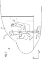
- FIG. 2 is a diagram illustrating the disclosed system 200 for reducing the probability of the occurrence of an aircraft's tailstrike, in accordance with at least one example of the present disclosure.
- the system 200 of the aircraft 210 is extracted from the aircraft 210 to show its details.
- the system 200 is shown to comprise two pitch control inceptors 220a, 220b (i.e. the captain pitch control inceptor 220a and the first officer pitch control inceptor 220b), which are both located inside the cockpit 215 of the aircraft 210.
- the two pitch control inceptors 220a, 220b are connected to each other via a crossbar 390.
- the two pitch control inceptors 220a and 220b are not connected to each other via a crossbar 390.
- a separate tailstrike awareness system (TSAS) will be employed for each pitch control inceptor 220a, 220b (i.e. each pitch control inceptor 220a, 220b will have its own dedicated actuator 250 and linkage mechanism 355).
- TSAS tailstrike awareness system
- Each pitch control inceptor 220a, 220b is connected to a respective cable 230a, 230b.
- the cables 230a, 230b are both connected to a feel and centering unit 235 and elevator actuators 236, which are located within the tail 217 of the fuselage of the aircraft 210.
- the feel and centering unit 235 provides an artificial feel force for the pilot during normal flight control mode.
- the elevator actuators 236 control the movement of the left elevator 240a and the right elevator 240b of the aircraft 210 according to the movement of the pitch control inceptors 220a, 220b.
- an actuator 250 is shown to be connected to a linkage mechanism 355.
- the linkage mechanism is connected to the crossbar 390 via a pitch inceptor 310.
- a flight computer e.g., a processor(s)
- TSAS tailstrike awareness system
- the flight computer 245 processes and commands aspects of flight of the aircraft 210 including, but not limited to, the aircraft's dynamics and system settings.
- the flight computer 245 communicates with the actuator 250 via wire 225 and control relay 246 (refer to FIG. 3A ).
- the flight computer 245 sends commands to the actuator 250 via wire 225 to cause movement to the linkage mechanism 355. Movement of the linkage mechanism 355 demands a pilot pitch inceptor force, which the pilot has to apply to the pitch control inceptor 220a in order to move the pitch inceptor away from its neutral position (i.e. away from zero (0) degrees, refer to FIG. 7 ).
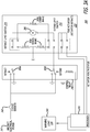
- FIG. 3A is a diagram illustrating the electrical system elements employed by the disclosed system for reducing the probability of the occurrence of an aircraft's tailstrike when the actuator 250 is extended, in accordance with at least one example of the present disclosure.
- a processor(s) e.g., within the flight computer 245 determines that the aircraft pitch attitude is not greater than threshold 1 (i.e. indicating a normal flight control mode where a tailstrike occurrence is not imminent)
- the processor(s) 245 confirms that the ball nut 260 (refer to FIG. 3C ) of the actuator 250 is fully extended.
- the processor 245 determines that the ball nut 260 is not fully extended, then the processor 245 sends at least one command (i.e. a TSAS actuator command) to the control relay 246.
- a TSAS actuator command i.e. a TSAS actuator command
- the limit switch 304a is open (as shown in FIG. 3A ) and the limit switch 304b is closed (as shown in FIG. 3A ) and, as such, the aircraft electrical power 247 is connected to the motor 280 (via a circuit breaker 248), which causes the actuator 250 to fully extend its ball nut 260 such that the actuator stroke is equal to zero (refer to FIG. 3C ). Since the actuator 250 is able to be fully extended, the warning light 249 is not activated ("OFF").
- the processor(s) 245 determines that the aircraft pitch attitude is greater than threshold 1 (i.e. indicating that a tailstrike occurrence is imminent)
- the processor(s) 245 sends at least one command (i.e. a TSAS actuator command) to the actuator 250 via control relay 246 (refer to FIG. 3A ) to switch limit switch 304a closed (not shown in FIG. 3A ) and switch limit switch 304b open (not shown in FIG. 3A ).
- aircraft electrical power 247 is connected to the motor 280 (via a circuit breaker 248), which causes the actuator 250 to retract its ball nut 260 (refer to FIG. 3C ).
- FIG. 3B is a diagram illustrating the electrical system elements employed by the disclosed system for reducing the probability of the occurrence of an aircraft's tailstrike when the system is experiencing a short and the actuator 250 is retracted, in accordance with at least one example of the present disclosure.
- the short voltage 251 switches the extend limit switches 255 open (as shown in FIG. 3B ) and switches retract limit switches 270 closed (as shown in FIG. 3B ).
- the aircraft electrical power 247 is connected to the motor 280 (via a circuit breaker 248), which causes the actuator 250 to retract its ball nut 260 (refer to FIG. 3C ).
- a warning light 249 is activated ("ON") to notify the pilot is that the actuator 250 is unable to fully extend and, as such, the pilot will need to use extra force to pull up on the pitch control inceptor (refer to 220a in FIG. 2 ) during normal flight control mode.
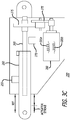
- FIG. 3C is a diagram showing an exemplary actuator 250 that may be employed by the disclosed system for reducing the probability of the occurrence of an aircraft's tailstrike, in accordance with at least one example of the present disclosure.
- the actuator 250 is shown to include a motor 280, which comprises a series brake 305a and a shunt brake 305b.
- the motor 280 is connected to reduction gearing 275, which is used to rotate a ball screw 265 (or other type of screw, which may be implemented for other examples).
- the rotation of the ball screw 265 (or other type of screw) produces a linear travel of the ball nut 260 (or other type of nut, which may be implemented for other examples) to extend or to retract.
- actuator stroke which will be discussed in the description of FIG. 8 , is in reference to the distance the ball nut 260 travels within the actuator 250 from a reference position (REF) (e.g., the fully extended position of the ball nut 260).
- REF reference position
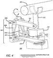
- FIG. 4 is a diagram showing an exemplary tailstrike awareness system (TSAS) mechanism 400 that may be employed by the disclosed system for reducing the probability of the occurrence of an aircraft's tailstrike, in accordance with at least one example of the present disclosure.
- the TSAS mechanism 400 is shown to comprise a pitch inceptor 310, where one end of the pitch inceptor 310 is connected to the crossbar 390.
- the end of the pitch inceptor 310 may be connected to the crossbar 390 by various different means including, but not limited to, a crank (e.g., refer to FIG. 2 ).
- the opposite end of the pitch inceptor 310 is connected to a linkage mechanism 355 via a push rod 320 of the linkage mechanism 355.
- the TSAS mechanism 400 comprises all of the items depicted in FIG. 4 except for the crossbar 390.
- the linkage mechanism 355 is shown to comprise, in addition to the push rod 320; outer bars 350a, 350b; outer bar clevis 350c; inner bars 360a, 360b; and middle bar 340.
- One end of the middle bar 340 of the linkage mechanism 355 is attached to a leaf spring 330, and the other end of the middle bar 340 is connected to push rod 320 and inner bars 360a and 360b (refer to FIG. 5 ).
- An end of the ball nut 260 of the actuator 250 is attached to the outer bar clevis 350c.
- a helical spring or some sort of elastic object may be employed by the disclosed system instead of the leaf spring 330.
- the processor(s) determines that the aircraft pitch attitude is greater than threshold 1 (i.e. indicating that a tailstrike occurrence is imminent)
- the ball nut 260 of the actuator 250 is retracted, which causes movement to the linkage mechanism 355.
- This movement of the linkage mechanism 355 causes a force that is applied to the pitch control inceptors 220a, 220b (refer to FIG. 2 ), which is felt by the pilot, thereby providing a tactile warning to the pilot of an imminent occurrence of a tailstrike.
- FIG. 5 is a diagram showing the front view 500 of the linkage mechanism 355 of the TSAS mechanism 400 of FIG. 4 , in accordance with at least one example of the present disclosure.
- the outer bars 350a, 350b; the outer bar clevis 350c; the inner bars 360a, 360b; and the middle bar 340 are shown.
- An end of the middle bar 340 is shown to be connected to an end of the leaf spring 330.
- the opposite end of the middle bar 340, as well as an end of the inner bar 360a and an end of the inner bar 360b, are shown to be connected to an end of the push rod 320.
- the opposite end of the inner bar 360a is shown to be connected to an end of the outer bar 350a, and the opposite end of the inner bar 360b is shown to be connected to an end of outer bar 350b.
- the outer bar clevis 350c is shown to be connected to outer bar 350a.
- an end of the ball nut 260 of the actuator 250 is shown to be connected to the outer bar clevis 350c of the linkage mechanism 355.
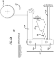
- FIGS. 6A , 6B , and 6C are diagrams, viewed from the right side of the aircraft 210, showing the side view 600, 610, 620 of the TSAS mechanism 400 of FIG. 4 that together illustrate the movement of the TSAS mechanism 400 that occurs during operation of the disclosed system for reducing the probability of the occurrence of an aircraft's tailstrike, in accordance with at least one example of the present disclosure.
- FIG. 6A shows the position of the TSAS mechanism 400 during normal flight control mode (i.e. when the processor(s) determines that the aircraft pitch attitude is not greater than threshold 1, thereby indicating a normal flight control mode where a tailstrike occurrence is not imminent).
- the ball nut 260 of the actuator 250 is extended (i.e. the actuator 250 has not stroked in FIG. 6A ), and the leaf spring 330 is unloaded.
- FIG. 6B shows the position of the TSAS mechanism 400 during the beginning of the activation of a tactile warning (i.e. when the processor(s) determines that the aircraft pitch attitude is greater than threshold 1, thereby indicating that a tailstrike occurrence is imminent).
- the ball nut 260 of the actuator 250 is retracted in the direction of arrow A, which rotates the outer bar 350a (as well as outer bar 350b, the outer bar clevis 350c, and the inner bars 360a, 360b which are not shown in FIG. 6B ) in the same direction.
- FIG. 6C shows the position of the TSAS mechanism 400 during the latter part of the activation of a tactile warning (i.e. when the processor(s) determines that the aircraft pitch attitude is greater than threshold 1, thereby indicating that a tailstrike occurrence is imminent).
- the new position of the outer bar 350a (as well as outer bar 350b and the outer bar clevis 350c, which are not shown in FIG. 6C ) changes the mechanical advantage between the pitch inceptor 310 and the end of the leaf spring 330.
- the pitch inceptor 220a is pulling aftward
- the pitch inceptor 310 rotates in the direction of arrow B (also refer to aft rotation direction arrow B shown in FIG.
- FIG. 7 is a diagram 700, viewed from the left side of the aircraft 210, showing the pilot 720 pulling aft on a typical pitch control inceptor 220a in the cockpit 215 of the aircraft 210, in accordance with at least one example of the present disclosure.
- This figure shows the pilot 720 pulling aft on the pitch control inceptor 220a in the direction of arrow A during a landing or takeoff of the aircraft 210 during a normal flight control mode (i.e. when the processor(s) determines that the aircraft pitch attitude is not greater than threshold 1, thereby indicating a normal flight control mode where a tailstrike occurrence is not imminent).
- FIG. 7 also shows the pitch control inceptor rotation angle ( ⁇ ) of FIG. 8 , in accordance with at least one example of the present disclosure.
- ⁇ pitch control inceptor rotation angle
- FIG. 7 shows that when the pitch control inceptor rotation angle ( ⁇ ) is equal to zero (0) degrees, the pitch control inceptor 220a is positioned in its neutral position (i.e. the pitch control inceptor 220a is neither pulled aft nor pushed forward). As the pitch control inceptor is being pulled aft by the pilot 720, the pitch control inceptor rotation angle ( ⁇ ) increases accordingly in size.
- FIG. 8 is a graph 800 depicting the pitch control inceptor rotation angle ( ⁇ ) versus the pilot input force being applied by the TSAS mechanism 400 versus the amount of actuator stroke by the actuator 250 of the disclosed system for reducing the probability of the occurrence of an aircraft's tailstrike, in accordance with at least one example of the present disclosure.
- the x-axis denotes the pitch control inceptor 220a, 220b rotation angle ( ⁇ ) in degrees.
- the rotation angle ( ⁇ ) is depicted in FIG. 7 .
- the y-axis denotes the amount of pilot input force (i.e. the force in the direction of arrow A of FIG.
- the graph 800 shows three lines, which each indicate a different amount of actuator stroke (refer to FIG. 3C ) in inches. (It should be noted that other amounts of actuator stroke are possible, but are not shown on the graph.)
- the lines on the graph show that as the actuator stroke and the pitch control inceptor rotation angle increases, the pilot 720 will feel an increase in the amount of force ((i.e. the force in the direction of arrow A of FIG. 7 ) on the pitch control inceptor 220a, 220b.
- the lines on the graph show that: (a) the magnitude of the pilot input force is a function of the actuator stroke, (b) the pilot input force is smoothly increased to the pitch control inceptor, (c) the pilot input force is smoothly ramped out when a tailstrike is no longer imminent, and (d) there are at least two distinct force gradients for each actuator stroke.
- FIGS. 9A , 9B , 9C , and 9D together show an additional example for the disclosed system for reducing the probability of the occurrence of an aircraft's tailstrike where a safety mechanism is implemented into the TSAS mechanism (e.g., refer to 400 of FIG. 4 ) to safeguard against the occurrence of foreign object debris (FOD) causing a jam in the linkage mechanism 355 that leads to impeding pilot movement of the pitch control inceptor 220a during normal flight control mode, in accordance with at least one example of the present disclosure.
- these examples illustrate a modification to the design of the TSAS mechanism (refer to 400 of FIG. 4 ) by employing an additional link 391 and fuse 392 to the design.
- the crossbar 390 is modified to integrate a flange 394.
- FIG. 9A is a diagram showing a side view of a portion of the TSAS mechanism that employs the additional link 391 and the fuse 392, in accordance with at least one example of the present disclosure.
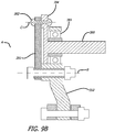
- FIG. 9B is a diagram showing a cut-away front view of a portion of the TSAS mechanism that employs the additional link 391 and the fuse 392, in accordance with at least one example of the present disclosure.
- FOD may enter the linkage mechanism 355 of the TSAS mechanism (e.g., refer to 400 of FIG. 4 ) and cause the linkage mechanism 355 to jam. This will impede pilot movement of the pitch control inceptor 220a.
- FOD refers to any article or substance, alien to an aircraft or system, that can potentially cause damage. The example depicted in FIGS. 9A , 9B , 9C , and 9D mitigates the FOD effect.
- the crossbar 390 which includes a flange 394, (or input member) is connected to the pitch inceptor 310 (or output member) via a link 391, thereby providing torque continuity.
- the upper end of the pitch inceptor 310 is concentrically mounted to the crossbar 390 on a bearing 393, or the like.
- One end of the link 391 is attached to the pitch inceptor 310 at point B.
- the other end of the link 391 is attached to the crossbar 390 by a fuse 392, which could be an aluminum rivet, at point C.
- the angle ⁇ of the link 391 (refer to line CB) relative to a radius of the crossbar 390 and flange 394 (refer line AC) is optimized to obtain the desired shearout torque.
- Point A represents a hinge for rotation between the crossbar 390 and the pitch inceptor 310
- Point B represents a hinge for rotation between the link 391 and the pitch inceptor 310 during the shearing (i.e. breaking off) of fuse 392.
- FIGS. 9C and 9D are diagrams showing a side view of a portion of the TSAS mechanism that employs an additional link 391 with the fuse 392 sheared, in accordance with at least one example of the present disclosure. These diagrams illustrate the ability of the crossbar 390 to rotate freely in the direction of the arrows after the fuse 392 has been sheared, which causes the link 391 to drop down due to gravity.
Landscapes
- Engineering & Computer Science (AREA)
- Aviation & Aerospace Engineering (AREA)
- Automation & Control Theory (AREA)
- Radar, Positioning & Navigation (AREA)
- Remote Sensing (AREA)
- Physics & Mathematics (AREA)
- General Physics & Mathematics (AREA)
- Traffic Control Systems (AREA)
- Emergency Alarm Devices (AREA)
- Measurement Of Mechanical Vibrations Or Ultrasonic Waves (AREA)
Applications Claiming Priority (1)
| Application Number | Priority Date | Filing Date | Title |
|---|---|---|---|
| US15/901,725 US10852747B2 (en) | 2018-02-21 | 2018-02-21 | Tailstrike awareness system |
Publications (2)
| Publication Number | Publication Date |
|---|---|
| EP3530562A1 true EP3530562A1 (de) | 2019-08-28 |
| EP3530562B1 EP3530562B1 (de) | 2024-07-03 |
Family
ID=65529389
Family Applications (1)
| Application Number | Title | Priority Date | Filing Date |
|---|---|---|---|
| EP19158293.1A Active EP3530562B1 (de) | 2018-02-21 | 2019-02-20 | Heckanschlagerkennungssystem |
Country Status (6)
| Country | Link |
|---|---|
| US (1) | US10852747B2 (de) |
| EP (1) | EP3530562B1 (de) |
| JP (1) | JP7261600B2 (de) |
| CN (1) | CN110171574B (de) |
| CA (1) | CA3031830C (de) |
| RU (1) | RU2018145957A (de) |
Families Citing this family (2)
| Publication number | Priority date | Publication date | Assignee | Title |
|---|---|---|---|---|
| CN115675894A (zh) * | 2021-07-27 | 2023-02-03 | 中航西飞民用飞机有限责任公司 | 一种飞机起落架着陆告警系统 |
| US20260004668A1 (en) * | 2024-06-27 | 2026-01-01 | The Boeing Company | Aircraft tail strike detection and prevention system and method |
Citations (4)
| Publication number | Priority date | Publication date | Assignee | Title |
|---|---|---|---|---|
| US8532848B2 (en) * | 2010-10-19 | 2013-09-10 | Honeywell International Inc. | Systems and methods for alerting potential tailstrike during landing |
| EP2821341A1 (de) * | 2013-07-01 | 2015-01-07 | BAE Systems PLC | Steuerorgan und Verfahren zum Betreiben eines Steuerorgans |
| WO2015069228A1 (en) * | 2013-11-05 | 2015-05-14 | Safe Flight Instrument Corporation | Tailstrike warning system |
| US20170305573A1 (en) * | 2015-07-08 | 2017-10-26 | Safe Flight Instrument Corporation | Aircraft turbulence detection |
Family Cites Families (13)
| Publication number | Priority date | Publication date | Assignee | Title |
|---|---|---|---|---|
| FR2708112B1 (fr) * | 1993-07-22 | 1995-09-01 | Ratier Figeac Soc | Dispositif de commande à manche de pilotage, notamment mini-manche asservi pour aéronef. |
| FR2711257B1 (fr) * | 1993-10-14 | 1995-12-22 | Aerospatiale | Système de commande de vol électrique pour avion avec protection en assiette au décollage. |
| US5901927A (en) * | 1996-07-18 | 1999-05-11 | Honeywell Inc. | Ground strike protection function for aircraft autopilot |
| US6422517B1 (en) * | 1999-12-02 | 2002-07-23 | Boeing Company | Aircraft tailstrike avoidance system |
| US6583733B2 (en) * | 2000-05-26 | 2003-06-24 | Honeywell International Inc. | Apparatus, method and computer program product for helicopter ground proximity warning system |
| WO2002023125A1 (en) * | 2000-09-14 | 2002-03-21 | Honeywell International Inc. | Method, apparatus and computer program product for helicopter tail strike warning |
| WO2003008908A1 (en) * | 2001-07-17 | 2003-01-30 | Honeywell International Inc. | Pitch angle alerting device for ground proximity warning system (egpws) |
| US9828113B2 (en) * | 2013-11-05 | 2017-11-28 | Safe Flight Instrument Corporation | Tailstrike warning system |
| FR3021627B1 (fr) * | 2014-05-28 | 2016-06-10 | Airbus Helicopters | Dispositif d'alerte d'un pilote de giravion par signaux tactiles, mettant en oeuvre un "verin de trim" relie a un organe de commande de vol |
| US10227140B2 (en) * | 2014-07-11 | 2019-03-12 | Cmc Electronics Inc | System and method for detecting and alerting the user of an aircraft of an impendent adverse condition |
| US9703293B2 (en) * | 2015-08-31 | 2017-07-11 | The Boeing Company | Aircraft stall protection system |
| US9989972B2 (en) * | 2016-02-22 | 2018-06-05 | The Boeing Company | Systems and methods to prevent an aircraft from tail contact with the ground |
| CN107140221A (zh) * | 2017-03-30 | 2017-09-08 | 中国航空工业集团公司西安飞机设计研究所 | 一种飞机防擦尾装置及具有其的飞机 |
-
2018
- 2018-02-21 US US15/901,725 patent/US10852747B2/en active Active
- 2018-12-24 RU RU2018145957A patent/RU2018145957A/ru unknown
-
2019
- 2019-01-16 CN CN201910038437.7A patent/CN110171574B/zh active Active
- 2019-01-28 CA CA3031830A patent/CA3031830C/en active Active
- 2019-02-07 JP JP2019020619A patent/JP7261600B2/ja active Active
- 2019-02-20 EP EP19158293.1A patent/EP3530562B1/de active Active
Patent Citations (4)
| Publication number | Priority date | Publication date | Assignee | Title |
|---|---|---|---|---|
| US8532848B2 (en) * | 2010-10-19 | 2013-09-10 | Honeywell International Inc. | Systems and methods for alerting potential tailstrike during landing |
| EP2821341A1 (de) * | 2013-07-01 | 2015-01-07 | BAE Systems PLC | Steuerorgan und Verfahren zum Betreiben eines Steuerorgans |
| WO2015069228A1 (en) * | 2013-11-05 | 2015-05-14 | Safe Flight Instrument Corporation | Tailstrike warning system |
| US20170305573A1 (en) * | 2015-07-08 | 2017-10-26 | Safe Flight Instrument Corporation | Aircraft turbulence detection |
Also Published As
| Publication number | Publication date |
|---|---|
| US20190258272A1 (en) | 2019-08-22 |
| EP3530562B1 (de) | 2024-07-03 |
| CN110171574B (zh) | 2024-04-02 |
| JP2019142487A (ja) | 2019-08-29 |
| RU2018145957A3 (de) | 2022-04-21 |
| US10852747B2 (en) | 2020-12-01 |
| BR102019003321A2 (pt) | 2019-09-10 |
| CA3031830A1 (en) | 2019-08-21 |
| RU2018145957A (ru) | 2020-06-25 |
| CN110171574A (zh) | 2019-08-27 |
| CA3031830C (en) | 2023-05-23 |
| JP7261600B2 (ja) | 2023-04-20 |
Similar Documents
| Publication | Publication Date | Title |
|---|---|---|
| US8702035B2 (en) | Actuation apparatus for use on an aircraft | |
| CN109153441B (zh) | 利用从动螺杆驱动双开缝襟翼的装置和方法 | |
| CA3031830C (en) | Tailstrike awareness system | |
| US12337776B2 (en) | Emergency high voltage disconnection device for an electric aircraft | |
| US20200189764A1 (en) | Flight control safety system | |
| US11691517B1 (en) | Emergency high voltage disconnection device for an electric aircraft | |
| Bromfield et al. | Loss of control in flight accident case study: icing-related tailplane stall | |
| CN103640687A (zh) | 一种适用于大展弦比飞机的全动式翼尖阵风减缓装置 | |
| CN107161325A (zh) | 内外襟翼交联装置 | |
| EP4249372A1 (de) | Klappenanordnungen mit ausfall- und blockiersicheren klappenführungen | |
| BR102019003321B1 (pt) | Método para reduzir uma probabilidade de uma ocorrência de um tailstrike para uma aeronave, e aeronave | |
| EP3521157A1 (de) | Flugsteuerungssystem und verfahren für ein luftfahrzeug | |
| Reveley et al. | Causal factors and adverse conditions of aviation accidents and incidents related to integrated resilient aircraft control | |
| EP4532327A1 (de) | Leistungsregeleinheit zum automatisierten regeln eines antriebs sowie luftfahrzeug | |
| DE19930559B4 (de) | Anordnung und Verfahren zum Schutz eines Flugzeugrumpfes | |
| Kasdaglis et al. | Affordant guidance for in-flight loss of control: The Trajectory Recovery System (TRS) | |
| DE602005001468T2 (de) | Steuersystem für die Bremsklappen eines Flugzeugs | |
| CN111114797A (zh) | 一种应急伞降系统及其控制方法 | |
| EP2684797B1 (de) | Flugzeugflügelspitzen-vorrichtung | |
| Arnold | Role of pilot lack of manual control proficiency in air transport aircraft accidents | |
| JP7778025B2 (ja) | ヘリコプター送信機アンテナシャフト部の折れ機構 | |
| Bing et al. | Validation for civil aircraft landing gear failure condition by case analysis of aviation incident | |
| EP4491510A1 (de) | Einzelklappenantriebssystem für dezentralisierte klappenarchitekturen | |
| Chevalier et al. | A Stall/Spin Prevention Device for General-Aviation Aircraft | |
| Burnside | Full Deflection? Heeding maneuvering speed protects against gusts or abrupt control movement. What if they're combined? |
Legal Events
| Date | Code | Title | Description |
|---|---|---|---|
| PUAI | Public reference made under article 153(3) epc to a published international application that has entered the european phase |
Free format text: ORIGINAL CODE: 0009012 |
|
| STAA | Information on the status of an ep patent application or granted ep patent |
Free format text: STATUS: REQUEST FOR EXAMINATION WAS MADE |
|
| 17P | Request for examination filed |
Effective date: 20190220 |
|
| AK | Designated contracting states |
Kind code of ref document: A1 Designated state(s): AL AT BE BG CH CY CZ DE DK EE ES FI FR GB GR HR HU IE IS IT LI LT LU LV MC MK MT NL NO PL PT RO RS SE SI SK SM TR |
|
| AX | Request for extension of the european patent |
Extension state: BA ME |
|
| STAA | Information on the status of an ep patent application or granted ep patent |
Free format text: STATUS: EXAMINATION IS IN PROGRESS |
|
| RIC1 | Information provided on ipc code assigned before grant |
Ipc: B64C 13/10 20060101AFI20210430BHEP Ipc: B64D 43/00 20060101ALI20210430BHEP Ipc: B64D 45/00 20060101ALI20210430BHEP Ipc: B64D 45/04 20060101ALI20210430BHEP |
|
| 17Q | First examination report despatched |
Effective date: 20210527 |
|
| RAP3 | Party data changed (applicant data changed or rights of an application transferred) |
Owner name: THE BOEING COMPANY |
|
| GRAP | Despatch of communication of intention to grant a patent |
Free format text: ORIGINAL CODE: EPIDOSNIGR1 |
|
| STAA | Information on the status of an ep patent application or granted ep patent |
Free format text: STATUS: GRANT OF PATENT IS INTENDED |
|
| INTG | Intention to grant announced |
Effective date: 20240216 |
|
| P01 | Opt-out of the competence of the unified patent court (upc) registered |
Effective date: 20240301 |
|
| GRAS | Grant fee paid |
Free format text: ORIGINAL CODE: EPIDOSNIGR3 |
|
| GRAA | (expected) grant |
Free format text: ORIGINAL CODE: 0009210 |
|
| STAA | Information on the status of an ep patent application or granted ep patent |
Free format text: STATUS: THE PATENT HAS BEEN GRANTED |
|
| AK | Designated contracting states |
Kind code of ref document: B1 Designated state(s): AL AT BE BG CH CY CZ DE DK EE ES FI FR GB GR HR HU IE IS IT LI LT LU LV MC MK MT NL NO PL PT RO RS SE SI SK SM TR |
|
| REG | Reference to a national code |
Ref country code: CH Ref legal event code: EP |
|
| REG | Reference to a national code |
Ref country code: DE Ref legal event code: R096 Ref document number: 602019054449 Country of ref document: DE |
|
| REG | Reference to a national code |
Ref country code: LT Ref legal event code: MG9D |
|
| REG | Reference to a national code |
Ref country code: NL Ref legal event code: MP Effective date: 20240703 |
|
| PG25 | Lapsed in a contracting state [announced via postgrant information from national office to epo] |
Ref country code: PT Free format text: LAPSE BECAUSE OF FAILURE TO SUBMIT A TRANSLATION OF THE DESCRIPTION OR TO PAY THE FEE WITHIN THE PRESCRIBED TIME-LIMIT Effective date: 20241104 |
|
| REG | Reference to a national code |
Ref country code: AT Ref legal event code: MK05 Ref document number: 1699573 Country of ref document: AT Kind code of ref document: T Effective date: 20240703 |
|
| PG25 | Lapsed in a contracting state [announced via postgrant information from national office to epo] |
Ref country code: NL Free format text: LAPSE BECAUSE OF FAILURE TO SUBMIT A TRANSLATION OF THE DESCRIPTION OR TO PAY THE FEE WITHIN THE PRESCRIBED TIME-LIMIT Effective date: 20240703 |
|
| PG25 | Lapsed in a contracting state [announced via postgrant information from national office to epo] |
Ref country code: PT Free format text: LAPSE BECAUSE OF FAILURE TO SUBMIT A TRANSLATION OF THE DESCRIPTION OR TO PAY THE FEE WITHIN THE PRESCRIBED TIME-LIMIT Effective date: 20241104 Ref country code: NL Free format text: LAPSE BECAUSE OF FAILURE TO SUBMIT A TRANSLATION OF THE DESCRIPTION OR TO PAY THE FEE WITHIN THE PRESCRIBED TIME-LIMIT Effective date: 20240703 |
|
| PG25 | Lapsed in a contracting state [announced via postgrant information from national office to epo] |
Ref country code: NO Free format text: LAPSE BECAUSE OF FAILURE TO SUBMIT A TRANSLATION OF THE DESCRIPTION OR TO PAY THE FEE WITHIN THE PRESCRIBED TIME-LIMIT Effective date: 20241003 |
|
| PG25 | Lapsed in a contracting state [announced via postgrant information from national office to epo] |
Ref country code: GR Free format text: LAPSE BECAUSE OF FAILURE TO SUBMIT A TRANSLATION OF THE DESCRIPTION OR TO PAY THE FEE WITHIN THE PRESCRIBED TIME-LIMIT Effective date: 20241004 Ref country code: FI Free format text: LAPSE BECAUSE OF FAILURE TO SUBMIT A TRANSLATION OF THE DESCRIPTION OR TO PAY THE FEE WITHIN THE PRESCRIBED TIME-LIMIT Effective date: 20240703 Ref country code: PL Free format text: LAPSE BECAUSE OF FAILURE TO SUBMIT A TRANSLATION OF THE DESCRIPTION OR TO PAY THE FEE WITHIN THE PRESCRIBED TIME-LIMIT Effective date: 20240703 |
|
| PG25 | Lapsed in a contracting state [announced via postgrant information from national office to epo] |
Ref country code: BG Free format text: LAPSE BECAUSE OF FAILURE TO SUBMIT A TRANSLATION OF THE DESCRIPTION OR TO PAY THE FEE WITHIN THE PRESCRIBED TIME-LIMIT Effective date: 20240703 |
|
| PG25 | Lapsed in a contracting state [announced via postgrant information from national office to epo] |
Ref country code: LV Free format text: LAPSE BECAUSE OF FAILURE TO SUBMIT A TRANSLATION OF THE DESCRIPTION OR TO PAY THE FEE WITHIN THE PRESCRIBED TIME-LIMIT Effective date: 20240703 |
|
| PG25 | Lapsed in a contracting state [announced via postgrant information from national office to epo] |
Ref country code: IS Free format text: LAPSE BECAUSE OF FAILURE TO SUBMIT A TRANSLATION OF THE DESCRIPTION OR TO PAY THE FEE WITHIN THE PRESCRIBED TIME-LIMIT Effective date: 20241103 Ref country code: AT Free format text: LAPSE BECAUSE OF FAILURE TO SUBMIT A TRANSLATION OF THE DESCRIPTION OR TO PAY THE FEE WITHIN THE PRESCRIBED TIME-LIMIT Effective date: 20240703 |
|
| PG25 | Lapsed in a contracting state [announced via postgrant information from national office to epo] |
Ref country code: CZ Free format text: LAPSE BECAUSE OF FAILURE TO SUBMIT A TRANSLATION OF THE DESCRIPTION OR TO PAY THE FEE WITHIN THE PRESCRIBED TIME-LIMIT Effective date: 20240703 Ref country code: HR Free format text: LAPSE BECAUSE OF FAILURE TO SUBMIT A TRANSLATION OF THE DESCRIPTION OR TO PAY THE FEE WITHIN THE PRESCRIBED TIME-LIMIT Effective date: 20240703 |
|
| PG25 | Lapsed in a contracting state [announced via postgrant information from national office to epo] |
Ref country code: RS Free format text: LAPSE BECAUSE OF FAILURE TO SUBMIT A TRANSLATION OF THE DESCRIPTION OR TO PAY THE FEE WITHIN THE PRESCRIBED TIME-LIMIT Effective date: 20241003 Ref country code: ES Free format text: LAPSE BECAUSE OF FAILURE TO SUBMIT A TRANSLATION OF THE DESCRIPTION OR TO PAY THE FEE WITHIN THE PRESCRIBED TIME-LIMIT Effective date: 20240703 |
|
| PG25 | Lapsed in a contracting state [announced via postgrant information from national office to epo] |
Ref country code: RS Free format text: LAPSE BECAUSE OF FAILURE TO SUBMIT A TRANSLATION OF THE DESCRIPTION OR TO PAY THE FEE WITHIN THE PRESCRIBED TIME-LIMIT Effective date: 20241003 Ref country code: PL Free format text: LAPSE BECAUSE OF FAILURE TO SUBMIT A TRANSLATION OF THE DESCRIPTION OR TO PAY THE FEE WITHIN THE PRESCRIBED TIME-LIMIT Effective date: 20240703 Ref country code: NO Free format text: LAPSE BECAUSE OF FAILURE TO SUBMIT A TRANSLATION OF THE DESCRIPTION OR TO PAY THE FEE WITHIN THE PRESCRIBED TIME-LIMIT Effective date: 20241003 Ref country code: LV Free format text: LAPSE BECAUSE OF FAILURE TO SUBMIT A TRANSLATION OF THE DESCRIPTION OR TO PAY THE FEE WITHIN THE PRESCRIBED TIME-LIMIT Effective date: 20240703 Ref country code: IS Free format text: LAPSE BECAUSE OF FAILURE TO SUBMIT A TRANSLATION OF THE DESCRIPTION OR TO PAY THE FEE WITHIN THE PRESCRIBED TIME-LIMIT Effective date: 20241103 Ref country code: HR Free format text: LAPSE BECAUSE OF FAILURE TO SUBMIT A TRANSLATION OF THE DESCRIPTION OR TO PAY THE FEE WITHIN THE PRESCRIBED TIME-LIMIT Effective date: 20240703 Ref country code: GR Free format text: LAPSE BECAUSE OF FAILURE TO SUBMIT A TRANSLATION OF THE DESCRIPTION OR TO PAY THE FEE WITHIN THE PRESCRIBED TIME-LIMIT Effective date: 20241004 Ref country code: FI Free format text: LAPSE BECAUSE OF FAILURE TO SUBMIT A TRANSLATION OF THE DESCRIPTION OR TO PAY THE FEE WITHIN THE PRESCRIBED TIME-LIMIT Effective date: 20240703 Ref country code: ES Free format text: LAPSE BECAUSE OF FAILURE TO SUBMIT A TRANSLATION OF THE DESCRIPTION OR TO PAY THE FEE WITHIN THE PRESCRIBED TIME-LIMIT Effective date: 20240703 Ref country code: CZ Free format text: LAPSE BECAUSE OF FAILURE TO SUBMIT A TRANSLATION OF THE DESCRIPTION OR TO PAY THE FEE WITHIN THE PRESCRIBED TIME-LIMIT Effective date: 20240703 Ref country code: BG Free format text: LAPSE BECAUSE OF FAILURE TO SUBMIT A TRANSLATION OF THE DESCRIPTION OR TO PAY THE FEE WITHIN THE PRESCRIBED TIME-LIMIT Effective date: 20240703 Ref country code: AT Free format text: LAPSE BECAUSE OF FAILURE TO SUBMIT A TRANSLATION OF THE DESCRIPTION OR TO PAY THE FEE WITHIN THE PRESCRIBED TIME-LIMIT Effective date: 20240703 |
|
| REG | Reference to a national code |
Ref country code: DE Ref legal event code: R097 Ref document number: 602019054449 Country of ref document: DE |
|
| PG25 | Lapsed in a contracting state [announced via postgrant information from national office to epo] |
Ref country code: RO Free format text: LAPSE BECAUSE OF FAILURE TO SUBMIT A TRANSLATION OF THE DESCRIPTION OR TO PAY THE FEE WITHIN THE PRESCRIBED TIME-LIMIT Effective date: 20240703 Ref country code: DK Free format text: LAPSE BECAUSE OF FAILURE TO SUBMIT A TRANSLATION OF THE DESCRIPTION OR TO PAY THE FEE WITHIN THE PRESCRIBED TIME-LIMIT Effective date: 20240703 Ref country code: SM Free format text: LAPSE BECAUSE OF FAILURE TO SUBMIT A TRANSLATION OF THE DESCRIPTION OR TO PAY THE FEE WITHIN THE PRESCRIBED TIME-LIMIT Effective date: 20240703 |
|
| PG25 | Lapsed in a contracting state [announced via postgrant information from national office to epo] |
Ref country code: EE Free format text: LAPSE BECAUSE OF FAILURE TO SUBMIT A TRANSLATION OF THE DESCRIPTION OR TO PAY THE FEE WITHIN THE PRESCRIBED TIME-LIMIT Effective date: 20240703 |
|
| PG25 | Lapsed in a contracting state [announced via postgrant information from national office to epo] |
Ref country code: IT Free format text: LAPSE BECAUSE OF FAILURE TO SUBMIT A TRANSLATION OF THE DESCRIPTION OR TO PAY THE FEE WITHIN THE PRESCRIBED TIME-LIMIT Effective date: 20240703 Ref country code: SK Free format text: LAPSE BECAUSE OF FAILURE TO SUBMIT A TRANSLATION OF THE DESCRIPTION OR TO PAY THE FEE WITHIN THE PRESCRIBED TIME-LIMIT Effective date: 20240703 |
|
| PLBE | No opposition filed within time limit |
Free format text: ORIGINAL CODE: 0009261 |
|
| STAA | Information on the status of an ep patent application or granted ep patent |
Free format text: STATUS: NO OPPOSITION FILED WITHIN TIME LIMIT |
|
| 26N | No opposition filed |
Effective date: 20250404 |
|
| PG25 | Lapsed in a contracting state [announced via postgrant information from national office to epo] |
Ref country code: SE Free format text: LAPSE BECAUSE OF FAILURE TO SUBMIT A TRANSLATION OF THE DESCRIPTION OR TO PAY THE FEE WITHIN THE PRESCRIBED TIME-LIMIT Effective date: 20240703 |
|
| PG25 | Lapsed in a contracting state [announced via postgrant information from national office to epo] |
Ref country code: MC Free format text: LAPSE BECAUSE OF FAILURE TO SUBMIT A TRANSLATION OF THE DESCRIPTION OR TO PAY THE FEE WITHIN THE PRESCRIBED TIME-LIMIT Effective date: 20240703 |
|
| REG | Reference to a national code |
Ref country code: CH Ref legal event code: PL |
|
| PG25 | Lapsed in a contracting state [announced via postgrant information from national office to epo] |
Ref country code: LU Free format text: LAPSE BECAUSE OF NON-PAYMENT OF DUE FEES Effective date: 20250220 |
|
| PG25 | Lapsed in a contracting state [announced via postgrant information from national office to epo] |
Ref country code: CH Free format text: LAPSE BECAUSE OF NON-PAYMENT OF DUE FEES Effective date: 20250228 |
|
| REG | Reference to a national code |
Ref country code: BE Ref legal event code: MM Effective date: 20250228 |
|
| PG25 | Lapsed in a contracting state [announced via postgrant information from national office to epo] |
Ref country code: BE Free format text: LAPSE BECAUSE OF NON-PAYMENT OF DUE FEES Effective date: 20250228 |
|
| PG25 | Lapsed in a contracting state [announced via postgrant information from national office to epo] |
Ref country code: IE Free format text: LAPSE BECAUSE OF NON-PAYMENT OF DUE FEES Effective date: 20250220 |
|
| PGFP | Annual fee paid to national office [announced via postgrant information from national office to epo] |
Ref country code: GB Payment date: 20260227 Year of fee payment: 8 |
|
| PGFP | Annual fee paid to national office [announced via postgrant information from national office to epo] |
Ref country code: DE Payment date: 20260227 Year of fee payment: 8 |
|
| PGFP | Annual fee paid to national office [announced via postgrant information from national office to epo] |
Ref country code: FR Payment date: 20260225 Year of fee payment: 8 |