EP3530962A1 - Procédé de commande d'une pression de descente d'un levage assisté électrohydraulique et levage électrohydraulique - Google Patents
Procédé de commande d'une pression de descente d'un levage assisté électrohydraulique et levage électrohydraulique Download PDFInfo
- Publication number
- EP3530962A1 EP3530962A1 EP19158718.7A EP19158718A EP3530962A1 EP 3530962 A1 EP3530962 A1 EP 3530962A1 EP 19158718 A EP19158718 A EP 19158718A EP 3530962 A1 EP3530962 A1 EP 3530962A1
- Authority
- EP
- European Patent Office
- Prior art keywords
- pressure
- valve
- lifting
- sink
- piston
- Prior art date
- Legal status (The legal status is an assumption and is not a legal conclusion. Google has not performed a legal analysis and makes no representation as to the accuracy of the status listed.)
- Granted
Links
Images


Classifications
-
- F—MECHANICAL ENGINEERING; LIGHTING; HEATING; WEAPONS; BLASTING
- F15—FLUID-PRESSURE ACTUATORS; HYDRAULICS OR PNEUMATICS IN GENERAL
- F15B—SYSTEMS ACTING BY MEANS OF FLUIDS IN GENERAL; FLUID-PRESSURE ACTUATORS, e.g. SERVOMOTORS; DETAILS OF FLUID-PRESSURE SYSTEMS, NOT OTHERWISE PROVIDED FOR
- F15B11/00—Servomotor systems without provision for follow-up action; Circuits therefor
- F15B11/02—Systems essentially incorporating special features for controlling the speed or actuating force of an output member
- F15B11/028—Systems essentially incorporating special features for controlling the speed or actuating force of an output member for controlling the actuating force
-
- F—MECHANICAL ENGINEERING; LIGHTING; HEATING; WEAPONS; BLASTING
- F15—FLUID-PRESSURE ACTUATORS; HYDRAULICS OR PNEUMATICS IN GENERAL
- F15B—SYSTEMS ACTING BY MEANS OF FLUIDS IN GENERAL; FLUID-PRESSURE ACTUATORS, e.g. SERVOMOTORS; DETAILS OF FLUID-PRESSURE SYSTEMS, NOT OTHERWISE PROVIDED FOR
- F15B2211/00—Circuits for servomotor systems
- F15B2211/50—Pressure control
- F15B2211/505—Pressure control characterised by the type of pressure control means
- F15B2211/50554—Pressure control characterised by the type of pressure control means the pressure control means controlling a pressure downstream of the pressure control means, e.g. pressure reducing valve
-
- F—MECHANICAL ENGINEERING; LIGHTING; HEATING; WEAPONS; BLASTING
- F15—FLUID-PRESSURE ACTUATORS; HYDRAULICS OR PNEUMATICS IN GENERAL
- F15B—SYSTEMS ACTING BY MEANS OF FLUIDS IN GENERAL; FLUID-PRESSURE ACTUATORS, e.g. SERVOMOTORS; DETAILS OF FLUID-PRESSURE SYSTEMS, NOT OTHERWISE PROVIDED FOR
- F15B2211/00—Circuits for servomotor systems
- F15B2211/50—Pressure control
- F15B2211/515—Pressure control characterised by the connections of the pressure control means in the circuit
- F15B2211/5158—Pressure control characterised by the connections of the pressure control means in the circuit being connected to a pressure source and an output member
-
- F—MECHANICAL ENGINEERING; LIGHTING; HEATING; WEAPONS; BLASTING
- F15—FLUID-PRESSURE ACTUATORS; HYDRAULICS OR PNEUMATICS IN GENERAL
- F15B—SYSTEMS ACTING BY MEANS OF FLUIDS IN GENERAL; FLUID-PRESSURE ACTUATORS, e.g. SERVOMOTORS; DETAILS OF FLUID-PRESSURE SYSTEMS, NOT OTHERWISE PROVIDED FOR
- F15B2211/00—Circuits for servomotor systems
- F15B2211/50—Pressure control
- F15B2211/52—Pressure control characterised by the type of actuation
- F15B2211/526—Pressure control characterised by the type of actuation electrically or electronically
-
- F—MECHANICAL ENGINEERING; LIGHTING; HEATING; WEAPONS; BLASTING
- F15—FLUID-PRESSURE ACTUATORS; HYDRAULICS OR PNEUMATICS IN GENERAL
- F15B—SYSTEMS ACTING BY MEANS OF FLUIDS IN GENERAL; FLUID-PRESSURE ACTUATORS, e.g. SERVOMOTORS; DETAILS OF FLUID-PRESSURE SYSTEMS, NOT OTHERWISE PROVIDED FOR
- F15B2211/00—Circuits for servomotor systems
- F15B2211/60—Circuit components or control therefor
- F15B2211/63—Electronic controllers
- F15B2211/6303—Electronic controllers using input signals
- F15B2211/6306—Electronic controllers using input signals representing a pressure
- F15B2211/6313—Electronic controllers using input signals representing a pressure the pressure being a load pressure
-
- F—MECHANICAL ENGINEERING; LIGHTING; HEATING; WEAPONS; BLASTING
- F15—FLUID-PRESSURE ACTUATORS; HYDRAULICS OR PNEUMATICS IN GENERAL
- F15B—SYSTEMS ACTING BY MEANS OF FLUIDS IN GENERAL; FLUID-PRESSURE ACTUATORS, e.g. SERVOMOTORS; DETAILS OF FLUID-PRESSURE SYSTEMS, NOT OTHERWISE PROVIDED FOR
- F15B2211/00—Circuits for servomotor systems
- F15B2211/60—Circuit components or control therefor
- F15B2211/665—Methods of control using electronic components
-
- F—MECHANICAL ENGINEERING; LIGHTING; HEATING; WEAPONS; BLASTING
- F15—FLUID-PRESSURE ACTUATORS; HYDRAULICS OR PNEUMATICS IN GENERAL
- F15B—SYSTEMS ACTING BY MEANS OF FLUIDS IN GENERAL; FLUID-PRESSURE ACTUATORS, e.g. SERVOMOTORS; DETAILS OF FLUID-PRESSURE SYSTEMS, NOT OTHERWISE PROVIDED FOR
- F15B2211/00—Circuits for servomotor systems
- F15B2211/60—Circuit components or control therefor
- F15B2211/665—Methods of control using electronic components
- F15B2211/6653—Pressure control
-
- F—MECHANICAL ENGINEERING; LIGHTING; HEATING; WEAPONS; BLASTING
- F15—FLUID-PRESSURE ACTUATORS; HYDRAULICS OR PNEUMATICS IN GENERAL
- F15B—SYSTEMS ACTING BY MEANS OF FLUIDS IN GENERAL; FLUID-PRESSURE ACTUATORS, e.g. SERVOMOTORS; DETAILS OF FLUID-PRESSURE SYSTEMS, NOT OTHERWISE PROVIDED FOR
- F15B2211/00—Circuits for servomotor systems
- F15B2211/70—Output members, e.g. hydraulic motors or cylinders or control therefor
- F15B2211/705—Output members, e.g. hydraulic motors or cylinders or control therefor characterised by the type of output members or actuators
- F15B2211/7051—Linear output members
- F15B2211/7053—Double-acting output members
-
- F—MECHANICAL ENGINEERING; LIGHTING; HEATING; WEAPONS; BLASTING
- F15—FLUID-PRESSURE ACTUATORS; HYDRAULICS OR PNEUMATICS IN GENERAL
- F15B—SYSTEMS ACTING BY MEANS OF FLUIDS IN GENERAL; FLUID-PRESSURE ACTUATORS, e.g. SERVOMOTORS; DETAILS OF FLUID-PRESSURE SYSTEMS, NOT OTHERWISE PROVIDED FOR
- F15B2211/00—Circuits for servomotor systems
- F15B2211/70—Output members, e.g. hydraulic motors or cylinders or control therefor
- F15B2211/76—Control of force or torque of the output member
Definitions
- the invention relates to a method for controlling a sinking pressure of an electro-hydraulic power lift, the at least one working cylinder with a piston, with a lifting side, which limits the piston with a lift-side effective area, which is supplied for lifting a load pressure medium and in which a lifting pressure is present, and having a drain side, which limits the piston with a sink-side effective area, which is supplied to lower a load pressure medium and in which the depression pressure is present.
- the electrohydraulic power lift further comprises a first pressure sensor for detecting the lifting pressure and a second pressure sensor for detecting the lowering pressure, an adjustable pressure valve for setting a lowering pressure and an electronic control unit to which the pressures detected by the pressure sensors are supplied and from which the pressure valve can be controlled.
- the lifting side and the sink side can be compared to in the EP 2 884 118 also be reversed arrangement shown.
- the bottom side Cylinder space the lifting side while in front loaders usually the rod-side cylinder chamber is the lifting side.
- the from the EP 2 884 118 A1 known electro-hydraulic power lift has an adjustable pressure control valve associated with the drain side, with which a certain pressure can be regulated on the drain side.
- a pressure sensor is provided with which the pressure on the lifting side can be detected. It is intended to determine with the pressure sensor certain operating situations, for example, an excessive pressure on the lifting side or a pressure drop on the lifting side and then to change the control of the pressure regulating valve.
- the invention has for its object to provide a method by which the operation of an electro-hydraulic power lift is improved with the features specified.
- the following method steps are provided: Continuously determining an equivalent depression pressure by forming the difference between the stroke pressure multiplied by k as minuend and the depression pressure as subtrahend in the electronic control unit, where k is the ratio of the magnitude of the lift side effective area to the size of the sink side effective area of the piston, forming a pressure value as the difference between a target pressure set on the control unit on the sink side as Minuend and the equivalent sink pressure as subtrahend and control of the pressure valve with a drive signal corresponding to the pressure value.
- the equivalent lowering pressure is set equal to zero for the formation of the pressure value if the current determination of the equivalent depression pressure results in a negative value.
- the pressure valve is advantageously driven in accordance with the lowest pressure that can be set on it. Usually then the pressure valve is not activated. Unless it is a pressure valve with a negative characteristic, like one in the EP 2 884 118 A1 is shown.
- the pressure setting on the drain side can be further improved by the fact that the control signal for the pressure valve is increased or decreased depending on the current volume flow and its sign to compensate for a pressure drop caused by flow-volume pressure between the pressure valve and the sink side.
- the drive signal for the pressure valve can be increased or decreased according to a characteristic curve. It is also possible to increase or decrease according to a factor.
- the electrohydraulic power lift comprises a load-compensated LS directional control valve which can be connected to the lifting side of the working cylinder, then a volume flow flowing between the pressure valve and the sink side of the working cylinder, in particular a volume flow flowing away from the sink side, can be detected via the activation signal with which the LS (load sensing) - Directional valve is controlled to be determined.
- the lifting mode is suitable because the lifting usually done load compensated via the LS-way valve and the control signal as given to the LS-way valve set volume flow corresponds to the actual volume flow, as long as no stop reached or limits the hydraulic energy is and is delivered by a pump not as much pressure medium quantity as requested.
- a volume flow flowing between the pressure valve and the drain side of the working cylinder can also be determined via the derivation of the signal of a displacement sensor associated with the working cylinder. This is especially advantageous in a sink, as this is an overpressure is excluded. The pressure value is only increased if a volume flow also flows.
- control unit Depending on the sign and / or amount of the determined equivalent sink pressure different set pressures can be specified by the control unit.
- a shut-off valve can be arranged and from the drain side of the working cylinder pressure medium can be discharged, bypassing the pressure valve via a relief valve. It may be beneficial if the shut-off valve is closed and the relief valve is opened when the target volume flow to the lifting side and thus the setpoint speed for lifting exceeds a certain value and the pressure value falls below a certain value.
- the pressure valve is preferably a pressure regulating valve.
- a pressure control valve usually has a with a hydraulic consumer - here with the sink side of the working cylinder - connected consumer port, a pressure port and a tank connection and is able to flow pressure fluid both to the hydraulic consumer to allow pressure control and to drain from the hydraulic consumer.
- the invention is also realized in an electrohydraulic power lift, the at least one working cylinder with a piston, with a lifting side, which limits the piston with a lifting side effective surface, which is supplied for lifting a load pressure medium and in which a lifting pressure is present, and with a sink side that limits the piston with a sink-side effective area, which is supplied to lower a load pressure medium and in which the depression pressure is present, a first pressure sensor for detecting the lifting pressure and a second pressure sensor for detecting the sink pressure, an adjustable pressure valve for setting a sinking pressure and a electronic control unit, which are supplied to the pressure detected by the pressure sensors and from which the pressure valve is controllable, wherein the electronic control unit is adapted to carry out a method as described above.
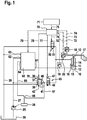
- FIG. 1 the rear-mounted hoist on a tractor and has a working cylinder 10.
- a piston 11 In the interior of a housing of the working cylinder, a piston 11 is movable on which one side a piston rod 12 is fixed, which at one end, the so-called head of the working cylinder emerges from the housing.
- the piston and the piston rod are a rod-side or bottom-side cylinder chamber 13 and a rod-side, annular cylinder chamber 14 are formed and separated from each other.
- pressure medium is supplied to the bottom-side cylinder chamber 13 for lowering and to the cylinder-side cylinder chamber 14 for lowering.
- the bottom-side cylinder space thus represents the lifting side and the rod-side cylinder chamber the sink side of the working cylinder.
- the free end of the piston rod 12 is connected via attached to the tractor lifting arms 17 with an attachment, which is shown here as a plow.
- the connection is drawn in a very schematic way.
- the position occupied by the lifting arms 17 are detected by a position sensor 18 and converted into an electrical signal.
- the pressure in the cylinder chamber 13 can be detected by a first pressure sensor 19.
- the pressure in the cylinder chamber 14 can be detected by a second pressure sensor 20 which, like the first pressure sensor, converts the pressure into an electrical signal.
- the electrohydraulic power lift shown also has a load-sensing regulated variable displacement pump 25, which sucks pressure medium from a tank 26 and discharges into a pump line 27.
- Controlled load-sensing means that the variable displacement respectively promotes so much pressure medium, that the pressure in the pump line 27 is a certain pressure difference across a reported to the load-sensing controller 28 of the variable displacement control pressure, the usually the highest load pressure of all simultaneously supplied with pressure medium hydraulic consumer.
- a pressure control valve 35 which is proportionally adjustable by means of a proportional solenoid 36 is connected to a pressure port 37 to the pump line 27 and a discharge port 38 to a tank line 39, via the pressure medium from the hydraulic consumers of the tractor, in particular from the working cylinder 10th flows back to the tank 26.
- the pressure at a control connection 40 of the pressure regulating valve which can be connected to the rod-side cylinder chamber 14 is fed back to a measuring surface on the pressure regulating valve via a control line 41 and generates a force on the measuring surface which acts against the force of the proportional solenoid 36 together with a force exerted by a control spring 42 ,
- a control connection 40 of the pressure regulating valve in each case, such a pressure is established that a balance exists between the opposing forces. Since the pressure force and the magnetic force act against each other, pressure control valve 35 has a positive characteristic. The control pressure thus increases with the current flowing through the electromagnet 36 current.
- the pressure control valve 35 is shown as a directly controlled pressure control valve. However, it can also be used a pilot-operated pressure control valve.
- a check valve 45 is arranged, which is designed as a 2/2-way seat valve, under the action of a return spring 46 assumes its blocking position in which the connection between the control port 40 and the cylinder chamber fourteenth is interrupted, and can be brought by a solenoid 47 against the force of the return spring 46 in a passage position in which the connection between the control port 40 and the cylinder chamber 14 is open.
- a relief valve 50 is arranged, which is formed as the valve 45 as a 2/2-way seat valve, under the action of a return spring 51 assumes its blocking position, in which the connection between the tank line 39 and the cylinder chamber 14 is interrupted, and can be brought by a solenoid 52 against the force of the return spring 51 in a passage position in which the connection between the cylinder chamber 14 and the tank line 39 is open.
- the relief valve 50 is used in certain operating conditions for complete pressure relief of the rod-side cylinder chamber 14. When the relief valve 50 is open, then the check valve 45 is closed. When the shut-off valve 45 is open, the relief valve 50 is closed.
- the Hubtechniksregelventilan Aunt 60 includes an individual pressure compensator, not shown, the pressure drop across keeps an adjustable metering orifice constant, so that the pressure medium flowing through the metering orifice depends only on the instantaneous flow cross section of the metering orifice.
- the outflow of pressure medium from the cylinder chamber 13 is not controlled load pressure independent.
- the Hubtechniksventilan Aunt 60 also has a load-sensing connection 64 from which a control line 65 leads to a first input of a shuttle valve 66.
- the second input of the shuttle valve 66 is connected via a control line 67 to the control port 40 of the pressure control valve 35.
- the output of the shuttle valve 66 is connected to the load-sensing controller 28 of the variable displacement pump 25.
- the load-sensing controller 28 so the higher of the pending in the cylinder chambers 13 and 14 pressures is reported.
- An electronic control unit 70 is provided, which is supplied with the electrical signals of the position sensor 18, the two pressure sensors 19 and 20 and a desired electrical signal, which is generated by means of a control element 71, via electrical lines 72, 73, 74 and 75.
- the electronic control unit calculates from the supplied electrical signals drive signals for the electromagnets of the pressure control valve 35, the check valve 45, the relief valve 50 and the Hubtechniksventilan Aunt 60 and controls the electromagnets via electrical lines 76, 77, 78 and 79 accordingly.
- An equivalent lowering pressure is continuously detected by the electronic control unit 70 by subtracting the difference between the lifting pressure (DS carrying) multiplied by k and detected by the pressure sensor 19 as Minuend and the lowering pressure (DS pressing) detected by the pressure sensor 20.
- the equivalent depression pressure is therefore 200 bar by 1.25 - 0 equal to 250 bar.
- the calculated equivalent depression pressures (differential pressure (bearing * k - pressures)) are filtered using a low-pass filter. If the equivalent depression pressure is positive (positive limit), a pressure value is determined as the difference between the target pressure transmitted by the control element 71 and stored there to the control unit 70 and stored there as a minuend and the equivalent depression pressure as a subtrahend.
- the equivalent depression pressure is negative, a value 0 for the equivalent depression pressure is assumed for the determination of the pressure value.
- the equivalent sink pressure is minus 250 bar.
- 50 bar minus 0 equals 50 bar.
- the electronic control unit 70 does not control the pressure regulating valve 35 to be at the smallest setting. None changes until the plow hits the ground.
- the support pressure now decreases.
- the electronic control unit begins to control the pressure control valve 35 with a drive signal greater than zero when the support pressure has dropped to 40 bar. From this time, the control signal for the pressure control valve 35 (static DRV setpoint) rises to the setpoint of 50 bar.
- the method according to FIG. 2 can be supplemented by a volumetric flow compensation, as in two alternatives in the Figures 3 and 4 is shown.
- a volumetric flow compensation as in two alternatives in the Figures 3 and 4 is shown.
- P-gain proportionality factor
- the correction value is subtracted from the static setpoint for the pressure control valve (static DRV setpoint). If the difference is positive, it is equal to a dynamic setpoint for the pressure control valve 35 in lifting.
- the volume flow which is displaced during lifting from the rod-side cylinder chamber 14, can be determined from the drive signal for the electro-hydraulic lifting valve arrangement, which is a measure of the cylinder chamber 13 inflowing pressure medium quantity, and the area ratio k of the working cylinder 10.
Landscapes
- Engineering & Computer Science (AREA)
- Physics & Mathematics (AREA)
- Fluid Mechanics (AREA)
- Mechanical Engineering (AREA)
- General Engineering & Computer Science (AREA)
- Fluid-Pressure Circuits (AREA)
Applications Claiming Priority (2)
| Application Number | Priority Date | Filing Date | Title |
|---|---|---|---|
| DE102018202899 | 2018-02-27 | ||
| DE102018204568.2A DE102018204568A1 (de) | 2018-02-27 | 2018-03-26 | Verfahren zur Steuerung eines Senkendrucks eines elektrohydraulischen Krafthebers und elektrohydraulischer Kraftheber |
Publications (2)
| Publication Number | Publication Date |
|---|---|
| EP3530962A1 true EP3530962A1 (fr) | 2019-08-28 |
| EP3530962B1 EP3530962B1 (fr) | 2024-05-29 |
Family
ID=65598428
Family Applications (1)
| Application Number | Title | Priority Date | Filing Date |
|---|---|---|---|
| EP19158718.7A Active EP3530962B1 (fr) | 2018-02-27 | 2019-02-22 | Procédé de commande d'une pression de descente d'un levage assisté électrohydraulique et levage électrohydraulique |
Country Status (1)
| Country | Link |
|---|---|
| EP (1) | EP3530962B1 (fr) |
Cited By (1)
| Publication number | Priority date | Publication date | Assignee | Title |
|---|---|---|---|---|
| EP4091922A1 (fr) * | 2021-05-18 | 2022-11-23 | Hydac Mobilhydraulik GmbH | Machine de travail mobile |
Citations (3)
| Publication number | Priority date | Publication date | Assignee | Title |
|---|---|---|---|---|
| DE10138389A1 (de) | 2001-08-04 | 2003-02-20 | Bosch Gmbh Robert | Elektrohydraulische Einrichtung zur Steuerung eines doppelt wirkenden Motors |
| EP2884118A1 (fr) | 2013-10-30 | 2015-06-17 | AGCO International GmbH | Système d'alimentation hydraulique |
| EP3281508A1 (fr) * | 2016-08-11 | 2018-02-14 | Deere & Company | Circuit de mesure électronique |
-
2019
- 2019-02-22 EP EP19158718.7A patent/EP3530962B1/fr active Active
Patent Citations (3)
| Publication number | Priority date | Publication date | Assignee | Title |
|---|---|---|---|---|
| DE10138389A1 (de) | 2001-08-04 | 2003-02-20 | Bosch Gmbh Robert | Elektrohydraulische Einrichtung zur Steuerung eines doppelt wirkenden Motors |
| EP2884118A1 (fr) | 2013-10-30 | 2015-06-17 | AGCO International GmbH | Système d'alimentation hydraulique |
| EP3281508A1 (fr) * | 2016-08-11 | 2018-02-14 | Deere & Company | Circuit de mesure électronique |
Cited By (2)
| Publication number | Priority date | Publication date | Assignee | Title |
|---|---|---|---|---|
| EP4091922A1 (fr) * | 2021-05-18 | 2022-11-23 | Hydac Mobilhydraulik GmbH | Machine de travail mobile |
| DE102021002610A1 (de) | 2021-05-18 | 2022-11-24 | Hydac Mobilhydraulik Gmbh | Fahrbare Arbeitsmaschine |
Also Published As
| Publication number | Publication date |
|---|---|
| EP3530962B1 (fr) | 2024-05-29 |
Similar Documents
| Publication | Publication Date | Title |
|---|---|---|
| EP2524585B1 (fr) | Dispositif de levage | |
| DE102004012382B4 (de) | Hydraulische Anordnung | |
| EP1766146B2 (fr) | Systeme de soupapes de mecanisme de levage | |
| EP3784508B1 (fr) | Réglage hydraulique de la hauteur d'essieu d'une machine de travail mobile | |
| EP2541072B1 (fr) | Agencement de commande et procédé de commande de plusieurs consommateurs hydrauliques | |
| EP1450048B1 (fr) | Agencement de vanne | |
| DE2343832C3 (de) | Lästertassungs- und Druckbegrenzungsvorrichtung für druckmittelbetriebene Arbeitsgeräte | |
| DE102020206343A1 (de) | Verfahren zur Kalibrierung eines elektroproportional verstellbaren Stetigventils | |
| DE112014003379T5 (de) | Hydrauliksteuerkreis mit Regeneratonsventil | |
| DE10138389A1 (de) | Elektrohydraulische Einrichtung zur Steuerung eines doppelt wirkenden Motors | |
| EP3940246B1 (fr) | Agencement de soupape et procédé pour commander un dispositif de levage ou un appareil porté | |
| EP1743981A1 (fr) | Agencement hydraulique | |
| DE2837795A1 (de) | Hydraulische regeleinrichtung fuer einen arbeitszylinder eines landwirtschaftlichen fahrzeugs | |
| EP2404493B1 (fr) | Dispositif de levage | |
| DE10340505B4 (de) | Ventilanordnung zur Steuerung eines Hydraulikantriebs | |
| DE4308004C2 (de) | Hydraulische Steuereinrichtung für mehrere Verbraucher | |
| EP3530962B1 (fr) | Procédé de commande d'une pression de descente d'un levage assisté électrohydraulique et levage électrohydraulique | |
| DE10308289B4 (de) | LS-Wegeventilblock | |
| WO1995022694A1 (fr) | Dispositif de regulation du debit total d'au moins deux pompes hydrostatiques a cylindree variable | |
| DE102011016542A1 (de) | Flurförderzeug, insbesondere Schubmaststapler mit einem Hubgerüst | |
| DE102018204568A1 (de) | Verfahren zur Steuerung eines Senkendrucks eines elektrohydraulischen Krafthebers und elektrohydraulischer Kraftheber | |
| DE102006004423B4 (de) | Ventilanordnung zur Ansteuerung eines Hubwerkes oder Anbaugerätes sowie Verfahren zur Ansteuerung dieser | |
| EP1766246B1 (fr) | Procede de commande d'un systeme a vannes pour dispositif de levage | |
| DE102013207299A1 (de) | Hydraulisches Wegeventil für das Hubwerk eines landwirtschaftlichen Fahrzeugs | |
| EP2600011A2 (fr) | Distributeur hydraulique pour le dispositif de levage d'un véhicule agricole |
Legal Events
| Date | Code | Title | Description |
|---|---|---|---|
| PUAI | Public reference made under article 153(3) epc to a published international application that has entered the european phase |
Free format text: ORIGINAL CODE: 0009012 |
|
| STAA | Information on the status of an ep patent application or granted ep patent |
Free format text: STATUS: THE APPLICATION HAS BEEN PUBLISHED |
|
| AK | Designated contracting states |
Kind code of ref document: A1 Designated state(s): AL AT BE BG CH CY CZ DE DK EE ES FI FR GB GR HR HU IE IS IT LI LT LU LV MC MK MT NL NO PL PT RO RS SE SI SK SM TR |
|
| AX | Request for extension of the european patent |
Extension state: BA ME |
|
| STAA | Information on the status of an ep patent application or granted ep patent |
Free format text: STATUS: REQUEST FOR EXAMINATION WAS MADE |
|
| 17P | Request for examination filed |
Effective date: 20200228 |
|
| RBV | Designated contracting states (corrected) |
Designated state(s): AL AT BE BG CH CY CZ DE DK EE ES FI FR GB GR HR HU IE IS IT LI LT LU LV MC MK MT NL NO PL PT RO RS SE SI SK SM TR |
|
| RAP1 | Party data changed (applicant data changed or rights of an application transferred) |
Owner name: ROBERT BOSCH GMBH |
|
| STAA | Information on the status of an ep patent application or granted ep patent |
Free format text: STATUS: EXAMINATION IS IN PROGRESS |
|
| 17Q | First examination report despatched |
Effective date: 20220711 |
|
| GRAP | Despatch of communication of intention to grant a patent |
Free format text: ORIGINAL CODE: EPIDOSNIGR1 |
|
| STAA | Information on the status of an ep patent application or granted ep patent |
Free format text: STATUS: GRANT OF PATENT IS INTENDED |
|
| INTG | Intention to grant announced |
Effective date: 20240301 |
|
| GRAS | Grant fee paid |
Free format text: ORIGINAL CODE: EPIDOSNIGR3 |
|
| GRAA | (expected) grant |
Free format text: ORIGINAL CODE: 0009210 |
|
| STAA | Information on the status of an ep patent application or granted ep patent |
Free format text: STATUS: THE PATENT HAS BEEN GRANTED |
|
| AK | Designated contracting states |
Kind code of ref document: B1 Designated state(s): AL AT BE BG CH CY CZ DE DK EE ES FI FR GB GR HR HU IE IS IT LI LT LU LV MC MK MT NL NO PL PT RO RS SE SI SK SM TR |
|
| REG | Reference to a national code |
Ref country code: CH Ref legal event code: EP |
|
| REG | Reference to a national code |
Ref country code: IE Ref legal event code: FG4D Free format text: LANGUAGE OF EP DOCUMENT: GERMAN |
|
| REG | Reference to a national code |
Ref country code: DE Ref legal event code: R096 Ref document number: 502019011345 Country of ref document: DE |
|
| REG | Reference to a national code |
Ref country code: LT Ref legal event code: MG9D |
|
| REG | Reference to a national code |
Ref country code: NL Ref legal event code: MP Effective date: 20240529 |
|
| PG25 | Lapsed in a contracting state [announced via postgrant information from national office to epo] |
Ref country code: IS Free format text: LAPSE BECAUSE OF FAILURE TO SUBMIT A TRANSLATION OF THE DESCRIPTION OR TO PAY THE FEE WITHIN THE PRESCRIBED TIME-LIMIT Effective date: 20240929 |
|
| PG25 | Lapsed in a contracting state [announced via postgrant information from national office to epo] |
Ref country code: BG Free format text: LAPSE BECAUSE OF FAILURE TO SUBMIT A TRANSLATION OF THE DESCRIPTION OR TO PAY THE FEE WITHIN THE PRESCRIBED TIME-LIMIT Effective date: 20240529 |
|
| PG25 | Lapsed in a contracting state [announced via postgrant information from national office to epo] |
Ref country code: HR Free format text: LAPSE BECAUSE OF FAILURE TO SUBMIT A TRANSLATION OF THE DESCRIPTION OR TO PAY THE FEE WITHIN THE PRESCRIBED TIME-LIMIT Effective date: 20240529 Ref country code: FI Free format text: LAPSE BECAUSE OF FAILURE TO SUBMIT A TRANSLATION OF THE DESCRIPTION OR TO PAY THE FEE WITHIN THE PRESCRIBED TIME-LIMIT Effective date: 20240529 |
|
| PG25 | Lapsed in a contracting state [announced via postgrant information from national office to epo] |
Ref country code: GR Free format text: LAPSE BECAUSE OF FAILURE TO SUBMIT A TRANSLATION OF THE DESCRIPTION OR TO PAY THE FEE WITHIN THE PRESCRIBED TIME-LIMIT Effective date: 20240830 |
|
| PG25 | Lapsed in a contracting state [announced via postgrant information from national office to epo] |
Ref country code: ES Free format text: LAPSE BECAUSE OF FAILURE TO SUBMIT A TRANSLATION OF THE DESCRIPTION OR TO PAY THE FEE WITHIN THE PRESCRIBED TIME-LIMIT Effective date: 20240529 |
|
| PG25 | Lapsed in a contracting state [announced via postgrant information from national office to epo] |
Ref country code: PL Free format text: LAPSE BECAUSE OF FAILURE TO SUBMIT A TRANSLATION OF THE DESCRIPTION OR TO PAY THE FEE WITHIN THE PRESCRIBED TIME-LIMIT Effective date: 20240529 |
|
| PG25 | Lapsed in a contracting state [announced via postgrant information from national office to epo] |
Ref country code: LV Free format text: LAPSE BECAUSE OF FAILURE TO SUBMIT A TRANSLATION OF THE DESCRIPTION OR TO PAY THE FEE WITHIN THE PRESCRIBED TIME-LIMIT Effective date: 20240529 |
|
| PG25 | Lapsed in a contracting state [announced via postgrant information from national office to epo] |
Ref country code: PL Free format text: LAPSE BECAUSE OF FAILURE TO SUBMIT A TRANSLATION OF THE DESCRIPTION OR TO PAY THE FEE WITHIN THE PRESCRIBED TIME-LIMIT Effective date: 20240529 Ref country code: NO Free format text: LAPSE BECAUSE OF FAILURE TO SUBMIT A TRANSLATION OF THE DESCRIPTION OR TO PAY THE FEE WITHIN THE PRESCRIBED TIME-LIMIT Effective date: 20240829 Ref country code: LV Free format text: LAPSE BECAUSE OF FAILURE TO SUBMIT A TRANSLATION OF THE DESCRIPTION OR TO PAY THE FEE WITHIN THE PRESCRIBED TIME-LIMIT Effective date: 20240529 Ref country code: IS Free format text: LAPSE BECAUSE OF FAILURE TO SUBMIT A TRANSLATION OF THE DESCRIPTION OR TO PAY THE FEE WITHIN THE PRESCRIBED TIME-LIMIT Effective date: 20240929 Ref country code: HR Free format text: LAPSE BECAUSE OF FAILURE TO SUBMIT A TRANSLATION OF THE DESCRIPTION OR TO PAY THE FEE WITHIN THE PRESCRIBED TIME-LIMIT Effective date: 20240529 Ref country code: GR Free format text: LAPSE BECAUSE OF FAILURE TO SUBMIT A TRANSLATION OF THE DESCRIPTION OR TO PAY THE FEE WITHIN THE PRESCRIBED TIME-LIMIT Effective date: 20240830 Ref country code: FI Free format text: LAPSE BECAUSE OF FAILURE TO SUBMIT A TRANSLATION OF THE DESCRIPTION OR TO PAY THE FEE WITHIN THE PRESCRIBED TIME-LIMIT Effective date: 20240529 Ref country code: ES Free format text: LAPSE BECAUSE OF FAILURE TO SUBMIT A TRANSLATION OF THE DESCRIPTION OR TO PAY THE FEE WITHIN THE PRESCRIBED TIME-LIMIT Effective date: 20240529 Ref country code: BG Free format text: LAPSE BECAUSE OF FAILURE TO SUBMIT A TRANSLATION OF THE DESCRIPTION OR TO PAY THE FEE WITHIN THE PRESCRIBED TIME-LIMIT Effective date: 20240529 Ref country code: RS Free format text: LAPSE BECAUSE OF FAILURE TO SUBMIT A TRANSLATION OF THE DESCRIPTION OR TO PAY THE FEE WITHIN THE PRESCRIBED TIME-LIMIT Effective date: 20240829 |
|
| PG25 | Lapsed in a contracting state [announced via postgrant information from national office to epo] |
Ref country code: NL Free format text: LAPSE BECAUSE OF FAILURE TO SUBMIT A TRANSLATION OF THE DESCRIPTION OR TO PAY THE FEE WITHIN THE PRESCRIBED TIME-LIMIT Effective date: 20240529 |
|
| PG25 | Lapsed in a contracting state [announced via postgrant information from national office to epo] |
Ref country code: NL Free format text: LAPSE BECAUSE OF FAILURE TO SUBMIT A TRANSLATION OF THE DESCRIPTION OR TO PAY THE FEE WITHIN THE PRESCRIBED TIME-LIMIT Effective date: 20240529 |
|
| PG25 | Lapsed in a contracting state [announced via postgrant information from national office to epo] |
Ref country code: DK Free format text: LAPSE BECAUSE OF FAILURE TO SUBMIT A TRANSLATION OF THE DESCRIPTION OR TO PAY THE FEE WITHIN THE PRESCRIBED TIME-LIMIT Effective date: 20240529 |
|
| PG25 | Lapsed in a contracting state [announced via postgrant information from national office to epo] |
Ref country code: EE Free format text: LAPSE BECAUSE OF FAILURE TO SUBMIT A TRANSLATION OF THE DESCRIPTION OR TO PAY THE FEE WITHIN THE PRESCRIBED TIME-LIMIT Effective date: 20240529 |
|
| PG25 | Lapsed in a contracting state [announced via postgrant information from national office to epo] |
Ref country code: CZ Free format text: LAPSE BECAUSE OF FAILURE TO SUBMIT A TRANSLATION OF THE DESCRIPTION OR TO PAY THE FEE WITHIN THE PRESCRIBED TIME-LIMIT Effective date: 20240529 |
|
| PG25 | Lapsed in a contracting state [announced via postgrant information from national office to epo] |
Ref country code: RO Free format text: LAPSE BECAUSE OF FAILURE TO SUBMIT A TRANSLATION OF THE DESCRIPTION OR TO PAY THE FEE WITHIN THE PRESCRIBED TIME-LIMIT Effective date: 20240529 Ref country code: SK Free format text: LAPSE BECAUSE OF FAILURE TO SUBMIT A TRANSLATION OF THE DESCRIPTION OR TO PAY THE FEE WITHIN THE PRESCRIBED TIME-LIMIT Effective date: 20240529 |
|
| PG25 | Lapsed in a contracting state [announced via postgrant information from national office to epo] |
Ref country code: SM Free format text: LAPSE BECAUSE OF FAILURE TO SUBMIT A TRANSLATION OF THE DESCRIPTION OR TO PAY THE FEE WITHIN THE PRESCRIBED TIME-LIMIT Effective date: 20240529 |
|
| PG25 | Lapsed in a contracting state [announced via postgrant information from national office to epo] |
Ref country code: SM Free format text: LAPSE BECAUSE OF FAILURE TO SUBMIT A TRANSLATION OF THE DESCRIPTION OR TO PAY THE FEE WITHIN THE PRESCRIBED TIME-LIMIT Effective date: 20240529 Ref country code: SK Free format text: LAPSE BECAUSE OF FAILURE TO SUBMIT A TRANSLATION OF THE DESCRIPTION OR TO PAY THE FEE WITHIN THE PRESCRIBED TIME-LIMIT Effective date: 20240529 Ref country code: RO Free format text: LAPSE BECAUSE OF FAILURE TO SUBMIT A TRANSLATION OF THE DESCRIPTION OR TO PAY THE FEE WITHIN THE PRESCRIBED TIME-LIMIT Effective date: 20240529 Ref country code: EE Free format text: LAPSE BECAUSE OF FAILURE TO SUBMIT A TRANSLATION OF THE DESCRIPTION OR TO PAY THE FEE WITHIN THE PRESCRIBED TIME-LIMIT Effective date: 20240529 Ref country code: DK Free format text: LAPSE BECAUSE OF FAILURE TO SUBMIT A TRANSLATION OF THE DESCRIPTION OR TO PAY THE FEE WITHIN THE PRESCRIBED TIME-LIMIT Effective date: 20240529 Ref country code: CZ Free format text: LAPSE BECAUSE OF FAILURE TO SUBMIT A TRANSLATION OF THE DESCRIPTION OR TO PAY THE FEE WITHIN THE PRESCRIBED TIME-LIMIT Effective date: 20240529 |
|
| REG | Reference to a national code |
Ref country code: DE Ref legal event code: R097 Ref document number: 502019011345 Country of ref document: DE |
|
| PLBE | No opposition filed within time limit |
Free format text: ORIGINAL CODE: 0009261 |
|
| STAA | Information on the status of an ep patent application or granted ep patent |
Free format text: STATUS: NO OPPOSITION FILED WITHIN TIME LIMIT |
|
| PG25 | Lapsed in a contracting state [announced via postgrant information from national office to epo] |
Ref country code: SI Free format text: LAPSE BECAUSE OF FAILURE TO SUBMIT A TRANSLATION OF THE DESCRIPTION OR TO PAY THE FEE WITHIN THE PRESCRIBED TIME-LIMIT Effective date: 20240529 |
|
| 26N | No opposition filed |
Effective date: 20250303 |
|
| PGFP | Annual fee paid to national office [announced via postgrant information from national office to epo] |
Ref country code: DE Payment date: 20250422 Year of fee payment: 7 |
|
| PG25 | Lapsed in a contracting state [announced via postgrant information from national office to epo] |
Ref country code: SE Free format text: LAPSE BECAUSE OF FAILURE TO SUBMIT A TRANSLATION OF THE DESCRIPTION OR TO PAY THE FEE WITHIN THE PRESCRIBED TIME-LIMIT Effective date: 20240529 |
|
| PG25 | Lapsed in a contracting state [announced via postgrant information from national office to epo] |
Ref country code: MC Free format text: LAPSE BECAUSE OF FAILURE TO SUBMIT A TRANSLATION OF THE DESCRIPTION OR TO PAY THE FEE WITHIN THE PRESCRIBED TIME-LIMIT Effective date: 20240529 |
|
| REG | Reference to a national code |
Ref country code: CH Ref legal event code: PL |
|
| PG25 | Lapsed in a contracting state [announced via postgrant information from national office to epo] |
Ref country code: LU Free format text: LAPSE BECAUSE OF NON-PAYMENT OF DUE FEES Effective date: 20250222 |
|
| PG25 | Lapsed in a contracting state [announced via postgrant information from national office to epo] |
Ref country code: CH Free format text: LAPSE BECAUSE OF NON-PAYMENT OF DUE FEES Effective date: 20250228 |
|
| GBPC | Gb: european patent ceased through non-payment of renewal fee |
Effective date: 20250222 |
|
| REG | Reference to a national code |
Ref country code: BE Ref legal event code: MM Effective date: 20250228 |
|
| PG25 | Lapsed in a contracting state [announced via postgrant information from national office to epo] |
Ref country code: GB Free format text: LAPSE BECAUSE OF NON-PAYMENT OF DUE FEES Effective date: 20250222 |
|
| PG25 | Lapsed in a contracting state [announced via postgrant information from national office to epo] |
Ref country code: BE Free format text: LAPSE BECAUSE OF NON-PAYMENT OF DUE FEES Effective date: 20250228 |
|
| PG25 | Lapsed in a contracting state [announced via postgrant information from national office to epo] |
Ref country code: IE Free format text: LAPSE BECAUSE OF NON-PAYMENT OF DUE FEES Effective date: 20250222 |
|
| PG25 | Lapsed in a contracting state [announced via postgrant information from national office to epo] |
Ref country code: AT Free format text: LAPSE BECAUSE OF NON-PAYMENT OF DUE FEES Effective date: 20250222 |
|
| PGFP | Annual fee paid to national office [announced via postgrant information from national office to epo] |
Ref country code: IT Payment date: 20260227 Year of fee payment: 8 |
|
| REG | Reference to a national code |
Ref country code: AT Ref legal event code: MM01 Ref document number: 1690876 Country of ref document: AT Kind code of ref document: T Effective date: 20250222 |
|
| PGFP | Annual fee paid to national office [announced via postgrant information from national office to epo] |
Ref country code: FR Payment date: 20260223 Year of fee payment: 8 |