EP3531055A1 - Échangeur de chaleur à plaques et son procédé de fabrication - Google Patents
Échangeur de chaleur à plaques et son procédé de fabrication Download PDFInfo
- Publication number
- EP3531055A1 EP3531055A1 EP19020116.0A EP19020116A EP3531055A1 EP 3531055 A1 EP3531055 A1 EP 3531055A1 EP 19020116 A EP19020116 A EP 19020116A EP 3531055 A1 EP3531055 A1 EP 3531055A1
- Authority
- EP
- European Patent Office
- Prior art keywords
- shaft
- sheet
- heat exchanger
- roof
- webs
- Prior art date
- Legal status (The legal status is an assumption and is not a legal conclusion. Google has not performed a legal analysis and makes no representation as to the accuracy of the status listed.)
- Granted
Links
Images




Classifications
-
- F—MECHANICAL ENGINEERING; LIGHTING; HEATING; WEAPONS; BLASTING
- F28—HEAT EXCHANGE IN GENERAL
- F28D—HEAT-EXCHANGE APPARATUS, NOT PROVIDED FOR IN ANOTHER SUBCLASS, IN WHICH THE HEAT-EXCHANGE MEDIA DO NOT COME INTO DIRECT CONTACT
- F28D9/00—Heat-exchange apparatus having stationary plate-like or laminated conduit assemblies for both heat-exchange media, the media being in contact with different sides of a conduit wall
-
- B—PERFORMING OPERATIONS; TRANSPORTING
- B23—MACHINE TOOLS; METAL-WORKING NOT OTHERWISE PROVIDED FOR
- B23P—METAL-WORKING NOT OTHERWISE PROVIDED FOR; COMBINED OPERATIONS; UNIVERSAL MACHINE TOOLS
- B23P15/00—Making specific metal objects by operations not covered by a single other subclass or a group in this subclass
- B23P15/26—Making specific metal objects by operations not covered by a single other subclass or a group in this subclass heat exchangers or the like
-
- F—MECHANICAL ENGINEERING; LIGHTING; HEATING; WEAPONS; BLASTING
- F28—HEAT EXCHANGE IN GENERAL
- F28D—HEAT-EXCHANGE APPARATUS, NOT PROVIDED FOR IN ANOTHER SUBCLASS, IN WHICH THE HEAT-EXCHANGE MEDIA DO NOT COME INTO DIRECT CONTACT
- F28D9/00—Heat-exchange apparatus having stationary plate-like or laminated conduit assemblies for both heat-exchange media, the media being in contact with different sides of a conduit wall
- F28D9/0062—Heat-exchange apparatus having stationary plate-like or laminated conduit assemblies for both heat-exchange media, the media being in contact with different sides of a conduit wall the conduits for one heat-exchange medium being formed by spaced plates with inserted elements
-
- F—MECHANICAL ENGINEERING; LIGHTING; HEATING; WEAPONS; BLASTING
- F28—HEAT EXCHANGE IN GENERAL
- F28F—DETAILS OF HEAT-EXCHANGE AND HEAT-TRANSFER APPARATUS, OF GENERAL APPLICATION
- F28F21/00—Constructions of heat-exchange apparatus characterised by the selection of particular materials
- F28F21/08—Constructions of heat-exchange apparatus characterised by the selection of particular materials of metal
- F28F21/081—Heat exchange elements made from metals or metal alloys
- F28F21/084—Heat exchange elements made from metals or metal alloys from aluminium or aluminium alloys
-
- F—MECHANICAL ENGINEERING; LIGHTING; HEATING; WEAPONS; BLASTING
- F28—HEAT EXCHANGE IN GENERAL
- F28F—DETAILS OF HEAT-EXCHANGE AND HEAT-TRANSFER APPARATUS, OF GENERAL APPLICATION
- F28F3/00—Plate-like or laminated elements; Assemblies of plate-like or laminated elements
- F28F3/02—Elements or assemblies thereof with means for increasing heat-transfer area, e.g. with fins, with recesses, with corrugations
-
- F—MECHANICAL ENGINEERING; LIGHTING; HEATING; WEAPONS; BLASTING
- F28—HEAT EXCHANGE IN GENERAL
- F28F—DETAILS OF HEAT-EXCHANGE AND HEAT-TRANSFER APPARATUS, OF GENERAL APPLICATION
- F28F3/00—Plate-like or laminated elements; Assemblies of plate-like or laminated elements
- F28F3/02—Elements or assemblies thereof with means for increasing heat-transfer area, e.g. with fins, with recesses, with corrugations
- F28F3/025—Elements or assemblies thereof with means for increasing heat-transfer area, e.g. with fins, with recesses, with corrugations the means being corrugated, plate-like elements
-
- F—MECHANICAL ENGINEERING; LIGHTING; HEATING; WEAPONS; BLASTING
- F28—HEAT EXCHANGE IN GENERAL
- F28F—DETAILS OF HEAT-EXCHANGE AND HEAT-TRANSFER APPARATUS, OF GENERAL APPLICATION
- F28F3/00—Plate-like or laminated elements; Assemblies of plate-like or laminated elements
- F28F3/02—Elements or assemblies thereof with means for increasing heat-transfer area, e.g. with fins, with recesses, with corrugations
- F28F3/025—Elements or assemblies thereof with means for increasing heat-transfer area, e.g. with fins, with recesses, with corrugations the means being corrugated, plate-like elements
- F28F3/027—Elements or assemblies thereof with means for increasing heat-transfer area, e.g. with fins, with recesses, with corrugations the means being corrugated, plate-like elements with openings, e.g. louvered corrugated fins; Assemblies of corrugated strips
-
- F—MECHANICAL ENGINEERING; LIGHTING; HEATING; WEAPONS; BLASTING
- F28—HEAT EXCHANGE IN GENERAL
- F28F—DETAILS OF HEAT-EXCHANGE AND HEAT-TRANSFER APPARATUS, OF GENERAL APPLICATION
- F28F9/00—Casings; Header boxes; Auxiliary supports for elements; Auxiliary members within casings
- F28F9/02—Header boxes; End plates
- F28F9/04—Arrangements for sealing elements into header boxes or end plates
- F28F9/16—Arrangements for sealing elements into header boxes or end plates by permanent joints, e.g. by rolling
- F28F9/18—Arrangements for sealing elements into header boxes or end plates by permanent joints, e.g. by rolling by welding
-
- F—MECHANICAL ENGINEERING; LIGHTING; HEATING; WEAPONS; BLASTING
- F28—HEAT EXCHANGE IN GENERAL
- F28F—DETAILS OF HEAT-EXCHANGE AND HEAT-TRANSFER APPARATUS, OF GENERAL APPLICATION
- F28F2275/00—Fastening; Joining
- F28F2275/04—Fastening; Joining by brazing
Definitions
- the present invention relates to a fin, referred to in English as Fin, for a brazed plate heat exchanger and a method for producing such a blade. Further, the present invention relates to a brazed plate heat exchanger having such a fin and a method of manufacturing a brazed plate heat exchanger.
- Brazed plate heat exchangers made of aluminum are used in numerous systems at various pressures and temperatures. They are used for example in the separation of air, the liquefaction of natural gas or in plants for the production of ethylene.
- brazed plate heat exchanger is " The standards of the brazed aluminum plate-fin heat exchanger manufactures association "ALPEMA, Third Edition, 2010 on page 5 shown and described. An illustration taken from it is in the Fig. 1 and will be described below.
- the plate heat exchanger shown there comprises a plurality of spaced in a stack with each other separating plates 4, which form a plurality of passages 1 for the heat exchange to be brought together with each other media.
- the passages 1 are by flush mounted on the edge of the dividers 4 edge strips 8, also referred to in English as sidebars 8, completed to the outside.
- lamellas 3 are arranged with wavy structure, also referred to as fins in English.
- the dividing plates 4, fins 3 and edge strips 8 are connected to each other by soldering and thus form a compact heat exchanger block 10.
- the entire heat exchanger block 10 is limited by cover plates 5 to the outside.
- semi-cylindrical collector 7 For feeding and discharging the heat-exchanging media 1 semi-cylindrical collector 7 are mounted with connecting pieces 6 via inlet and outlet openings 9 of the passages, which serve for the connection of incoming and outgoing pipelines.
- the collectors 7 are also referred to below as header 7.
- the inlet and outlet openings 9 of the passages 1 are formed by so-called distributor blades or distributor fins 2, which are responsible for a uniform distribution of the media over the entire width of the individual passages 1 provide.
- the media flow through the passages 1 in the channels formed by the lamellae 3 and the separating plates 4.
- Such plate heat exchangers are preferably formed of aluminum.
- the partially soldered lamellae 3, separating plates 4, distributor plates 2, cover plates 5 and edge strips 8 are stacked in the form of a block-shaped block and then soldered in an oven to form a heat exchanger block 10.
- the solder is applied before soldering on both sides of the dividers and possibly on the lamellae.
- the collectors 7 are welded to the heat exchanger block 10 with nozzle 6.
- the fins are generally made from thin, flat sheets which are folded into wavy structures by a press or other tool suitable for bend forming.
- Fig. 2 shows an example of a formed by bending forming blade 3. This has a plurality of shaft roofs 31 and shaft webs 32, which follow each other in a first spatial direction (D1).
- the wave shafts 31 of the undulating structure are as in FIG Fig. 11 shown, after soldering the heat exchanger block 10 in a brazing furnace with the respective adjacent dividing plates 4 connected by a soldered connection surface.
- the slats 3 within the passages 1 fulfill three tasks: On the one hand, the heat exchange surface is increased by the lamellae. In order to optimize the heat transfer, the alignment of the undulating structure in adjacent passages, depending on the application, is selected to allow for equal cross, counter or cross counterflow between the adjacent passages.
- the lamellas with their shaft roofs make a cohesive connection under the separating plates via the solder joints.
- the shaft webs of the slats absorb the forces that act on the separating plates due to the internal pressure.
- the fins are used to divide the passages into small channels, whereby a uniform distribution of a medium over the entire width of a passage is achieved and thus the heat exchange between the flowing media in adjacent passages is improved.
- the blade 3 By the in the forming process of the blade 3 to be complied boundary conditions, such as inner radii R2 and outer radii R1 of the sheet edges 34 ( Fig. 2 ) at the transition between the respective shaft roof 31 and shaft web 32 and the tolerances occurring during the forming process, the blade 3 often deviates from a desired ideal shape with respect to an ideal application of force. It has been found that this limits the mechanical strength of a plate heat exchanger.
- the size of the outer radii R1 is determined by the size of the inner radii R2 and the wall thickness S of the lamella.
- a lamella produced by heat extrusion can only have a narrow width - in the DE 103 43 107 A1 shown direction D2 - have a few shaft roofs of about four to five.
- no perforated or cut geometries can be made.
- Object of the present invention is to provide a plate for a plate heat exchanger and a method for their production, which ensures high strength of a plate soldered plate heat exchanger produced with the lamella and thus can be used for high pressure applications.
- Task is too the provision of a brazed plate heat exchanger and a method for its production.
- the outer radius of the sheet metal edge is between 0.05 mm and 0.18 mm, preferably between 0.10 mm and 0.15 mm, particularly preferably between 0.10 mm and 0.12 mm. It has been found that, during the soldering process in the soldering furnace at an outer radius of the sheet metal edge in the above defined areas between the adjacent separating plate and the shaft roof of the blade a fillet weld made of solder in the sheet metal edge formed, the optimum force from the partition into the shaft web allows.
- the determination of the outer radii is carried out in the context of the present invention by casting a fin section with a plurality of shaft roofs and shaft webs in plastic and then separated in a plane perpendicular to the shaft roofs and shaft webs and smoothed smooth surface. Using a 3-point measuring method, the outer radius of the sheet edge between the shaft roof and shaft web is then determined. For this purpose, three points on the smooth ground cross section of the sheet edge at the outer edge of the sheet edge plotted and their position determined by means of a measuring device and a microscope. From the determined two-dimensional coordinates of the three points, the outer radius is determined by calculation.
- the inner radius of the sheet edge is preferably 0.2 mm to 0.4 mm, particularly preferably 0.3 mm.
- the determination of the inner radius of the sheet edge takes place in the same manner as the above-described determination of the outer radius of the sheet edge.
- the measuring points are applied to the inner edge of the sheet metal edge.
- the wall thickness of the lamella is preferably 0.2 mm to 1.0 mm.
- the corrugated roofs and the corrugated webs within a lamella according to the invention preferably have the same wall thickness in the above-defined area.
- this means that the shaft roofs and wave webs of the blade according to the invention preferably form straight wall sections with the same wall thickness, wherein in each case a shaft roof is connected via a sharp-edged curved sheet edge with a shaft web.
- the lamella is formed by forming a flat metal sheet, preferably exclusively by forming in two or more Umformvons Kunststoffen, preferably according to one or more Umformmaschineen described in DIN8582.
- Final forming process step is preferably a pressure forming in particular according to DIN8583, more preferably a cold extrusion, in which the outer radii of the sheet edges are brought into the desired range defined above.
- the pressure forming includes neither bending nor pulling the fin material.
- the final pressure-forming process step in particular extrusion step, can be recognized by the fact that the structure has spherical grains, in particular in the area of the sheet edge in the transition from a wave roof to a wave web.
- the structure preferably has more than 50%, particularly preferably more than 80% and more preferably more than 95% of structural grains which have a spherical shape.
- the spherical grain structure is detectable in a Ge Stahlschliffsent.
- lamellae made exclusively by bending or machining have microstructures with elongated, rice-grain-shaped grains.
- the reason for this is that flat-rolled sheets are used for bending forming and for machining production, which already have this microstructure with elongated, rice-grain-shaped grains before the bending forming and the cutting production. By bend forming these elongated grains can be even further stretched.
- the surface of the lamella after the pressure-forming step, has an average roughness R a of less than 0.4 ⁇ m (micrometers), usually in the range from 0.2 ⁇ m to 0.4 ⁇ m.
- R a average roughness
- the average roughness R a indicates the average distance of a measuring point - on the surface - to the center line.
- the centerline intersects the true profile within the datum line so that the sum of the profile deviations (relative to the centerline) becomes minimal.
- the average roughness R a thus corresponds to the arithmetic mean of the deviation from the centerline.
- the lamella is formed by a Biegeumform Kunststoff, followed by a Druckumform suits followed.
- a Biegeumform technically preferably according to DIN8586, a - preferably flat - metal sheet is brought into a wavy structure with at least one shaft roof with shaft webs.
- Bending forming in the present invention may include pure bend forming by pivoting about a bending axis, as well as pivoting about a bending axis with a drawing forming step in which the sheet is additionally drawn in a spatial direction.
- This is preferably followed by the Pressure forming process step, preferably cold extrusion process step, in which the outer radius of the sheet formed during bend forming sheet metal edges between shaft and shaft web is reduced.
- the inner radius of the sheet edges preferably does not change in the final pressure forming process step.
- the shaft roof and the corrugation webs are rectangular, i. at an angle of 90 ° with a deviation of preferably less than 1 °, more preferably less than 0.5 ° to each other.
- the wave webs of the blade according to the invention are arranged parallel to each other.
- the at least one shaft roof has a flat, ie flat outer surface in order to provide an optimum solder connection surface to a separating plate in a plate heat exchanger.
- the lamellar roofs each have a maximum of one sheet edge to the adjacent sheet edge. Deviation in its flatness of 0.02 mm.
- the lamella is perforated and / or cut (second in English also referred to as “serrated” executed) as in "
- the standards of the brazed aluminum plate-fin heat exchanger manufactures association "ALPEMA, Third Edition, 2010 on pages 9 and 10 shown and described.
- the lamella made of aluminum or an aluminum alloy, particularly preferably from an EN-AW 3003 alloy according to European standard.
- an aluminum alloy according to the present invention comprises as its main component aluminum, preferably with a mass percentage of aluminum to the total alloy of at least 90% aluminum, more preferably of at least 95% aluminum, and preferably less than 99.9% aluminum, more preferably of less than 99% aluminum.
- the mass fraction of aluminum in the aluminum alloy is in the range of 96.8% to 99%.
- Other alloy constituents may be one or more selected from the group: manganese, iron, copper or silicon.
- the manganese content of the aluminum alloy in mass percent is preferably in the range of 1.0% to 1.5% manganese.
- the iron content of the aluminum alloy in mass percent is preferably less than 0.7%.
- the mass percentage of copper in the aluminum alloy is preferably less than 0.2%.
- the aluminum alloy has a silicon content in mass percent of less than 0.5%, more preferably less than 0.1%.
- the present invention also encompasses a brazed plate heat exchanger having a plurality of separator plates spaced apart from one another and spaced apart, forming passages for at least two fluids passing in indirect heat exchange, wherein according to the present invention at least one passage comprises a fin described above or optionally several of those described above Having lamellae.
- the partition plates are generally flat metal separator plates, which are preferably formed like the lamella made of aluminum or an aluminum alloy.
- the solder layer between the separating plate and the shaft cover of the lamella covers more than 80%, preferably more than 90%, particularly preferably more than 95% of the cross section of a wave web projecting perpendicular to the separating plate with a constant solder layer thickness.
- the plate heat exchanger in a preferred embodiment, moreover, the same components and the same structure as initially Fig. 1 described.
- the plate heat exchanger according to the invention can also be used for a core-in-shell or block-in-kettle heat exchanger arrangement, as described in US Pat.
- the standards of the brazed aluminum plate-fin heat exchanger manufactures association "ALPEMA, Third Edition, 2010, on pages 66 until described and illustrated.
- the components such as cover plates, separating plates and side strips of the plate heat exchanger are formed from aluminum or an aluminum alloy, in particular in " The standards of the brazed aluminum plate-fin heat exchanger manufactures association "ALPEMA, Third Edition, 2010 on pages 45 and 46.
- the separating plates which may also be referred to as separating plates, preferably have a wall thickness in the range from 1.0 mm to 3.0 mm, more preferably from 1.2 to 2.5 mm and more preferably from 1.4 to 1.7 mm up.
- the cover plates are usually designed with a larger wall thickness as the respective dividing plates within the heat exchanger block.
- the cover sheets therefore preferably have a wall thickness in the range of 3 to 12 mm, more preferably 5 to 8 mm.
- solder layer between separating plate and shaft roof of the blade preferably covers more than 80%, more preferably more than 90% of the projected perpendicular to the baffle cross section of a wave web with a constant Lot slaughterdicke.
- the blade produced according to the invention has a high buckling strength.
- thin-walled slats with wall thicknesses of less than 0.3 mm can be stacked on one another in a larger number than previously in the production process and thus the number of passages of a plate heat exchanger and its height can be increased.
- the outer radius of the sheet edge which after a forming step according to step (a) is usually in a range of 0.2 mm to 1.6 mm, often in a range of 0.4 to 1.4 mm, in step b) during pressure forming to an outer radius in the range of preferably 0.05mm to 1.5mm, preferably 0.05mm to 0.90mm, more preferably 0.05mm to 0.30mm, further more preferably from 0.05mm to 0.18mm, further more preferably 0.07 mm to 0.18 mm, more preferably from 0.07 mm to 0.12 mm, and further particularly preferably reduced from 0.10 mm to 0.12 mm.
- Pressure forming according to step b) is a process for reshaping the provided wave-shaped structure, whereby a plastic state of at least a part of the material is brought about, in particular such that a rearrangement of material from the wave webs into the region of the sheet edges is made possible.
- a plastic state is preferably achieved which allows a grain boundary displacement within the material.
- the compressive stress during pressure forming can be one or more than one axis.
- a pressure forming according to DIN8583 is a process for reshaping the provided wave-shaped structure, whereby a plastic state of at least a part of the material is brought about, in particular such that a rearrangement of material from the wave webs into the region of the sheet edges is made possible.
- the compressive stress during pressure forming can be one or more than one axis.
- a pressure forming according to DIN8583 is a process for reshaping the provided wave-shaped structure, whereby a plastic state of at least a part of the material
- surface pressure preferably by a planar punch
- surface pressure is applied to at least one shaft roof from the outside, while further preferably the shaft webs adjacent to the shaft roof are laterally fixed by a die and more preferably the the shaft webs adjacent second and third shaft canopies are supported by a die.
- the die can be formed in one or more parts.
- extrusion molding which is particularly preferably used in the context of the present invention as a pressure forming process, the material of the body under a pressure for flow - ie plastic deformation - brought - which is preferably higher than the yield strength with 0.2% plastic deformation, which also as R p0.2 [N / mm 2 ] is specified in material data sheets .
- This yield strength as R p0.2 [N / mm 2 ] may be in a tensile test according to ASTM B557M-15. Preferably, therefore, a pressure of at least 80 N / mm 2 - applied to the material.
- a stamp presses the body into or possibly through a die.
- a cold extrusion is used, in which no heat is introduced from the outside into the material. That In other words, the extrusion is carried out at ambient temperature, that is usually at temperatures below 50 ° C, especially below 40 ° C. Cold extrusion allows a high dimensional accuracy.
- Both forward extrusion and reverse flow extrusion and cross extrusion can be used. Any combinations of the mentioned extrusion methods are applicable. In the case of forward extrusion, the flow of material is directed in the working direction of the punch, whereas in the case of backward extrusion, the flow of material is directed counter to the effective direction of the punch. In cross flow extrusion, the flow of material is directed transversely to the effective direction of the punch.
- the at least one shaft roof and the shaft webs are arranged in a right-angled arrangement, i. at an angle of 90 ° with a deviation of preferably less than 1 °, more preferably less than 0.5 ° to each other, or if a rectangular arrangement already existed before the pressure forming, wave shaft and shaft webs are held in their right-angled arrangement.
- the corrugated roof and corrugation webs are generally not ideally arranged at right angles to one another but have deviations of a few degrees of angle - of up to 3 ° ,
- the wave-shaped structure is preferably reduced in height.
- the height reduction is preferably in the range of 0.4mm to 1.2mm, more preferably in the range of 0.8mm to 1.0mm.
- the division preferably remains unchanged.
- plastified or flowable material made from the shaft webs and the shaft roof is displaced into a region of the sheet edge between the shaft roof and shaft web during the pressure forming, whereby the outer radius of the sheet edge is reduced.
- the wave-shaped structure provided in step a) can be obtained by forming a preferably flat sheet according to a forming method known in the art. Accordingly, in addition to providing the wave-shaped structure, process step a) preferably also comprises the previous manufacturing of the wave-shaped structure by a forming process. These are preferably forming processes according to DIN 8582. Preferably, the deformation of the sheet is carried out by bending. This may include bending with straight tool movement, rotating tool movement or combination of both movements. In all three cases mentioned, the sheet is subjected to bending. Preferably, a bend forming according to DIN 8586.
- the manufacturing method according to the invention for the lamella has the advantage that the wall thickness of the corrugated webs in comparison to the wall thickness of the flat sheet as starting material is hardly changed. This is of great importance for the strength of the lamella in the brazed composite with the separator plates of a plate heat exchanger.
- a blade is obtained in which the wall thickness of the webs is only slightly reduced compared to the wall thickness of the flat sheet, which forms the starting material.
- the percent wall thickness reduction is calculated using the formula: ((S1-S2) / S1) * 100, where S1 is the wall thickness of the flat sheet as the starting material and S2 is the wall thickness of the corrugated web after pressure forming in step (b).
- the percentage wall thickness reduction is thus defined as the difference of the wall thickness S2 (in Fig. 9 plotted) of the wave webs after the pressure forming according to step b) and the wall thickness S1 of the flat sheet as the starting material (S1 in Fig.
- This wall thickness reduction in the present invention is less than 10%, more preferably less than 5%, and even more preferably less than 1%. This is not achievable with the conventional exclusive bending forming processes for a fin. In the exclusive bending forming process for a lamella, the wall thickness reduction is usually at least 20%.
- the wall thickness of the lamella in the region of the pressure-formed sheet metal edge, ie in the curved transition region from a shaft roof to a shaft web, in comparison to Wall thickness of the flat sheet as a starting material advantageously increases.
- the percentage wall thickness increase in the area of the pressure-formed sheet edge is calculated according to the following formula: ((S3-S1) / S1) * 100. Where S3 is the transverse wall thickness S3 ( Fig. 9 ) in the area of the pressure-formed bending edge and S1 ( Fig. 8 ) the wall thickness of the sheet, which is the starting material. This wall thickness increase is thus defined as the difference of S3 and S1 divided by S1 multiplied by 100 to obtain the percentage increase.
- the wall thickness increase in the area of the pressure-formed sheet metal edge is preferably more than 1%, more preferably more than 5% and more preferably more than 10%.
- a wall thickness increase in the area of the sheet edge is not achievable.
- a reduction in the wall thickness of the lamella in the region of the bend-formed sheet metal edge generally occurs.
- the wave roof and wave lug follow one another alternately in a first spatial direction.
- the first spatial direction preferably coincides with the feed direction of the sheet during forming of the sheet to the wavy structure mentioned in step a).
- the advance of the wave-shaped structure preferably also takes place in this first spatial direction.
- the feed direction of the sheet during flat rolling to obtain a flat sheet before forming corresponds to the wavy structure mentioned in step a) with the first spatial direction.
- the feed direction of the sheet during flat rolling is particularly preferably equal to the feed direction of the sheet during forming for the undulating structure mentioned in step a) and the feed direction of the undulating structure during pressure forming after step b).
- the forming mentioned in step a), preferably bend forming, of a sheet into a wave-shaped structure and the pressure forming according to step b) take place in one device or in two or more devices arranged one behind the other.
- the forming of the sheet to the wave-shaped structure after step a) and the pressure forming after step b) without material flow interruption, preferably in the same device are carried out sequentially in time.
- the sheet metal with at least one shaft roof - that is a shaft roof or, for example, 2 or 3 shaft roofs - formed with respective shaft webs to the undulating structure, preferably by bending, and subsequently, preferably in the same direction as during forming in step a) the at least one shaft roof with shaft webs according to step b) pressure-formed, preferably extruded.
- a shaft consisting of corrugation and adjacent corrugation webs, is preformed by bending deformation and then pressure-converted immediately before the next shaft is formed.
- An advancement of the sheet can take place between the deformation of the first shaft after step a) and the pressure deformation of the first shaft according to step b) or no material feed is provided, then this can take place between the shaping of the first shaft and the second shaft.
- a method of manufacturing a plate heat exchanger in which a plurality of baffles and fins in a stack are alternately stacked and brazed together in a brazing furnace to form a cuboid heat exchanger block.
- at least one of the slats is manufactured according to a manufacturing method described above.
- the separating plates are provided with a solder layer, which is particularly preferably applied by plating on the separating plates.
- the blade produced according to the invention has a higher buckling strength than blades which have been folded exclusively according to prior art bending forming methods.
- the separating plates and fins can be piled up in a higher stack, without lamellae are bent in lower passages by the weight of the overlying separator plates and fins.
- the lamella according to the present invention can advantageously be used for plate heat exchangers in a wide variety of process sections in air separation plants, petrochemical plants, hydrogen plants, synthesis gas plants or natural gas plants.
- the lamella is suitable for applications in the temperature range of less than 80 ° C, preferably for cryogenic applications at temperatures in the range of 0 ° C to -270 ° C.
- FIG. 1 The plate heat exchanger according to Fig. 1 has already been explained in the introductory part of the present description.
- a preferred embodiment of a plate heat exchanger according to the invention has the same structure as in Fig. 1 is shown, but with at least one of the above generally described or subsequently with respect to Fig. 3 . 5 . 7 . 8th . 9 and 10 described slats 103 equipped.
- Fig. 2 shows a prior art blade 3, which is obtained by bending forming a flat metal sheet with the wall thickness S1.
- the lamella 3 has a wave-shaped structure with lower and upper shaft roofs 31, which are connected to each other via shaft webs 32.
- the shaft shafts 31 and the shaft webs 32 are connected by round bending edges 34, wherein the bending edges 34 each have an outer radius R1 and an inner radius R2.
- the outer radius R1 of the bending edges 34 is determined by the inner radius R2 and the wall thickness S1.
- a first spatial direction D1 shaft shaft 31 and shaft web 32 follow each other alternately.
- the height H1 of the lamella 3 extends in a second spatial direction D2, which is aligned perpendicular to the first spatial direction D1.
- a third spatial direction D3 extend a plurality of channels 36, which are each formed by a shaft roof 31 with adjacent shaft webs 32 and are limited in a plate heat exchanger by separating plates 4, with which the blade 3 is soldered ( Figure 11 ).
- the channels 36 are flowed through in the operation of the plate heat exchanger by a medium in the spatial direction D3 (or in the opposite direction).
- the third spatial direction D3 is aligned both perpendicular to the first spatial direction D1 and perpendicular to the second spatial direction D2.
- the pitch of the blade 3 is indicated.
- the pitch P1 indicates the length of a structure section of the lamella 3 that repeats in the first spatial direction D1. Here, this is the distance from the wall center of a shaft web 32 to the wall center of a subsequent shaft web 32.
- the present blade 3 has a relatively small pitch P1 at a relatively large wall thickness S1 and thus relatively large outer radius R1. As a result, only a relatively small proportion of the outer surface 35 of a shaft roof 31 is formed flat.
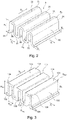
- Fig. 3 shows a blade 103 according to an embodiment of the present invention. This was formed by a manufacturing process comprising a bending forming step followed by a pressure forming step. The manufacturing process is related to Fig. 8 explained in more detail below.
- the blade 103 according to the invention Fig. 3 has a sharp-edged wavy structure with shaft roofs 131 and shaft webs 132, which follow each other alternately in the first spatial direction D1.
- the lower and upper shaft roofs 131 are flat and each extending parallel to each other, ie with a maximum deviation of 1 °, preferably 0.5 °.
- the shaft webs 132 are each arranged at right angles to the shaft roofs 131. Therefore, the wave webs 132, which extend in the second spatial direction D2, each extend parallel to each other, ie with a maximum deviation of 1 °, preferably 0.5 °.
- the wave roofs 131 are each connected via sharp-edged plate edges 134 with the shaft webs 132.
- the sheet edges 134 each have an outer radius R101 and an inner radius R102.
- the inner radii are in an aluminum alloy according to European standard EN-AW-3003 preferably 0.2 mm to 0.4 mm and the outer radii according to the invention 0.05 mm to 0.18 mm.
- the pitch is given as P101 and is usually 0.9mm to 5.0mm.
- the height H101 of the sipe 103 may be 4.0mm to 12mm.
- the wall thickness S101 can be in the range of 0.2mm to 1.0mm.
- the sharp edge contour of the sheet edges 134 with external radii R101 below 0.2 mm is achieved by a pressure forming step, in which the bending-converted lamella 3 off Fig.
- the wave roofs 131 thus have over their entire width (width in the first direction of space D1 running) apart from the outer radii R101 conditionally curved surface areas flat outer surfaces 135 for optimal connection by soldering also with flat, in FIGS. 9 and 10 shown dividing plates 4 on.
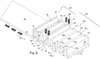
- Fig. 8 shows an embodiment of a manufacturing method for in Fig. 3 Lamella 103.
- Starting material for the production of the lamella 103 according to the invention is a flat, smooth metal sheet 20, for example made of an aluminum alloy according to European Standard EN-AW-3003 with a material thickness or wall thickness S1.
- the metal sheet 20 is preferably unwound from a Blechcoil, not shown.
- the flat metal sheet 20 is obtained by flat rolling a cast bar.
- the structure of the metal sheet 20 therefore has elongated grains 21, as in FIG Fig. 12 shown schematically.
- a first step (a) of the manufacturing method according to the invention the flat metal sheet 20 shown in the left figure section is bent by bending into a wave-shaped structure having one, two, or more shaft roofs 31 with respective adjacent shaft webs 32, as in FIG Fig. 2 represented and described above, brought.
- one or more tools preferably act in a rectilinear movement from below and / or above perpendicular to the sheet 20.
- Preferred is a Gleitziehbiegen.
- the drawn with arrows feed direction D1 of the sheet 20 during the Gleitziehbiegens coincides with the in Fig. 2 Plotted spatial direction D1.
- the bending forming can also be done by a rotating movement of the tool or by a combination of linear and rotating tool movement.
- the bending forming takes place according to a method described in DIN 8586.
- the structure ( Figure 12 ) of the bending-converted lamella 3 has, after the bending deformation according to step (a), elongate, rice-grain-shaped structure grains 21 as well as the metal sheet 20 which forms the starting material. In the area of the round bending edges 34 of the lamella 3, the structure grains may also have curvatures, which is not shown. If the bending forming also includes a Ziehumformanteil, so the grains 21 with respect to the existing structure in the sheet 20 on be stretched, ie have a greater length, but this is also not shown.
- the feed direction in the flat rolling of the sheet 20 is preferably consistent with the spatial direction D1 and thus with the feed direction D1 during bending forming according to step (a).
- a surface pressure is applied vertically to the outer surface 35 of one or more corrugated roofs 31 of the undulating structure, for example by means of a flat punch (illustrated by the arrows 50) from the outside.
- a flat punch illustrated by the arrows 50
- the metal material Due to the high compressive stress, the metal material is brought into a plastic state in which it begins to flow.
- the pressure forming takes place at ambient temperature, ie the metal is not heated from the outside before the pressure forming or during the pressure forming. It is therefore referred to as cold extrusion.
- metal is transferred from the curved shaft roof 31 and from the adjacent shaft webs 32 in the region of the bending edge 34 by flowing.
- the outer radius of the edge 34 is reduced from the original R1 to R101 and the blade is compressed or reduced in height from H1 to H101.
- the structure of the pressure-shaped blade 103 has spherical structure grains 121, as in Fig. 13 shown schematically on.
- the fin 103 thus produced has a surface with an average roughness Ra of less than 0.4 ⁇ m.
- the outer radius R101 (back to Fig. 8 ) is preferably below 0.18mm after the pressure forming step, more preferably below 0.15mm.
- the feed direction during pressure forming takes place as in the bending deformation in the spatial direction D1.
- the pressure forming of the wave-shaped structure is therefore mainly in the spatial direction D2.
- Result of the manufacturing method according to the invention Fig. 8 is the in Fig. 3 Lamella 103 already described above.
- the blade 103 according to the invention is for the production of a plate heat exchanger as above to Fig. 1 described used. Instead of in Fig. 1 slats provided with the reference numerals 2 and 3 become slats 103 according to FIG Fig. 3 used.
- solder-plated partitions 4 are alternately arranged with fins 103 and edge strips 8 with outer cover plates 5 in a stack above one another and soldered in a soldering oven. Subsequently, headers 7 are welded with nozzle 6 on the soldered heat exchanger block.
- Fig. 9 shows a cross section through a blade 103 according to the invention with adjacent brazed dividers.
- Fig. 10 shows a detail Y Fig. 9 .
- a respective solder layer 140 is formed with a constant thickness d, which covers the perpendicular to the separating plate 4 projected cross-section Q of the adjacent shaft web to 100%.
- a fillet weld 141 is formed at an outer radius R101 in the range of 0.05 mm to 0.18 mm outside the projected shaft cross-section Q, whereby the above-mentioned optimum solder layer cover geometry is achieved.
- Fig. 9 is the wall thickness of the pressure-shaped blade 103 in the region of the web 132 indicated by the reference numeral S2.
- the wall thickness S2 of the webs 132 is only slightly reduced in comparison to the wall thickness S1 (FIG. Fig. 8 ) of the flat sheet 20, which is the starting material.
- the percent wall thickness reduction is calculated as follows: ((S1-S2) / S1) * 100. This is less than 10%, more preferably less than 5%, and even more preferably less than 1%. This is not achievable with the conventional bending forming method for a lamella. In the prior art exclusively bend-formed laminations, the percent wall thickness reduction is typically at least 20%.
- a transversal wall thickness in the area of the pressure-formed sheet metal edge 134 is entered with the reference number S3.
- the percentage wall thickness increase is calculated as follows: ((S3-S1) / S1) * 100. This is preferably more than 1%, more preferably more than 5% and more preferably more than 10%. This is not achievable with the conventional bending forming method for a lamella.
- a reduction in the wall thickness of the lamella occurs in the region of a sheet metal edge bent exclusively by bending.
- Fig. 11 shows the soldering of an exclusively bending-converted blade 3 according to Fig. 2 and thus according to the prior art.
- the fillet weld 41 which forms during soldering between the outer edge R1 having bending edge 34 and the separating plate 4, in the region of the projected Wellenstegqueritess Q.
- the projected cross-section Q is formed no Lot für with a constant thickness.
- the fillet weld 41 does not bridge the entire projected cross-section Q of the shaft web 32: surface regions F of the wave webs 32 are not connected to the separating plates 4 via a closed solder layer. Such a solder joint has proved to be detrimental to the strength of the plate heat exchanger.
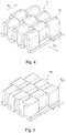
- Fig. 4 shows a bend-formed, cut lamella 3 after step (a) ( Fig. 8 ) of the method according to the invention and thus according to the prior art.
- This is made by Gleitziehbiegen a flat metal sheet with a superimposed simultaneously occurring cut by staggered individual dies. The offset is in the direction of D1 and alternates over the entire sheet width in direction D3.
- the cut length L is between 1.5 mm to 50 mm.
- a subsequent inventive pressure forming step (b) (according to Fig. 8 ), whose result in Fig. 5 is shown, the round wavy structure of Fig. 4 into a sharp-edged, wavy structure of Fig. 5 converted, in which the outer radius of the bending edge of R1 to R101 is preferably reduced to 0.05mm to 0.18mm.
- Fig. 6 shows a bending-transformed, perforated lamella 3 after step (a) ( Fig. 8 ) of the method according to the invention and thus according to the prior art.
- the perforations (holes 50) usually have distances between 2 mm and 30 mm and diameter in the range of 1 mm and 3 mm.
- a subsequent pressure forming step (b) accordinging to Fig. 8 ) whose result in Fig. 7 is shown is the round, wavy structure of Fig. 6 into a sharp-edged structure of Fig. 7 in which the outer radius of the bending edge is reduced from R1 to R101 to 0.05mm to 0.18mm.
- the blade 103 according to the Fig. 3 . 5 and 7 can be produced by the method according to the invention in a width (in direction D3) of for example 450 mm and a length (in direction D1) of 1500 mm.
Landscapes
- Engineering & Computer Science (AREA)
- Mechanical Engineering (AREA)
- Physics & Mathematics (AREA)
- Thermal Sciences (AREA)
- General Engineering & Computer Science (AREA)
- Heat-Exchange Devices With Radiators And Conduit Assemblies (AREA)
- Bending Of Plates, Rods, And Pipes (AREA)
- Shaping Metal By Deep-Drawing, Or The Like (AREA)
Applications Claiming Priority (3)
| Application Number | Priority Date | Filing Date | Title |
|---|---|---|---|
| EP15002883 | 2015-10-08 | ||
| EP16777909.9A EP3359902B2 (fr) | 2015-10-08 | 2016-10-06 | Procédé de fabrication d'une lamelle et un échangeur de chaleur à plaque avec une lamelle fabriquée à l'aide d'un tel procédé |
| PCT/EP2016/001661 WO2017059959A1 (fr) | 2015-10-08 | 2016-10-06 | Lamelle pour un échangeur de chaleur à plaques et procédé de fabrication associé |
Related Parent Applications (2)
| Application Number | Title | Priority Date | Filing Date |
|---|---|---|---|
| EP16777909.9A Division EP3359902B2 (fr) | 2015-10-08 | 2016-10-06 | Procédé de fabrication d'une lamelle et un échangeur de chaleur à plaque avec une lamelle fabriquée à l'aide d'un tel procédé |
| EP16777909.9A Division-Into EP3359902B2 (fr) | 2015-10-08 | 2016-10-06 | Procédé de fabrication d'une lamelle et un échangeur de chaleur à plaque avec une lamelle fabriquée à l'aide d'un tel procédé |
Publications (2)
| Publication Number | Publication Date |
|---|---|
| EP3531055A1 true EP3531055A1 (fr) | 2019-08-28 |
| EP3531055B1 EP3531055B1 (fr) | 2020-12-02 |
Family
ID=54291014
Family Applications (2)
| Application Number | Title | Priority Date | Filing Date |
|---|---|---|---|
| EP19020116.0A Active EP3531055B1 (fr) | 2015-10-08 | 2016-10-06 | Échangeur de chaleur à plaques et son procédé de fabrication |
| EP16777909.9A Active EP3359902B2 (fr) | 2015-10-08 | 2016-10-06 | Procédé de fabrication d'une lamelle et un échangeur de chaleur à plaque avec une lamelle fabriquée à l'aide d'un tel procédé |
Family Applications After (1)
| Application Number | Title | Priority Date | Filing Date |
|---|---|---|---|
| EP16777909.9A Active EP3359902B2 (fr) | 2015-10-08 | 2016-10-06 | Procédé de fabrication d'une lamelle et un échangeur de chaleur à plaque avec une lamelle fabriquée à l'aide d'un tel procédé |
Country Status (9)
| Country | Link |
|---|---|
| US (1) | US10578376B2 (fr) |
| EP (2) | EP3531055B1 (fr) |
| JP (1) | JP6851373B2 (fr) |
| CN (2) | CN113446879A (fr) |
| DK (1) | DK3359902T3 (fr) |
| ES (1) | ES2750899T3 (fr) |
| LT (1) | LT3359902T (fr) |
| RU (1) | RU2717184C2 (fr) |
| WO (1) | WO2017059959A1 (fr) |
Cited By (1)
| Publication number | Priority date | Publication date | Assignee | Title |
|---|---|---|---|---|
| WO2021069097A1 (fr) * | 2019-10-11 | 2021-04-15 | Linde Gmbh | Échangeur de chaleur à plaques, installation d'ingénierie des procédés et procédé associé |
Families Citing this family (17)
| Publication number | Priority date | Publication date | Assignee | Title |
|---|---|---|---|---|
| US11032944B2 (en) * | 2017-09-29 | 2021-06-08 | Intel Corporation | Crushable heat sink for electronic devices |
| US11454448B2 (en) | 2017-11-27 | 2022-09-27 | Dana Canada Corporation | Enhanced heat transfer surface |
| US11391523B2 (en) * | 2018-03-23 | 2022-07-19 | Raytheon Technologies Corporation | Asymmetric application of cooling features for a cast plate heat exchanger |
| US10458534B1 (en) * | 2018-05-31 | 2019-10-29 | Abb Schweiz Ag | Gearbox system with add-on cooling fin panels |
| MY202605A (en) * | 2018-09-25 | 2024-05-09 | Brentwood Ind Inc | Cross corrugated media and related method |
| US10845132B2 (en) * | 2018-11-05 | 2020-11-24 | Hamilton Sundstrand Corporation | Additively manufactured fin slots for thermal growth |
| US11466768B2 (en) | 2018-12-31 | 2022-10-11 | Abb Schweiz Ag | Methods and systems for cooling transmissions |
| US11287025B2 (en) | 2018-12-31 | 2022-03-29 | Abb Schweiz Ag | Cooling units for transmissions |
| US20200333077A1 (en) * | 2019-04-18 | 2020-10-22 | The Babcock & Wilcox Company | Perturbing air cooled condenser fin |
| WO2020245876A1 (fr) * | 2019-06-03 | 2020-12-10 | 三菱電機株式会社 | Échangeur de chaleur du type à plaques et dispositif de transfert de chaleur |
| FR3099563B1 (fr) | 2019-08-01 | 2021-07-30 | Air Liquide | Echangeur de chaleur avec configuration de passages et structures d’échange thermique améliorées |
| FR3099560B1 (fr) | 2019-08-01 | 2021-07-02 | Air Liquide | Procédé de liquéfaction de gaz naturel avec injection améliorée d’un courant réfrigérant mixte |
| FR3099557B1 (fr) * | 2019-08-01 | 2021-07-30 | Air Liquide | Procédé de liquéfaction de gaz naturel avec circulation améliorée d’un courant réfrigérant mixte |
| FR3099559B1 (fr) | 2019-08-01 | 2021-07-16 | Air Liquide | Procédé de liquéfaction de gaz naturel avec configuration d’échangeur améliorée |
| US11064632B2 (en) * | 2019-09-05 | 2021-07-13 | Ldc Precision Engineering Co., Ltd. | Heat-sinking improved structure for evaporators |
| US11174937B2 (en) | 2019-09-23 | 2021-11-16 | Abb Schweiz Ag | Speed reducer cooling fins and method of manufacturing |
| US20240208067A1 (en) * | 2022-12-27 | 2024-06-27 | Intrinsic Innovation Llc | Sensor-based adaptation for manipulation of deformable workpieces |
Citations (7)
| Publication number | Priority date | Publication date | Assignee | Title |
|---|---|---|---|---|
| DE10343107A1 (de) | 2002-10-01 | 2004-04-15 | Nordon Cryogenie Snc | Flügel für Plattenwärmetauscher, Verfahren zur Herstellung eines derartigen Flügels und Wärmetauscher mit einem derartigen Flügel |
| EP1630896A1 (fr) * | 2003-03-31 | 2006-03-01 | NEC Lamilion Energy, Ltd. | Element rayonnant pour accumulateur stratifie et son procede de fabrication |
| JP2007248014A (ja) * | 2006-03-17 | 2007-09-27 | Kobelco & Materials Copper Tube Inc | 熱交換器用扁平多孔管 |
| DE102009018247A1 (de) | 2009-04-21 | 2010-10-28 | Linde Aktiengesellschaft | Plattenwärmeaustauscher mit Profilen |
| EP2369284A2 (fr) * | 2010-03-23 | 2011-09-28 | AKG-Thermotechnik GmbH & Co.KG | Echangeur thermique, notamment pour sèche-linge à condensation |
| WO2012044288A1 (fr) * | 2010-09-29 | 2012-04-05 | Air Products And Chemicals, Inc. | Ailettes perforées pour échangeur de chaleur |
| EP2869013A1 (fr) * | 2013-11-05 | 2015-05-06 | Linde Aktiengesellschaft | Procédé d'échange de chaleur indirect entre des sels fondus et un échangeur de chaleur dans une centrale solaire thermique |
Family Cites Families (20)
| Publication number | Priority date | Publication date | Assignee | Title |
|---|---|---|---|---|
| JPS6020676B2 (ja) * | 1977-06-29 | 1985-05-23 | 株式会社日立製作所 | 熱交換器用粗面フィンの製作方法 |
| JP3644121B2 (ja) * | 1996-04-01 | 2005-04-27 | 株式会社デンソー | コルゲートフィンの成形装置および成形方法 |
| US5816320A (en) * | 1997-01-10 | 1998-10-06 | J.I.T. Engineering, Inc. | Radiator fin construction |
| FR2807828B1 (fr) * | 2000-04-17 | 2002-07-12 | Nordon Cryogenie Snc | Ailette ondulee a decalage partiel pour echangeur de chaleur a plaques et echangeur de chaleur a plaques correspondant |
| JP3602806B2 (ja) | 2001-03-29 | 2004-12-15 | 株式会社リョーサン | コルゲートフィン型ヒートシンクの製造方法 |
| FR2834783B1 (fr) | 2002-01-17 | 2004-06-11 | Air Liquide | Ailette d'echange thermique, son procede de fabrication et echangeur de chaleur correspondant |
| DE10235038A1 (de) * | 2002-07-31 | 2004-02-12 | Behr Gmbh & Co. | Flachrohr-Wärmeübertrager |
| FR2845152B1 (fr) | 2002-10-01 | 2005-06-17 | Air Liquide | Echangeur de chaleur a plaques comportant une ailette epaisse, et utilisation d'un tel echangeur de chaleur. |
| CN101061362B (zh) * | 2004-07-28 | 2011-11-09 | 瓦莱奥公司 | 具有内部翅片的汽车换热器装置及其制造方法 |
| US20070012430A1 (en) * | 2005-07-18 | 2007-01-18 | Duke Brian E | Heat exchangers with corrugated heat exchange elements of improved strength |
| JP2007232246A (ja) | 2006-02-28 | 2007-09-13 | Denso Corp | 熱交換器 |
| DE102006035209A1 (de) * | 2006-07-29 | 2008-01-31 | Modine Manufacturing Co., Racine | Wellrippe und Wärmetauscher |
| DE102007048474A1 (de) * | 2007-10-09 | 2009-04-16 | Behr Gmbh & Co. Kg | Verfahren zur Herstellung einer Turbulenzvorrichtung, Vorrichtung zur Durchführung des Verfahrens, Turbulenzvorrichtung |
| JP3140755U (ja) | 2008-01-21 | 2008-04-10 | 水谷電機工業株式会社 | コルゲートフィン型放熱器 |
| CN201199141Y (zh) * | 2008-02-03 | 2009-02-25 | 于凤梅 | 一种散热片 |
| CN101526324B (zh) | 2009-04-13 | 2010-07-28 | 三花丹佛斯(杭州)微通道换热器有限公司 | 翅片、具有该翅片的换热器和换热器装置 |
| US20110048688A1 (en) * | 2009-09-02 | 2011-03-03 | Delphi Technologies, Inc. | Heat Exchanger Assembly |
| CN201637329U (zh) * | 2010-02-03 | 2010-11-17 | 北京大起空调有限公司 | 空调冷凝器 |
| CN105063522B (zh) * | 2010-09-08 | 2018-09-28 | 奥科宁克公司 | 改进的6xxx铝合金及其生产方法 |
| US20120160451A1 (en) * | 2010-12-22 | 2012-06-28 | Flexenergy Energy Systems, Inc. | Refold heat exchanger |
-
2016
- 2016-10-06 ES ES16777909T patent/ES2750899T3/es active Active
- 2016-10-06 LT LT16777909T patent/LT3359902T/lt unknown
- 2016-10-06 WO PCT/EP2016/001661 patent/WO2017059959A1/fr not_active Ceased
- 2016-10-06 JP JP2018517796A patent/JP6851373B2/ja active Active
- 2016-10-06 EP EP19020116.0A patent/EP3531055B1/fr active Active
- 2016-10-06 DK DK16777909T patent/DK3359902T3/da active
- 2016-10-06 CN CN202110842376.7A patent/CN113446879A/zh active Pending
- 2016-10-06 EP EP16777909.9A patent/EP3359902B2/fr active Active
- 2016-10-06 CN CN201680058880.5A patent/CN108139179B/zh active Active
- 2016-10-06 RU RU2018109769A patent/RU2717184C2/ru active
- 2016-10-06 US US15/766,527 patent/US10578376B2/en active Active
Patent Citations (7)
| Publication number | Priority date | Publication date | Assignee | Title |
|---|---|---|---|---|
| DE10343107A1 (de) | 2002-10-01 | 2004-04-15 | Nordon Cryogenie Snc | Flügel für Plattenwärmetauscher, Verfahren zur Herstellung eines derartigen Flügels und Wärmetauscher mit einem derartigen Flügel |
| EP1630896A1 (fr) * | 2003-03-31 | 2006-03-01 | NEC Lamilion Energy, Ltd. | Element rayonnant pour accumulateur stratifie et son procede de fabrication |
| JP2007248014A (ja) * | 2006-03-17 | 2007-09-27 | Kobelco & Materials Copper Tube Inc | 熱交換器用扁平多孔管 |
| DE102009018247A1 (de) | 2009-04-21 | 2010-10-28 | Linde Aktiengesellschaft | Plattenwärmeaustauscher mit Profilen |
| EP2369284A2 (fr) * | 2010-03-23 | 2011-09-28 | AKG-Thermotechnik GmbH & Co.KG | Echangeur thermique, notamment pour sèche-linge à condensation |
| WO2012044288A1 (fr) * | 2010-09-29 | 2012-04-05 | Air Products And Chemicals, Inc. | Ailettes perforées pour échangeur de chaleur |
| EP2869013A1 (fr) * | 2013-11-05 | 2015-05-06 | Linde Aktiengesellschaft | Procédé d'échange de chaleur indirect entre des sels fondus et un échangeur de chaleur dans une centrale solaire thermique |
Non-Patent Citations (4)
| Title |
|---|
| "ALPEMA", 2010, article "The standards of the brazed aluminium plate-fin heat exchanger manufactures association", pages: 45 - 46 |
| "ALPEMA", 2010, article "The standards of the brazed aluminium plate-fin heat exchanger manufactures association", pages: 5 |
| "ALPEMA", 2010, article "The standards of the brazed aluminium plate-fin heat exchanger manufactures association", pages: 66 |
| "ALPEMA", 2010, article "The standards of the brazed aluminium plate-fin heat exchanger manufactures association", pages: 9,10 |
Cited By (1)
| Publication number | Priority date | Publication date | Assignee | Title |
|---|---|---|---|---|
| WO2021069097A1 (fr) * | 2019-10-11 | 2021-04-15 | Linde Gmbh | Échangeur de chaleur à plaques, installation d'ingénierie des procédés et procédé associé |
Also Published As
| Publication number | Publication date |
|---|---|
| ES2750899T3 (es) | 2020-03-27 |
| DK3359902T3 (da) | 2019-11-25 |
| CN113446879A (zh) | 2021-09-28 |
| CN108139179B (zh) | 2021-08-03 |
| WO2017059959A1 (fr) | 2017-04-13 |
| EP3359902A1 (fr) | 2018-08-15 |
| EP3531055B1 (fr) | 2020-12-02 |
| LT3359902T (lt) | 2019-11-11 |
| RU2018109769A3 (fr) | 2020-01-21 |
| JP6851373B2 (ja) | 2021-03-31 |
| RU2018109769A (ru) | 2019-11-08 |
| RU2717184C2 (ru) | 2020-03-18 |
| CN108139179A (zh) | 2018-06-08 |
| US20180299210A1 (en) | 2018-10-18 |
| JP2018529926A (ja) | 2018-10-11 |
| EP3359902B2 (fr) | 2023-06-28 |
| US10578376B2 (en) | 2020-03-03 |
| EP3359902B1 (fr) | 2019-09-04 |
Similar Documents
| Publication | Publication Date | Title |
|---|---|---|
| EP3359902B1 (fr) | Procédé de fabrication d'une lamelle et un échangeur de chaleur à plaque avec une lamelle fabriquée à l'aide d'un tel procédé | |
| DE3752324T2 (de) | Kondensator | |
| EP0519334B1 (fr) | Echangeur de chaleur à tubes plats, procédé pour sa fabrication, applications et tubes plats pour échangeur de chaleur | |
| DE60111469T2 (de) | Wärmetauscher und Verfahren zu dessen Herstellung | |
| EP2322297B1 (fr) | Tuyau plat doté d'un dépôt de turbulence pour un échangeur thermique, échangeur thermique doté de tels tuyaux plats, ainsi que procédé et dispositif de fabrication d'un tel tuyau plat | |
| DE102012204178B3 (de) | Mikrostrukturbauteil und Verfahren zu dessen Herstellung | |
| DE69503972T2 (de) | Verstärkte Endplatte für Wärmetauscher | |
| DE102009015849A1 (de) | Wärmetauscher | |
| DE4404837A1 (de) | Rippe für Wärmetauscher | |
| DE102012023800A1 (de) | Wärmetauscherrohr, Wärmetauscherrohranordnung und Verfahren zum Herstellen desselben | |
| EP2244045A2 (fr) | Échangeur thermique à plaques doté de profilés | |
| DE10054158A1 (de) | Mehrkammerrohr mit kreisförmigen Strömungskanälen | |
| DE10150213A1 (de) | Stranggepreßtes Profil, insbesondere für Wärmetauscher | |
| DE102012023990A1 (de) | Wärmetauscherrohr, Wärmetauscherrohranordnung und Verfahren zum Herstellen desselben | |
| EP2096397B1 (fr) | Ailette pour un échangeur thermique | |
| EP2049860B1 (fr) | Ailette ondulée et échangeur de chaleur | |
| DE102006002932B4 (de) | Wärmetauscher und Herstellungsverfahren für Wärmetauscher | |
| DE102007001430A1 (de) | Wärmetauscher | |
| EP0268831B1 (fr) | Lamelle | |
| DE202009017777U1 (de) | Konvektorbleche für Heizkörper | |
| EP2062002B1 (fr) | Noyau d' échangeur thermique, procédé de fabrication, ligne de profilage à galets | |
| DE102017112063A1 (de) | Lamelle, Verfahren und Vorrichtung zur Herstellung einer Lamelle und Wärmeaustauscher | |
| DE102012023801A1 (de) | Wärmetauscherrohr, Wärmetauscherrohranordnung und Verfahren zum Herstellen desselben | |
| DE19846347C2 (de) | Wärmeaustauscher aus Aluminium oder einer Aluminium-Legierung | |
| DE102005048407A1 (de) | Aus einem profilierten gerollten Metallprodukt hergestellte Röhre und Verfahren zur Herstellung derselben |
Legal Events
| Date | Code | Title | Description |
|---|---|---|---|
| PUAI | Public reference made under article 153(3) epc to a published international application that has entered the european phase |
Free format text: ORIGINAL CODE: 0009012 |
|
| STAA | Information on the status of an ep patent application or granted ep patent |
Free format text: STATUS: THE APPLICATION HAS BEEN PUBLISHED |
|
| AC | Divisional application: reference to earlier application |
Ref document number: 3359902 Country of ref document: EP Kind code of ref document: P |
|
| AK | Designated contracting states |
Kind code of ref document: A1 Designated state(s): AL AT BE BG CH CY CZ DE DK EE ES FI FR GB GR HR HU IE IS IT LI LT LU LV MC MK MT NL NO PL PT RO RS SE SI SK SM TR |
|
| STAA | Information on the status of an ep patent application or granted ep patent |
Free format text: STATUS: REQUEST FOR EXAMINATION WAS MADE |
|
| 17P | Request for examination filed |
Effective date: 20200226 |
|
| RBV | Designated contracting states (corrected) |
Designated state(s): AL AT BE BG CH CY CZ DE DK EE ES FI FR GB GR HR HU IE IS IT LI LT LU LV MC MK MT NL NO PL PT RO RS SE SI SK SM TR |
|
| GRAP | Despatch of communication of intention to grant a patent |
Free format text: ORIGINAL CODE: EPIDOSNIGR1 |
|
| STAA | Information on the status of an ep patent application or granted ep patent |
Free format text: STATUS: GRANT OF PATENT IS INTENDED |
|
| INTG | Intention to grant announced |
Effective date: 20200417 |
|
| RAP1 | Party data changed (applicant data changed or rights of an application transferred) |
Owner name: LINDE GMBH |
|
| GRAJ | Information related to disapproval of communication of intention to grant by the applicant or resumption of examination proceedings by the epo deleted |
Free format text: ORIGINAL CODE: EPIDOSDIGR1 |
|
| STAA | Information on the status of an ep patent application or granted ep patent |
Free format text: STATUS: REQUEST FOR EXAMINATION WAS MADE |
|
| INTC | Intention to grant announced (deleted) | ||
| GRAR | Information related to intention to grant a patent recorded |
Free format text: ORIGINAL CODE: EPIDOSNIGR71 |
|
| GRAS | Grant fee paid |
Free format text: ORIGINAL CODE: EPIDOSNIGR3 |
|
| STAA | Information on the status of an ep patent application or granted ep patent |
Free format text: STATUS: GRANT OF PATENT IS INTENDED |
|
| GRAA | (expected) grant |
Free format text: ORIGINAL CODE: 0009210 |
|
| STAA | Information on the status of an ep patent application or granted ep patent |
Free format text: STATUS: THE PATENT HAS BEEN GRANTED |
|
| INTG | Intention to grant announced |
Effective date: 20201006 |
|
| AC | Divisional application: reference to earlier application |
Ref document number: 3359902 Country of ref document: EP Kind code of ref document: P |
|
| AK | Designated contracting states |
Kind code of ref document: B1 Designated state(s): AL AT BE BG CH CY CZ DE DK EE ES FI FR GB GR HR HU IE IS IT LI LT LU LV MC MK MT NL NO PL PT RO RS SE SI SK SM TR |
|
| REG | Reference to a national code |
Ref country code: GB Ref legal event code: FG4D Free format text: NOT ENGLISH |
|
| REG | Reference to a national code |
Ref country code: AT Ref legal event code: REF Ref document number: 1341403 Country of ref document: AT Kind code of ref document: T Effective date: 20201215 Ref country code: CH Ref legal event code: EP |
|
| REG | Reference to a national code |
Ref country code: IE Ref legal event code: FG4D Free format text: LANGUAGE OF EP DOCUMENT: GERMAN |
|
| REG | Reference to a national code |
Ref country code: DE Ref legal event code: R096 Ref document number: 502016011883 Country of ref document: DE |
|
| REG | Reference to a national code |
Ref country code: NL Ref legal event code: FP |
|
| REG | Reference to a national code |
Ref country code: SE Ref legal event code: TRGR |
|
| REG | Reference to a national code |
Ref country code: NO Ref legal event code: T2 Effective date: 20201202 |
|
| PG25 | Lapsed in a contracting state [announced via postgrant information from national office to epo] |
Ref country code: FI Free format text: LAPSE BECAUSE OF FAILURE TO SUBMIT A TRANSLATION OF THE DESCRIPTION OR TO PAY THE FEE WITHIN THE PRESCRIBED TIME-LIMIT Effective date: 20201202 Ref country code: RS Free format text: LAPSE BECAUSE OF FAILURE TO SUBMIT A TRANSLATION OF THE DESCRIPTION OR TO PAY THE FEE WITHIN THE PRESCRIBED TIME-LIMIT Effective date: 20201202 Ref country code: GR Free format text: LAPSE BECAUSE OF FAILURE TO SUBMIT A TRANSLATION OF THE DESCRIPTION OR TO PAY THE FEE WITHIN THE PRESCRIBED TIME-LIMIT Effective date: 20210303 |
|
| PG25 | Lapsed in a contracting state [announced via postgrant information from national office to epo] |
Ref country code: BG Free format text: LAPSE BECAUSE OF FAILURE TO SUBMIT A TRANSLATION OF THE DESCRIPTION OR TO PAY THE FEE WITHIN THE PRESCRIBED TIME-LIMIT Effective date: 20210302 Ref country code: LV Free format text: LAPSE BECAUSE OF FAILURE TO SUBMIT A TRANSLATION OF THE DESCRIPTION OR TO PAY THE FEE WITHIN THE PRESCRIBED TIME-LIMIT Effective date: 20201202 Ref country code: PL Free format text: LAPSE BECAUSE OF FAILURE TO SUBMIT A TRANSLATION OF THE DESCRIPTION OR TO PAY THE FEE WITHIN THE PRESCRIBED TIME-LIMIT Effective date: 20201202 |
|
| PG25 | Lapsed in a contracting state [announced via postgrant information from national office to epo] |
Ref country code: HR Free format text: LAPSE BECAUSE OF FAILURE TO SUBMIT A TRANSLATION OF THE DESCRIPTION OR TO PAY THE FEE WITHIN THE PRESCRIBED TIME-LIMIT Effective date: 20201202 |
|
| REG | Reference to a national code |
Ref country code: LT Ref legal event code: MG9D |
|
| PG25 | Lapsed in a contracting state [announced via postgrant information from national office to epo] |
Ref country code: RO Free format text: LAPSE BECAUSE OF FAILURE TO SUBMIT A TRANSLATION OF THE DESCRIPTION OR TO PAY THE FEE WITHIN THE PRESCRIBED TIME-LIMIT Effective date: 20201202 Ref country code: PT Free format text: LAPSE BECAUSE OF FAILURE TO SUBMIT A TRANSLATION OF THE DESCRIPTION OR TO PAY THE FEE WITHIN THE PRESCRIBED TIME-LIMIT Effective date: 20210405 Ref country code: LT Free format text: LAPSE BECAUSE OF FAILURE TO SUBMIT A TRANSLATION OF THE DESCRIPTION OR TO PAY THE FEE WITHIN THE PRESCRIBED TIME-LIMIT Effective date: 20201202 Ref country code: SK Free format text: LAPSE BECAUSE OF FAILURE TO SUBMIT A TRANSLATION OF THE DESCRIPTION OR TO PAY THE FEE WITHIN THE PRESCRIBED TIME-LIMIT Effective date: 20201202 Ref country code: SM Free format text: LAPSE BECAUSE OF FAILURE TO SUBMIT A TRANSLATION OF THE DESCRIPTION OR TO PAY THE FEE WITHIN THE PRESCRIBED TIME-LIMIT Effective date: 20201202 Ref country code: CZ Free format text: LAPSE BECAUSE OF FAILURE TO SUBMIT A TRANSLATION OF THE DESCRIPTION OR TO PAY THE FEE WITHIN THE PRESCRIBED TIME-LIMIT Effective date: 20201202 Ref country code: EE Free format text: LAPSE BECAUSE OF FAILURE TO SUBMIT A TRANSLATION OF THE DESCRIPTION OR TO PAY THE FEE WITHIN THE PRESCRIBED TIME-LIMIT Effective date: 20201202 |
|
| REG | Reference to a national code |
Ref country code: DE Ref legal event code: R097 Ref document number: 502016011883 Country of ref document: DE |
|
| PG25 | Lapsed in a contracting state [announced via postgrant information from national office to epo] |
Ref country code: IS Free format text: LAPSE BECAUSE OF FAILURE TO SUBMIT A TRANSLATION OF THE DESCRIPTION OR TO PAY THE FEE WITHIN THE PRESCRIBED TIME-LIMIT Effective date: 20210402 |
|
| PLBE | No opposition filed within time limit |
Free format text: ORIGINAL CODE: 0009261 |
|
| STAA | Information on the status of an ep patent application or granted ep patent |
Free format text: STATUS: NO OPPOSITION FILED WITHIN TIME LIMIT |
|
| PG25 | Lapsed in a contracting state [announced via postgrant information from national office to epo] |
Ref country code: IT Free format text: LAPSE BECAUSE OF FAILURE TO SUBMIT A TRANSLATION OF THE DESCRIPTION OR TO PAY THE FEE WITHIN THE PRESCRIBED TIME-LIMIT Effective date: 20201202 Ref country code: AL Free format text: LAPSE BECAUSE OF FAILURE TO SUBMIT A TRANSLATION OF THE DESCRIPTION OR TO PAY THE FEE WITHIN THE PRESCRIBED TIME-LIMIT Effective date: 20201202 |
|
| 26N | No opposition filed |
Effective date: 20210903 |
|
| PG25 | Lapsed in a contracting state [announced via postgrant information from national office to epo] |
Ref country code: DK Free format text: LAPSE BECAUSE OF FAILURE TO SUBMIT A TRANSLATION OF THE DESCRIPTION OR TO PAY THE FEE WITHIN THE PRESCRIBED TIME-LIMIT Effective date: 20201202 Ref country code: SI Free format text: LAPSE BECAUSE OF FAILURE TO SUBMIT A TRANSLATION OF THE DESCRIPTION OR TO PAY THE FEE WITHIN THE PRESCRIBED TIME-LIMIT Effective date: 20201202 |
|
| PG25 | Lapsed in a contracting state [announced via postgrant information from national office to epo] |
Ref country code: ES Free format text: LAPSE BECAUSE OF FAILURE TO SUBMIT A TRANSLATION OF THE DESCRIPTION OR TO PAY THE FEE WITHIN THE PRESCRIBED TIME-LIMIT Effective date: 20201202 |
|
| REG | Reference to a national code |
Ref country code: CH Ref legal event code: PL |
|
| PG25 | Lapsed in a contracting state [announced via postgrant information from national office to epo] |
Ref country code: IS Free format text: LAPSE BECAUSE OF FAILURE TO SUBMIT A TRANSLATION OF THE DESCRIPTION OR TO PAY THE FEE WITHIN THE PRESCRIBED TIME-LIMIT Effective date: 20210402 |
|
| REG | Reference to a national code |
Ref country code: BE Ref legal event code: MM Effective date: 20211031 |
|
| GBPC | Gb: european patent ceased through non-payment of renewal fee |
Effective date: 20211006 |
|
| PG25 | Lapsed in a contracting state [announced via postgrant information from national office to epo] |
Ref country code: MC Free format text: LAPSE BECAUSE OF FAILURE TO SUBMIT A TRANSLATION OF THE DESCRIPTION OR TO PAY THE FEE WITHIN THE PRESCRIBED TIME-LIMIT Effective date: 20201202 |
|
| PG25 | Lapsed in a contracting state [announced via postgrant information from national office to epo] |
Ref country code: LU Free format text: LAPSE BECAUSE OF NON-PAYMENT OF DUE FEES Effective date: 20211006 Ref country code: GB Free format text: LAPSE BECAUSE OF NON-PAYMENT OF DUE FEES Effective date: 20211006 Ref country code: BE Free format text: LAPSE BECAUSE OF NON-PAYMENT OF DUE FEES Effective date: 20211031 |
|
| PG25 | Lapsed in a contracting state [announced via postgrant information from national office to epo] |
Ref country code: LI Free format text: LAPSE BECAUSE OF NON-PAYMENT OF DUE FEES Effective date: 20211031 Ref country code: CH Free format text: LAPSE BECAUSE OF NON-PAYMENT OF DUE FEES Effective date: 20211031 |
|
| PG25 | Lapsed in a contracting state [announced via postgrant information from national office to epo] |
Ref country code: IE Free format text: LAPSE BECAUSE OF NON-PAYMENT OF DUE FEES Effective date: 20211006 |
|
| REG | Reference to a national code |
Ref country code: AT Ref legal event code: MM01 Ref document number: 1341403 Country of ref document: AT Kind code of ref document: T Effective date: 20211006 |
|
| PG25 | Lapsed in a contracting state [announced via postgrant information from national office to epo] |
Ref country code: AT Free format text: LAPSE BECAUSE OF NON-PAYMENT OF DUE FEES Effective date: 20211006 |
|
| PG25 | Lapsed in a contracting state [announced via postgrant information from national office to epo] |
Ref country code: CY Free format text: LAPSE BECAUSE OF FAILURE TO SUBMIT A TRANSLATION OF THE DESCRIPTION OR TO PAY THE FEE WITHIN THE PRESCRIBED TIME-LIMIT Effective date: 20201202 |
|
| P01 | Opt-out of the competence of the unified patent court (upc) registered |
Effective date: 20230525 |
|
| PG25 | Lapsed in a contracting state [announced via postgrant information from national office to epo] |
Ref country code: HU Free format text: LAPSE BECAUSE OF FAILURE TO SUBMIT A TRANSLATION OF THE DESCRIPTION OR TO PAY THE FEE WITHIN THE PRESCRIBED TIME-LIMIT; INVALID AB INITIO Effective date: 20161006 |
|
| PG25 | Lapsed in a contracting state [announced via postgrant information from national office to epo] |
Ref country code: MK Free format text: LAPSE BECAUSE OF FAILURE TO SUBMIT A TRANSLATION OF THE DESCRIPTION OR TO PAY THE FEE WITHIN THE PRESCRIBED TIME-LIMIT Effective date: 20201202 |
|
| PG25 | Lapsed in a contracting state [announced via postgrant information from national office to epo] |
Ref country code: MT Free format text: LAPSE BECAUSE OF FAILURE TO SUBMIT A TRANSLATION OF THE DESCRIPTION OR TO PAY THE FEE WITHIN THE PRESCRIBED TIME-LIMIT Effective date: 20201202 |
|
| PGFP | Annual fee paid to national office [announced via postgrant information from national office to epo] |
Ref country code: TR Payment date: 20250929 Year of fee payment: 10 |
|
| PGFP | Annual fee paid to national office [announced via postgrant information from national office to epo] |
Ref country code: NL Payment date: 20251023 Year of fee payment: 10 |
|
| PGFP | Annual fee paid to national office [announced via postgrant information from national office to epo] |
Ref country code: DE Payment date: 20251020 Year of fee payment: 10 |
|
| PGFP | Annual fee paid to national office [announced via postgrant information from national office to epo] |
Ref country code: NO Payment date: 20251022 Year of fee payment: 10 |
|
| PGFP | Annual fee paid to national office [announced via postgrant information from national office to epo] |
Ref country code: FR Payment date: 20251029 Year of fee payment: 10 |
|
| PGFP | Annual fee paid to national office [announced via postgrant information from national office to epo] |
Ref country code: SE Payment date: 20251023 Year of fee payment: 10 |