EP3531067B1 - Dispositif et procédé de mesure d'au moins un objet optiquement actif - Google Patents
Dispositif et procédé de mesure d'au moins un objet optiquement actif Download PDFInfo
- Publication number
- EP3531067B1 EP3531067B1 EP19000092.7A EP19000092A EP3531067B1 EP 3531067 B1 EP3531067 B1 EP 3531067B1 EP 19000092 A EP19000092 A EP 19000092A EP 3531067 B1 EP3531067 B1 EP 3531067B1
- Authority
- EP
- European Patent Office
- Prior art keywords
- radiation
- optically active
- active object
- lens
- measuring
- Prior art date
- Legal status (The legal status is an assumption and is not a legal conclusion. Google has not performed a legal analysis and makes no representation as to the accuracy of the status listed.)
- Active
Links
Images

Classifications
-
- G—PHYSICS
- G01—MEASURING; TESTING
- G01B—MEASURING LENGTH, THICKNESS OR SIMILAR LINEAR DIMENSIONS; MEASURING ANGLES; MEASURING AREAS; MEASURING IRREGULARITIES OF SURFACES OR CONTOURS
- G01B11/00—Measuring arrangements characterised by the use of optical techniques
- G01B11/24—Measuring arrangements characterised by the use of optical techniques for measuring contours or curvatures
- G01B11/25—Measuring arrangements characterised by the use of optical techniques for measuring contours or curvatures by projecting a pattern, e.g. one or more lines, moiré fringes on the object
- G01B11/2513—Measuring arrangements characterised by the use of optical techniques for measuring contours or curvatures by projecting a pattern, e.g. one or more lines, moiré fringes on the object with several lines being projected in more than one direction, e.g. grids, patterns
-
- G—PHYSICS
- G01—MEASURING; TESTING
- G01B—MEASURING LENGTH, THICKNESS OR SIMILAR LINEAR DIMENSIONS; MEASURING ANGLES; MEASURING AREAS; MEASURING IRREGULARITIES OF SURFACES OR CONTOURS
- G01B11/00—Measuring arrangements characterised by the use of optical techniques
- G01B11/24—Measuring arrangements characterised by the use of optical techniques for measuring contours or curvatures
- G01B11/255—Measuring arrangements characterised by the use of optical techniques for measuring contours or curvatures for measuring radius of curvature
-
- G—PHYSICS
- G01—MEASURING; TESTING
- G01M—TESTING STATIC OR DYNAMIC BALANCE OF MACHINES OR STRUCTURES; TESTING OF STRUCTURES OR APPARATUS, NOT OTHERWISE PROVIDED FOR
- G01M11/00—Testing of optical apparatus; Testing structures by optical methods not otherwise provided for
- G01M11/02—Testing optical properties
- G01M11/0207—Details of measuring devices
-
- G—PHYSICS
- G01—MEASURING; TESTING
- G01M—TESTING STATIC OR DYNAMIC BALANCE OF MACHINES OR STRUCTURES; TESTING OF STRUCTURES OR APPARATUS, NOT OTHERWISE PROVIDED FOR
- G01M11/00—Testing of optical apparatus; Testing structures by optical methods not otherwise provided for
- G01M11/02—Testing optical properties
- G01M11/0228—Testing optical properties by measuring refractive power
-
- G—PHYSICS
- G01—MEASURING; TESTING
- G01M—TESTING STATIC OR DYNAMIC BALANCE OF MACHINES OR STRUCTURES; TESTING OF STRUCTURES OR APPARATUS, NOT OTHERWISE PROVIDED FOR
- G01M11/00—Testing of optical apparatus; Testing structures by optical methods not otherwise provided for
- G01M11/02—Testing optical properties
- G01M11/0228—Testing optical properties by measuring refractive power
- G01M11/0235—Testing optical properties by measuring refractive power by measuring multiple properties of lenses, automatic lens meters
-
- G—PHYSICS
- G01—MEASURING; TESTING
- G01M—TESTING STATIC OR DYNAMIC BALANCE OF MACHINES OR STRUCTURES; TESTING OF STRUCTURES OR APPARATUS, NOT OTHERWISE PROVIDED FOR
- G01M11/00—Testing of optical apparatus; Testing structures by optical methods not otherwise provided for
- G01M11/02—Testing optical properties
- G01M11/0242—Testing optical properties by measuring geometrical properties or aberrations
- G01M11/025—Testing optical properties by measuring geometrical properties or aberrations by determining the shape of the object to be tested
-
- G—PHYSICS
- G01—MEASURING; TESTING
- G01M—TESTING STATIC OR DYNAMIC BALANCE OF MACHINES OR STRUCTURES; TESTING OF STRUCTURES OR APPARATUS, NOT OTHERWISE PROVIDED FOR
- G01M11/00—Testing of optical apparatus; Testing structures by optical methods not otherwise provided for
- G01M11/02—Testing optical properties
- G01M11/0242—Testing optical properties by measuring geometrical properties or aberrations
- G01M11/0257—Testing optical properties by measuring geometrical properties or aberrations by analyzing the image formed by the object to be tested
-
- G—PHYSICS
- G01—MEASURING; TESTING
- G01M—TESTING STATIC OR DYNAMIC BALANCE OF MACHINES OR STRUCTURES; TESTING OF STRUCTURES OR APPARATUS, NOT OTHERWISE PROVIDED FOR
- G01M11/00—Testing of optical apparatus; Testing structures by optical methods not otherwise provided for
- G01M11/02—Testing optical properties
- G01M11/0242—Testing optical properties by measuring geometrical properties or aberrations
- G01M11/0278—Detecting defects of the object to be tested, e.g. scratches or dust
-
- G—PHYSICS
- G01—MEASURING; TESTING
- G01M—TESTING STATIC OR DYNAMIC BALANCE OF MACHINES OR STRUCTURES; TESTING OF STRUCTURES OR APPARATUS, NOT OTHERWISE PROVIDED FOR
- G01M11/00—Testing of optical apparatus; Testing structures by optical methods not otherwise provided for
- G01M11/02—Testing optical properties
- G01M11/0285—Testing optical properties by measuring material or chromatic transmission properties
Definitions
- the present invention relates to a method for measuring at least one optically active object having a top side and a bottom side, wherein the at least one optically active object is irradiated with measuring radiation and the resulting radiation is measured.
- the present invention further relates to a device for measuring at least one optically active object, comprising a radiation source, a measuring device, and means for holding the at least one optically active object between the radiation source and the measuring device.
- a generic device and a generic method are known from the international patent application WO 2016/095939 A1
- This document describes a method and a device for edge processing of an optical lens, wherein the device comprises a measuring device for determining the orientation and contour of the optical lens.
- the optical lens is arranged between a radiation source and a measuring device.
- a disadvantage of this method is that only the data required for edge processing of the optical lens can be determined.
- the international patent application WO 2014/019806 discloses a method and a device for determining a geometric property of a lens for a spectacle lens using the fluorescence effect.
- a surface of the lens to be measured is irradiated vertically with strip-shaped excitation radiation, with the lens being passed under the excitation radiation.
- the generated fluorescence radiation is detected by a camera arranged at an angle.
- the evaluation is performed by comparing the detected image with reference values for given lens types (e.g., single vision, bifocal, progressive, etc.).
- This measuring device and the method that can be performed with it are limited to the contactless scanning of the lens surface and the rapid determination of the lens type.
- German patent application DE 198 37 932 A1 describes a method and a device for determining the surface shape of the cornea of the human eye using the fluorescence effect, whereby the surface is measured by triangulation.
- the cornea is irradiated with excitation radiation, while at the same time a striped pattern is projected onto the cornea, and the The resulting striped fluorescence radiation is detected and evaluated.
- This device and method are designed for the requirements and conditions of laser corneal surgery.
- the international patent application WO 2005/121740 A1 discloses a measuring device for lenses for detecting various types of defects in the lens surface.
- a programmable LCD screen produces periodically repeating grid patterns.
- the lens to be measured is captured with multiple images using temporally and spatially shifted grid patterns.
- the individual images are computer-generated into an overall image that visualizes surface defects in the lens.
- This measuring device is also limited to the acquisition of specific data, namely surface defects in the lens.
- US 2011/0075887 A1 relates to a device and a method for determining the shift of a lens focus.
- a first radiation source emits light, which is deflected by a semi-transparent mirror onto a lens, reflected by the lens, and captured by a camera. The position of the lens in a frame is determined using the reflected radiation.
- the device has a second light source, the radiation from which is transmitted through the lens and captured by the same camera. The radiation from the second light source is used to determine the lens focus.
- a shift in the lens focus can be determined using the position of the lens and the lens focus.
- the EP 1 093 907 A2 relates to a method and a device for automatically blocking a lens, wherein geometric and/or optical properties of the lens are determined before blocking.
- the device can have a light source. The light is directed onto the lens via a semi-transparent mirror, passes through the lens and is then reflected by a screen, passes through the lens again and is then captured by a camera.
- the device can have a further light source which generates a beam grid which is transmitted through the lens and captured by a camera. If both light sources are provided, the screen can be pivoted so that either the light source can be used to determine the geometric properties or the light source can be used to determine the optical properties.
- the object of the present invention is therefore to further develop a generic device such that a compact device is provided for determining various parameters, in particular optical properties of the optically active object. Accordingly, a generic method is to be further developed such that various parameters of the optically active object can be determined.
- the solution consists in a method having the features of patent claim 1 and in a device having the features of patent claim 8.
- the method according to the invention is characterized in that at least one excitation radiation for exciting luminescence radiation in the material of the optically active object and/or in the material of a coating of the optically active object is used as measuring radiation and the luminescence radiation is measured and/or detected as the resulting radiation and at least one measuring radiation passing through the optically active object is used and the transmission radiation is measured and/or detected as the resulting radiation.
- the resulting luminescence radiation is used to triangulate the surface(s) of the irradiated top side and/or the irradiated bottom side of the optically effective object.
- the triangulation results in numerous measurement points distributed across the irradiated top or bottom side, allowing for particularly precise evaluation to determine parameters of the top or bottom side.
- the method according to the invention enables the use of the resulting transmission radiation to determine the refractive power of the optically active object and/or characteristics of the optically active object.
- the method according to the invention thus allows the successive or preferably simultaneous determination of a wide variety of parameters of the optically effective object, in particular the areal evaluation of the refractive power of the optically effective object.
- radiation reflectable from the optically effective object can be used and the resulting reflected radiation can be measured and/or detected.
- the device according to the invention is characterized in that it has at least a first radiation source and at least a second radiation source, that it has at least one measuring and/or detection device and at least one evaluation device, wherein the at least first radiation source is oriented towards a top side or a bottom side of the optically active object and the at least second radiation source is oriented towards a top side of the optically active object, wherein the at least first radiation source emits excitation radiation for exciting luminescence radiation in the material of the optically active object and/or in the material of a coating of the optically active object, wherein the at least second radiation source emits radiation that passes through the optically active object at least, and wherein the device is designed to carry out the method according to the invention.
- the device according to the invention and the method according to the invention thus allow the optically effective object to be measured in a particularly simple and flexible manner, in particular depending on the measurement data desired in the individual case, depending on the properties of the material or materials of the optically effective object to be measured and its processing status.
- Both the device according to the invention and the method according to the invention can be easily integrated into an existing processing system for the optically effective object to be measured, both with regard to existing processing devices and with regard to existing processing sequences.
- the device according to the invention is further characterized by a simple design.
- it is not absolutely necessary to provide telecentric devices because the design of the device according to the invention allows for calibration measurements.
- the design of the device according to the invention can be easily adapted to the requirements of the individual case, which may arise, for example, from the material properties of the optically active object to be measured.
- the wavelength of the excitation radiation for the luminescence radiation can be adapted, if necessary, to the luminescence properties of the material of the optically active object and/or its coating in the individual case, for example, by means of switchable filters or by simply exchanging the radiation source.
- Excitation radiation with a wavelength in the range of approximately 200 nm (UV radiation) to approximately 575 nm (radiation in the visible range; green) is particularly preferred, since the wavelengths of the emitted luminescence radiation are then generally still in the visible wavelength range (up to approximately 750 nm; red) and are therefore particularly easy to measure and/or detect.
- optically active objects made of materials with different luminescence properties, particularly with excitation radiation of different wavelengths, to be easily measured by adapting the wavelength of the excitation radiation through a suitable selection of the respective radiation source.
- the wavelength of the excitation radiation emitted by the respective radiation source is therefore selected so that the desired luminescence effect occurs depending on the selected material of the optically active object.
- a further advantage is that either the material of the optically active object itself or the material of any coating present on the optically active object can be excited to excite luminescence radiation.
- the simple design of the device according to the invention also allows the device to be arranged as such, for example, on a frame, a holder, or a workbench, and used to carry out the method according to the invention.
- the device according to the invention can also be integrated into another device, for example, for processing, in particular shaping, an optically effective object.
- a further preferred embodiment of the device according to the invention consists in using one or more lasers as at least the first radiation source.
- the radiation emitted by a laser is generally comparatively high-energy, resulting in a correspondingly high signal strength detected by the measuring and/or detection device.
- the method according to the invention further enables the linking of measurement data from two or more measurement methods performed successively or simultaneously using the device according to the invention.
- This makes it possible, for example, to determine a planar evaluation of the refractive power of the optically effective object (so-called "power map").
- power map a planar evaluation of the refractive power of the optically effective object
- prisms incorporated into an optically effective object in the form of an optical lens from prism aberrations. This applies both to prism aberrations that can arise during the shaping of a lens and to prism aberrations that can be detected due to incorrect positioning of a lens during its measurement.
- the device according to the invention and the method according to the invention make it possible to remove optically effective objects containing processing or other defects from a processing device or a processing process as soon as possible after the defect occurs.
- the at least first radiation source emits at least one excitation radiation for exciting fluorescent radiation in the material of the optically active object and/or in the material of a coating of the optically active object. This avoids prolonged afterglow of the material(s), which could interfere with the subsequent processing method and/or the subsequent processing sequence.
- the at least first radiation source excites point-shaped, line-shaped, grid-shaped and/or raster-shaped luminescence radiation.
- This can be done, for example, by inserting a slit or mask of any design into the beam path of the excitation radiation emitted by the at least first radiation source, so that the light emitted from the slit or mask Emerging excitation radiation strikes the optically active object to be measured in the form of a corresponding pattern and excites luminescence radiation in the form of this pattern.
- an arrangement or array of two or more radiation sources each emitting, for example, point-shaped or line-shaped excitation beams that strike the optically active object to be measured in such a way that a defined pattern results, for example, a point pattern, line pattern, stripe pattern, grid pattern, checkered pattern, and so on.
- the at least second radiation source emits at least one radiation in the form of pixels and/or patterns. This is particularly advantageous for measuring and/or detecting parameters of the optically active object, such as its contour, its edge, its diameter, the position of markings (engravings, etc.) incorporated into the object, or the position of multifocal areas in bifocal or trifocal lenses.
- the at least one measuring and/or detection device and at least one of the radiation sources are oriented toward the same top or bottom side of the optically active object (60).
- the at least one radiation source can be used both to emit reflectable radiation and to emit excitation radiation to excite a luminescence effect.
- the device and method according to the invention can be used in particular for measuring ophthalmic lenses and lens blanks at any processing stage or at any position in a processing system.
- any other optically active objects can also be measured, e.g., optical lenses for microscopes, camera lenses, binoculars, or telescopes.
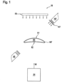
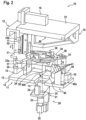
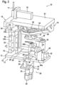
- the Figures 1 to 3 show an embodiment of the device 10 according to the invention.
- the exemplary embodiment serves to measure an optically active object 60 in the form of an optical lens (hereinafter: lens 60) with a convex upper side 61 in the exemplary embodiment and a concave lower side 62 in the exemplary embodiment.
- the lens 60 can further be provided in a manner known per se with a coating 60', for example an anti-reflective and/or a hard coating (hardcoat).
- the device 10 has at least a first radiation source 40, optionally a further radiation source 40' with an upstream slit diaphragm or mask 43' for generating a radiation pattern, a second radiation source 50, and a measuring and/or detection device 20.
- the orientation of a measuring and/or detection unit for example the camera lens 23 of a camera 22 of the measuring and/or detection device (see below), defines a measuring axis M.
- the device 10 can be arranged in a conventional manner on a frame, a holder, or a work table. However, the device can also be integrated, for example, into a device for processing, for example, for shaping, an optically effective object, for example, an optical lens, in particular an ophthalmic lens.
- a device for processing for example, for shaping, an optically effective object, for example, an optical lens, in particular an ophthalmic lens.
- an embodiment of a device 10 according to the invention has a holding table 11 with a bottom side 12 and a top side 13.
- a camera unit 20 is attached to the underside 12 of the support table 11.
- the camera unit 20 has a mount 21 on which a camera 22 (in the exemplary embodiment, a camera with a CCD sensor) with a camera lens 23 is mounted.
- the camera lens 23 is directed vertically upward.
- the camera 22 is provided with a polarizing filter (not shown). Therefore, a motor 24, in the exemplary embodiment an electrically operated stepper motor, is arranged above the camera lens 23 on the mount 21 for rotating the polarizing filter.
- the polarizing filter serves in a manner known per se to determine the polarization direction of a polarized lens 60.
- the camera 22 or the camera lens 23 has a filter device (not shown) for absorbing and/or deflecting the excitation radiation emitted by the laser diodes 41 (see below).
- An opening 24 in the holder 21 and a recess 14 in the holding table provide a free measuring path in the vertical direction for the camera lens 23, thereby defining a vertically extending measuring axis M.
- a holding element 15 is arranged on the upper side 13 of the holding table 11.
- a rack and pinion gear with a drive unit 16 comprising a motor is mounted on the holding element 15.
- the drive unit 16 moves a rack 17 along a movement axis z (hereinafter referred to as the z-axis) in a conventional manner.
- the z-axis and the measuring axis M run vertically parallel to each other.
- a holding plate 31 of a gripping unit 30 is fixedly arranged.
- the holding plate 31 is attached to a guide shoe 33a.
- the guide shoe 33a is guided on a guide rail 33b, preferably without play, e.g., pre-tensioned by rolling in a conventional manner.
- the guide rail 33b is attached to a guide plate 32, which in turn is held on the holder 15.
- a gripping device 34 in the exemplary embodiment a centering/gripping device, with movable gripping elements 35 is attached to the holding plate 31, as is known, for example, from WO 2016/095939 A1 is known.
- the gripping device 34 serves to grip and center the lens 60. With the aid of the rack and pinion gear, the holding plate 31 and thus the gripping device 34 can be moved vertically along the guide rail 33b in the direction of the z-axis.
- the gripping elements 35 are pneumatically movable.
- a pneumatic cylinder drive 36 is therefore provided below the holding plate 31 to move the gripping elements 35.
- a first radiation source 40 is provided on the upper side 13 of the holding plate 11.
- this first radiation source 40 consists of two groups 40a, 40b of four laser diodes 41 each.
- the laser diodes 41 of each group 40a, 40b are arranged parallel to one another in two rows and at an angle of 15° to the z-axis or the measuring axis M.
- the laser diodes 41 can be provided with suitable elements for generating linear radiation, e.g., cylindrical lenses, raster lenses, or diffractive optical elements (DOE).
- DOE diffractive optical elements
- CGH computer-generated holograms
- the laser diodes 41 are arranged offset from one another in the exemplary embodiment.
- the linear beams emitted by the laser diodes 41 are also offset or spaced from one another perpendicular to their propagation direction.
- the spacing between the linear beams is approximately 10 mm.
- the two groups 40a, 40b of laser diodes 41 are again arranged at right angles to each other.
- the laser diodes 41 are connected to a power supply device (not shown) via lines 42 in such a way that they can be switched independently of each other and in any combination.
- a mounting plate 51 for a second radiation source 50 is arranged below the drive unit 16 for the rack and pinion gear.
- a TFT-based liquid crystal flat screen is provided as the second radiation source 50.
- the second radiation source 50 is arranged above the gripping device 34 and is arranged in a plane oriented perpendicular to the z-axis or the measuring axis M.
- the measuring device 10 can also consist of two parts, each with a camera 22, a first radiation source 40, and a second radiation source 50, as described above.
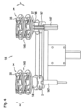
- a gripping and centering arrangement 144 can then be provided, as exemplary in Figure 4 is shown.
- the arrangement 144 has a total of two pairs 145 of two gripping devices 34 each with gripping elements 35, as described above.
- Each pair 145 of gripping devices 34 is assigned to a part of the measuring device 10, each with a camera 22, a first radiation source 40, and a second radiation source 50.
- Each pair 145 of gripping devices 34 is mounted on a rotating device 146 so as to be rotatable by 180° in the direction of arrows D.
- Each pair 145 of gripping devices 34 is further assigned a storage table 37, as described above.
- Each storage table 37 is designed to be height-adjustable by means of an adjusting device 147 and is arranged such that it is in a loading position according to Figure 2 (right half of Figure 4 ) or in a measuring position according to Figure 3 (left half of Figure 4 ).
- the second, in Figure 4 The gripping device 34, arranged in the background of the image, is positioned in relation to the associated elements of camera 22, first radiation source 40, and second radiation source 50 so that the measurement described below can take place.
- the front gripping device 34 can be loaded or unloaded with a lens 60 to be measured, as described below, while a lens (not shown) is held and measured in the rear gripping device 34.
- a lens 60 to be measured can be held in the front gripping device 34 and a fully measured lens 60 can be held in the rear gripping device 34 (not shown), so that this pair 145 can be rotated 180°.
- the lens 60 to be measured can then be measured as described below, while the fully measured lens 60 can be unloaded as described below.
- method step 102 the gripping elements 35 of the gripping device 34 are actuated such that the lens 60 is held in a clamping manner by means of the gripping elements 35, wherein the centering of the lens 60 is essentially maintained.
- the support table 37 is pivoted out of the measuring range of the camera lens 23 of the camera 22 in order to clear the measuring axis M for the camera lens 23.
- the gripping device 34, together with the lens 60 clamped therein is displaced upwards along the z-axis in the direction of the second radiation source 50 by means of the rack and pinion gear.
- the gripping device 34 of the device 10 according to the invention is now in a defined measuring position (cf. Figure 2 ). This measuring position can remain unchanged regardless of the properties of the optically active element to be measured in order to contribute to the standardization of the method according to the invention.
- each laser diode of the two groups 40a, 40b of laser diodes 41 emits a linear beam, in the exemplary embodiment, excitation radiation with a wavelength of 405 nm or 450 nm. These defined wavelengths can be filtered out of the radiation emitted by the laser diodes 41, for example, using a filter (not shown).
- the linear beams emitted by the laser diodes 41 are spaced apart by approximately 10 mm.
- the linear beams emitted by all eight laser diodes in the exemplary embodiment impinge on the material of the lens 60 and/or its coating 60' in the form of a line pattern of two groups of four lines each arranged at right angles to one another.
- the fluorescence radiation of the material of the lens 60 and/or its coating 60', with a wavelength of more than 405 nm or 450 nm, excited by the linear beams arranged in this way, is therefore emitted in the form of two groups of four spaced-apart lines each arranged at right angles to one another (i.e., in the form of a grid or checkered pattern).
- the fluorescent radiation emitted by the material of the lens 60 and/or its coating 60' thus forms a checkered or grid pattern of two times four fluorescent lines with a wavelength of more than 405 nm or 450 nm in the exemplary embodiment.
- This fluorescent radiation is captured by the camera lens 23 in method step 105 and, in the exemplary embodiment, detected by a CCD sensor of the camera 22. If the camera 22 or the camera lens 23 has a filter for absorbing or deflecting the excitation radiation emitted by the laser diodes 41, the fluorescent radiation can be detected particularly reliably and with little interference.
- the resulting measurement data are fed to an evaluation unit 70.
- the measurement data is evaluated using a known triangulation method (stripe projection as a 3D measurement method). This determines the spatial position of the concave underside 62 of the lens 60 in the exemplary embodiment.
- a known triangulation method stripe projection as a 3D measurement method.
- This determines the spatial position of the concave underside 62 of the lens 60 in the exemplary embodiment.
- the measurement result is unambiguous.
- symmetric lenses e.g., spherical lenses
- data on their edge contour is also required to determine their position in space.
- the device 10 according to the invention can be calibrated by carrying out the method described above with a flat glass as the measuring object.
- the second radiation source 50 (in the exemplary embodiment, a TFT-based LCD screen) emits rays in a defined pattern (e.g., a striped pattern) toward the upper side 61 of the lens 60, which is convex in the exemplary embodiment.
- the rays pass through the lens 60, wherein the defined pattern is modified according to the characteristics of the lens 60, in particular its contour, its edge contour, any markings (e.g., laser engravings), and/or any multifocal zones (e.g., bifocal or trifocal zones) of the lens 60.
- the resulting transmission radiation is captured in method step 107 by the camera lens 23 of the camera 22 and, in the exemplary embodiment, detected in the form of measurement signals by means of the CCD sensor of the camera 22.
- the measurement data resulting from this transmission measurement are fed to the evaluation unit 70 and evaluated.
- the device 10 according to the invention can be calibrated by carrying out the method described above with a flat glass as the measuring object.
- the second radiation source 50 (in the exemplary embodiment a TFT-based LCD screen) emits in method step 108 rays in the form of defined pixels in the direction of the convex upper side 61 of the lens 60 in the exemplary embodiment.
- the rays pass through the lens 60, being deflected depending on the optical properties of the lens 60.
- the resulting transmission radiation is captured in method step 109 by the camera lens 23 of the camera 22 and, in the exemplary embodiment, detected in the form of measuring points by means of the CCD sensor of the camera 22.
- a known ray tracing method is used in the exemplary embodiment (i.e., an algorithm based on the emission of rays for tracing the determined measuring points back to their source, i.e., the defined pixels).
- the resulting measurement points captured by camera 22 are correlated with the pixels arranged on the second radiation source 50 (i.e., the starting points of the rays captured in the form of measurement points).
- the second radiation source 50 is coded accordingly in a manner known per se.
- the measurement data resulting from the transmission measurement and the ray tracing method are fed to the evaluation unit 70.
- the defined pattern of the rays emitted by the second radiation source 50 is selected such that sufficient signal separation, i.e., sufficient resolution of the measurement signals, is achieved at the CCD sensor, so that, in the optimal case, each measurement signal can be evaluated.
- the evaluation of the measurement data yields the refractive power of the lens 60.
- the device 10 according to the invention can be calibrated by carrying out the method described above with a flat glass as the measurement object.
- the linking of these measurement data allows the determination of a planar evaluation of the refractive power of lens 60 (so-called "power map") in method step 110. This makes it possible, among other things, to distinguish between prisms incorporated into lens 60 as ordered and prism errors. This applies both to prism errors that arose during the shaping of the underside 62 of lens 60 and to prism errors that are detected due to incorrect positioning of lens 60 in device 10.
- the methods described above for determining the spatial position of the lens 60 (point 1) and for determining its parameters (point 2) can also be carried out deflectometrically.
- radiation emitted by a radiation source is used, to which the lens 60 is opaque.
- the radiation source is positioned such that the lens 60 reflects the radiation emitted by the radiation source in the direction of the measuring axis M, i.e., in the direction of the camera lens 23, so that the resulting Reflected radiation can be captured by the camera lens 23 and detected by the CCD sensor of the camera 22.
- the resulting measurement data is then evaluated in a conventional manner.
Landscapes
- Physics & Mathematics (AREA)
- General Physics & Mathematics (AREA)
- Chemical & Material Sciences (AREA)
- Analytical Chemistry (AREA)
- Geometry (AREA)
- Engineering & Computer Science (AREA)
- Computer Vision & Pattern Recognition (AREA)
- Investigating, Analyzing Materials By Fluorescence Or Luminescence (AREA)
- Length Measuring Devices By Optical Means (AREA)
- Eyeglasses (AREA)
- Analysing Materials By The Use Of Radiation (AREA)
Claims (13)
- Procédé de mesure d'au moins un objet optiquement actif (60) avec une face supérieure (61) et une face inférieure (62), l'au moins un objet optiquement actif (60) étant irradié avec un rayonnement de mesure et le rayonnement qui en résulte étant mesuré,au moins un rayonnement de mesure traversant l'objet optiquement actif (60) étant utilisé comme rayonnement de mesure et le rayonnement de transmission étant mesuré et/ou détecté comme rayonnement résultant,au moins un rayonnement d'excitation pour l'excitation d'un rayonnement de luminescence dans le matériau de l'objet optiquement actif (60) et/ou dans le matériau d'un revêtement (60') de l'objet optiquement actif (60) étant en outre utilisé comme rayonnement de mesure et le rayonnement de luminescence étant mesuré et/ou détecté comme rayonnement résultant,le rayonnement de luminescence résultant étant utilisé pour la triangulation de la/des surface(s) de la face supérieure irradiée (61) et/ou de la face inférieure irradiée (62) de l'objet optiquement actif (60), etle rayonnement de transmission résultant étant utilisé pour la détermination de la puissance de réfraction de l'objet optiquement actif (60) et/ou de grandeurs caractéristiques de l'objet optiquement actif (60).
- Procédé selon la revendication 1, caractérisé en ce qu'au moins un rayonnement pouvant être réfléchi par l'objet optiquement actif est en outre utilisé comme rayonnement de mesure et le rayonnement de réflexion est mesuré et/ou détecté comme rayonnement résultant.
- Procédé selon la revendication 2, caractérisé en ce que le rayonnement de réflexion résultant est utilisé pour la triangulation et/ou pour la mesure par déflecto-métrie de la/des surface(s) de la face supérieure irradiée (61) et/ou de la face inférieure irradiée (62) de l'objet optiquement actif (60).
- Procédé selon la revendication 2 ou 3, caractérisé en ce qu'au moins un rayonnement d'excitation pour l'excitation d'un rayonnement de fluorescence dans le matériau de l'objet optiquement actif (60) et/ou dans le matériau du revêtement (60') de l'objet optiquement actif (60) est utilisé.
- Procédé selon la revendication 2, caractérisé en ce que le rayonnement de réflexion résultant est utilisé pour la détermination de la puissance de réfraction de l'objet optiquement actif (60) et/ou de grandeurs caractéristiques de l'objet optiquement actif (60).
- Procédé selon l'une quelconque des revendications précédentes, caractérisé par l'évaluation à plat de la puissance de réfraction de l'objet optiquement actif (60).
- Procédé selon l'une quelconque des revendications précédentes, caractérisé en ce que la mesure au moyen du rayonnement de transmission et la mesure au moyen du rayonnement d'excitation sont réalisées simultanément.
- Appareil (10) de mesure d'au moins un objet optiquement actif (60), avec une source de rayonnement, un dispositif de mesure, des moyens (30) pour maintenir l'au moins un objet optiquement actif (60) entre la source de rayonnement et le dispositif de mesure,l'appareil (10) présentant au moins une première source de rayonnement (40) et au moins une deuxième source de rayonnement (50),l'appareil présentant au moins un dispositif de mesure et/ou de détection (20) ainsi qu'au moins un dispositif d'évaluation (70), etl'au moins une deuxième source de rayonnement (50) étant disposée de manière à être orientée vers une face supérieure (61) de l'objet optiquement actif (60) et étant conçue pour émettre un rayonnement traversant au moins l'objet optiquement actif (60),l'au moins une première source de rayonnement (40) étant disposée de manière à être orientée vers une face supérieure (61) ou une face inférieure (62) de l'objet optiquement actif (60) et étant conçue pour émettre un rayonnement d'excitation pour l'excitation d'un rayonnement de luminescence dans le matériau de l'objet optiquement actif (60) et/ou dans le matériau d'un revêtement (60') de l'objet optique (60), etl'appareil (10) étant conçu pour réaliser un procédé selon l'une quelconque des revendications précédentes.
- Appareil selon la revendication 8, caractérisé en ce que l'au moins une première source de rayonnement (40) est conçue pour émettre au moins un rayonnement d'excitation pour l'excitation d'un rayonnement de fluorescence dans le matériau de l'objet optiquement actif (60) et/ou dans le matériau du revêtement (60') de l'objet optiquement actif (60).
- Appareil selon la revendication 8 ou 9, caractérisé en ce que l'au moins une première source de rayonnement (40) est conçue pour exciter un rayonnement de luminescence en forme de grille et/ou en forme de trame.
- Appareil selon l'une quelconque des revendications 8 à 10, caractérisé en ce que l'au moins une première source de rayonnement (40) est conçue pour émettre un rayonnement pouvant être réfléchi au moins par l'objet optiquement actif.
- Appareil selon l'une quelconque des revendications 8 à 11, caractérisé en ce que l'au moins une deuxième source de rayonnement (50) est conçue pour émettre au moins un rayonnement sous forme de pixels et/ou sous forme de motifs.
- Appareil selon l'une quelconque des revendications 8 à 12, caractérisé en ce que l'au moins un dispositif de mesure et/ou de détection (20) et l'au moins une première source de rayonnement (40) sont disposés de manière à être orientés vers la même face supérieure (61) ou face inférieure (62) de l'objet optiquement actif (60).
Applications Claiming Priority (2)
| Application Number | Priority Date | Filing Date | Title |
|---|---|---|---|
| DE102018001385.6A DE102018001385A1 (de) | 2018-02-21 | 2018-02-21 | Vorrichtung und Verfahren zum Vermessen mindestens eines optisch wirksamen Gegenstands |
| DE102018007463.4A DE102018007463B4 (de) | 2018-09-04 | 2018-09-21 | Vorrichtung und Verfahren zur Linsenbearbeitung sowie Bearbeitungseinrichtung für Linsen |
Publications (2)
| Publication Number | Publication Date |
|---|---|
| EP3531067A1 EP3531067A1 (fr) | 2019-08-28 |
| EP3531067B1 true EP3531067B1 (fr) | 2025-04-02 |
Family
ID=65520036
Family Applications (1)
| Application Number | Title | Priority Date | Filing Date |
|---|---|---|---|
| EP19000092.7A Active EP3531067B1 (fr) | 2018-02-21 | 2019-02-20 | Dispositif et procédé de mesure d'au moins un objet optiquement actif |
Country Status (4)
| Country | Link |
|---|---|
| US (1) | US11067476B2 (fr) |
| EP (1) | EP3531067B1 (fr) |
| CN (1) | CN110174240B (fr) |
| HU (1) | HUE071584T2 (fr) |
Families Citing this family (7)
| Publication number | Priority date | Publication date | Assignee | Title |
|---|---|---|---|---|
| EP3588048A1 (fr) * | 2018-06-21 | 2020-01-01 | Essilor International (Compagnie Generale D'optique) | Procédé pour détecter un défaut dans une zone d'intérêt d'une lentille optique |
| CN119935501A (zh) * | 2019-01-10 | 2025-05-06 | 6超越6视觉有限公司 | 确定镜片的一个或多个参数的装置、系统和方法 |
| MX2024003074A (es) * | 2021-09-16 | 2024-03-27 | Schneider Gmbh & Co Kg | Procedimiento y aparato para el control de calidad de lentes oftalmicas. |
| TWI772216B (zh) | 2021-10-29 | 2022-07-21 | 合盈光電科技股份有限公司 | 檢測幾何元件紋理及幾何形貌與幾何中心的測量方法 |
| TWI852360B (zh) * | 2023-02-22 | 2024-08-11 | 望隼科技股份有限公司 | 鏡片檢測設備 |
| US20240428502A1 (en) * | 2023-06-21 | 2024-12-26 | Apple Inc. | Displays with Varying Update Frequencies for Different Content Types |
| DE102024126710A1 (de) | 2024-09-17 | 2026-03-19 | Schneider Gmbh & Co. Kg | Verfahren zur Vermessung von optischen Linsen und Vorrichtung hierzu |
Citations (1)
| Publication number | Priority date | Publication date | Assignee | Title |
|---|---|---|---|---|
| DE69726506T2 (de) * | 1996-01-10 | 2004-11-04 | Kabushiki Kaisha Topcon | Anordnungsbeurteilungsvorrichtung und system |
Family Cites Families (35)
| Publication number | Priority date | Publication date | Assignee | Title |
|---|---|---|---|---|
| DE4127094C2 (de) | 1991-08-16 | 1994-09-08 | Wernicke & Co Gmbh | Anlage zum Schleifen der optischen Oberflächen und/oder des Umfangsrandes von Brillengläsern |
| US5991018A (en) * | 1995-06-14 | 1999-11-23 | Kirin Beer Kabushiki Kaisha | Apparatus and method for inspecting coating layer |
| US5969370A (en) * | 1997-04-28 | 1999-10-19 | International Business Machines Corporation | Surface inspection tool |
| US5945685A (en) * | 1997-11-19 | 1999-08-31 | International Business Machines Corporation | Glass substrate inspection tool having a telecentric lens assembly |
| DE19837932C2 (de) | 1998-08-20 | 2000-09-07 | Bioshape Ag | Verfahren und Vorrichtung zur Ermittlung der Oberflächenform von biologischem Gewebe |
| IL132436A0 (en) * | 1999-10-18 | 2001-03-19 | Prolaser Ltd | Automatic attachment of a finishing block to an ophthalmic lens |
| DE10013648A1 (de) | 2000-03-18 | 2001-09-27 | Wernicke & Co Gmbh | Anlage zum Formbearbeiten der Ränder von Brillengläsern |
| CN1179204C (zh) * | 2000-08-11 | 2004-12-08 | 株式会社拓普康 | 折射能力测定方法及其装置 |
| FR2813391B1 (fr) | 2000-08-22 | 2002-11-29 | Essilor Int | Procede et appareil de mesure en transmission de la structure geometrique d'un composant optique |
| EP1605241A1 (fr) | 2004-06-09 | 2005-12-14 | Automation & Robotics | Appareil pour le controle des pièces transparentes ou réflechissantes |
| FR2878970B1 (fr) | 2004-12-03 | 2007-04-06 | Essilor Int | Dispositif de preparation automatique au montage de lentilles ophtalmiques permettant la prise en charge de plusieurs lentilles simultanement |
| US7277819B2 (en) * | 2005-10-31 | 2007-10-02 | Eastman Kodak Company | Measuring layer thickness or composition changes |
| DE102005057725B4 (de) | 2005-12-01 | 2019-06-13 | Schneider Gmbh & Co. Kg | Vorrichtung und Verfahren zum Bearbeiten einer Linse |
| US20120008103A1 (en) * | 2006-10-06 | 2012-01-12 | Iglobe Inc. | Ray Casting for Coherent Light Internal Projection Systems |
| US20080144001A1 (en) * | 2006-12-15 | 2008-06-19 | Bauke Heeg | Spectral imaging device |
| KR100844090B1 (ko) * | 2006-12-21 | 2008-07-04 | 주식회사 동구기업 | 글라스 렌즈의 회전식 자동 연마장치 |
| JP4279322B2 (ja) * | 2007-02-20 | 2009-06-17 | 三菱重工業株式会社 | 波長選択方法、膜厚計測方法、膜厚計測装置、及び薄膜シリコン系デバイスの製造システム |
| US8143600B2 (en) | 2008-02-18 | 2012-03-27 | Visiongate, Inc. | 3D imaging of live cells with ultraviolet radiation |
| JP2011075318A (ja) | 2009-09-29 | 2011-04-14 | Renesas Electronics Corp | レンズずれ測定装置、レンズずれ測定方法及び光モジュールの製造方法 |
| EP2489467A1 (fr) * | 2011-02-15 | 2012-08-22 | Schneider GmbH & Co. KG | Dispositif et procédé pour le traitement d'une lentille optique avec un dispositif de détection optique de la transition entre le matériau de la lentille et celui de la molette de glantage ou de la feuille pour déterminer le tracé du bord périphérique de la lentille |
| US9074874B2 (en) * | 2012-02-24 | 2015-07-07 | Litesentry Corporation | Coating detection on transparent sheet material |
| DE202012011690U1 (de) | 2012-03-09 | 2013-03-13 | Schneider Gmbh & Co. Kg | Anlage zum Bearbeiten optischer Linsen |
| US8976250B2 (en) * | 2012-05-01 | 2015-03-10 | Apple Inc. | Lens inspection system |
| EP2880398B1 (fr) | 2012-07-31 | 2018-03-28 | Essilor International | Procédé et système pour l'identification d'une caractéristique géométrique donnée d'un composant optique |
| US8836936B2 (en) * | 2013-02-05 | 2014-09-16 | Shenzhen China Star Optoelectronics Technology Co., Ltd | Inspecting device for detecting appearance of debris on a surface of a glass substrate, inspecting apparatus and method for conducting inspection |
| US20140273051A1 (en) * | 2013-03-15 | 2014-09-18 | Rakesh Reddy | Chemical sensing apparatus having multiple immobilized reagents |
| CN105492862B (zh) * | 2013-07-01 | 2021-08-10 | 萨科希瑞斯先进控制有限公司 | 用于光学地形状检测和/或检查物体的方法和设备 |
| DE102014100594A1 (de) * | 2014-01-20 | 2015-07-23 | Isra Surface Vision Gmbh | Vorrichtung zur Inspektion eines mit einer beschichteten Oberfläche versehenen Materials und entsprechendes Verfahren |
| WO2016095939A1 (fr) | 2014-12-19 | 2016-06-23 | Schneider Gmbh & Co. Kg | Procédé et dispositif d'usinage d'une lentille optique |
| US10718687B2 (en) * | 2015-06-25 | 2020-07-21 | Transitions Optical, Inc. | Inspection unit for photochromic ophthalmic lenses |
| US10788314B2 (en) * | 2016-01-07 | 2020-09-29 | Arkema Inc. | Object position independent method to measure the thickness of coatings deposited on curved objects moving at high rates |
| JP6769605B2 (ja) * | 2016-08-16 | 2020-10-14 | 株式会社トーメーコーポレーション | レンズメータ |
| CN106840001B (zh) * | 2017-01-16 | 2019-02-01 | 中国科学院上海光学精密机械研究所 | 光学透镜中心厚度的非接触式测量装置和测量方法 |
| US10732336B2 (en) * | 2017-02-02 | 2020-08-04 | Corning Incorporated | Method of assembling optical systems and minimizing retardance distortions in optical assemblies |
| US10634618B2 (en) * | 2018-01-23 | 2020-04-28 | Hong Kong Applied Science and Technology Research Institute Company Limited | Apparatus and a method for inspecting a light transmissible optical component |
-
2019
- 2019-02-20 EP EP19000092.7A patent/EP3531067B1/fr active Active
- 2019-02-20 US US16/280,771 patent/US11067476B2/en active Active
- 2019-02-20 HU HUE19000092A patent/HUE071584T2/hu unknown
- 2019-02-21 CN CN201910129388.8A patent/CN110174240B/zh active Active
Patent Citations (1)
| Publication number | Priority date | Publication date | Assignee | Title |
|---|---|---|---|---|
| DE69726506T2 (de) * | 1996-01-10 | 2004-11-04 | Kabushiki Kaisha Topcon | Anordnungsbeurteilungsvorrichtung und system |
Also Published As
| Publication number | Publication date |
|---|---|
| CN110174240A (zh) | 2019-08-27 |
| US20190257714A1 (en) | 2019-08-22 |
| US11067476B2 (en) | 2021-07-20 |
| HUE071584T2 (hu) | 2025-09-28 |
| CN110174240B (zh) | 2023-06-16 |
| EP3531067A1 (fr) | 2019-08-28 |
Similar Documents
| Publication | Publication Date | Title |
|---|---|---|
| EP3531067B1 (fr) | Dispositif et procédé de mesure d'au moins un objet optiquement actif | |
| EP1597539B1 (fr) | Procede et systeme optique permettant de mesurer la topographie d'un objet de mesure | |
| EP3581881B1 (fr) | Mesure de surface au moyen de la fluorescence excitée | |
| DE102019116309A1 (de) | Verfahren und Vorrichtung zur kontrollierten Bearbeitung eines Werkstücks | |
| EP1354234B1 (fr) | Systeme optique et procede d'activation et de mesure de la fluorescence sur ou dans des echantillons traites avec des colorants fluorescents | |
| DE102014005281B4 (de) | Bestimmung der Position zumindest eines Brillenglases im Raum | |
| DE3007125A1 (de) | Vorrichtung und verfahren zur bestimmung der brechungseigenschaften einer testlinse | |
| EP3569976B1 (fr) | Tête de mesure de rugosité, dispositif avec ladite tête de mesure et utilisation correspondante | |
| EP3182062B1 (fr) | Étalonnage d'un interféromètre | |
| EP1880698A1 (fr) | Dispositif ophthalmologique | |
| DE102017107343A1 (de) | Verfahren und Vorrichtung zum Betreiben eines optischen Abstandssensors | |
| DE102014007201A1 (de) | Vorrichtung und Verfahren zur geometrischen Vermessung eines Objekts | |
| DE102017211680B4 (de) | Optischer Sensor und Verfahren zur Positionierung, Fokussierung und Beleuchtung | |
| DE102021118327A1 (de) | Messkamera und Verfahren zur zweidimensionalen Vermessung von Gegenständen | |
| EP0848810A1 (fr) | Procede et dispositif de mesure des proprietes optiques de verres de lunettes au moyen d'un detecteur optique de dessins graves dans les verres de lunettes | |
| EP3433669B1 (fr) | Procedure et dispositif pour la determination des coordonnees 3d d'un point determine d'un objet | |
| DE102014119436B4 (de) | Koordinatenmessgerät und Verfahren zum Bestimmen von geometrischen Eigenschaften eines Messobjekts unter Verwendung einer Lichtfeldkamera | |
| DE102018001385A1 (de) | Vorrichtung und Verfahren zum Vermessen mindestens eines optisch wirksamen Gegenstands | |
| WO2014023346A1 (fr) | Dispositif doté d'une référence optique interne | |
| EP3388780B1 (fr) | Procédé et dispositif de référencement de la position d'au moins un point sur un objet transparent ou dans ce dernier | |
| WO2018054888A1 (fr) | Procédé et dispositif de mesurage photogrammétrique stéréographique de différents objets | |
| EP1459033A2 (fr) | Procede de mesure tridimensionnelle d'une surface | |
| WO2010015694A1 (fr) | Procédé et dispositif de contrôle pour l'examen optique de surfaces d'objets, notamment de bords de tranches de silicium | |
| EP1136787B1 (fr) | Reproduction d'un objet avec compensation de la distance ( taille, couleur ) | |
| WO2022049169A1 (fr) | Procédé d'analyse de la surface d'une pièce dans le cadre d'un processus d'usinage laser et dispositif d'analyse destiné à analyser la surface d'une pièce |
Legal Events
| Date | Code | Title | Description |
|---|---|---|---|
| PUAI | Public reference made under article 153(3) epc to a published international application that has entered the european phase |
Free format text: ORIGINAL CODE: 0009012 |
|
| STAA | Information on the status of an ep patent application or granted ep patent |
Free format text: STATUS: THE APPLICATION HAS BEEN PUBLISHED |
|
| AK | Designated contracting states |
Kind code of ref document: A1 Designated state(s): AL AT BE BG CH CY CZ DE DK EE ES FI FR GB GR HR HU IE IS IT LI LT LU LV MC MK MT NL NO PL PT RO RS SE SI SK SM TR |
|
| AX | Request for extension of the european patent |
Extension state: BA ME |
|
| STAA | Information on the status of an ep patent application or granted ep patent |
Free format text: STATUS: REQUEST FOR EXAMINATION WAS MADE |
|
| 17P | Request for examination filed |
Effective date: 20200228 |
|
| RBV | Designated contracting states (corrected) |
Designated state(s): AL AT BE BG CH CY CZ DE DK EE ES FI FR GB GR HR HU IE IS IT LI LT LU LV MC MK MT NL NO PL PT RO RS SE SI SK SM TR |
|
| STAA | Information on the status of an ep patent application or granted ep patent |
Free format text: STATUS: EXAMINATION IS IN PROGRESS |
|
| 17Q | First examination report despatched |
Effective date: 20221121 |
|
| GRAP | Despatch of communication of intention to grant a patent |
Free format text: ORIGINAL CODE: EPIDOSNIGR1 |
|
| STAA | Information on the status of an ep patent application or granted ep patent |
Free format text: STATUS: GRANT OF PATENT IS INTENDED |
|
| INTG | Intention to grant announced |
Effective date: 20241024 |
|
| RIN1 | Information on inventor provided before grant (corrected) |
Inventor name: SCHNEIDER, SEBASTIAN Inventor name: SCHNEIDER, GUNTER Inventor name: HUTTENHUIS, STEPHAN |
|
| GRAS | Grant fee paid |
Free format text: ORIGINAL CODE: EPIDOSNIGR3 |
|
| P01 | Opt-out of the competence of the unified patent court (upc) registered |
Free format text: CASE NUMBER: APP_3106/2025 Effective date: 20250120 |
|
| GRAA | (expected) grant |
Free format text: ORIGINAL CODE: 0009210 |
|
| STAA | Information on the status of an ep patent application or granted ep patent |
Free format text: STATUS: THE PATENT HAS BEEN GRANTED |
|
| AK | Designated contracting states |
Kind code of ref document: B1 Designated state(s): AL AT BE BG CH CY CZ DE DK EE ES FI FR GB GR HR HU IE IS IT LI LT LU LV MC MK MT NL NO PL PT RO RS SE SI SK SM TR |
|
| REG | Reference to a national code |
Ref country code: GB Ref legal event code: FG4D Free format text: NOT ENGLISH |
|
| REG | Reference to a national code |
Ref country code: CH Ref legal event code: EP |
|
| REG | Reference to a national code |
Ref country code: IE Ref legal event code: FG4D Free format text: LANGUAGE OF EP DOCUMENT: GERMAN |
|
| REG | Reference to a national code |
Ref country code: DE Ref legal event code: R096 Ref document number: 502019013138 Country of ref document: DE |
|
| REG | Reference to a national code |
Ref country code: NL Ref legal event code: MP Effective date: 20250402 |
|
| PG25 | Lapsed in a contracting state [announced via postgrant information from national office to epo] |
Ref country code: NL Free format text: LAPSE BECAUSE OF FAILURE TO SUBMIT A TRANSLATION OF THE DESCRIPTION OR TO PAY THE FEE WITHIN THE PRESCRIBED TIME-LIMIT Effective date: 20250402 |
|
| REG | Reference to a national code |
Ref country code: HU Ref legal event code: AG4A Ref document number: E071584 Country of ref document: HU |
|
| PG25 | Lapsed in a contracting state [announced via postgrant information from national office to epo] |
Ref country code: FI Free format text: LAPSE BECAUSE OF FAILURE TO SUBMIT A TRANSLATION OF THE DESCRIPTION OR TO PAY THE FEE WITHIN THE PRESCRIBED TIME-LIMIT Effective date: 20250402 Ref country code: ES Free format text: LAPSE BECAUSE OF FAILURE TO SUBMIT A TRANSLATION OF THE DESCRIPTION OR TO PAY THE FEE WITHIN THE PRESCRIBED TIME-LIMIT Effective date: 20250402 Ref country code: PT Free format text: LAPSE BECAUSE OF FAILURE TO SUBMIT A TRANSLATION OF THE DESCRIPTION OR TO PAY THE FEE WITHIN THE PRESCRIBED TIME-LIMIT Effective date: 20250804 |
|
| REG | Reference to a national code |
Ref country code: LT Ref legal event code: MG9D |
|
| PG25 | Lapsed in a contracting state [announced via postgrant information from national office to epo] |
Ref country code: GR Free format text: LAPSE BECAUSE OF FAILURE TO SUBMIT A TRANSLATION OF THE DESCRIPTION OR TO PAY THE FEE WITHIN THE PRESCRIBED TIME-LIMIT Effective date: 20250703 Ref country code: NO Free format text: LAPSE BECAUSE OF FAILURE TO SUBMIT A TRANSLATION OF THE DESCRIPTION OR TO PAY THE FEE WITHIN THE PRESCRIBED TIME-LIMIT Effective date: 20250702 |
|
| PG25 | Lapsed in a contracting state [announced via postgrant information from national office to epo] |
Ref country code: PL Free format text: LAPSE BECAUSE OF FAILURE TO SUBMIT A TRANSLATION OF THE DESCRIPTION OR TO PAY THE FEE WITHIN THE PRESCRIBED TIME-LIMIT Effective date: 20250402 |
|
| PG25 | Lapsed in a contracting state [announced via postgrant information from national office to epo] |
Ref country code: BG Free format text: LAPSE BECAUSE OF FAILURE TO SUBMIT A TRANSLATION OF THE DESCRIPTION OR TO PAY THE FEE WITHIN THE PRESCRIBED TIME-LIMIT Effective date: 20250402 |
|
| PG25 | Lapsed in a contracting state [announced via postgrant information from national office to epo] |
Ref country code: HR Free format text: LAPSE BECAUSE OF FAILURE TO SUBMIT A TRANSLATION OF THE DESCRIPTION OR TO PAY THE FEE WITHIN THE PRESCRIBED TIME-LIMIT Effective date: 20250402 |
|
| PG25 | Lapsed in a contracting state [announced via postgrant information from national office to epo] |
Ref country code: RS Free format text: LAPSE BECAUSE OF FAILURE TO SUBMIT A TRANSLATION OF THE DESCRIPTION OR TO PAY THE FEE WITHIN THE PRESCRIBED TIME-LIMIT Effective date: 20250702 |
|
| PG25 | Lapsed in a contracting state [announced via postgrant information from national office to epo] |
Ref country code: IS Free format text: LAPSE BECAUSE OF FAILURE TO SUBMIT A TRANSLATION OF THE DESCRIPTION OR TO PAY THE FEE WITHIN THE PRESCRIBED TIME-LIMIT Effective date: 20250802 |
|
| PG25 | Lapsed in a contracting state [announced via postgrant information from national office to epo] |
Ref country code: LV Free format text: LAPSE BECAUSE OF FAILURE TO SUBMIT A TRANSLATION OF THE DESCRIPTION OR TO PAY THE FEE WITHIN THE PRESCRIBED TIME-LIMIT Effective date: 20250402 |
|
| REG | Reference to a national code |
Ref country code: DE Ref legal event code: R097 Ref document number: 502019013138 Country of ref document: DE |
|
| PG25 | Lapsed in a contracting state [announced via postgrant information from national office to epo] |
Ref country code: SM Free format text: LAPSE BECAUSE OF FAILURE TO SUBMIT A TRANSLATION OF THE DESCRIPTION OR TO PAY THE FEE WITHIN THE PRESCRIBED TIME-LIMIT Effective date: 20250402 Ref country code: DK Free format text: LAPSE BECAUSE OF FAILURE TO SUBMIT A TRANSLATION OF THE DESCRIPTION OR TO PAY THE FEE WITHIN THE PRESCRIBED TIME-LIMIT Effective date: 20250402 |
|
| PG25 | Lapsed in a contracting state [announced via postgrant information from national office to epo] |
Ref country code: CZ Free format text: LAPSE BECAUSE OF FAILURE TO SUBMIT A TRANSLATION OF THE DESCRIPTION OR TO PAY THE FEE WITHIN THE PRESCRIBED TIME-LIMIT Effective date: 20250402 |
|
| PG25 | Lapsed in a contracting state [announced via postgrant information from national office to epo] |
Ref country code: EE Free format text: LAPSE BECAUSE OF FAILURE TO SUBMIT A TRANSLATION OF THE DESCRIPTION OR TO PAY THE FEE WITHIN THE PRESCRIBED TIME-LIMIT Effective date: 20250402 |
|
| PG25 | Lapsed in a contracting state [announced via postgrant information from national office to epo] |
Ref country code: SK Free format text: LAPSE BECAUSE OF FAILURE TO SUBMIT A TRANSLATION OF THE DESCRIPTION OR TO PAY THE FEE WITHIN THE PRESCRIBED TIME-LIMIT Effective date: 20250402 Ref country code: RO Free format text: LAPSE BECAUSE OF FAILURE TO SUBMIT A TRANSLATION OF THE DESCRIPTION OR TO PAY THE FEE WITHIN THE PRESCRIBED TIME-LIMIT Effective date: 20250402 |
|
| PLBE | No opposition filed within time limit |
Free format text: ORIGINAL CODE: 0009261 |
|
| STAA | Information on the status of an ep patent application or granted ep patent |
Free format text: STATUS: NO OPPOSITION FILED WITHIN TIME LIMIT |
|
| REG | Reference to a national code |
Ref country code: CH Ref legal event code: L10 Free format text: ST27 STATUS EVENT CODE: U-0-0-L10-L00 (AS PROVIDED BY THE NATIONAL OFFICE) Effective date: 20260211 |
|
| REG | Reference to a national code |
Ref country code: CH Ref legal event code: U11 Free format text: ST27 STATUS EVENT CODE: U-0-0-U10-U11 (AS PROVIDED BY THE NATIONAL OFFICE) Effective date: 20260301 |
|
| 26N | No opposition filed |
Effective date: 20260105 |
|
| PGFP | Annual fee paid to national office [announced via postgrant information from national office to epo] |
Ref country code: HU Payment date: 20260213 Year of fee payment: 8 |
|
| PGFP | Annual fee paid to national office [announced via postgrant information from national office to epo] |
Ref country code: DE Payment date: 20260217 Year of fee payment: 8 |
|
| PGFP | Annual fee paid to national office [announced via postgrant information from national office to epo] |
Ref country code: IT Payment date: 20260227 Year of fee payment: 8 |
|
| PGFP | Annual fee paid to national office [announced via postgrant information from national office to epo] |
Ref country code: FR Payment date: 20260223 Year of fee payment: 8 |
|
| PGFP | Annual fee paid to national office [announced via postgrant information from national office to epo] |
Ref country code: CH Payment date: 20260301 Year of fee payment: 8 |