EP3531368A1 - Analyse de réseau de distribution public - Google Patents
Analyse de réseau de distribution public Download PDFInfo
- Publication number
- EP3531368A1 EP3531368A1 EP18157903.8A EP18157903A EP3531368A1 EP 3531368 A1 EP3531368 A1 EP 3531368A1 EP 18157903 A EP18157903 A EP 18157903A EP 3531368 A1 EP3531368 A1 EP 3531368A1
- Authority
- EP
- European Patent Office
- Prior art keywords
- temperature
- flow
- utility
- distribution network
- time series
- Prior art date
- Legal status (The legal status is an assumption and is not a legal conclusion. Google has not performed a legal analysis and makes no representation as to the accuracy of the status listed.)
- Granted
Links
Images


Classifications
-
- G—PHYSICS
- G06—COMPUTING OR CALCULATING; COUNTING
- G06Q—INFORMATION AND COMMUNICATION TECHNOLOGY [ICT] SPECIALLY ADAPTED FOR ADMINISTRATIVE, COMMERCIAL, FINANCIAL, MANAGERIAL OR SUPERVISORY PURPOSES; SYSTEMS OR METHODS SPECIALLY ADAPTED FOR ADMINISTRATIVE, COMMERCIAL, FINANCIAL, MANAGERIAL OR SUPERVISORY PURPOSES, NOT OTHERWISE PROVIDED FOR
- G06Q50/00—Information and communication technology [ICT] specially adapted for implementation of business processes of specific business sectors, e.g. utilities or tourism
- G06Q50/06—Energy or water supply
-
- F—MECHANICAL ENGINEERING; LIGHTING; HEATING; WEAPONS; BLASTING
- F24—HEATING; RANGES; VENTILATING
- F24D—DOMESTIC- OR SPACE-HEATING SYSTEMS, e.g. CENTRAL HEATING SYSTEMS; DOMESTIC HOT-WATER SUPPLY SYSTEMS; ELEMENTS OR COMPONENTS THEREFOR
- F24D10/00—District heating systems
-
- G—PHYSICS
- G01—MEASURING; TESTING
- G01K—MEASURING TEMPERATURE; MEASURING QUANTITY OF HEAT; THERMALLY-SENSITIVE ELEMENTS NOT OTHERWISE PROVIDED FOR
- G01K17/00—Measuring quantity of heat
- G01K17/06—Measuring quantity of heat conveyed by flowing media, e.g. in heating systems e.g. the quantity of heat in a transporting medium, delivered to or consumed in an expenditure device
-
- G—PHYSICS
- G06—COMPUTING OR CALCULATING; COUNTING
- G06Q—INFORMATION AND COMMUNICATION TECHNOLOGY [ICT] SPECIALLY ADAPTED FOR ADMINISTRATIVE, COMMERCIAL, FINANCIAL, MANAGERIAL OR SUPERVISORY PURPOSES; SYSTEMS OR METHODS SPECIALLY ADAPTED FOR ADMINISTRATIVE, COMMERCIAL, FINANCIAL, MANAGERIAL OR SUPERVISORY PURPOSES, NOT OTHERWISE PROVIDED FOR
- G06Q10/00—Administration; Management
- G06Q10/06—Resources, workflows, human or project management; Enterprise or organisation planning; Enterprise or organisation modelling
- G06Q10/063—Operations research, analysis or management
-
- H—ELECTRICITY
- H04—ELECTRIC COMMUNICATION TECHNIQUE
- H04L—TRANSMISSION OF DIGITAL INFORMATION, e.g. TELEGRAPHIC COMMUNICATION
- H04L41/00—Arrangements for maintenance, administration or management of data switching networks, e.g. of packet switching networks
- H04L41/14—Network analysis or design
- H04L41/142—Network analysis or design using statistical or mathematical methods
-
- H—ELECTRICITY
- H04—ELECTRIC COMMUNICATION TECHNIQUE
- H04L—TRANSMISSION OF DIGITAL INFORMATION, e.g. TELEGRAPHIC COMMUNICATION
- H04L41/00—Arrangements for maintenance, administration or management of data switching networks, e.g. of packet switching networks
- H04L41/14—Network analysis or design
- H04L41/145—Network analysis or design involving simulating, designing, planning or modelling of a network
-
- H—ELECTRICITY
- H04—ELECTRIC COMMUNICATION TECHNIQUE
- H04L—TRANSMISSION OF DIGITAL INFORMATION, e.g. TELEGRAPHIC COMMUNICATION
- H04L67/00—Network arrangements or protocols for supporting network services or applications
- H04L67/01—Protocols
- H04L67/12—Protocols specially adapted for proprietary or special-purpose networking environments, e.g. medical networks, sensor networks, networks in vehicles or remote metering networks
Definitions
- the present invention relates to analytics of data collected by use of advanced metering infrastructures, especially analytics of data from consumption meters in a district heating utility distribution network.
- Utility companies desire to have a real time overview of their distribution network in terms of current state and performance. This enables the utility company to respond immediately to anomalies, and to monitor the quality of the delivered utility.
- AMI Advanced Metering Infrastructure
- the AMI systems are evolving from systems collecting data from the utility meters infrequently or ad hoc for billing purposes to systems collecting time series of data. Such time series of data are suitable for not only billing but also for analytics and modelling, with the purpose of optimizing the utility distribution network and business.
- This evolvement has started in the field of electricity utilities, where the mains powered meters have sufficient energy supply to transmit large amounts of data suitable for advanced analytics.
- Battery operated meters such as water meters, heat meters, cooling meters or gas meters, are often designed for a lifetime of 16-20 years without a battery change, the amount of data that can be delivered from meters under these constraints is thus very limited.
- Communication and battery technologies have improved and Collection of Increased amounts of data from battery operated utility meters is however now becoming a reality. The use of these data for analytics and modelling is becoming a valuable element in optimizing production, distribution and consumption of the delivered utility.
- Utility companies have previously focused on using the collected data to improve the energy performance of individual buildings.
- district heating becomes more complex, integrating many different heat sources, it is increasingly important for utilities to have an optimized infrastructure.
- An optimized distribution network presents opportunities for significant cost savings for e.g. district heating utilities in particularly two areas: reducing heat loss and improving asset management.
- Using the data such as flow, temperature and pressure measured by the utility meters will however provide a vast number of measurements from all end points of the distribution network.
- This data could facilitate a data driven model of the distribution network.
- Such a model may be used to estimate various parameters which are relevant in order to monitor and optimize the distribution and supply quality in the network, in real time, by integrating with the head end system.
- the model may be used for asset management and distribution network expansion.
- the limited amount of data that can be delivered from battery operated meters through an AMI system and the fact that the data often not are coincident limits the accuracy of the results and put constraints to the use of the results.
- the method is advantageous for determining flow rate and temperature of the fluid inside a distribution line such as a flow pipe.
- the method may be used for calculating the temperature at one or a multitude of selected positions along the distribution lines of the distribution network.
- the individual positions may be selected to concern the forward flow or the return flow.
- the selection of positions may be performed by an operator selecting single or groups of positions or by a computer implemented method selecting multiple positions for which the temperature and / or flow rate are to be visualized e.g. on a map including data from a Geographical Information System (GIS).
- GIS Geographical Information System
- the temperature and flow rate of the fluid at a selected position calculated by the method are estimates. The certainty of the estimates will depend on the quality of the meter data time series available for the calculations.
- the quality of the meter data is determined by factors such as sampling rate, resolution, concurrency of samples etc.
- Flow and temperature information derived from the meter data time series shall be construed to include any metric directly included in or derived from the meter data. These metrics may include absolute values, relative values, accumulated values and statistical metrics such as first, second and third moment of relevant parameters measured by the utility meter or any sensor associated to the utility meter or Advanced Metering Infrastructure (AMI).
- the smart utility meter may be a legal meter, i.e. a meter which is subdued to regulatory demands. Such regulatory demands may be demands to the precision of the measurements.
- the smart utility meter may be a heat meter, cooling meter or another type energy meter for measuring thermal energy.
- the topology of the utility distribution network describes the network including nodes of connecting distribution lines and consumer service lines. Other elements of the distribution network, such as shunts between forward flow and return flow may also be included in the topology. Accurate and detailed description of the topology results in accurate estimates of flow rate and temperature.
- a continuous time domain calculation may however not be easy implementable in a utility meter.
- a utility meter comprising a flow meter, such as an ultrasonic flow meter based on the transit time principle, does not provide a continuous signal representing the flow, rather a sequence of time discrete samples of the flow is provide.
- Using statistical metrics such as a volume weighted temperature and the average flow for the calculations of flow rate and temperature in the utility distribution network has the advantage that the meter data time series may be sampled with a long sampling interval.
- the method is adequate in systems where the collected meter data time series has a sampling interval being larger than 10 minutes.
- Even systems providing meter data sampled with intervals of up to 30 minutes or even up to 60 minutes provide accurate results.
- the energy consumption by the consumers are sufficiently high even meter data time series sampled with an interval of 12 - 48 hours will result in flow rate and temperature estimates with an accuracy suitable for modelling the utility distribution network and detection of malfunctions.
- Especially meter data time series sampled with an interval of 24 hours have, when used by the disclosed method, proven as sufficient for providing accurate and useful results and models of the utility distribution network.
- the method may be extended with a step wherein the flow rate and temperature is calculated for a number of reference points to obtain a first set of flow-temperature estimates, the first set of flow-temperature estimates are subsequently used as flow-temperature data sets for calculating a second set of flow-temperature estimates estimating temperature and flow rate at the position of the utility meters.
- the reference points may be any point in the distribution network serving as a feed point of a sufficient number of consumers with individual smart utility meters.
- a reference point may serve as a feed point for as few as 10 consumers, however more precise estimates for the reference point will be achieved if at least 10 - 50 preferably up to 100 consumers are fed from the selected reference point.
- Reference points may even be selected at points in the utility distribution network feeding hundreds of consumers such as 100 - 1000 consumers to achieve an improved accuracy on the estimates.
- the second set of flow-temperature estimates is compared to the flow-temperature data sets derived from the collected meter data time series, to detect potential anomalies in the utility distribution network. Comparing the measured flow and temperature data to the estimated values obtained by this method has the effect of identifying sections of the utility distribution network for which the heat loss deviates from the expected.
- the temperature of the fluid in the distribution line is determined by use of methods based on graph theory and the utility distribution network is described in the terms of a graph object.
- Graph theory is the study of graphs, which are mathematical structures used to model pairwise relations between objects, graph theory is especially used within the area of discrete mathematics and is well described in literature.
- Other adequate mathematical methods for calculating flow and temperature in the utility distribution network may however be used.
- To obtain reliable results in more complex network topologies it may be necessary to implement a version of the method in which the temperature and / or the flow rate is calculated using one or more optimization algorithms. Recursive calculations and mathematical optimization principles may improve the accuracy of the resulting estimates.
- the diameter of the distribution lines is included in the calculations and the flow speed of the fluid in the distribution lines further is calculated. Knowing the flow speed in the distribution network enables functionalities wherein the transit time of the fluid from the utility plant to the selected position in the distribution network further is calculated. The flow speed may further be presented on a map show geographical information including the utility distribution network.
- a second aspect of the invention includes a system comprising multiple smart utility meters, an advanced metering infrastructure and a head end system, wherein the head end system is arranged to use the method described above to create a model of the utility distribution network by determining the flow rate and temperature of the fluid in the utility distribution network.
- solutions wherein the head end system is arranged to project the model onto GIS-data showing the utility distribution network may be provided.
- Such a solution may further be arranged to support placement of virtual probes at a position of the utility distribution network to display estimated parameters for the specific location.
- the disclosed method for determining flow and temperature estimates at any position in a utility distribution network of a district heating utility comprises the main steps of generating meter data, collecting meter data, describing the utility distribution network, calculate flow and temperature estimates at any position in the network.
- the method may further be extended by adding a step of comparing the resulting estimates to the collected data for detection of irregularities.
- a district heating utility distribution network including an Advanced Meter Reading (AMI) System is shown.
- Each consumer premises 106 is connected to the utility plant 100 via the district heating utility distribution network including distribution lines 102, 103 and consumer service lines 107.
- the connection includes a forward flow 102 and a return flow 103.
- the fluid in the pipes is heated at the district heating utility plant 100 and the energy is consumed by cooling down the fluid delivered by the forward 102 flow and returning the cooled down fluid in the return flow 103.
- the distribution network including distribution- and consumer service lines 102, 103, 107 are thermic isolated from the surroundings to minimize heat loss.
- a utility meter M such as an ultrasonic energy meter or another type of energy meter, measures the energy consumed.
- the utility meter M measures at least the forward and return temperatures of the fluid and the volume / flow rate of the fluid. Knowing the before mentioned temperatures and volume, the energy consumption can be calculated.
- the utility meters M are connected to a Head End System (HES) 104 using the AMI.
- the utility meters M may deliver any data obtained by the meter or external sensors to the HES 104, however the capacity of the AMI and the battery capacity of the utility meters M will limit the amount of data that can be delivered to the HES 104.
- the AMI may use any suitable technology for carrying data from the utility meter M to the HES 104 over one or more local area networks or wide area networks including connections to the open internet 105.
- a number of intermediate network devices such as data collectors 101, repeaters, routers gateways etc.
- the AMI may be a part of the communication paths between the utility meter M and HES 104.
- the AMI may use any suitable wireless technology (e.g. wireless M-Bus, Narrow band loT, SigFox, any cellular technologies or proprietary communication protocols) or any wired communication technologies (e.g. wired M-Bus, LON, Ethernet).
- meter data time series MD includes flow and temperature data set consisting of flow data and temperature data, also referred to as flow-temperature data sets QT_M in the following.
- the flow-temperature data sets QT_M are measured by the utility meters M at specific locations, including consumer premises 106 and collected by means of an Advanced Metering Infrastructure AMI.
- Distribution network model data DNMD comprises the topology of the distribution network, pipe dimensions, pipe lengths, coefficient of heat loss in the pipes.
- Distribution network model data DNMD cover all distribution lines from main utility distribution lines 102, 103 down to the consumer service line 107 for each consumer.
- the method includes an estimation block EST, which perform standard fluid- and thermodynamic calculations on the input data. Output from the estimation block EST is flow-temperature estimates QT_EST for specific locations in the utility distribution network.
- the flow-temperature estimates QT_EST are outputted from the method and may be used for further analytics or for direct visualization e.g. in a Geographical Information System (GIS).
- GIS Geographical Information System
- the flow-temperature estimates QT_EST are compared to the meter data MD as collected from the utility meters M to identify discrepancies QT_ERROR, that indicates malicious conditions in the distribution network.
- flow-temperature data sets QT_M measured by the utility meters M as input to the estimation block EST requires a high degree of concurrency of the meter data MD samples to obtain accurate estimates. Further, as the demand for energy at the consumer is varying the flow will vary accordingly and variations in the flow will cause variations in the forward and return temperatures. Thus frequent samples of flow-temperature data sets QT_M is required to get a useful output from the estimation block EST. In other words, concurrent and frequently sampled meter data time series MD from the population of meters is needed to achieve accurate flow-temperature estimates QT_EST from the estimation block EST of this method. This is in adverse to the capabilities of battery operated meters which have limited capacity for delivering data through the bandwidth limited AMI.
- the meter data time series MD used by the modified method of fig. 3 includes two metrics calculated by the meter.
- a first metric is the Integrated Flow Temperature Product (IFTP), denoted ⁇
- a second metric is the accumulated volume, denoted V.
- IFTP Integrated Flow Temperature Product
- V the accumulated volume
- the mean flow Q_AVG and the flow-weighted temperature T_VOL are suitable as input to the estimation block EST.
- the computation Q_AVG and T_VOL is performed by the converter block CONV.
- Q_AVG and T_VOL as the input to the estimation block EST, the accuracy of the resulting flow-temperature estimates QT_EST significantly improves compared to using time discrete samples of flow and temperature. This effect is especially prominent when using meter data time series MD sampled using a long sampling interval. Further, the accuracy of the resulting flow-temperature estimates QT_EST are less sensitive to lack of concurrency between meter data series MD sampled across the population of utility meters M when based on the IFTP ⁇ and the accumulated volume V.
- sampling interval may be increased significantly while still obtaining accurate flow-temperature estimates QT_EST.
- Sampling intervals in the range from 5 to 60 minutes is sufficient to obtain flow-temperature estimates QT_EST with a high accuracy.
- Even by using sampling intervals in the range from 1 to 24 hours the resulting flow-temperature estimates QT_EST has the accuracy required to be used for modelling and analysing the utility distribution network.
- Increasing the sampling interval has the advantage that the amount of transmitted data is reduced, which reduce energy and bandwidth consumption for transferring data through the AMI.
- the utility meters M are installed at the consumer premises 106 connected to the distribution lines throughout the edges of the network.
- the utility meters M usually measure the consumed energy for billing purposes as well as other parameters such as the accumulated volume of fluid flowing in and out of the consuming entity.
- the sampling interval for flow and temperature may vary depending on the type of utility meter M; a typical sampling interval will be in the range from 1 to 64 seconds. Sampling of flow rate and temperature does not need to be sampled coincidently; the sampling of the two parameters may e.g. be shifted by half a sampling period.
- the utility meter M will sample and store time series of meter data MD including the IFTP ⁇ and the accumulated volume V along with time stamps indicating the sampling time in the memory of the utility meter M.
- the sampling interval of the time series of data is typically in the range from 1 minute to one hour or even up to 24 hours.
- the storage interval may be fixed or variable and will depend on the utility meter M storage capacity.
- the time series of meter data MD will be collected by an AMI infrastructure.
- the utility meter M may autonomously transmit the current meter data to the AMI and a receiving device may establish a timestamped time series of meter data MD.
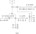
- the time series of data from all the relevant meters is processed by the converter block CONV as previously described and used by the by the estimation block EST to calculate the flow rate and temperature at nodes N1, N2, N3, N4, N5 of the distribution network, as shown in fig. 4 .
- the nodes shown in Fig. 4 are points where distribution lines of the utility distribution network are connected, however, flow rate and temperature may also be calculated at other positions of the network.
- the flow rate and temperature of the fluid in a utility distribution line can thus be calculated for any position in the utility distribution network. These results may be used for modelling the utility distribution network, by creating a model describing how flow rate and temperature changes throughout the utility distribution network.
- the heat transfer coefficient K describes the heat loss due to transfer of heat energy from the fluid in the transmission lines to the surroundings.
- the unit of the heat loss coefficient is Watt meter ⁇ Kelvin and does thus describe the energy transfer rate between the fluid in the distribution line and surroundings depending on the length of the distribution line and the temperature difference.
- the heat loss coefficient is specific for the used distribution line.
- the diameter of the distribution lines it is further possible to calculate the speed of the fluid in the distribution lines using standard fluid-dynamic calculations. From the speed of the fluid in the distribution lines, the transit time of fluid flowing from the utility plant 100 to a position in the distribution network may be calculated as well.
- the time series of meter data MD is collected from a large number of utility meters, M, substantially covering all the edges of the utility distribution network as illustrated in fig. 4 .
- the calculation of flow-temperature estimates QT_EST for each node N1, N2, N3, N4, N5 is thus based on data from a large number of meters and distribution network model data DNMD for a large number of distribution lines. This has the effect that the contribution from the data measured by every single utility meter M has less influence on the flow rate and temperature calculated for each node N1, N2, N3, N4, N5.
- one of the parameters in the distribution network model data DNMD is no longer valid e.g. due to a damage to the insolation of a consumer service line this will have a very limited influence on the flow-temperature estimates at a node N1, N2, N3, N4, N5.
- This error estimate QT_ERROR is indicative of potentially malicious problems in the utility distribution lines, the consumer service line or the installation at the consumer premises. Since the second set of flow rates and temperatures are calculated for multiple individual positions with individual consumer service lines 107, comparing meter data time series for these positions to these estimates will provide a very sensitive test for detecting errors in the utility distribution line or consumer service line.
- the error estimate QT_ERROR may be further analysed and depending on the result of the further analysis, work orders for service engineers may be provided based on the findings.
- Fig. 6 a more complex utility distribution network is illustrated.
- Q AVG 0 , Q AVG 1 and volume weighted temperatures T VOL 0 , T VOL 1 are derived from meter data time series MD comprising the accumulated volume V and the IFTP ⁇ measured by the utility meters M1, M2 at the consumer premises.
- the flows q* AVG 2 , q* AVG 3 , q* AVG 4 and supply node temperature t* VOL 5 are subject to optimization in order for the model temperatures t VOL 0 and t VOL 1 to fit the measured parameters t VOL 0 and T VOL 1 .
- the temperatures throughout the network can be extracted and used for visualization and further analysis.
- the forward temperature at the inlet of the distribution network t* VOL 5 is extracted from the meter data time series MD.
- graph theory For calculations and optimizations of the model of the distribution network, it is advantageous to apply graph theory.
- the utility distribution network is described in the terms of a graph object G, comprising vertices (network nodes) and edges (pipes connecting the network nodes).
- the meter data MD and the distribution network model data DNMD are incorporated in the graph object as vertex and edge attributes.
- Graph theory is then applied for network analysis and for routing flows in the network from the utility (supply node, sn ) to the consumers (end nodes, en ).
- parN denotes the input parameter used by the method.
- the method, calc_flow(G, sn, en) returns a graph object with an added edge attribute that contains the estimate for the flow in all pipe sections in the distribution network. This function aggregates the measured flows from all consumers (end nodes) in the network, and may also allow for an additional flow to simulate circulations. Furthermore, the method, calc_T1(G, sn, en ), returns a graph object with an added vertex attribute that contains an estimate for the forward temperature at all nodes in the network.
- the temperature drop between two vertices connected by an edge is determined by the method, temp_drop( L , Q, T 0 , T a , k, c ), which returns the temperature of the vertex at the incoming edge, and takes 6 arguments: distance between the two vertices L, flow Q, temperature of the vertex and the outgoing edge T 0 , ambient temperature T a , the heat transfer coefficient of the pipe section k and the heat capacity for the fluid c.
- the methods described above are wrapped in an optimization method, optim_network( G , sp, en ), which allow a number of parameters (e.g. circulation flow, temperature at utility supply node, heat transfer coefficients etc.) to vary in order to fit the model G to the measured data.
- the method returns the optimized parameters for the specific system, and these parameters can then be used to extract the temperatures at all positions in the network.
- the resulting set of flow-temperature estimates covering all nodes or all positions of the utility distribution network may be used for monitoring the distribution grid, and visualize these estimates by projecting them onto a map showing also the distribution pipe network and other technical structures such as roads, houses etc.
- the visualization techniques used are animations and various color palettes to illustrate flow magnitude and direction, as well as forward and return temperature at all locations in the network.
- flow-temperature estimates QT_EST and data collected from the meters facilitates a data driven model of the distribution network. This model may be used for estimation of various parameters which are relevant in order to monitor and optimize the distribution and supply quality in the network, in real time, by integrating with the HES. Also the model can be used for asset management and distribution network expansion.
- Such a data driven model provide the utility companies with a real time overview of their distribution network in terms of current state and performance. Historical performance and network state may be used for future analyses, however the real time view is possible since meter data is normally available within an hour from the measurement time. This enables the utility company to respond immediately on e.g. bursts, and to monitor the quality of the delivered heat.
- the current state of the distribution network is important in order to monitor forward and return temperature and flow in all branches of the network.
- the state of the network is estimated using data from the network edges, where utility meters M are installed at the consumer premisses. By estimating temperatures and flow in the network, and analyzing these results, it is possible to identify heat losses, wrongly regulated circulations, bursts, leaks, faulty utility meter installations, poorly insulated heat systems etc. These parameters can also be traced in small incremental time steps to identify time varying trends.
- the historical state and network performance, for some period (months or seasons) can be used in asset management for determining which pipes are in good shape and have a low heat loss etc. and for planning the network development.
- the estimated model parameters may be projected onto GIS-data showing the utility distribution network and virtual probes may be placed by the operator to display estimated parameters for some specific location in the network.
- the utility distribution networks illustrated in Fig. 1 , Fig. 4 , Fig. 6 are for illustrative purposes and to keep the description simple kept as small sections of a distribution network. It is to be understood that the disclosed methods can be extended to cover large utility distribution networks to which thousands of consumers, multiple utility plants 100 and decentral production sites are connected. However it may for the purpose of simplicity be beneficial to break down the utility distribution network in subsections.
- the invention can be implemented by means of hardware, software, firmware or any combination of these.
- the invention or some of the features thereof can also be implemented as software running on one or more data processors and/or digital signal processors.
- the individual elements of an embodiment of the invention may be physically, functionally and logically implemented in any suitable way such as in a single unit, in a plurality of units or as part of separate functional units.
- the invention may be implemented in a single unit, or be both physically and functionally distributed between different units and processors.
Landscapes
- Engineering & Computer Science (AREA)
- Business, Economics & Management (AREA)
- Physics & Mathematics (AREA)
- General Physics & Mathematics (AREA)
- Human Resources & Organizations (AREA)
- Economics (AREA)
- Signal Processing (AREA)
- Strategic Management (AREA)
- Health & Medical Sciences (AREA)
- Computer Networks & Wireless Communication (AREA)
- Marketing (AREA)
- Chemical & Material Sciences (AREA)
- Combustion & Propulsion (AREA)
- General Health & Medical Sciences (AREA)
- Entrepreneurship & Innovation (AREA)
- Theoretical Computer Science (AREA)
- General Business, Economics & Management (AREA)
- Tourism & Hospitality (AREA)
- Medical Informatics (AREA)
- Game Theory and Decision Science (AREA)
- Mathematical Analysis (AREA)
- Primary Health Care (AREA)
- Algebra (AREA)
- Public Health (AREA)
- Mathematical Physics (AREA)
- Probability & Statistics with Applications (AREA)
- Development Economics (AREA)
- Operations Research (AREA)
- Mathematical Optimization (AREA)
- Water Supply & Treatment (AREA)
- Educational Administration (AREA)
- Quality & Reliability (AREA)
- Pure & Applied Mathematics (AREA)
- Computing Systems (AREA)
- Thermal Sciences (AREA)
- Mechanical Engineering (AREA)
- General Engineering & Computer Science (AREA)
- Arrangements For Transmission Of Measured Signals (AREA)
- Measuring Volume Flow (AREA)
- Management, Administration, Business Operations System, And Electronic Commerce (AREA)
Priority Applications (5)
| Application Number | Priority Date | Filing Date | Title |
|---|---|---|---|
| DK18157903.8T DK3531368T3 (da) | 2018-02-21 | 2018-02-21 | Forsyningsfordelingsnetværksanalytik |
| PL18157903T PL3531368T3 (pl) | 2018-02-21 | 2018-02-21 | Analityka sieci dystrybucji usług komunalnych |
| EP18157903.8A EP3531368B1 (fr) | 2018-02-21 | 2018-02-21 | Analyse de réseau de distribution public |
| LTEP18157903.8T LT3531368T (lt) | 2018-02-21 | 2018-02-21 | Komunalinių paslaugų skirstomojo tinklo analitika |
| CN201910128528.XA CN110177005B (zh) | 2018-02-21 | 2019-02-21 | 公用设施分配网络分析 |
Applications Claiming Priority (1)
| Application Number | Priority Date | Filing Date | Title |
|---|---|---|---|
| EP18157903.8A EP3531368B1 (fr) | 2018-02-21 | 2018-02-21 | Analyse de réseau de distribution public |
Publications (2)
| Publication Number | Publication Date |
|---|---|
| EP3531368A1 true EP3531368A1 (fr) | 2019-08-28 |
| EP3531368B1 EP3531368B1 (fr) | 2021-09-15 |
Family
ID=61256702
Family Applications (1)
| Application Number | Title | Priority Date | Filing Date |
|---|---|---|---|
| EP18157903.8A Active EP3531368B1 (fr) | 2018-02-21 | 2018-02-21 | Analyse de réseau de distribution public |
Country Status (5)
| Country | Link |
|---|---|
| EP (1) | EP3531368B1 (fr) |
| CN (1) | CN110177005B (fr) |
| DK (1) | DK3531368T3 (fr) |
| LT (1) | LT3531368T (fr) |
| PL (1) | PL3531368T3 (fr) |
Cited By (6)
| Publication number | Priority date | Publication date | Assignee | Title |
|---|---|---|---|---|
| EP4071454A1 (fr) * | 2021-04-08 | 2022-10-12 | Kamstrup A/S | Procédé de localisation d'une fuite dans un réseau d'alimentation en eau |
| EP4215825A1 (fr) * | 2022-01-21 | 2023-07-26 | GS Power Co. Ltd. | Procédé et appareil d'analyse en temps réel d'un réseau de tuyaux de chauffage urbain sur la base de données de séquence temporelle de demande de chaleur |
| EP4261511A1 (fr) | 2022-04-14 | 2023-10-18 | Kamstrup A/S | Procédé de monitorage de réseau et réseau de chauffage |
| WO2023217979A1 (fr) | 2022-05-12 | 2023-11-16 | Grundfos Holding A/S | Procédé et système de détermination de perte de chaleur dans une conduite de desserte d'un système d'énergie collectif |
| WO2023217977A1 (fr) | 2022-05-12 | 2023-11-16 | Grundfos Holding A/S | Procédé et système de détermination d'un paramètre de fonctionnement d'un réseau d'énergie urbain dans un système d'énergie urbain |
| EP4524479A1 (fr) * | 2023-09-15 | 2025-03-19 | Kamstrup A/S | Procédé de surveillance d'un état de canalisation dans un réseau de distribution de chauffage urbain |
Citations (3)
| Publication number | Priority date | Publication date | Assignee | Title |
|---|---|---|---|---|
| EP3112823A1 (fr) * | 2015-07-03 | 2017-01-04 | Kamstrup A/S | Système de surveillance d'un réseau utilitaire |
| EP3199931A1 (fr) * | 2016-01-28 | 2017-08-02 | Kamstrup A/S | Compteur de consommation avec une unité de calcul de l'énergie d'une source de puissance |
| WO2018026651A1 (fr) * | 2016-08-02 | 2018-02-08 | Sensus Usa Inc. | Procédé et appareil destinés à la commande basée sur un modèle d'un système de distribution d'eau |
Family Cites Families (11)
| Publication number | Priority date | Publication date | Assignee | Title |
|---|---|---|---|---|
| US5528507A (en) * | 1993-08-11 | 1996-06-18 | First Pacific Networks | System for utility demand monitoring and control using a distribution network |
| US7181361B2 (en) * | 2005-01-14 | 2007-02-20 | Flying J, Inc. | Collecting and communicating temperature and volume data directly from a dispenser |
| US20070234789A1 (en) * | 2006-04-05 | 2007-10-11 | Gerard Glasbergen | Fluid distribution determination and optimization with real time temperature measurement |
| IT1392557B1 (it) * | 2008-12-22 | 2012-03-09 | Ingenia Srl | Sistema e metodo per la stima dell'energia termica scambiata fra un complesso utilizzatore e un impianto centralizzato di generazione e distribuzione di energia termica |
| US8667060B2 (en) * | 2010-11-23 | 2014-03-04 | General Electric Company | Data collection from utility meters over advanced metering infrastructure |
| CA2899727C (fr) * | 2013-02-05 | 2021-04-27 | Ivenix, Inc. | Mesure et commande de debit de fluide |
| EP2779527A1 (fr) * | 2013-03-15 | 2014-09-17 | Yetu AG | Système et procédé permettant l'analyse de la consommation d'énergie de consommateurs électriques dans un réseau |
| DK177857B1 (en) * | 2013-04-26 | 2014-09-29 | Remoni Aps | Monitoring System |
| EP2863597B1 (fr) * | 2013-10-21 | 2016-01-06 | Accenture Global Services Limited | Procédé mis en oeuvre par ordinateur, système informatique, produit de programme informatique pour gérer le trafic dans un réseau |
| CN204943665U (zh) * | 2015-09-08 | 2016-01-06 | 成都声立德克技术有限公司 | 一种通断时间面积法热计量系统 |
| EP3184984B1 (fr) * | 2015-12-22 | 2019-05-01 | Kamstrup A/S | Système d'étalonnage de capteurs de pression dans un réseau utilitaire |
-
2018
- 2018-02-21 EP EP18157903.8A patent/EP3531368B1/fr active Active
- 2018-02-21 PL PL18157903T patent/PL3531368T3/pl unknown
- 2018-02-21 LT LTEP18157903.8T patent/LT3531368T/lt unknown
- 2018-02-21 DK DK18157903.8T patent/DK3531368T3/da active
-
2019
- 2019-02-21 CN CN201910128528.XA patent/CN110177005B/zh active Active
Patent Citations (3)
| Publication number | Priority date | Publication date | Assignee | Title |
|---|---|---|---|---|
| EP3112823A1 (fr) * | 2015-07-03 | 2017-01-04 | Kamstrup A/S | Système de surveillance d'un réseau utilitaire |
| EP3199931A1 (fr) * | 2016-01-28 | 2017-08-02 | Kamstrup A/S | Compteur de consommation avec une unité de calcul de l'énergie d'une source de puissance |
| WO2018026651A1 (fr) * | 2016-08-02 | 2018-02-08 | Sensus Usa Inc. | Procédé et appareil destinés à la commande basée sur un modèle d'un système de distribution d'eau |
Non-Patent Citations (1)
| Title |
|---|
| KAMSTRUP: "Data sheet MULTICAL 6L2", 31 January 2015 (2015-01-31), XP055490427, Retrieved from the Internet <URL:http://products.kamstrup.com/ajax/downloadFile.php?uid=54b5123d5c1fb&display=1> [retrieved on 20180705] * |
Cited By (11)
| Publication number | Priority date | Publication date | Assignee | Title |
|---|---|---|---|---|
| EP4071454A1 (fr) * | 2021-04-08 | 2022-10-12 | Kamstrup A/S | Procédé de localisation d'une fuite dans un réseau d'alimentation en eau |
| CN115234847A (zh) * | 2021-04-08 | 2022-10-25 | 卡姆鲁普股份有限公司 | 定位供水管网中的泄漏点的方法 |
| AU2022202036B2 (en) * | 2021-04-08 | 2023-12-21 | Kamstrup A/S | Method for locating a leak in a water supply network |
| US12516999B2 (en) | 2021-04-08 | 2026-01-06 | Kamstrup A/S | Method for locating a leak in a water supply network |
| EP4215825A1 (fr) * | 2022-01-21 | 2023-07-26 | GS Power Co. Ltd. | Procédé et appareil d'analyse en temps réel d'un réseau de tuyaux de chauffage urbain sur la base de données de séquence temporelle de demande de chaleur |
| US11953211B2 (en) | 2022-01-21 | 2024-04-09 | GS Power Co. Ltd. | Method and apparatus for real-time analysis of district heating pipe network based on time sequence data of heat demand |
| EP4261511A1 (fr) | 2022-04-14 | 2023-10-18 | Kamstrup A/S | Procédé de monitorage de réseau et réseau de chauffage |
| WO2023198713A1 (fr) | 2022-04-14 | 2023-10-19 | Kamstrup A/S | Procédé de surveillance de réseau et réseau de distribution de chaleur |
| WO2023217979A1 (fr) | 2022-05-12 | 2023-11-16 | Grundfos Holding A/S | Procédé et système de détermination de perte de chaleur dans une conduite de desserte d'un système d'énergie collectif |
| WO2023217977A1 (fr) | 2022-05-12 | 2023-11-16 | Grundfos Holding A/S | Procédé et système de détermination d'un paramètre de fonctionnement d'un réseau d'énergie urbain dans un système d'énergie urbain |
| EP4524479A1 (fr) * | 2023-09-15 | 2025-03-19 | Kamstrup A/S | Procédé de surveillance d'un état de canalisation dans un réseau de distribution de chauffage urbain |
Also Published As
| Publication number | Publication date |
|---|---|
| DK3531368T3 (da) | 2021-12-20 |
| EP3531368B1 (fr) | 2021-09-15 |
| PL3531368T3 (pl) | 2022-01-31 |
| CN110177005A (zh) | 2019-08-27 |
| CN110177005B (zh) | 2023-07-18 |
| LT3531368T (lt) | 2021-12-27 |
Similar Documents
| Publication | Publication Date | Title |
|---|---|---|
| EP3531368B1 (fr) | Analyse de réseau de distribution public | |
| US11449013B2 (en) | Linepack delay measurement in fluid delivery pipeline | |
| Spedaletti et al. | Improvement of the energy efficiency in water systems through water losses reduction using the district metered area (DMA) approach | |
| CN109791637B (zh) | 用于布水系统的基于模型的控制的方法和装置 | |
| US9558453B1 (en) | Forecasting leaks in pipeline network | |
| US9194758B2 (en) | Virtual sensor systems and methods for estimation of steam turbine sectional efficiencies | |
| RU2428708C2 (ru) | Способ и система для поверки измерительных приборов | |
| US20210033447A1 (en) | System and method for assessing sensors' reliability | |
| CN109340583A (zh) | 供热管网泄漏监测系统及方法 | |
| CN112985713A (zh) | 基于边缘计算的管网漏损监测方法及系统 | |
| Moors et al. | Automated leak localization performance without detailed demand distribution data | |
| JP2014522143A5 (fr) | ||
| JP2014522143A (ja) | 自動ネットワークトポロジ検出および不正検出 | |
| US11983469B2 (en) | Computer-implemented method of modelling a hydraulic network | |
| Fester et al. | A data-driven method for heat loss estimation from district heating service pipes using heat meter-and GIS data | |
| EP4522957A1 (fr) | Procédé et système de détermination d'un paramètre de fonctionnement d'un réseau d'énergie urbain dans un système d'énergie urbain | |
| Predescu et al. | Modeling the effects of leaks on measured parameters in a water distribution system | |
| CN120197320A (zh) | 一种长距离供热管道的终端数据采集传输方法 | |
| EP4524479A1 (fr) | Procédé de surveillance d'un état de canalisation dans un réseau de distribution de chauffage urbain | |
| CN118228641A (zh) | 一种流体管网输差监控方法、系统以及计算机程序产品 | |
| CN209165051U (zh) | 供热管网泄漏监测系统 | |
| CN117708543A (zh) | 一种电采暖锅炉集中供暖的电力负荷精确预测方法及系统 | |
| Davis et al. | IEA HPT Annex 52-Long-term performance monitoring of GSHP systems for commercial, institutional, and multi-family buildings | |
| WO2023217979A1 (fr) | Procédé et système de détermination de perte de chaleur dans une conduite de desserte d'un système d'énergie collectif | |
| CN112594555A (zh) | 一种基于管道漏失及末端异常的节水空间评估方法 |
Legal Events
| Date | Code | Title | Description |
|---|---|---|---|
| PUAI | Public reference made under article 153(3) epc to a published international application that has entered the european phase |
Free format text: ORIGINAL CODE: 0009012 |
|
| STAA | Information on the status of an ep patent application or granted ep patent |
Free format text: STATUS: THE APPLICATION HAS BEEN PUBLISHED |
|
| AK | Designated contracting states |
Kind code of ref document: A1 Designated state(s): AL AT BE BG CH CY CZ DE DK EE ES FI FR GB GR HR HU IE IS IT LI LT LU LV MC MK MT NL NO PL PT RO RS SE SI SK SM TR |
|
| AX | Request for extension of the european patent |
Extension state: BA ME |
|
| STAA | Information on the status of an ep patent application or granted ep patent |
Free format text: STATUS: REQUEST FOR EXAMINATION WAS MADE |
|
| 17P | Request for examination filed |
Effective date: 20200228 |
|
| RBV | Designated contracting states (corrected) |
Designated state(s): AL AT BE BG CH CY CZ DE DK EE ES FI FR GB GR HR HU IE IS IT LI LT LU LV MC MK MT NL NO PL PT RO RS SE SI SK SM TR |
|
| STAA | Information on the status of an ep patent application or granted ep patent |
Free format text: STATUS: EXAMINATION IS IN PROGRESS |
|
| 17Q | First examination report despatched |
Effective date: 20200716 |
|
| GRAP | Despatch of communication of intention to grant a patent |
Free format text: ORIGINAL CODE: EPIDOSNIGR1 |
|
| STAA | Information on the status of an ep patent application or granted ep patent |
Free format text: STATUS: GRANT OF PATENT IS INTENDED |
|
| RIC1 | Information provided on ipc code assigned before grant |
Ipc: G01K 17/06 20060101ALI20210316BHEP Ipc: G06Q 10/06 20120101ALI20210316BHEP Ipc: G06Q 50/06 20120101AFI20210316BHEP |
|
| INTG | Intention to grant announced |
Effective date: 20210409 |
|
| GRAS | Grant fee paid |
Free format text: ORIGINAL CODE: EPIDOSNIGR3 |
|
| GRAA | (expected) grant |
Free format text: ORIGINAL CODE: 0009210 |
|
| STAA | Information on the status of an ep patent application or granted ep patent |
Free format text: STATUS: THE PATENT HAS BEEN GRANTED |
|
| AK | Designated contracting states |
Kind code of ref document: B1 Designated state(s): AL AT BE BG CH CY CZ DE DK EE ES FI FR GB GR HR HU IE IS IT LI LT LU LV MC MK MT NL NO PL PT RO RS SE SI SK SM TR |
|
| REG | Reference to a national code |
Ref country code: CH Ref legal event code: EP |
|
| REG | Reference to a national code |
Ref country code: DE Ref legal event code: R096 Ref document number: 602018023467 Country of ref document: DE |
|
| REG | Reference to a national code |
Ref country code: IE Ref legal event code: FG4D |
|
| REG | Reference to a national code |
Ref country code: AT Ref legal event code: REF Ref document number: 1431087 Country of ref document: AT Kind code of ref document: T Effective date: 20211015 |
|
| REG | Reference to a national code |
Ref country code: FI Ref legal event code: FGE |
|
| REG | Reference to a national code |
Ref country code: DK Ref legal event code: T3 Effective date: 20211214 |
|
| REG | Reference to a national code |
Ref country code: SE Ref legal event code: TRGR |
|
| REG | Reference to a national code |
Ref country code: NL Ref legal event code: FP |
|
| PG25 | Lapsed in a contracting state [announced via postgrant information from national office to epo] |
Ref country code: NO Free format text: LAPSE BECAUSE OF FAILURE TO SUBMIT A TRANSLATION OF THE DESCRIPTION OR TO PAY THE FEE WITHIN THE PRESCRIBED TIME-LIMIT Effective date: 20211215 Ref country code: BG Free format text: LAPSE BECAUSE OF FAILURE TO SUBMIT A TRANSLATION OF THE DESCRIPTION OR TO PAY THE FEE WITHIN THE PRESCRIBED TIME-LIMIT Effective date: 20211215 Ref country code: RS Free format text: LAPSE BECAUSE OF FAILURE TO SUBMIT A TRANSLATION OF THE DESCRIPTION OR TO PAY THE FEE WITHIN THE PRESCRIBED TIME-LIMIT Effective date: 20210915 Ref country code: HR Free format text: LAPSE BECAUSE OF FAILURE TO SUBMIT A TRANSLATION OF THE DESCRIPTION OR TO PAY THE FEE WITHIN THE PRESCRIBED TIME-LIMIT Effective date: 20210915 |
|
| PG25 | Lapsed in a contracting state [announced via postgrant information from national office to epo] |
Ref country code: LV Free format text: LAPSE BECAUSE OF FAILURE TO SUBMIT A TRANSLATION OF THE DESCRIPTION OR TO PAY THE FEE WITHIN THE PRESCRIBED TIME-LIMIT Effective date: 20210915 Ref country code: GR Free format text: LAPSE BECAUSE OF FAILURE TO SUBMIT A TRANSLATION OF THE DESCRIPTION OR TO PAY THE FEE WITHIN THE PRESCRIBED TIME-LIMIT Effective date: 20211216 |
|
| PG25 | Lapsed in a contracting state [announced via postgrant information from national office to epo] |
Ref country code: IS Free format text: LAPSE BECAUSE OF FAILURE TO SUBMIT A TRANSLATION OF THE DESCRIPTION OR TO PAY THE FEE WITHIN THE PRESCRIBED TIME-LIMIT Effective date: 20220115 Ref country code: SM Free format text: LAPSE BECAUSE OF FAILURE TO SUBMIT A TRANSLATION OF THE DESCRIPTION OR TO PAY THE FEE WITHIN THE PRESCRIBED TIME-LIMIT Effective date: 20210915 Ref country code: SK Free format text: LAPSE BECAUSE OF FAILURE TO SUBMIT A TRANSLATION OF THE DESCRIPTION OR TO PAY THE FEE WITHIN THE PRESCRIBED TIME-LIMIT Effective date: 20210915 Ref country code: RO Free format text: LAPSE BECAUSE OF FAILURE TO SUBMIT A TRANSLATION OF THE DESCRIPTION OR TO PAY THE FEE WITHIN THE PRESCRIBED TIME-LIMIT Effective date: 20210915 Ref country code: PT Free format text: LAPSE BECAUSE OF FAILURE TO SUBMIT A TRANSLATION OF THE DESCRIPTION OR TO PAY THE FEE WITHIN THE PRESCRIBED TIME-LIMIT Effective date: 20220117 Ref country code: ES Free format text: LAPSE BECAUSE OF FAILURE TO SUBMIT A TRANSLATION OF THE DESCRIPTION OR TO PAY THE FEE WITHIN THE PRESCRIBED TIME-LIMIT Effective date: 20210915 Ref country code: EE Free format text: LAPSE BECAUSE OF FAILURE TO SUBMIT A TRANSLATION OF THE DESCRIPTION OR TO PAY THE FEE WITHIN THE PRESCRIBED TIME-LIMIT Effective date: 20210915 Ref country code: CZ Free format text: LAPSE BECAUSE OF FAILURE TO SUBMIT A TRANSLATION OF THE DESCRIPTION OR TO PAY THE FEE WITHIN THE PRESCRIBED TIME-LIMIT Effective date: 20210915 Ref country code: AL Free format text: LAPSE BECAUSE OF FAILURE TO SUBMIT A TRANSLATION OF THE DESCRIPTION OR TO PAY THE FEE WITHIN THE PRESCRIBED TIME-LIMIT Effective date: 20210915 |
|
| REG | Reference to a national code |
Ref country code: DE Ref legal event code: R097 Ref document number: 602018023467 Country of ref document: DE |
|
| PLBE | No opposition filed within time limit |
Free format text: ORIGINAL CODE: 0009261 |
|
| STAA | Information on the status of an ep patent application or granted ep patent |
Free format text: STATUS: NO OPPOSITION FILED WITHIN TIME LIMIT |
|
| 26N | No opposition filed |
Effective date: 20220616 |
|
| PG25 | Lapsed in a contracting state [announced via postgrant information from national office to epo] |
Ref country code: SI Free format text: LAPSE BECAUSE OF FAILURE TO SUBMIT A TRANSLATION OF THE DESCRIPTION OR TO PAY THE FEE WITHIN THE PRESCRIBED TIME-LIMIT Effective date: 20210915 |
|
| PG25 | Lapsed in a contracting state [announced via postgrant information from national office to epo] |
Ref country code: MC Free format text: LAPSE BECAUSE OF FAILURE TO SUBMIT A TRANSLATION OF THE DESCRIPTION OR TO PAY THE FEE WITHIN THE PRESCRIBED TIME-LIMIT Effective date: 20210915 |
|
| REG | Reference to a national code |
Ref country code: CH Ref legal event code: PL |
|
| REG | Reference to a national code |
Ref country code: BE Ref legal event code: MM Effective date: 20220228 |
|
| GBPC | Gb: european patent ceased through non-payment of renewal fee |
Effective date: 20220221 |
|
| PG25 | Lapsed in a contracting state [announced via postgrant information from national office to epo] |
Ref country code: LU Free format text: LAPSE BECAUSE OF NON-PAYMENT OF DUE FEES Effective date: 20220221 |
|
| PG25 | Lapsed in a contracting state [announced via postgrant information from national office to epo] |
Ref country code: LI Free format text: LAPSE BECAUSE OF NON-PAYMENT OF DUE FEES Effective date: 20220228 Ref country code: IT Free format text: LAPSE BECAUSE OF FAILURE TO SUBMIT A TRANSLATION OF THE DESCRIPTION OR TO PAY THE FEE WITHIN THE PRESCRIBED TIME-LIMIT Effective date: 20210915 Ref country code: IE Free format text: LAPSE BECAUSE OF NON-PAYMENT OF DUE FEES Effective date: 20220221 Ref country code: GB Free format text: LAPSE BECAUSE OF NON-PAYMENT OF DUE FEES Effective date: 20220221 Ref country code: CH Free format text: LAPSE BECAUSE OF NON-PAYMENT OF DUE FEES Effective date: 20220228 |
|
| PG25 | Lapsed in a contracting state [announced via postgrant information from national office to epo] |
Ref country code: BE Free format text: LAPSE BECAUSE OF NON-PAYMENT OF DUE FEES Effective date: 20220228 |
|
| P01 | Opt-out of the competence of the unified patent court (upc) registered |
Effective date: 20230518 |
|
| REG | Reference to a national code |
Ref country code: AT Ref legal event code: UEP Ref document number: 1431087 Country of ref document: AT Kind code of ref document: T Effective date: 20210915 |
|
| PG25 | Lapsed in a contracting state [announced via postgrant information from national office to epo] |
Ref country code: MK Free format text: LAPSE BECAUSE OF FAILURE TO SUBMIT A TRANSLATION OF THE DESCRIPTION OR TO PAY THE FEE WITHIN THE PRESCRIBED TIME-LIMIT Effective date: 20210915 Ref country code: CY Free format text: LAPSE BECAUSE OF FAILURE TO SUBMIT A TRANSLATION OF THE DESCRIPTION OR TO PAY THE FEE WITHIN THE PRESCRIBED TIME-LIMIT Effective date: 20210915 |
|
| PG25 | Lapsed in a contracting state [announced via postgrant information from national office to epo] |
Ref country code: HU Free format text: LAPSE BECAUSE OF FAILURE TO SUBMIT A TRANSLATION OF THE DESCRIPTION OR TO PAY THE FEE WITHIN THE PRESCRIBED TIME-LIMIT; INVALID AB INITIO Effective date: 20180221 |
|
| PG25 | Lapsed in a contracting state [announced via postgrant information from national office to epo] |
Ref country code: MT Free format text: LAPSE BECAUSE OF FAILURE TO SUBMIT A TRANSLATION OF THE DESCRIPTION OR TO PAY THE FEE WITHIN THE PRESCRIBED TIME-LIMIT Effective date: 20210915 |
|
| PG25 | Lapsed in a contracting state [announced via postgrant information from national office to epo] |
Ref country code: TR Free format text: LAPSE BECAUSE OF FAILURE TO SUBMIT A TRANSLATION OF THE DESCRIPTION OR TO PAY THE FEE WITHIN THE PRESCRIBED TIME-LIMIT Effective date: 20210915 |
|
| PGFP | Annual fee paid to national office [announced via postgrant information from national office to epo] |
Ref country code: NL Payment date: 20260218 Year of fee payment: 9 |
|
| PGFP | Annual fee paid to national office [announced via postgrant information from national office to epo] |
Ref country code: SE Payment date: 20260218 Year of fee payment: 9 |
|
| PGFP | Annual fee paid to national office [announced via postgrant information from national office to epo] |
Ref country code: LT Payment date: 20260123 Year of fee payment: 9 |
|
| PGFP | Annual fee paid to national office [announced via postgrant information from national office to epo] |
Ref country code: DE Payment date: 20260218 Year of fee payment: 9 Ref country code: DK Payment date: 20260220 Year of fee payment: 9 |
|
| PGFP | Annual fee paid to national office [announced via postgrant information from national office to epo] |
Ref country code: AT Payment date: 20260219 Year of fee payment: 9 |
|
| PGFP | Annual fee paid to national office [announced via postgrant information from national office to epo] |
Ref country code: FI Payment date: 20260226 Year of fee payment: 9 |
|
| PGFP | Annual fee paid to national office [announced via postgrant information from national office to epo] |
Ref country code: FR Payment date: 20260218 Year of fee payment: 9 |
|
| PGFP | Annual fee paid to national office [announced via postgrant information from national office to epo] |
Ref country code: PL Payment date: 20260213 Year of fee payment: 9 |