EP3199931A1 - Compteur de consommation avec une unité de calcul de l'énergie d'une source de puissance - Google Patents
Compteur de consommation avec une unité de calcul de l'énergie d'une source de puissance Download PDFInfo
- Publication number
- EP3199931A1 EP3199931A1 EP16153054.8A EP16153054A EP3199931A1 EP 3199931 A1 EP3199931 A1 EP 3199931A1 EP 16153054 A EP16153054 A EP 16153054A EP 3199931 A1 EP3199931 A1 EP 3199931A1
- Authority
- EP
- European Patent Office
- Prior art keywords
- flow rate
- energy
- power source
- fluid flow
- measurement frequency
- Prior art date
- Legal status (The legal status is an assumption and is not a legal conclusion. Google has not performed a legal analysis and makes no representation as to the accuracy of the status listed.)
- Withdrawn
Links
- 239000012530 fluid Substances 0.000 claims abstract description 228
- 238000005259 measurement Methods 0.000 claims abstract description 201
- 230000008859 change Effects 0.000 claims abstract description 89
- 238000005265 energy consumption Methods 0.000 claims description 44
- 238000009529 body temperature measurement Methods 0.000 claims description 16
- 238000000034 method Methods 0.000 claims description 14
- 238000001816 cooling Methods 0.000 description 11
- 230000005540 biological transmission Effects 0.000 description 5
- 238000010438 heat treatment Methods 0.000 description 3
- 230000003044 adaptive effect Effects 0.000 description 2
- 230000000694 effects Effects 0.000 description 2
- 230000006641 stabilisation Effects 0.000 description 2
- 238000011105 stabilization Methods 0.000 description 2
- XLYOFNOQVPJJNP-UHFFFAOYSA-N water Substances O XLYOFNOQVPJJNP-UHFFFAOYSA-N 0.000 description 2
- 206010011906 Death Diseases 0.000 description 1
- 206010000210 abortion Diseases 0.000 description 1
- 231100000176 abortion Toxicity 0.000 description 1
- 230000009286 beneficial effect Effects 0.000 description 1
- 239000003990 capacitor Substances 0.000 description 1
- 238000005352 clarification Methods 0.000 description 1
- 230000005611 electricity Effects 0.000 description 1
- 230000007774 longterm Effects 0.000 description 1
- 238000012544 monitoring process Methods 0.000 description 1
- 230000008569 process Effects 0.000 description 1
- 230000009467 reduction Effects 0.000 description 1
- 230000004044 response Effects 0.000 description 1
- 230000001360 synchronised effect Effects 0.000 description 1
Images

Classifications
-
- G—PHYSICS
- G01—MEASURING; TESTING
- G01K—MEASURING TEMPERATURE; MEASURING QUANTITY OF HEAT; THERMALLY-SENSITIVE ELEMENTS NOT OTHERWISE PROVIDED FOR
- G01K17/00—Measuring quantity of heat
- G01K17/06—Measuring quantity of heat conveyed by flowing media, e.g. in heating systems e.g. the quantity of heat in a transporting medium, delivered to or consumed in an expenditure device
- G01K17/08—Measuring quantity of heat conveyed by flowing media, e.g. in heating systems e.g. the quantity of heat in a transporting medium, delivered to or consumed in an expenditure device based upon measurement of temperature difference or of a temperature
- G01K17/10—Measuring quantity of heat conveyed by flowing media, e.g. in heating systems e.g. the quantity of heat in a transporting medium, delivered to or consumed in an expenditure device based upon measurement of temperature difference or of a temperature between an inlet and an outlet point, combined with measurement of rate of flow of the medium if such, by integration during a certain time-interval
Definitions
- the present invention relates to a consumption meter and a method for measuring a flow rate of utility at different flow rate measurement frequencies.
- a consumption meter may be used for measuring utility usage in connection with charging of a consumed quantity of the utility, e.g. water, heating, cooling, gas, or electricity.
- a consumed quantity of the utility e.g. water, heating, cooling, gas, or electricity.
- Such meters are traditionally battery powered, and their lifetime is likely defined by the lifetime of the battery.
- the lifetime of the battery of a consumption meter may be as long as 10 or even 15 years or more. To achieve such long lifetime, close control of the battery's energy consumption is required.
- the energy consumption relates to two main activities of the consumption meter: Provision and transmission of utility data.
- utility data are recorded such a by measuring a flow rate of the utility, and further processed to provide data on the actual consumption of the utility by the consumer.
- the processed data are transmitted from the consumption meter to a main collector of the utility network, such as by wireless radio frequency transmission to the main collector.
- European Patent EP 2 072 982 B1 to Qundis GmbH of Germany discloses a procedure for operating an electronic consumption meter according to which the transmission frequency is calculated from the battery capacity and a predefined useful lifetime of the consumption meter in such a way that the battery is used up at the end of the lifetime of the consumption meter.
- Another aspect relating to energy consumption of a consumption meter relates to the flow rate measurement frequency.
- the ultego III smart heat meter to ista applies an adaptive temperature measurement scheme according to which the heat meter in case of sudden increases in the flow rate increases the temperature measurement frequency so as to measure the temperature at a higher measurement frequency, i.e. more often. Whenever the temperature is stabilized the heat meter returns to the original lower measurement frequency.
- the invention preferably seeks to mitigate, alleviate or eliminate one or more of the above mentioned disadvantages of the prior art.
- a consumption meter for measuring one of a fluid flow rate and an energy flow rate of a utility, the consumption meter comprising:
- the consumption meter may be a consumption meter for measuring the fluid flow rate or the energy flow rate of a utility.
- the consumption meter may accordingly be a flow meter, such as a water meter, measuring the fluid flow rate, or it may be a meter involving flow of energy, such as a heat meter or a cooling meter, measuring the energy flow rate.
- a power source energy calculation unit is arranged to calculate an estimate of the remaining energy of the power source of the consumption meter as well a budgeted remaining energy of the power source, and to compare the two.
- the "power source" of the consumption meter should be understood as an internal power source for operating the consumption meter, such as a battery, which may be a primary battery, i.e. a non-rechargeable battery, or a secondary battery, i.e. a rechargeable battery, or it may be a capacitor, or a combination thereof.
- a battery which may be a primary battery, i.e. a non-rechargeable battery, or a secondary battery, i.e. a rechargeable battery, or it may be a capacitor, or a combination thereof.
- the "estimate of the remaining power source energy” should be understood as an estimate of the actual amount of energy left with the power source at the time of the estimation. Overall the amount of energy left with the power source corresponds to the initial power source energy corrected for the amount of energy consumed up to the time of the estimation. Thus the estimate of the remaining power source energy may be calculated as the initial energy minus the sum of each of the small amounts of the energy consumed with each of the flow rate measurements actually conducted up to the time of estimation.
- a battery of an initial capacity of 1000 mAh has a remaining energy of 800 mAh.
- the "budgeted remaining power source energy" should be understood as a forecast of the amount of energy expected to be left with the power source at the time of the above estimation.
- the budgeted remaining energy relates to the theoretically remaining energy with the power source at the time of the estimation, however, calculated initially, prior to the onset of the use of the power source.
- the budgeted remaining power source energy may be calculated as the initial energy minus the sum of each the small amounts of energy to be consumed with each of the flow rate measurements expected to be conducted up to the time of estimation.
- the budgeted amount of power source energy left may be calculated from a forecast of a uniform energy consumption rate over the lifetime of the consumption meter and the power source.
- the battery of the initial capacity of 1000 mAh and the energy consumption of 10 ⁇ Ah per flow rate measurement has a theoretical capacity of 100,000 flow rate measurements over its lifetime.
- the yearly budget rate is 20,000 flow rate measurements or 200 mAh
- the budgeted remaining power source energy is 600 mAh.
- the yearly budget rate is 5,000 flow rate measurements or 50 mAh
- the budgeted remaining power source energy is 900 mAh.
- the estimate of the remaining power source energy and the budgeted remaining power source energy may be calculated taking into account energy consumption relating to flow rate measurements only, it should be understood that both of the estimate and budgeted remaining energy may as well take into account energy consumption related to data package transmission and any self-discharge of the power source.
- the above estimate of the remaining power source energy and budgeted remaining power source energy are compared.
- the estimated energy left of 800 mAh is compared to the budgeted remaining energy of 600 mAh and 900 mAh, respectively.
- more energy is remaining with the power source than budgeted, i.e. expected with the budget, i.e. 800 mAh compared to 600 mAh.
- less energy is remaining than expected, i.e. 800 mAh compared to 900 mAh.
- the "energy” of the “energy flow rate” should be distinguished from the “energy” of the “power source energy”.
- the former relates to the utility supplied to a utility consumer and being measured by means of the subject consumption meter
- the latter relates to the power source of the consumption meter, such as a battery of the consumption meter, for powering the operations the consumption meter.
- the consumption meter is arranged to measure the fluid flow rate or the energy flow rate at a measurement frequency F1.
- the term "measurement frequency” is to be understood as the rate with which measurements are made or the number of measurements per unit of time, such as one measurement per minute, i.e. one measurement every minute, or one measurement every 20th second, i.e. three measurements per minute.
- the consumption meter is arranged to shift the measurement frequency from F1 to F2, F2 > F1, i.e. to shift to a higher measurement frequency than originally applied.
- Such shift to a higher measurement frequency is beneficial in order to more closely monitor the fluid or energy flow rate during the change, and in turn to be able to more precisely calculate the consumed utility.
- a higher measurement frequency involves more flow rate measurements being conducted during each time interval, such as every minute, and in turn a higher power source energy consumption per time interval.
- the shift of measurement frequency is therefore provisional:
- the shift of measurement frequency is only made in case the change in any of the flow rates exceeds a certain predetermined flow rate value.
- the fluid flow rate may change from 10 l/minute to 15 l/minute, and the predetermined fluid flow rate change may be 2 l/minute. In such case the change in the flow rate of 5 l/minute exceeds the threshold value of 2 l/minute, and the measurement frequency shift may be implemented.
- the predetermined fluid flow rate change may be 10 l/minute, in which case no measurement frequency shift is implemented, as the threshold value is not exceeded by the actual flow rate change.
- the shift of measurement frequency from F1 to F2 is only made in case the estimated remaining power source energy exceeds the budgeted remaining power source energy, i.e. in case an excess of remaining power source energy over the budgeted remaining energy is available from the power source at the time of the flow rate change. In the contrary case, i.e. if no such excess is available, the measurement frequency shift is aborted and the measurement frequency F1 is maintained.
- the measurement frequency may be implemented in the first example of the remaining energy of 800 mAh exceeding the budgeted energy of 600 mAh, whereas the shift is aborted with the second example, the remaining energy of 800 mAh being less than the budgeted remaining energy 900 mAh.
- the estimation and budgeting of remaining energy is an on-going process, i.e. that the calculations and comparison between the calculated values may be made with every flow rate measurement.
- any excess of remaining energy over the budgeted remaining energy may develop, such as increase or decrease, or such as disappearing and/or reappearing, depending on the actual consumption of power source energy.
- a measurement frequency shift may be aborted for lack of excessive remaining energy
- such shortage may be recovered in case of less actual energy consumption than budgeted over a subsequent period.
- one measurement frequency shift abortion does not imply that all future measurement frequency shifts are aborted.
- a shortage of 1 mAh such as with an actually remaining energy of 599 mAh and a budgeted remaining energy of 600 mAh, may be recovered in case less flow rate measurements than budgeted are conducted over a subsequent period.
- 400 flow rate measurements, each of 10 ⁇ Ah may have been budgeted for an upcoming period. Accordingly, at the end of such period, the budget is reduced from 600 mAh to 596 mAh.
- the estimated remaining energy is 598 mAh at the end of the period, i.e. an excess of remaining energy of 2 mAh has been substituted for the shortage of 1 mAh, and measurement frequency shifts are again allowed.
- this frequency is not maintained forever. Instead the measurement frequency is shifted back to F1 once the fluid flow rate or the energy flow rate has stabilized, or in case a certain time has elapsed in the higher measurement frequency mode.
- changes in the flow rates may be evaluated with every measurement, and in case the changes go under a certain predetermined flow rate change, i.e. in case the flow rate stabilizes, the measurement frequency reverts to F1 to save energy.
- the consumption meter may revert to the measurement frequency F1 after a certain period, such as after 1 minute or 2 minutes of frequent measurements at F2, to save energy.
- this level of intermediate measurement frequency is introduced as an intermediate level when shifting back from measurement frequency F2 to the original measurement frequency F1.
- the measurement frequency upon a flow rate stabilization or a certain time elapse, the measurement frequency is not shifted right back to F1. Instead the frequency is shifted to the intermediate measurement F3, which saves power source energy compared to the higher measurement frequency, however, still measures the flow rate at a higher frequency than F1.
- the criteria for the measurement frequency shift from F2 to F3 may be similar to the criteria for shifting from F2 to F1, in terms of flow rate changes going under a predetermined flow rate threshold or in terms of an elapsed time of frequent measurements at measurement frequency F2.
- the measurement frequency is eventually shifted from F3 to F1, thus completing the cycle of adaptive measurement frequencies of the subject invention.
- the consumption meter is for measuring a fluid flow rate of the utility
- the measuring means is for measuring the fluid flow rate of the utility
- the consumption meter is further arranged to:
- the consumption meter is a flow meter.
- the flow meter of this embodiment of the invention is arranged to measure the fluid flow rate at measurement frequencies F1 and F2, and to shift between these two measurements frequencies upon certain, predefined changes of the fluid flow rate.
- the consumption meter may not be arranged to measure the energy flow rate, and may not shift the measurement frequency of the flow rate upon changes of the energy flow rate.
- the subject two fluid flow rate measurements may be two subsequent fluid flow rate measurements.
- the first and the second predetermined changes in the fluid flow rate may be selected from the group of absolute fluid flow rate changes, relative fluid flow rate changes, and changes in the gradient between two fluid flow rates.
- the consumption meter is for measuring the fluid flow rate and the energy flow rate of the utility
- the measuring means is for measuring the fluid flow rate and the energy flow rate of the utility
- the consumption meter is further arranged to:
- the consumption meter is preferably a heat meter or a cooling meter, more preferably a heat meter.
- the consumption meter of this embodiment of the invention is arranged to measure the fluid flow rate at the two measurement frequencies F1 and F2, and to shift between these two measurements frequencies upon certain, predefined changes of the energy flow rate.
- the consumption meter according to this embodiment of the invention reacts to changes in the energy flow rate by shifting the measurement frequency of the fluid flow rate.
- the energy flow rate may be determined mainly or entirely from the fluid flow rate, which according to this embodiment may be monitored closely.
- the two energy flow rate measurements may be two subsequent energy flow rate measurements.
- the first and the second predetermined changes in the energy flow rate may be selected from the group of absolute energy flow rate changes, relative energy flow rate changes, and changes in the gradient between two energy flow rates.
- the consumption meter is for measuring the fluid flow rate and the energy flow rate of the utility
- the measuring means is for measuring the fluid flow rate and the energy flow rate of the utility
- the consumption meter is further arranged to:
- the consumption meter is preferably a heat meter or a cooling meter, more preferably a heat meter.
- the consumption meter of this embodiment of the invention is arranged to measure the energy flow rate at measurement frequencies F1 and F2, and to shift between these two measurements frequencies upon certain, predefined changes of the fluid flow rate.
- the consumption meter according to this embodiment of the invention reacts to changes in the fluid flow rate by shifting the measurement frequency of the energy flow rate. Changes in the fluid flow rate are a strong indication of changes in the energy flow rate, which according to this embodiment may be monitored closely.
- the consumption meter is for measuring the energy flow rate of the utility
- the measuring means is for measuring the energy flow rate of the utility
- the consumption meter is further arranged to:
- the consumption meter is a heat meter or a cooling meter, preferably a heat meter.
- the heat or cooling meter of this embodiment of the invention is arranged to measure the energy flow rate at measurement frequencies F1 and F2, and to shift between these two measurements frequencies upon certain, predefined changes of the energy flow rate.
- the consumption meter may still be arranged to measure the fluid flow rate, which constitutes an important parameter with the calculation of the energy flow rate, however, it may not shift the measurement frequency of the energy flow rate upon changes of the fluid flow rate only.
- the measuring means may comprise fluid temperature measuring means for measuring the fluid temperature of the utility, and measuring the energy flow rate may comprise measuring the fluid flow rate and the fluid temperature, and calculating the energy flow rate therefrom, such as from the product of the fluid flow rate and the fluid temperature.
- the measuring means of the consumption meter comprises dedicated temperature measurement means for measuring the fluid temperature of the utility, which in turn may be combined with the measured fluid flow rate to so calculate the energy flow rate as the product of the fluid flow rate and the fluid temperature.
- the product of the fluid flow rate and the fluid temperature is a measure of the energy flow rate.
- the energy flow rate may be calculated from the fluid temperature gradient.
- the product of 200 1*°C/min of the fluid flow rate and the fluid temperature gradient is a measure of the energy flow rate.
- the fluid temperature may be measured at lower measurement frequencies than are the fluid flow rate and/or the energy flow rate.
- the fluid temperature is, during (b1) and (b3), measured with a fluid temperature measurement frequency FT1, and, during (b2), measured with a fluid temperature measurement frequency FT2, F1 > FT1, and F2 > FT2.
- the fluid temperature is, whenever the fluid flow rate or the energy flow rate is measured with the measurement frequency F1, measured with the temperature measurement frequency FT1, and, whenever the fluid flow rate or the energy flow is measured with the measurement frequency F2, measured with the temperature measurement frequency FT1, both of the temperature measurement frequencies being lower than their fluid or energy flow rate measurement frequency counterparts.
- measuring the energy flow rate comprises calculating the energy flow rate as the product of the latest measured fluid flow rate and the latest measured fluid temperature.
- a measure of the energy flow rate may be the product of the latest, i.e. the most recent of each of the measured flow rate and temperature.
- the estimate of the remaining power source energy at the time of estimation is calculated as the difference between an initial power source energy and a power source energy consumption at the time of the estimation, calculated from the sum of power source energy consumptions at each flow rate measurement conducted up to the time of the estimation, such as shown with the above definition of the estimate of the remaining power source energy.
- the budgeted remaining power source energy at the time of estimation is calculated as the difference between an initial power source energy and a power source energy consumption at the time of estimation, calculated from a uniform power source energy consumption rate over a predefined lifetime of the power source, such as shown with the above definition of the budgeted remaining power source energy.
- the budgeted remaining energy varies linearly over the lifetime of the power source, ranging from the initial power source energy at the onset of the life of the power source to the exhaustion of the power source at the end-of-life of the power source, and varying linearly over time therebetween.
- so-estimated and so-budgeted remaining power source energies are compared to determine, whether the shift to a higher flow rate measurement frequency is allowable or not.
- the estimated and budgeted remaining power source energies applied with the comparison (a3) according to the invention relate to simultaneous values of the estimated and budgeted remaining power source energy.
- the budgeted remaining power source energy at the time of estimation may as well be calculated as the difference between an initial power source energy and the sum of a power source energy consumption at the time of estimation, calculated from a uniform power source energy consumption rate over a predefined lifetime of the power source, and a predefined additional amount of power source energy.
- the budgeted remaining energy varies linearly over the life time of the power source.
- the budgeted remaining energy is reduced by a predefined additional amount of power source energy.
- the reduction of the budgeted remaining energy by a predefined additional amount of energy corresponds to the additional amount of energy being made available for high measurement frequency operation of the consumption meter.
- reducing the budgeted remaining energy by such amount of energy corresponds to a similar-sized energy buffer being added to the estimated remaining power source energy.
- the criterion that the estimated remaining energy should exceed the budgeted remaining energy to allow shifting to high measurement frequency operation still applies.
- the additional amount of power source energy i.e. the additional energy "buffer” provided
- the consumption meter is no longer allowed to shift to the high frequency mode until another excess of the estimated remaining energy over the budgeted remaining energy has "grown".
- a method of measuring one of a fluid flow rate and an energy flow rate of a utility by a consumption meter comprising the steps of:
- the method further comprises the steps of:
- This embodiment relates to the operation of a flow meter.
- This embodiment relates to the operation of a heat meter or a cooling meter.
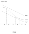
- FIG. 1 An embodiment of the invention is illustrated in combined Figures 1 and 2 , which show the simultaneous shifting of measurement frequencies, flow rate changes, and estimated and budgeted remaining power source energy during five time intervals t0-t4 for a heat meter according to the invention.
- FIG. 1 With Figure 1 is shown an initial time interval t0, during which the heat meter measures the fluid flow rate and the energy flow rate at a low measurement frequency F1.
- the fluid flow rate is shown with the curve "Fluid”
- the energy flow rate is shown with the curve "Energy”.
- t0 no changes are observed with any of the fluid flow rate or the energy flow rate.
- a change in the fluid flow rate is measured with the heat meter.
- the change in the flow rate exceeds a predetermined change of the flow rate, and in response hereto the measurement frequency is shifted from F1 to a higher measurement frequency F2.
- the energy flow rate is unchanged compared to t0.
- the stabilized fluid and energy flow rates are maintained, and the measurement frequency is further shifted to the initial measurement frequency F1, i.e. the measurement frequency cycle according to the invention is completed.
- the curve "Estimate” shows the estimate of the remaining energy vs. time during the time intervals t0-t4.
- the slope of respective curve sections indicates the power source energy consumption rate, i.e. the power source energy consumption per time.
- the lowest measurement frequency F1 is applied, and the energy consumption rate is small.
- the high measurement frequency F2 is applied, and the energy consumption rate is high.
- the intermediate measurement frequency F3 is applied, and the energy consumption rate is higher than during t0 and t4, however, lower than during t1 and t2.
- the "Budget 1" curve is below the “Estimate” curve, i.e. the estimate of the remaining power source energy exceeds the budgeted remaining power source energy as represented by the "Budget 1" curve.
- the estimate exceeds the budgeted remaining energy at the onset of time interval t1, i.e. at the time of shifting from measurement frequency F1 to measurement frequency F2.
- the shift of measurement frequency from F1 to F2 at the onset of time interval t1 is allowed as the provisions of (b2) of the present invention are fulfilled, in terms of fluid flow rate change (see above) as well as in terms of remaining power source energy.
- the alternative curve "Budget 2" which represents an alternative budget of remaining energy vs. time, is above the “Estimate” curve, i.e. the estimate of the remaining power source energy does not exceed the budgeted remaining power source energy as represent by the "Budget 2" curve.
- the estimate does not exceed the budgeted remaining energy at the onset of time interval t1, and in such case the otherwise flow-rate-wise intended shift from measurement frequency F1 to measurement frequency F2 would have been aborted as it would not have been allowed energy-budget-wise.
- the slope of the "Estimate” curve during the time intervals t0 and t4 is lower than the slope of the "Budget” curves.
- the power source energy consumption rate as represented by the slope of the "Estimate” curve, is smaller than the budgeted power source energy consumption rate as calculated as a uniform power source energy consumption rate over the lifetime of the power source. Accordingly, the actual power source energy consumption rate is less than the budgeted power source energy consumption rate, i.e. during these time intervals power source energy is "saved” compared to the budgeted power source energy consumption, and the excess of remaining energy over the budget is increased.
- the estimate of the power source energy consumption rate is higher than the budgeted power source energy consumption rate, i.e. an excess of power source energy is consumed compared to the budgeted power source energy consumption.
- the excess of remaining energy over the budget is reduced.
- the estimate of the power source energy consumption rate coincides with the budgeted power source energy consumption rate, i.e. the actual power source energy consumption rate is equal to the budgeted power source energy consumption rate, and the excess remaining energy over the budget is neither increased nor reduced.
Landscapes
- Chemical & Material Sciences (AREA)
- Engineering & Computer Science (AREA)
- Combustion & Propulsion (AREA)
- Physics & Mathematics (AREA)
- General Physics & Mathematics (AREA)
- Measuring Volume Flow (AREA)
Priority Applications (4)
| Application Number | Priority Date | Filing Date | Title |
|---|---|---|---|
| EP16153054.8A EP3199931A1 (fr) | 2016-01-28 | 2016-01-28 | Compteur de consommation avec une unité de calcul de l'énergie d'une source de puissance |
| EP17153531.3A EP3199932B1 (fr) | 2016-01-28 | 2017-01-27 | Compteur de consommation avec fréquence de mesure adaptative |
| PL17153531T PL3199932T3 (pl) | 2016-01-28 | 2017-01-27 | Miernik zużycia z adaptacyjną częstotliwością pomiaru |
| DK17153531.3T DK3199932T3 (en) | 2016-01-28 | 2017-01-27 | CONSUMER METER WITH ADAPTIVE MEASUREMENT RATE |
Applications Claiming Priority (1)
| Application Number | Priority Date | Filing Date | Title |
|---|---|---|---|
| EP16153054.8A EP3199931A1 (fr) | 2016-01-28 | 2016-01-28 | Compteur de consommation avec une unité de calcul de l'énergie d'une source de puissance |
Publications (1)
| Publication Number | Publication Date |
|---|---|
| EP3199931A1 true EP3199931A1 (fr) | 2017-08-02 |
Family
ID=55237593
Family Applications (2)
| Application Number | Title | Priority Date | Filing Date |
|---|---|---|---|
| EP16153054.8A Withdrawn EP3199931A1 (fr) | 2016-01-28 | 2016-01-28 | Compteur de consommation avec une unité de calcul de l'énergie d'une source de puissance |
| EP17153531.3A Active EP3199932B1 (fr) | 2016-01-28 | 2017-01-27 | Compteur de consommation avec fréquence de mesure adaptative |
Family Applications After (1)
| Application Number | Title | Priority Date | Filing Date |
|---|---|---|---|
| EP17153531.3A Active EP3199932B1 (fr) | 2016-01-28 | 2017-01-27 | Compteur de consommation avec fréquence de mesure adaptative |
Country Status (3)
| Country | Link |
|---|---|
| EP (2) | EP3199931A1 (fr) |
| DK (1) | DK3199932T3 (fr) |
| PL (1) | PL3199932T3 (fr) |
Cited By (2)
| Publication number | Priority date | Publication date | Assignee | Title |
|---|---|---|---|---|
| CN110177005A (zh) * | 2018-02-21 | 2019-08-27 | 卡姆鲁普股份有限公司 | 公用设施分配网络分析 |
| US10900819B2 (en) | 2018-08-16 | 2021-01-26 | AXIOMA Metering, UAB | Ultrasonic flowmeter |
Families Citing this family (3)
| Publication number | Priority date | Publication date | Assignee | Title |
|---|---|---|---|---|
| DE102020200749A1 (de) | 2020-01-22 | 2021-07-22 | Landis + Gyr Gmbh | Energiezähler und Verfahren zur Erfassung einer Wärme- oder Kältemenge |
| CN112235079B (zh) * | 2020-10-15 | 2022-07-01 | 宁波三星医疗电气股份有限公司 | 一种电能表的通信速率协商调整方法 |
| DE102021129096A1 (de) | 2021-11-09 | 2023-05-11 | Diehl Metering Gmbh | Verfahren zum Betrieb eines Ultraschall-Fluidzählers sowie Ultraschall-Fluidzähler |
Citations (4)
| Publication number | Priority date | Publication date | Assignee | Title |
|---|---|---|---|---|
| EP0898152A1 (fr) * | 1997-08-18 | 1999-02-24 | Bernina Electronic AG | Procédé pour le réglage de la fréquence d'échantillonage d'un échantillonneur pour la détection de la vitesse de rotation et de la direction de rotation de la turbine d'un débitmètre et un débitmètre pour la mise en oeuvre de ce procédé |
| EP1278047A2 (fr) * | 2001-07-16 | 2003-01-22 | Abb Research Ltd. | Procédé d' échantillonage pour débitmètres |
| WO2005055017A2 (fr) * | 2003-12-01 | 2005-06-16 | Ems-Patent Ag | Procede et dispositif de reduction du consommateur de courant dans des appareils a accumulateurs |
| EP2072982B1 (fr) | 2007-12-19 | 2012-10-03 | QUNDIS GmbH | Procédé de fonctionnement d'un appareil de mesure de consommation, notamment un répartiteur de coûts de chauffage |
Family Cites Families (1)
| Publication number | Priority date | Publication date | Assignee | Title |
|---|---|---|---|---|
| CN201237539Y (zh) * | 2008-04-14 | 2009-05-13 | 河南新天科技有限公司 | 一种智能降耗节电的热量表 |
-
2016
- 2016-01-28 EP EP16153054.8A patent/EP3199931A1/fr not_active Withdrawn
-
2017
- 2017-01-27 DK DK17153531.3T patent/DK3199932T3/en active
- 2017-01-27 PL PL17153531T patent/PL3199932T3/pl unknown
- 2017-01-27 EP EP17153531.3A patent/EP3199932B1/fr active Active
Patent Citations (4)
| Publication number | Priority date | Publication date | Assignee | Title |
|---|---|---|---|---|
| EP0898152A1 (fr) * | 1997-08-18 | 1999-02-24 | Bernina Electronic AG | Procédé pour le réglage de la fréquence d'échantillonage d'un échantillonneur pour la détection de la vitesse de rotation et de la direction de rotation de la turbine d'un débitmètre et un débitmètre pour la mise en oeuvre de ce procédé |
| EP1278047A2 (fr) * | 2001-07-16 | 2003-01-22 | Abb Research Ltd. | Procédé d' échantillonage pour débitmètres |
| WO2005055017A2 (fr) * | 2003-12-01 | 2005-06-16 | Ems-Patent Ag | Procede et dispositif de reduction du consommateur de courant dans des appareils a accumulateurs |
| EP2072982B1 (fr) | 2007-12-19 | 2012-10-03 | QUNDIS GmbH | Procédé de fonctionnement d'un appareil de mesure de consommation, notamment un répartiteur de coûts de chauffage |
Cited By (3)
| Publication number | Priority date | Publication date | Assignee | Title |
|---|---|---|---|---|
| CN110177005A (zh) * | 2018-02-21 | 2019-08-27 | 卡姆鲁普股份有限公司 | 公用设施分配网络分析 |
| EP3531368A1 (fr) * | 2018-02-21 | 2019-08-28 | Kamstrup A/S | Analyse de réseau de distribution public |
| US10900819B2 (en) | 2018-08-16 | 2021-01-26 | AXIOMA Metering, UAB | Ultrasonic flowmeter |
Also Published As
| Publication number | Publication date |
|---|---|
| EP3199932A1 (fr) | 2017-08-02 |
| DK3199932T3 (en) | 2019-03-25 |
| EP3199932B1 (fr) | 2018-11-28 |
| PL3199932T3 (pl) | 2019-05-31 |
Similar Documents
| Publication | Publication Date | Title |
|---|---|---|
| EP3199931A1 (fr) | Compteur de consommation avec une unité de calcul de l'énergie d'une source de puissance | |
| US8396607B2 (en) | Grid responsive control device | |
| CN101627515B (zh) | 需求控制系统、需求控制器以及需求控制方法 | |
| KR101764612B1 (ko) | 전기기기, 전력 관리기, 그를 가지는 전력 관리 시스템 및 그 제어 방법 | |
| CN110513930A (zh) | 空气源热泵机组变频压缩机加减载控制方法 | |
| JP6011951B2 (ja) | エネルギー管理装置、エネルギー管理システム、エネルギー管理方法、プログラム | |
| WO2020188266A1 (fr) | Commande de système d'énergie | |
| JP7378921B2 (ja) | 二次電池管理システム、及びその二次電池管理方法並びに二次電池管理プログラム、二次電池システム | |
| US20230299589A1 (en) | Coordinated management of an aggregate to provide primary frequency control | |
| US9948096B2 (en) | Method for providing control power to stabilize an alternating current network, using an energy accumulator | |
| US10113766B2 (en) | Air-conditioning management device and air-conditioning system using the same | |
| EP2937962A1 (fr) | Dispositif et procédé de contrôle de l'offre et la demande | |
| US20210044109A1 (en) | Method, Device and Computer Program for Designing a Battery Storage | |
| CN119651725A (zh) | 基于多目标协同运行的储能系统控制方法 | |
| JP5940956B2 (ja) | 電力量監視装置 | |
| JP6796533B2 (ja) | デマンド制御システム | |
| CN112564188A (zh) | 一种新能源电站的调频控制系统 | |
| KR102912776B1 (ko) | 저전력 소비를 갖는 시스템에서 배터리의 충전 상태를 추정하기 위한 방법 및 그 추정 방법을 수행하기 위한 시스템 | |
| CN111929589B (zh) | 一次性电池电量值输出方法、装置、终端及存储介质 | |
| HK40112766A (zh) | 用於估算低功耗系统中的电池的充电状态的方法以及用於实施该估算方法的系统 | |
| JP2012145242A (ja) | プラント制御装置及び蒸気使用プラントの制御方法 | |
| JP2008275467A (ja) | 電子式電力量計 | |
| JP2020191691A (ja) | 需給制御システム、需給制御方法及びプログラム |
Legal Events
| Date | Code | Title | Description |
|---|---|---|---|
| PUAI | Public reference made under article 153(3) epc to a published international application that has entered the european phase |
Free format text: ORIGINAL CODE: 0009012 |
|
| AK | Designated contracting states |
Kind code of ref document: A1 Designated state(s): AL AT BE BG CH CY CZ DE DK EE ES FI FR GB GR HR HU IE IS IT LI LT LU LV MC MK MT NL NO PL PT RO RS SE SI SK SM TR |
|
| AX | Request for extension of the european patent |
Extension state: BA ME |
|
| 17P | Request for examination filed |
Effective date: 20180201 |
|
| RBV | Designated contracting states (corrected) |
Designated state(s): AL AT BE BG CH CY CZ DE DK EE ES FI FR GB GR HR HU IE IS IT LI LT LU LV MC MK MT NL NO PL PT RO RS SE SI SK SM TR |
|
| GRAP | Despatch of communication of intention to grant a patent |
Free format text: ORIGINAL CODE: EPIDOSNIGR1 |
|
| INTG | Intention to grant announced |
Effective date: 20181025 |
|
| STAA | Information on the status of an ep patent application or granted ep patent |
Free format text: STATUS: THE APPLICATION IS DEEMED TO BE WITHDRAWN |
|
| 18D | Application deemed to be withdrawn |
Effective date: 20190305 |