EP3531825B1 - Dichtung in einem zitzenreiniger und zitzenreiniger - Google Patents
Dichtung in einem zitzenreiniger und zitzenreiniger Download PDFInfo
- Publication number
- EP3531825B1 EP3531825B1 EP17794441.0A EP17794441A EP3531825B1 EP 3531825 B1 EP3531825 B1 EP 3531825B1 EP 17794441 A EP17794441 A EP 17794441A EP 3531825 B1 EP3531825 B1 EP 3531825B1
- Authority
- EP
- European Patent Office
- Prior art keywords
- teat
- cleaner
- seal
- cleaning
- cup
- Prior art date
- Legal status (The legal status is an assumption and is not a legal conclusion. Google has not performed a legal analysis and makes no representation as to the accuracy of the status listed.)
- Active
Links
Images




Classifications
-
- A—HUMAN NECESSITIES
- A01—AGRICULTURE; FORESTRY; ANIMAL HUSBANDRY; HUNTING; TRAPPING; FISHING
- A01J—MANUFACTURE OF DAIRY PRODUCTS
- A01J7/00—Accessories for milking machines or devices
- A01J7/04—Accessories for milking machines or devices for treatment of udders or teats, e.g. for cleaning
-
- A—HUMAN NECESSITIES
- A01—AGRICULTURE; FORESTRY; ANIMAL HUSBANDRY; HUNTING; TRAPPING; FISHING
- A01J—MANUFACTURE OF DAIRY PRODUCTS
- A01J5/00—Milking machines or devices
- A01J5/04—Milking machines or devices with pneumatic manipulation of teats
- A01J5/08—Teat-cups with two chambers
-
- A—HUMAN NECESSITIES
- A01—AGRICULTURE; FORESTRY; ANIMAL HUSBANDRY; HUNTING; TRAPPING; FISHING
- A01K—ANIMAL HUSBANDRY; AVICULTURE; APICULTURE; PISCICULTURE; FISHING; REARING OR BREEDING ANIMALS, NOT OTHERWISE PROVIDED FOR; NEW BREEDS OF ANIMALS
- A01K13/00—Devices for grooming or caring of animals, e.g. curry-combs; Fetlock rings; Tail-holders; Devices for preventing crib-biting; Washing devices; Protection against weather conditions or insects
- A01K13/001—Washing, cleaning, or drying devices
-
- F—MECHANICAL ENGINEERING; LIGHTING; HEATING; WEAPONS; BLASTING
- F16—ENGINEERING ELEMENTS AND UNITS; GENERAL MEASURES FOR PRODUCING AND MAINTAINING EFFECTIVE FUNCTIONING OF MACHINES OR INSTALLATIONS; THERMAL INSULATION IN GENERAL
- F16J—PISTONS; CYLINDERS; SEALINGS
- F16J15/00—Sealings
- F16J15/02—Sealings between relatively-stationary surfaces
- F16J15/06—Sealings between relatively-stationary surfaces with solid packing compressed between sealing surfaces
- F16J15/10—Sealings between relatively-stationary surfaces with solid packing compressed between sealing surfaces with non-metallic packing
- F16J15/104—Sealings between relatively-stationary surfaces with solid packing compressed between sealing surfaces with non-metallic packing characterised by structure
Definitions
- This document discloses a seal and a teat cleaning cup. More particularly, a seal and a teat cleaning cup are described, wherein the seal is configured to seal between parts of the teat cleaning cup.
- the teat cleaning cup described therein is mainly compounded by an inner tube comprising a plurality of nozzle holes for spraying liquid/ air on the teat, and an outer plastic sleeve enclosing the inner tube.
- Y-shaped channels Distributing liquid to the teats, from a cleaning liquid supply, is made via Y-shaped channels. These Y-shaped channels are complicated to manufacture and difficult to depurate during washing.
- Teats of the animals may sometimes be very dirty, as the animals (free range animals) may rest directly on the ground, which may be muddy and/ or comprise manure. It would for this reason be desired to further improve the efficiency of teat cleaning.
- a seal according to claim 1 for a teat cleaning cup for cleaning a teat of an udder is configured to seal between a teat cleaner forming a central cavity configured to enclose the teat, and a lower part.
- the lower part is removably attached to the teat cleaner, which lower part comprises at least one cleaning liquid valve connectable to a cleaning liquid supply, and a drainage means for draining used cleaning liquid from the teat cleaner.
- the seal comprises a first surface for facing the teat cleaner and a second surface for facing the lower part.
- the seal is also configured to distribute liquid from the cleaning liquid valve of the lower part into a set of channels in the teat cleaner, which set of channels are extending along a longitudinal direction of the teat cleaner to the central cavity, where the set of channels are connected via a set of apertures in an inner body of the teat cleaner to the central cavity.
- the seal forms at least one first set of apertures, of at least a first aperture and a second aperture extending through the seal from the first surface to the second surface; and wherein the seal forms at least one recess in the second surface, connecting the first aperture to the second aperture.
- a teat cleaning cup for cleaning a teat of an udder.
- the teat cleaning cup comprises a teat cleaner, a lower part and a seal, according to the first aspect.
- the teat cleaner comprises an inner body, forming a central cavity configured to enclose a teat of the udder.
- the inner body comprises an inner surface, facing the central cavity, an outer surface, and a set of apertures, extending from the outer surface to the inner surface.
- the teat cleaner also comprises an exterior part, enclosing the inner body.
- a set of channels are situated between the inner body and the exterior part, which set of channels extend along a longitudinal direction of the teat cleaner and connect to the set of apertures.
- the lower part is removably attached to the teat cleaner.
- the lower part comprises at least one cleaning liquid valve connectable to a cleaning liquid supply, and a drainage means for draining used cleaning liquid from the teat cleaner.
- the described aspects by reducing the number of parts comprised in the teat cleaning cup, e.g. by making the teat cleaner by injection moulding and thereby fuse the exterior part with the inner body, it becomes easier to assemble/ disassemble the teat cleaning cup, leading to reduced manufacturing costs and a more service friendly product.
- Embodiments of the invention described herein are defined as a seal and a teat cleaning cup comprising the seal, which may be put into practice in the embodiments described below. These embodiments may, however, be exemplified and realised in many different forms and are not to be limited to the examples set forth herein; rather, these illustrative examples of embodiments are provided so that this disclosure will be thorough and complete.
- Figure 1 Illustrates a scenario with an animal 100 comprised in a herd of animals for dairy farming.
- Animal may be any arbitrary type of animal 100 relates to milk production.
- a domesticated mammal such as e.g. cow, goat, sheep, camel, horse, dairy buffalo, donkey, yak, etc.
- the animal 100 typically has an udder 110, comprising a set of teats 120.
- the number of teats 120 on the udder 110 is different for different animals 100; for example, a sow has normally 16 teats, a cat has 8, a bear has 6, a cow has 4 while a horse, sheep, goat and human has 2, etc.
- the milk of the animal 100 may be extracted e.g. by a milking device, by automatic milking in a rotary milking parlour or by an automated robotic milking system, just to mention some few arbitrary examples.
- a problem appearing when milking the animal 100 is that the teats 120 may be dirty. If the dirt is allowed to enter the milking machine, the dirt may affect the quality of the milk. Also, germs and bacteria may be spread between animals 100 in a farm, which may affect the health of the herd.
- the teat cleaning cup 130 may operate e.g. in conjunction with, or as part of, a milking robot or an automated milking system in a dairy farm. The parts and functionality of the teat cleaning cup 130 are discussed and explained in Figures 2A-2D and Figures 3-4 .
- the teat cleaning cup 130 by two-step injection moulding. Firstly, as two previously separate parts are moulded, the possible gap between them (due to tolerance) is eliminated. Thereby dirt and bacteria have less options to gain a foothold.
- the moulding eliminates requirements of the complicated and expensive machining of the prior art parts, leading to reduced production costs.
- the moulding generates a more stable construction of the teat cleaning cup 130, leading to improved efficiency of the teat cleaning cup 130 since no flexing walls cause pressure loss.
- a seal is situated between a teat cleaner and a lower part of the teat cleaning cup 130, as Illustrated in Figure 4 and notably in Figure 5 .
- the seal besides sealing between said parts, also is configured to distribute liquid from the cleaning liquid valve of the lower part into a set of channels in the teat cleaner.
- Figure 2A illustrates an embodiment of the teat cleaning cup 130 substantially as previously described in Figure 1 .
- the teat cleaning cup 130 comprises a teat cleaner, which in turn comprises an inner body and an exterior part 220, enclosing the inner body.
- the teat cleaning cup 130 also comprises a lower part 230 which may be realisably fastened to the teat cleaner.
- the lower part 230 may comprise a first cleaning liquid valve 240 , a second cleaning liquid valve 260 in some embodiments, and a drainage means 250 for draining used cleaning liquid from the teat cleaning cup 130.
- the teat cleaning cup 130 also may comprise a teat cleaner cup collar 210,
- the teat cleaner cup collar 210 may be made of rubber, silicon or similar material.
- the teat cleaner cup collar 210 may be fixated to the opening of the teat cleaner.
- ⁇ vacuum supplying means e.g. in the form of a non-collapsible pipe may in one of its ends connected to the drainage means 250 in the base of the teat cleaning cup 130, and with the other end to a vacuum supply for supplying an under-pressure within the teat cleaning cup 130, so as to facilitate draining used cleaning liquid from the teat cleaning cup 130 but also to enable pre-milking of the animal 100.
- a collector waste tank may be arranged between the teat cleaning cup 130 and the vacuum supply, for collecting used cleaning liquid and extracted pre-milk (which typically is not used for human consumption).
- a milk detector may optionally be arranged between the teat cleaning cup 130 and the collector waste tank for detecting presence of milk in the cleaning liquid but also for possible examination of extracted pre-milk in some embodiments.
- progesterone level of the milk of the animal 100 may be measured, which measurement may be used for heat detection in some embodiments.
- a shut off valve may be arranged between the collector waste tank and the vacuum supply, and a drain valve may be provided at the bottom of the collector waste tank.
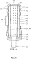
- FIG. 2B The interior of the teat cleaning cup 130 in a first cross section A-A is illustrated in Figure 2B and in a second cross section B-B in Figure 2C and Figure 2D .
- Figure 2B illustrates the cross section A-A of the teat cleaning cup 130 depicted in Figure 2A .
- the inner body 270 is forming a central cavity 280 configured to enclose a teat 120 of an udder 11 0.
- the inner body 270 comprises an inner surface 271, facing the central cavity 280 and an outer surface 272. Further, a set of apertures 275 in the inner body 270 are extending from the outer surface 272 of the inner body 270 to the inner surface 271 of the inner body 270.
- a set of channels 291, 292 are situated between the inner body 270 and the exterior part 220 of the teat cleaner.
- the set of channels 291, 292 are connected to the set of apertures 275, and also to the first cleaning liquid valve 240 and the second cleaning liquid valve 260. Thereby, cleaning liquid may be injected into the central cavity 280 of the Inner body 270 via the set of apertures 275, thereby spraying the teat 120 with the cleaning liquid.
- each channel 291, 292 may be connected to a plurality of apertures 275 for injecting cleaning liquid into the teat cleaning cup 130.
- a plurality of apertures 275 may be arranged substantially vertically in the teat cleaning cup 130 extending from a lowermost part of the teat cleaning cup 130 to an uppermost part of the teat cleaning cup 130.
- the whole length of the teat 120 is cleaned when injecting cleaning liquid through the apertures 275.
- the set of channels 291, 292, which typically are elongated and longitudinal with the teat cleaning cup 130, circumferentially separated from each other, may be of two distinct types, i.e. some channels 291, 292 may be configured for transportation of cleaning liquid and/or compressed air while some channels 291, 292 are intended for transportation of ambient air of standard atmosphere pressure.
- the channels of the first type may be configured connectable to any cleaning liquid valve 240, 260 while the channels of the second type are connected to ambient air via at least one aperture in the teat cleaner, thereby supplying said channels with air of standard atmosphere pressure.
- the set of channels 291, 292 may further be divided into different groups, such as e.g., two groups; e.g. a first channel subset 291 and a second channel subset 292.
- Each of the channel subsets 291, 292 may comprise at least one channel from the first type of channels and at least one channel from the second type of channels.
- the first channel subset 291 may be connected to the first cleaning liquid valve 240 while the second channel subset 292 may be connected to the second cleaning liquid valve 260. Further, the first channel subset 291 may advantageously be arranged on a first semi-circumferential side of the teat cleaning cup 130 while the second channel subset 292 may be arranged on the opposite semi-circumferential side of the teat cleaning cup 130.
- the teat 120 is deflecting from side to side when alternating the injection between the first channel subset 291 and the second channel subset 292. Consequently, hidden parts of the teat 120 is exposed for the injected cleaning liquid.
- said first and second groups of channels may be symmetrically arranged on the first and second semi-circumferential sides of the teat cleaning cup 130.
- a uniformly distributed cleaning intensity of the teat 120 is achieved.
- an enhanced cleaning action of the teat 120 and a pleasant animal experience is entertained.
- two channel subsets 291, 292 is merely a non-limiting example; a plurality of channel subsets of each type of channels separated circumferentially in the teat cleaning cup 130 are also conceivable in some embodiments.
- Each channel 291, 292 is connected to a number of apertures 275, separated circumferentially In the teat cleaner, connected to a respective channel 291, 292 of the teat cleaner.
- the previously discussed apertures 275 may be angled tangentially with the central cavity 280 of the Inner body 270, so as to allow injection of the cleaning liquid tangentially onto an inserted teat 120.
- dirt etc. may be rinsed from the teat 120, with minimal disturbance of the animal 100.
- the apertures 275 of the channels of the first type, for cleaning liquid transportation may be tangentially angled, while the apertures 275 of the channels of the second type, for ambient air transportation may have any arbitrary shape, as they are intended to allow ambient air to flow through the apertures 275 into the central cavity 280.
- the set of channels 291, 292 may be configured to repeatedly supply compressed-air into the teat cleaning cup 130, thereby stimulating the teat 120.
- the set of channels 291, 292 may be configured to repeatedly supply compressed-air into the teat cleaning cup 130, thereby stimulating the teat 120.
- the inner body 270 may comprise one or several exterior flanges 225, at least partly circumventing the exterior part 220.
- the teat cleaner cup collar 210 may comprise one or several recesses 212, corresponding to the exterior flanges 225 of the inner body 270. Thereby, the teat cleaner cup collar 210 may be fixated to the opening of the teat cleaner by fitting the recesses 212 of the teat cleaner cup collar 210 into the exterior flanges 225 of the inner body 270. Thereby, the teat cleaner cup collar 210 may be fixated to an upper part 221 of the teat cleaner.
- the teat cleaner cup collar 210 may in some embodiments comprise an edge 215 surrounding an opening of the teat cleaner cup collar 210, which opening is configured to enclose the teat 120, wherein the edge 215 is configured to physically remove dirt from the teat 120 when inserted into the central cavity 280 of the teat cleaning cup 130. Thereby, a mechanical cleaning of the teat 120 is introduced, as a complement to the liquid cleaning.
- the lower part 230 is removably attached to the teat cleaner, e.g. via a threaded insert, connectable to a respective fastening element for removably attaching the lower part 230 to the teat cleaner, in some embodiments.
- the seal 235 may seal between the lower part 230 and the teat cleaner.
- the seal 235 is depicted in Figures 4-5 , and further discussed in the corresponding text sequences.
- the teat cleaning cup 130 may in some embodiments comprise a handle 227, for simplifying handling of the teat cleaning cup 130, by a human and/ or a robot.
- Figure 2C illustrates the cross section B-B of the teat cleaning cup 130 depicted in Figure 2A .
- the previously discussed set of channels 291 are illustrated, in this case comprising a first subset of channels 291 and a second subset of channels 292.
- Figure 2D illustrates the cross section B-B of the teat cleaning cup 130 depicted in Figure 2A . It is actually the same cross section as illustrated in Figure 2C , but separate figures are provided for not crowding the image with references, allowing the references to obscure the Illustration.
- the central cavity 280 of the teat cleaning cup 130 is intended to circumvent the teat 120 of the animal 100.
- the central cavity 180 communicates with the drainage means 250, or outlet, for draining used cleaning liquid from the teat cleaning cup 130.
- vacuum or perhaps rather: air of an air pressure lower than the current ambient air pressure
- the drainage means 250 may be applied to the drainage means 250, for expanding the teat 120 and stretching the skin thereof.
- cracks dirt present on the teat 120 may be removed, as wrinkles in the teat skin are stretched out and a greater surface of the teat 120 is exposed to the injection cleaning.
- the vacuum may stimulate pre-milking of the teat 120.
- the teat cleaning cup 130 may comprise at least one cavity 299, wherein a thread insert may be inserted in some embodiments. Thereby, a releasable fastening of the lower part 230 of the teat cleaning cup 130 with the teat cleaner may be enabled.
- FIG 3 illustrates a teat cleaner 300, after having been moulded.
- the teat cleaner 300 may comprise a set of apertures 320 in the exterior part 220 of the teat cleaner 300 in some embodiments. These apertures are resulting from the manufacturing process, where a pin may be inserted for fixating a rod during a two-step moulding.
- the teat cleaner 300 comprises at least one aperture 310 in the teat cleaner 300, which aperture 310 connects channels 291, 292 of the second type of the channels, i.e. air channels, to ambient air via the respective aperture 310 in the teat cleaner 300.
- the teat cleaner 300 comprises an inner body 270, forming a central cavity 280 configured to enclose the teat 120 of the udder 110, wherein the inner body 270 comprises an inner surface 271, facing the central cavity 280.
- the inner body 270 also comprises an outer surface 272.
- a set of apertures 275 extend from the outer surface 272 to the inner surface 271 of the inner body 270.
- the teat cleaner 300 also comprises an exterior part 220, enclosing the inner body 270.
- the teat cleaner 300 furthermore comprises a set of channels 291, 292, situated between the inner body 270 and the exterior part 220, which set of channels 291, 292 extend along a longitudinal direction of the teat cleaner 300 and connect to the set of apertures 275.
- Figure 4 illustrates a teat cleaning cup 130 in an embodiment, illustrating the different parts of the teat cleaning cup 130 and how they may interact with each other.
- a teat cleaner cup collar 210 may be placed on the opening of the exterior part 220 of the teat cleaner 300, opposite to the drainage means 250.
- the teat cleaner cup collar 210 may be made in rubber, silicon or other similar elastic material.
- the teat cleaner cup collar 210 may seal against the teat 120 and/ or the udder 110 of the animal 100.
- the teat cleaner cup collar 210 may cover the opening of the teat cleaner 500, for covering a set of apertures 320 in the exterior part 220.
- a seal 235 is placed between the teat cleaner 300 and a lower part 230, removably attached to the teat cleaner 300.
- the lower part 230 which may be machine manufactured in some embodiments, may comprise a first cleaning liquid valve 240 and a second cleaning liquid valve 260 and a drainage means 250 for draining used cleaning liquid from the teat cleaning cup 130.
- the first cleaning liquid valve 240 may be attached to a first subset of channels 291 and the second cleaning liquid valve 260 may be attached to a second subset of channels 292, which channels all are of the second type of channels, i.e. liquid channels.
- the drainage means 250 may be attached to the central cavity 280.
- the seal 235 which may be manufactured of a polymer, polysulfide polymers, silicone rubber, polymercaptan, polyurethane, synthetic rubber, nitrile rubber or similar material, comprises a first surface 231 facing the teat cleaner 300 and a second surface 232 facing the lower part 230.
- the seal 235 is configured to distribute liquid from the cleaning liquid valve 240, 260 of the lower part 230 into the channels 291, 292 in the teat cleaner 300,
- the seal 235 forms at least one first set of apertures 401, 402, 403, 404, of at least a first aperture 401, 403 and a second aperture 402, 404, extending through the seal 235 from the first surface 231 to the second surface 232. Further, the seal 235 forms at least one recess 233, 234 in the second surface 232, connecting the first aperture 401, 403 to the second aperture 402, 404.
- the seal 235 forms the recess 233 of the first set of apertures 401, 402 receives liquid from the first cleaning liquid valve 240 and distribute the liquid via the first aperture 401 and the second aperture 402 to the first channel subset 291 in the teat cleaner 300; and the recess 234 of the second set of apertures 403, 404 receives liquid from the second cleaning liquid valve 260 and distribute the liquid via the first aperture 403 and the second aperture 404 to the second channel subset 292 in the teat cleaner 300 when the seal 235 is situated in a sealing position between the teat cleaner 300 and the lower part 230, during operation of the teat cleaning cup 130.
- the seal 235 may form an aperture 236 extending from the first surface 231 to the second surface 232 of the seal 235, configured for guiding used cleaning liquid from the teat cleaner 300 to the drainage means 250 of the lower part 230 when the seal 235 is situated in a sealing position between the teat cleaner 300 and the lower part 230, during operation of the teat cleaning cup 130.
- the lower part 230 may be removably attached to the teat cleaner 300 by at least one fastening element, such as threaded fastener, e.g. a screw, a bolt, etc.
- fastening element such as threaded fastener, e.g. a screw, a bolt, etc.
- fasteners e.g. a snap fastener, an R-clip pin, a split pin, a latch, a magnetic fastener, etc.
- the seal 235 may in at least some such embodiments form one fastening element aperture 237, 238 extending through the seal 235 from the first surface 231 to the second surface 232, for each fastening element.
- Figure 5 illustrates a seal 235 according to an embodiment.
- the second surface 232 of the seal 235 where the at least one recess 233, 234 is depicted connecting the first aperture 401, 403 to the second aperture 402, 404.
- the seal 235 may comprise at least one protrusion 501, 502, protruding from the first surface 231 and fitting into the teat cleaner 300, e.g. into one of the air channels or a recess in the teat cleaner 300. Thereby, it becomes easier to mount the seal 235 correctly, also during bad visibility conditions, or when changed by an inexperienced person.
- the term "and/ or” comprises any and all combinations of one or more of the associated listed items.
- the term "or” as used herein, is to be interpreted as a mathematical OR, i.e., as an inclusive disjunction; not as a mathematical exclusive OR (XOR), unless expressly stated otherwise.
Landscapes
- Life Sciences & Earth Sciences (AREA)
- Environmental Sciences (AREA)
- Animal Husbandry (AREA)
- Engineering & Computer Science (AREA)
- General Engineering & Computer Science (AREA)
- Animal Behavior & Ethology (AREA)
- Zoology (AREA)
- Biodiversity & Conservation Biology (AREA)
- Mechanical Engineering (AREA)
- Cleaning In General (AREA)
Claims (15)
- Abdichtung (235) für einen Zitzenreinigungsbecher (130) zum Reinigen einer Zitze (120) eines Euters (110), wobei die Abdichtung (235) konfiguriert ist, um zwischen Folgendem abzudichten:einem Zitzenreiniger (300), der einen mittleren Hohlraum (280) ausbildet, der konfiguriert ist, um die Zitze (120) einzuschließen, undeinem unteren Teil (230), der an dem Zitzenreiniger (300) entfernbar angebracht ist, wobei der untere Teil (230) wenigstens ein Reinigungsflüssigkeitsventil (240, 260), das mit einer Reinigungsflüssigkeitszufuhr verbindbar ist, und ein Ablassmittel (250) zum Ablassen verwendeter Reinigungsflüssigkeit aus dem Zitzenreiniger (300) umfasst;wobei die Abdichtung (235) eine erste Oberfläche (231) zum Gegenüberliegen des Zitzenreinigers (300) und eine zweite Oberfläche (232) zum Gegenüberliegen des unteren Teils (230) umfasst; undwobei die Abdichtung (235) konfiguriert ist, um Flüssigkeit von dem Reinigungsflüssigkeitsventil (240, 260) des unteren Teils (230) in eine Gruppe von Kanälen (291, 292) in dem Zitzenreiniger (300) zu verteilen, wobei die Gruppe von Kanälen (291, 292) sich entlang einer Längsrichtung des Zitzenreinigers (300) zu dem mittleren Hohlraum (280) erstreckt, wo die Gruppe von Kanälen (291, 292) mittels einer Gruppe von Öffnungen (275) in einem inneren Körper (270) des Zitzenreinigers (300) mit dem mittleren Hohlraum (280) verbunden ist; undwobei die Abdichtung (235) wenigstens eine erste Gruppe von Öffnungen (401, 402, 403, 404) von wenigstens einer ersten Öffnung (401, 403) und einer zweiten Öffnung (402, 404) ausbildet, die sich durch die Abdichtung (235) von der ersten Oberfläche (231) zu der zweiten Oberfläche (232) erstrecken;dadurch gekennzeichnet, dass die Abdichtung (235) wenigstens eine Aussparung (233, 234) in der zweiten Oberfläche (232) ausbildet, die die erste Öffnung (401, 403) mit der zweiten Öffnung (402, 404) verbindet.
- Abdichtung (235) nach Anspruch 1, wobei der untere Teil (230) ein erstes Reinigungsflüssigkeitsventil (240) und ein zweites Reinigungsflüssigkeitsventil (260) umfasst, die jeweils mit der Reinigungsflüssigkeitszufuhr verbindbar sind; und
wobei die Gruppe von Kanälen (291, 292) in dem Zitzenreiniger (300) eine erste Kanaluntergruppe (291) und eine zweite Kanaluntergruppe (292) umfasst; und
wobei die Abdichtung (235) Folgendes ausbildet:eine erste Gruppe von Öffnungen (401, 402) und eine zweite Gruppe von Öffnungen (403, 404),wobei jede Gruppe von Öffnungen (401, 402, 403, 404) die erste Öffnung (401, 403) und die zweite Öffnung (402, 404) und die Aussparung (233, 234) umfasst, die die erste Öffnung (401, 403) jeweils mit der zweiten Öffnung (402, 404) verbindet; und wobeidie Aussparung (233) der ersten Gruppe von Öffnungen (401, 402) Flüssigkeit von dem ersten Reinigungsflüssigkeitsventil (240) aufnimmt und die Flüssigkeit mittels der ersten Öffnung (401) und der zweiten Öffnung (402) auf die erste Kanaluntergruppe (291) in dem Zitzenreiniger (300) verteilt; unddie Aussparung (234) der zweiten Gruppe von Öffnungen (403, 404) Flüssigkeit von dem zweiten Reinigungsflüssigkeitsventil (260) aufnimmt und die Flüssigkeit mittels der ersten Öffnung (403) und der zweiten Öffnung (404) auf die zweite Kanaluntergruppe (292) in dem Zitzenreiniger (300) verteilt, wenn die Abdichtung (235) während eines Betriebs des Zitzenreinigungsbechers (130) in einer Abdichtungsposition zwischen dem Zitzenreiniger (300) und dem unteren Teil (230) gelegen ist. - Abdichtung (235) nach einem der Ansprüche 1-2, die wenigstens einen Vorsprung (501, 502) umfasst, der aus der ersten Oberfläche (231) vorspringt und in den Zitzenreiniger (300) passt.
- Abdichtung (235) nach einem der Ansprüche 1-3, die eine Öffnung (236) ausbildet, die sich von der ersten Oberfläche (231) zu der zweiten Oberfläche (232) der Abdichtung (235) erstreckt, die konfiguriert ist, um verwendete Reinigungsflüssigkeit von dem Zitzenreiniger (300) zu dem Ablassmittel (250) des unteren Teils (230) zu leiten, wenn die Abdichtung (235) während des Betriebs des Zitzenreinigers (130) in einer Abdichtungsposition zwischen dem Zitzenreiniger (300) und dem unteren Teil (230) gelegen ist.
- Abdichtung (235) nach einem der Ansprüche 1-4, wobei der untere Teil (230) durch wenigstens ein Befestigungselement an dem Zitzenreiniger (300) entfernbar angebracht ist, und
wobei die Abdichtung (235) für jedes Befestigungselement eine Befestigungselementöffnung (237, 238) ausbildet, die sich durch die Abdichtung (235) von der ersten Oberfläche (231) zu der zweiten Oberfläche (232) erstreckt. - Abdichtung (235) nach einem der Ansprüche 1-5, die aus einem Polymer hergestellt ist.
- Zitzenreinigungsbecher (130) zum Reinigen einer Zitze (120) eines Euters (110), wobei der Zitzenreinigungsbecher (130) Folgendes umfasst:einen Zitzenreiniger (300), der Folgendes umfasst:einen inneren Körper (270), der einen mittleren Hohlraum (280) ausbildet, der konfiguriert ist, um eine Zitze (120) eines Euters (110) einzuschließen, wobei der innere Körper (270) Folgendes umfasst:eine innere Oberfläche (271), die dem mittleren Hohlraum (280) gegenüberliegt,eine äußere Oberfläche (272), undwobei eine Gruppe von Öffnungen (275) sich von der äußeren Oberfläche (272) zu der inneren Oberfläche (271) erstreckt;einen Außenteil (220), der den inneren Körper (270) einschließt; undwobei eine Gruppe von Kanälen (291, 292) zwischen dem inneren Körper (270) und dem Außenteil (220) gelegen ist, wobei die Gruppe von Kanälen (291, 292) sich entlang einer Längsrichtung des Zitzenreinigers (300) erstreckt und mit der Gruppe von Öffnungen (275) verbindet;einen unteren Teil (230), der an dem Zitzenreiniger (300) entfernbar angebracht ist, wobei der untere Teil (230) Folgendes umfasst:wenigstens ein Reinigungsflüssigkeitsventil (240, 260), das mit einer Reinigungsflüssigkeitszufuhr verbindbar ist, undein Ablassmittel (250) zum Ablassen verwendeter Reinigungsflüssigkeit aus dem Zitzenreiniger (300); undeine Abdichtung (235) nach einem der Ansprüche 1-6.
- Zitzenreinigungsbecher (130) nach Anspruch 7, wobei eine erste Untergruppe der Gruppe von Kanälen (291, 292) mit einem beliebigen Reinigungsflüssigkeitsventil (240, 260) verbindbar ist, während eine zweite Untergruppe der Gruppe von Kanälen (291, 292) mit Umgebungsluft mittels wenigstens einer Öffnung (310) in dem Zitzenreiniger (300) verbunden ist, wobei dadurch der zweiten Untergruppe der Gruppe von Kanälen (291, 292) Luft mit Standardatmosphärendruck zugeführt wird.
- Zitzenreinigungsbecher (130) nach Anspruch 8, wobei wenigstens die Gruppe von Öffnungen (275), die mit der ersten Untergruppe der Gruppe von Kanälen (291, 292) verbunden ist, tangential zu dem mittleren Hohlraum (280) des inneren Körpers (270) abgewinkelt ist.
- Zitzenreinigungsbecher (130) nach einem der Ansprüche 7-9, wobei der Zitzenreiniger (300) wenigstens einen Gewindeeinsatz (237) umfasst, der mit einem jeweiligen Befestigungselement zum entfernbaren Anbringen des unteren Teils (230) an dem Zitzenreiniger (300) verbindbar ist.
- Zitzenreinigungsbecher (130) nach einem der Ansprüche 7-10, wobei der Zitzenreiniger (300) durch ein zweistufiges Spritzgießen erzeugt wird.
- Zitzenreinigungsbecher (130) nach einem der Ansprüche 7-11, der Folgendes umfasst:
eine Zitzenreinigerbechermanschette (210), die an einem oberen Teil (221) des Zitzenreinigers (300) gegenüber dem Ablassmittel (250) montiert ist. - Zitzenreinigungsbecher (130) nach Anspruch 12, wobei der obere Teil (221) des Zitzenreinigers (300) eine Gruppe von Außenflanschen (225) umfasst, die den Zitzenreiniger (300) wenigstens teilweise umgehen, und wobei die Zitzenreinigerbechermanschette (210) eine Gruppe von Aussparungen (212) umfasst, die konfiguriert sind, um in die Gruppe von Außenflanschen (225) des Zitzenreinigers (300) zum Fixieren der Zitzenreinigerbechermanschette (210) an dem oberen Teil (221) des Zitzenreinigers (300) zu passen.
- Zitzenreinigungsbecher (130) nach einem der Ansprüche 12 oder 13, der eine Kante (215) umfasst, die einen Durchlass der Zitzenreinigerbechermanschette (210) umgibt, wobei der Durchlass konfiguriert ist, um die Zitze (120) einzuschließen, wobei die Kante (215) konfiguriert ist, um Schmutz von der Zitze (120) physisch zu entfernen, wenn sie in den mittleren Hohlraum (280) des Zitzenreinigungsbechers (130) eingesetzt wird.
- Zitzenreinigungsbecher (130) nach einem der Ansprüche 7-14, der einen Griff (227) umfasst.
Applications Claiming Priority (2)
| Application Number | Priority Date | Filing Date | Title |
|---|---|---|---|
| SE1651406 | 2016-10-27 | ||
| PCT/SE2017/051037 WO2018080380A1 (en) | 2016-10-27 | 2017-10-23 | Seal in a teat cleaner and a teat cleaner |
Publications (2)
| Publication Number | Publication Date |
|---|---|
| EP3531825A1 EP3531825A1 (de) | 2019-09-04 |
| EP3531825B1 true EP3531825B1 (de) | 2021-05-19 |
Family
ID=60262977
Family Applications (1)
| Application Number | Title | Priority Date | Filing Date |
|---|---|---|---|
| EP17794441.0A Active EP3531825B1 (de) | 2016-10-27 | 2017-10-23 | Dichtung in einem zitzenreiniger und zitzenreiniger |
Country Status (3)
| Country | Link |
|---|---|
| US (1) | US11304399B2 (de) |
| EP (1) | EP3531825B1 (de) |
| WO (1) | WO2018080380A1 (de) |
Families Citing this family (3)
| Publication number | Priority date | Publication date | Assignee | Title |
|---|---|---|---|---|
| WO2021150111A1 (en) * | 2020-01-21 | 2021-07-29 | D.F. Van Staveren Holding B.V. | Spray head configured to clean teat of dairy animal |
| USD1017927S1 (en) | 2020-12-16 | 2024-03-12 | Jakob Maier Und Wilfried Hatzack Erfinder Gbr | Teat engagement structure |
| WO2023200926A1 (en) * | 2022-04-15 | 2023-10-19 | I B A, Inc. | Milking teatcup, teatcup shell, and inflation of a milking system |
Family Cites Families (14)
| Publication number | Priority date | Publication date | Assignee | Title |
|---|---|---|---|---|
| US2532088A (en) | 1947-11-01 | 1950-11-28 | Cordis Nat | Cleansing apparatus |
| US4305346A (en) * | 1980-09-26 | 1981-12-15 | Sparr Sr Anders V | Teat washing cup with milk let-down stimulating blades |
| US4530307A (en) * | 1982-10-06 | 1985-07-23 | Dec International, Inc. | Teat cup inflation |
| US5415130A (en) * | 1994-01-14 | 1995-05-16 | Brackett; Alan C. | Sprinkler for washing the udders of dairy animals |
| NL9500364A (nl) | 1995-02-24 | 1996-10-01 | Maasland Nv | Inrichting voor het melken van dieren. |
| SE512852C2 (sv) * | 1998-09-04 | 2000-05-22 | Alfa Laval Agri Ab | Spenkopp för mjölkning av kor eller andra djur |
| SE515440C2 (sv) * | 1999-09-09 | 2001-08-06 | Delaval Holding Ab | Förfarande och anordning för att tvätta spenar hos ett djur |
| US20020185071A1 (en) | 2001-06-08 | 2002-12-12 | Fangjiang Guo | Apparatus for cleaning a teat of a dairy animal |
| SE0103367D0 (sv) | 2001-10-10 | 2001-10-10 | Delaval Holding Ab | A device and a method for treatment of a teat of an animal |
| SE0201596D0 (sv) | 2002-05-29 | 2002-05-29 | Delaval Holding Ab | A device for cleaning the teats of an animal |
| US6935270B2 (en) | 2003-08-29 | 2005-08-30 | Delaval, Inc. | Milking and application teat cup, system, and method |
| NL1037240C2 (nl) * | 2009-08-31 | 2011-03-01 | Lely Patent Nv | Voorbehandelingsspeenbeker. |
| WO2012071000A1 (en) | 2010-11-22 | 2012-05-31 | Delaval Holding Ab | A teatcup liner and a teatcup |
| US20150334979A1 (en) | 2014-05-21 | 2015-11-26 | B&T Manufacturing LLC | Handheld brushless teat cleaning apparatus |
-
2017
- 2017-10-23 EP EP17794441.0A patent/EP3531825B1/de active Active
- 2017-10-23 US US16/322,393 patent/US11304399B2/en active Active
- 2017-10-23 WO PCT/SE2017/051037 patent/WO2018080380A1/en not_active Ceased
Also Published As
| Publication number | Publication date |
|---|---|
| US11304399B2 (en) | 2022-04-19 |
| US20190174708A1 (en) | 2019-06-13 |
| EP3531825A1 (de) | 2019-09-04 |
| WO2018080380A1 (en) | 2018-05-03 |
Similar Documents
| Publication | Publication Date | Title |
|---|---|---|
| EP3531825B1 (de) | Dichtung in einem zitzenreiniger und zitzenreiniger | |
| EP1933616B2 (de) | Zitzengummi | |
| EP1737292B1 (de) | Haltevorrichtung für melkbecher und aktuatorvorrichtung zum erzeugen einer bewegung eines melkgeschirrs | |
| WO2014016588A1 (en) | Milking cluster | |
| US10258016B2 (en) | Cleaning system and method for an automatic milking system | |
| CN205546839U (zh) | 一种挤奶机 | |
| US11147235B2 (en) | Cleaning unit for cleaning at least one head section of a teat cup | |
| US11246283B2 (en) | Two step moulding teat cleaner | |
| US10945406B2 (en) | Bovine teat washing and lactation stimulation device | |
| EP3410846B1 (de) | Zitzenvorbereitungssystem, -gummi und -verfahren | |
| US20180098519A1 (en) | Improvement to teat cup, milking head and milking operations | |
| US20110107971A1 (en) | Milking system, a teat cup and a teat cup liner | |
| CN209806790U (zh) | 奶牛养殖场用喷淋清洁装置 | |
| Marnet | Milking procedures and facilities | |
| US20150334979A1 (en) | Handheld brushless teat cleaning apparatus | |
| US20190008114A1 (en) | Teat dip application system | |
| CN211560523U (zh) | 可定位药浴的喷枪 | |
| US20100116212A1 (en) | Tube arrangement | |
| US2831456A (en) | Demountable milk receiver | |
| CA2411154A1 (en) | A device and a teat cup for milking animals | |
| UA151014U (uk) | Пристрій для обробки вимені корів у доїльних залах | |
| Kathiriya | Various procedures of machine milking | |
| RU124113U1 (ru) | Подвесная часть доильного аппарата для коз | |
| WO2025136187A1 (en) | Teatcup | |
| UA20435U (en) | Equipment to prepare cow udder to milking in stalls |
Legal Events
| Date | Code | Title | Description |
|---|---|---|---|
| STAA | Information on the status of an ep patent application or granted ep patent |
Free format text: STATUS: UNKNOWN |
|
| STAA | Information on the status of an ep patent application or granted ep patent |
Free format text: STATUS: THE INTERNATIONAL PUBLICATION HAS BEEN MADE |
|
| PUAI | Public reference made under article 153(3) epc to a published international application that has entered the european phase |
Free format text: ORIGINAL CODE: 0009012 |
|
| STAA | Information on the status of an ep patent application or granted ep patent |
Free format text: STATUS: REQUEST FOR EXAMINATION WAS MADE |
|
| 17P | Request for examination filed |
Effective date: 20190430 |
|
| AK | Designated contracting states |
Kind code of ref document: A1 Designated state(s): AL AT BE BG CH CY CZ DE DK EE ES FI FR GB GR HR HU IE IS IT LI LT LU LV MC MK MT NL NO PL PT RO RS SE SI SK SM TR |
|
| AX | Request for extension of the european patent |
Extension state: BA ME |
|
| DAV | Request for validation of the european patent (deleted) | ||
| DAX | Request for extension of the european patent (deleted) | ||
| REG | Reference to a national code |
Ref country code: DE Ref legal event code: R079 Ref document number: 602017038910 Country of ref document: DE Free format text: PREVIOUS MAIN CLASS: A01J0005080000 Ipc: A01K0013000000 |
|
| RIC1 | Information provided on ipc code assigned before grant |
Ipc: A01J 7/04 20060101ALI20201203BHEP Ipc: A01J 5/08 20060101ALI20201203BHEP Ipc: A01K 13/00 20060101AFI20201203BHEP |
|
| GRAP | Despatch of communication of intention to grant a patent |
Free format text: ORIGINAL CODE: EPIDOSNIGR1 |
|
| STAA | Information on the status of an ep patent application or granted ep patent |
Free format text: STATUS: GRANT OF PATENT IS INTENDED |
|
| INTG | Intention to grant announced |
Effective date: 20210112 |
|
| GRAS | Grant fee paid |
Free format text: ORIGINAL CODE: EPIDOSNIGR3 |
|
| GRAA | (expected) grant |
Free format text: ORIGINAL CODE: 0009210 |
|
| STAA | Information on the status of an ep patent application or granted ep patent |
Free format text: STATUS: THE PATENT HAS BEEN GRANTED |
|
| AK | Designated contracting states |
Kind code of ref document: B1 Designated state(s): AL AT BE BG CH CY CZ DE DK EE ES FI FR GB GR HR HU IE IS IT LI LT LU LV MC MK MT NL NO PL PT RO RS SE SI SK SM TR |
|
| REG | Reference to a national code |
Ref country code: GB Ref legal event code: FG4D |
|
| REG | Reference to a national code |
Ref country code: CH Ref legal event code: EP |
|
| REG | Reference to a national code |
Ref country code: DE Ref legal event code: R096 Ref document number: 602017038910 Country of ref document: DE |
|
| REG | Reference to a national code |
Ref country code: AT Ref legal event code: REF Ref document number: 1393104 Country of ref document: AT Kind code of ref document: T Effective date: 20210615 |
|
| REG | Reference to a national code |
Ref country code: NL Ref legal event code: FP Ref country code: IE Ref legal event code: FG4D |
|
| REG | Reference to a national code |
Ref country code: LT Ref legal event code: MG9D |
|
| REG | Reference to a national code |
Ref country code: AT Ref legal event code: MK05 Ref document number: 1393104 Country of ref document: AT Kind code of ref document: T Effective date: 20210519 |
|
| PG25 | Lapsed in a contracting state [announced via postgrant information from national office to epo] |
Ref country code: AT Free format text: LAPSE BECAUSE OF FAILURE TO SUBMIT A TRANSLATION OF THE DESCRIPTION OR TO PAY THE FEE WITHIN THE PRESCRIBED TIME-LIMIT Effective date: 20210519 Ref country code: BG Free format text: LAPSE BECAUSE OF FAILURE TO SUBMIT A TRANSLATION OF THE DESCRIPTION OR TO PAY THE FEE WITHIN THE PRESCRIBED TIME-LIMIT Effective date: 20210819 Ref country code: HR Free format text: LAPSE BECAUSE OF FAILURE TO SUBMIT A TRANSLATION OF THE DESCRIPTION OR TO PAY THE FEE WITHIN THE PRESCRIBED TIME-LIMIT Effective date: 20210519 Ref country code: FI Free format text: LAPSE BECAUSE OF FAILURE TO SUBMIT A TRANSLATION OF THE DESCRIPTION OR TO PAY THE FEE WITHIN THE PRESCRIBED TIME-LIMIT Effective date: 20210519 Ref country code: LT Free format text: LAPSE BECAUSE OF FAILURE TO SUBMIT A TRANSLATION OF THE DESCRIPTION OR TO PAY THE FEE WITHIN THE PRESCRIBED TIME-LIMIT Effective date: 20210519 |
|
| PG25 | Lapsed in a contracting state [announced via postgrant information from national office to epo] |
Ref country code: NO Free format text: LAPSE BECAUSE OF FAILURE TO SUBMIT A TRANSLATION OF THE DESCRIPTION OR TO PAY THE FEE WITHIN THE PRESCRIBED TIME-LIMIT Effective date: 20210819 Ref country code: PT Free format text: LAPSE BECAUSE OF FAILURE TO SUBMIT A TRANSLATION OF THE DESCRIPTION OR TO PAY THE FEE WITHIN THE PRESCRIBED TIME-LIMIT Effective date: 20210920 Ref country code: LV Free format text: LAPSE BECAUSE OF FAILURE TO SUBMIT A TRANSLATION OF THE DESCRIPTION OR TO PAY THE FEE WITHIN THE PRESCRIBED TIME-LIMIT Effective date: 20210519 Ref country code: PL Free format text: LAPSE BECAUSE OF FAILURE TO SUBMIT A TRANSLATION OF THE DESCRIPTION OR TO PAY THE FEE WITHIN THE PRESCRIBED TIME-LIMIT Effective date: 20210519 Ref country code: SE Free format text: LAPSE BECAUSE OF FAILURE TO SUBMIT A TRANSLATION OF THE DESCRIPTION OR TO PAY THE FEE WITHIN THE PRESCRIBED TIME-LIMIT Effective date: 20210519 Ref country code: RS Free format text: LAPSE BECAUSE OF FAILURE TO SUBMIT A TRANSLATION OF THE DESCRIPTION OR TO PAY THE FEE WITHIN THE PRESCRIBED TIME-LIMIT Effective date: 20210519 Ref country code: IS Free format text: LAPSE BECAUSE OF FAILURE TO SUBMIT A TRANSLATION OF THE DESCRIPTION OR TO PAY THE FEE WITHIN THE PRESCRIBED TIME-LIMIT Effective date: 20210919 Ref country code: GR Free format text: LAPSE BECAUSE OF FAILURE TO SUBMIT A TRANSLATION OF THE DESCRIPTION OR TO PAY THE FEE WITHIN THE PRESCRIBED TIME-LIMIT Effective date: 20210820 |
|
| PG25 | Lapsed in a contracting state [announced via postgrant information from national office to epo] |
Ref country code: SK Free format text: LAPSE BECAUSE OF FAILURE TO SUBMIT A TRANSLATION OF THE DESCRIPTION OR TO PAY THE FEE WITHIN THE PRESCRIBED TIME-LIMIT Effective date: 20210519 Ref country code: SM Free format text: LAPSE BECAUSE OF FAILURE TO SUBMIT A TRANSLATION OF THE DESCRIPTION OR TO PAY THE FEE WITHIN THE PRESCRIBED TIME-LIMIT Effective date: 20210519 Ref country code: ES Free format text: LAPSE BECAUSE OF FAILURE TO SUBMIT A TRANSLATION OF THE DESCRIPTION OR TO PAY THE FEE WITHIN THE PRESCRIBED TIME-LIMIT Effective date: 20210519 Ref country code: RO Free format text: LAPSE BECAUSE OF FAILURE TO SUBMIT A TRANSLATION OF THE DESCRIPTION OR TO PAY THE FEE WITHIN THE PRESCRIBED TIME-LIMIT Effective date: 20210519 Ref country code: DK Free format text: LAPSE BECAUSE OF FAILURE TO SUBMIT A TRANSLATION OF THE DESCRIPTION OR TO PAY THE FEE WITHIN THE PRESCRIBED TIME-LIMIT Effective date: 20210519 Ref country code: EE Free format text: LAPSE BECAUSE OF FAILURE TO SUBMIT A TRANSLATION OF THE DESCRIPTION OR TO PAY THE FEE WITHIN THE PRESCRIBED TIME-LIMIT Effective date: 20210519 Ref country code: CZ Free format text: LAPSE BECAUSE OF FAILURE TO SUBMIT A TRANSLATION OF THE DESCRIPTION OR TO PAY THE FEE WITHIN THE PRESCRIBED TIME-LIMIT Effective date: 20210519 |
|
| REG | Reference to a national code |
Ref country code: DE Ref legal event code: R097 Ref document number: 602017038910 Country of ref document: DE |
|
| PLBE | No opposition filed within time limit |
Free format text: ORIGINAL CODE: 0009261 |
|
| STAA | Information on the status of an ep patent application or granted ep patent |
Free format text: STATUS: NO OPPOSITION FILED WITHIN TIME LIMIT |
|
| 26N | No opposition filed |
Effective date: 20220222 |
|
| REG | Reference to a national code |
Ref country code: CH Ref legal event code: PL |
|
| PG25 | Lapsed in a contracting state [announced via postgrant information from national office to epo] |
Ref country code: IS Free format text: LAPSE BECAUSE OF FAILURE TO SUBMIT A TRANSLATION OF THE DESCRIPTION OR TO PAY THE FEE WITHIN THE PRESCRIBED TIME-LIMIT Effective date: 20210919 Ref country code: AL Free format text: LAPSE BECAUSE OF FAILURE TO SUBMIT A TRANSLATION OF THE DESCRIPTION OR TO PAY THE FEE WITHIN THE PRESCRIBED TIME-LIMIT Effective date: 20210519 |
|
| REG | Reference to a national code |
Ref country code: BE Ref legal event code: MM Effective date: 20211031 |
|
| PG25 | Lapsed in a contracting state [announced via postgrant information from national office to epo] |
Ref country code: MC Free format text: LAPSE BECAUSE OF FAILURE TO SUBMIT A TRANSLATION OF THE DESCRIPTION OR TO PAY THE FEE WITHIN THE PRESCRIBED TIME-LIMIT Effective date: 20210519 |
|
| PG25 | Lapsed in a contracting state [announced via postgrant information from national office to epo] |
Ref country code: LU Free format text: LAPSE BECAUSE OF NON-PAYMENT OF DUE FEES Effective date: 20211023 Ref country code: IT Free format text: LAPSE BECAUSE OF FAILURE TO SUBMIT A TRANSLATION OF THE DESCRIPTION OR TO PAY THE FEE WITHIN THE PRESCRIBED TIME-LIMIT Effective date: 20210519 Ref country code: BE Free format text: LAPSE BECAUSE OF NON-PAYMENT OF DUE FEES Effective date: 20211031 |
|
| PG25 | Lapsed in a contracting state [announced via postgrant information from national office to epo] |
Ref country code: LI Free format text: LAPSE BECAUSE OF NON-PAYMENT OF DUE FEES Effective date: 20211031 Ref country code: CH Free format text: LAPSE BECAUSE OF NON-PAYMENT OF DUE FEES Effective date: 20211031 |
|
| PG25 | Lapsed in a contracting state [announced via postgrant information from national office to epo] |
Ref country code: CY Free format text: LAPSE BECAUSE OF FAILURE TO SUBMIT A TRANSLATION OF THE DESCRIPTION OR TO PAY THE FEE WITHIN THE PRESCRIBED TIME-LIMIT Effective date: 20210519 |
|
| PG25 | Lapsed in a contracting state [announced via postgrant information from national office to epo] |
Ref country code: HU Free format text: LAPSE BECAUSE OF FAILURE TO SUBMIT A TRANSLATION OF THE DESCRIPTION OR TO PAY THE FEE WITHIN THE PRESCRIBED TIME-LIMIT; INVALID AB INITIO Effective date: 20171023 |
|
| PG25 | Lapsed in a contracting state [announced via postgrant information from national office to epo] |
Ref country code: MK Free format text: LAPSE BECAUSE OF FAILURE TO SUBMIT A TRANSLATION OF THE DESCRIPTION OR TO PAY THE FEE WITHIN THE PRESCRIBED TIME-LIMIT Effective date: 20210519 |
|
| PG25 | Lapsed in a contracting state [announced via postgrant information from national office to epo] |
Ref country code: MT Free format text: LAPSE BECAUSE OF FAILURE TO SUBMIT A TRANSLATION OF THE DESCRIPTION OR TO PAY THE FEE WITHIN THE PRESCRIBED TIME-LIMIT Effective date: 20210519 |
|
| PGFP | Annual fee paid to national office [announced via postgrant information from national office to epo] |
Ref country code: IE Payment date: 20240910 Year of fee payment: 8 |
|
| PGFP | Annual fee paid to national office [announced via postgrant information from national office to epo] |
Ref country code: GB Payment date: 20240906 Year of fee payment: 8 |
|
| PGFP | Annual fee paid to national office [announced via postgrant information from national office to epo] |
Ref country code: FR Payment date: 20240909 Year of fee payment: 8 |
|
| PGFP | Annual fee paid to national office [announced via postgrant information from national office to epo] |
Ref country code: NL Payment date: 20250912 Year of fee payment: 9 |
|
| PG25 | Lapsed in a contracting state [announced via postgrant information from national office to epo] |
Ref country code: TR Free format text: LAPSE BECAUSE OF FAILURE TO SUBMIT A TRANSLATION OF THE DESCRIPTION OR TO PAY THE FEE WITHIN THE PRESCRIBED TIME-LIMIT Effective date: 20210519 |
|
| PGFP | Annual fee paid to national office [announced via postgrant information from national office to epo] |
Ref country code: DE Payment date: 20250902 Year of fee payment: 9 |