EP3533367B1 - Construction en superstructure pour un d'écoulement des eaux à suspension symétrique de rabat de recouvrement - Google Patents
Construction en superstructure pour un d'écoulement des eaux à suspension symétrique de rabat de recouvrement Download PDFInfo
- Publication number
- EP3533367B1 EP3533367B1 EP19158809.4A EP19158809A EP3533367B1 EP 3533367 B1 EP3533367 B1 EP 3533367B1 EP 19158809 A EP19158809 A EP 19158809A EP 3533367 B1 EP3533367 B1 EP 3533367B1
- Authority
- EP
- European Patent Office
- Prior art keywords
- cover flap
- cover
- superstructure
- flap
- rotation
- Prior art date
- Legal status (The legal status is an assumption and is not a legal conclusion. Google has not performed a legal analysis and makes no representation as to the accuracy of the status listed.)
- Not-in-force
Links
Images



Classifications
-
- A—HUMAN NECESSITIES
- A47—FURNITURE; DOMESTIC ARTICLES OR APPLIANCES; COFFEE MILLS; SPICE MILLS; SUCTION CLEANERS IN GENERAL
- A47K—SANITARY EQUIPMENT; ACCESSORIES THEREFOR, e.g. TOILET ACCESSORIES
- A47K3/00—Baths; Showers; Appurtenances therefor
- A47K3/28—Showers or bathing douches
- A47K3/40—Pans or trays
- A47K3/405—Pans or trays flush with the surrounding floor, e.g. for easy access
-
- E—FIXED CONSTRUCTIONS
- E03—WATER SUPPLY; SEWERAGE
- E03F—SEWERS; CESSPOOLS
- E03F5/00—Sewerage structures
- E03F5/04—Gullies inlets, road sinks, floor drains with or without odour seals or sediment traps
- E03F5/0407—Floor drains for indoor use
- E03F5/0408—Floor drains for indoor use specially adapted for showers
Definitions
- a superstructure of the aforementioned type is from DE 10 2011 051 496 B4 known to the applicant.
- hanging hooks pointing towards the rear wall of the cover box are arranged, which protrude far beyond the visible surface of the cover flap, so they have a certain elasticity that can impair exact alignment.
- the mount point is behind the Center of gravity of the cover flap, so that the lower edge of the cover flap tends to be inclined to the rear, in which its visible surface is not aligned with the surrounding wall. The inclination can also contribute to undesirable dimensional differences and inaccuracies in the gap surrounding the cover flap.
- the cover flap can only be installed with a predetermined, for example metal, visible surface. If the cover flap is to have a second, "hidden", for example ceramic visible surface, the hooks must be unscrewed, turned around and reinstalled in order to reveal the ceramic visible surface instead of the metal one.
- the known superstructure construction has nevertheless proven itself, but there is a need to counteract the inclination of the installed cover flap to tilt and to facilitate the optional use of one of the two visible surfaces. It is therefore the object of the invention to design a new type of superstructure construction in which the inclined position of the cover flap that has previously occurred can be avoided with simple technical means. In addition, easy turning of the cover flap to the desired visible side should be guaranteed without having to use tools.
- the stop element, the load-bearing suspension element and the latching element lie in a center plane that is equidistant from the visible surfaces of the cover flap.
- the suspension element and / or the latching element are preferably mirror-symmetrical to this center plane, so that the position of the cover flap does not change when the cover flap is turned. Rather, only the visible surface of the cover flap changes in such a way that in a first installation position, for example, a stainless steel surface points outwards and a ceramic surface inwards, while in a second installation position, conversely, the stainless steel surface points inwards and the ceramic surface outwards.
- the suspension element which is preferably designed as a support bolt, together with a bearing arranged on the cover box, forms a stable suspension for the cover flap.
- the support bolt can be circular or oval or have the shape of a flattened cylinder, the rounded surface of which is supported on a trough-shaped or U-shaped mounting of the cover box when the cover flap is hung, so that a lowest point of the mounting defines an axis of rotation.
- the axis of rotation can be arranged coaxially with a central axis of the support bolt.
- the elements of the cover box cooperating with the aforementioned projecting elements of the cover flap are preferably arranged such that the suspended cover flap is vertically aligned and fixed in both installation positions and is flush with the surrounding wall.
- the installation position is to be understood as a vertically oriented position of the cover flap, in which a predetermined visible surface of the cover flap is selected. For example, a metallic visible surface can be brought to light in one installation position and a ceramic (tile) visible surface in another installation position.
- the stop element protruding over the narrow sides of the cover flap and the support bolt can be rigid or flexible.
- a stop surface is preferably provided on the cover box, with which the stop element of the cover flap makes contact when the cover flap is in a vertical position.
- the stop prevents the cover flap from rotating with its lower edge outwards.
- a rotational movement of the cover flap with its lower edge inwards, d. H. in an interior of the cover box is possible.
- cleaning work can be carried out in the drainage channel, for example.
- the holder is preferably designed in such a way that the cover flap can be lifted out of the holder or dismantled completely when required when the position is pivoted inward. Otherwise, due to the symmetrical structure, the cover flap will hang in its vertical position on the cover box. It is advantageous here that the two suspension elements (support bolts) lie above a center of gravity line of the cover flap.
- the cover plate can be provided on its narrow sides with latching and stop elements protruding in the direction of the side walls, which on the one hand enable the cover plate to rotate about an axis of rotation and on the other hand ensure its vertical, stable alignment so that the cover plate used with a surface of the wall element For example, tile covering can be in alignment.
- the latching elements protruding over the narrow sides of the cover plate can be rigid or flexible.
- the cover flap can on the one hand be held securely in a desired position and, on the other hand, if necessary, e.g. for cleaning the drainage channel located inside the superstructure element, can be easily dismantled.
- a rigid latching element can be formed, for example, by a rigid bolt protruding from the side surface of the cover flap.
- the latching function is implemented in this case in that the cover flap, which is rotatable about the axis of rotation of the suspension, has a bulge on the edge shortly before reaching its vertical end position contacted a recess. If the flap is rotated further, the bolt is guided along the bulge and the flap is raised a little. After overcoming the aforementioned bulge, the bolt engages in the recess behind the bulge due to gravity.
- a flexible design of a locking element can be implemented in that the locking bolt is supported in the direction of the narrow side against a spring element and is therefore linearly movable.
- a bore can be provided as a counter bearing in the side wall of the cover box or in a guide carriage.
- the suspension element and / or latching element and / or stop element can be integrated directly into the cover flap.
- the aforementioned functional elements can be worked out from the material of the cover flap by means of appropriate punching tools.
- an embodiment is particularly preferred in which the aforementioned functional parts of the suspension element, latching element and / or stop element are made from a molded piece, in particular from a plastic part.
- This shaped piece is designed so that it can be installed in the narrow side of the cover flap, preferably in a form-fitting manner.
- Such a design contributes to the fact that the protruding elements are matched with great accuracy to corresponding recesses on the narrow sides and, moreover, it facilitates the series production of the cover flaps.
- the side walls of the cover box each include a cuboid support body on which a trough or recess for guide elements of the suspension and a guide groove for receiving a nut arranged displaceably there, into which a preferably screw-like adjusting element is screwed.
- the cuboid support body can be made of metal or plastic, for example in the injection molding or 3D printing manufacturing process. With the help of the 3D printer, complex geometries can be created in one operation. Thermosets and thermoplastics can be used as plastics.
- the guide elements together with the support body and the setting element, form a clamping device for fixing the cover flap.
- the adjustability of the cover flap with respect to the cover box, the wall element and at the same time the floor area of the washing and shower area can be achieved by interlocking and displaceable guide elements. If the suspension is in a predetermined position, the guide elements and thus the suspension points are fixed. As a result, the cover flap can then be installed and removed as often as required and always assumes the same position when it is attached.
- the ends or narrow sides of the cover flap and its visible surfaces are preferably constructed with mirror symmetry to one another.
- the side walls of the cover box with their guide elements and adjustment elements are constructed mirror-symmetrically to one another. This enables the visible surface to be changed easily by folding over and reinserting the cover flap in the suspension of the side walls.
- FIG. 1 A shower area 50 is shown schematically in a separate representation in a ground-level version (without side walls), comprising a wall element 11 and a shower plate 49, which is provided at the factory with a channel 51 and drain installation elements (not shown) for a line drainage known per se.
- the wall element 11 ending in a cover box 16 and the shower tray 49 can be covered, for example, with ceramic or plastic coverings.
- the cover box 16 can have an overall width which is smaller than that of the wall element 11, so that it fits into a rectangular recess on the lower edge of the wall element 11. Another embodiment provides that the total width of the cover box 16 and the wall element 11 is the same.
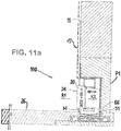
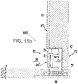
- the Figures 11a and 11b show a superstructure construction 100, comprising the cover box 16 built into the wall element 11 with a cover flap 20 suspended there.
- the superstructure construction 100 covers a schematically indicated drain 10 and at the same time the channel 51.
- the Fig. 1 a projection 52, shown with dashed lines, of the wall element 11 onto the shower tray 49 can be seen.
- the superstructure construction 100 makes it possible to dispense with the grate elements in the step area.
- the elements of the superstructure 100 are also shown in Figures 2a and 2b to see.
- the execution according to Figure 2a differs from the execution according to Figure 2b essentially through the structural design of the locking means with which the position of the cover flap is fixed in relation to the cover box.
- a flexible latching element 33 is provided, which latches into a receiving opening 36 in a predefined pivot position of the suspended cover flap 20 relative to the cover box 16.
- a rigid locking element 33 ' is provided in the form of a projection, which is also in a predefined pivot position the cover flap 20 is fixed in relation to the cover box 16. The fixation takes place in that the locking element 33 'snaps into the receiving opening 36'.
- Both cover boxes 16 are composed of a metal rear wall 17, a metal top wall 19 and two side walls 18, 18 'arranged mirror-symmetrically to one another.
- a cover box made entirely or partially from plastic, in particular injection molded plastic can also be provided.
- the cover box 16 has an underside 12 open towards the drain 10 (cf. Fig. 1 ) and a front side 13 open to the interior of the shower space 50 for receiving said cover flap 20 (cf. Figures 11a , 11b ) on.
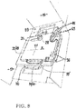
- the side wall 18, 18 ' is the Figures 5 to 9 refer to.
- the side wall 18, 18 ' comprises a solid support body 53 made of thermoplastic material, on the inside 69 of which there is a rectangular recess 39 and a guide groove 34 for receiving a nut 38 displaceably arranged there (cf. Fig. 9 ) is introduced.
- the guide groove 34 is approximately T-shaped in cross section.
- the recess 39 of the support body 53 is delimited by two guide edges 48, 48 'so that it forms a guide for a plate-shaped guide element 31 placed there and displaceable along the guide groove 34.
- the guide element 31 comprises two longitudinal edges 71, 71 'and two narrow edges 72, 72', the narrow edges 72, 72 'each via two U-shaped recesses 73, 73' made on the longitudinal edges 71, 71 'in two bent gripping arms 70, 70 'pass.
- the guide element 31 comprising the bore 29 and gripping arms 70, 70 ′ forms a first guide slide 41.
- the described guide element 32 functions as a second guide slide 42, the elongated hole 35 of which is directed perpendicular to the rear wall 17 of the cover box 16 in the assembled state of all guide elements.
- the offset arrangement of the elongated hole 35 with the guide groove 34 resembles a right-angled coordinate system (cf. Figures 6 and 8th ), in which "X” denotes a direction perpendicular to the rear wall 17 and "Y” denotes a direction perpendicular to the top wall 19.
- the interlocking guide elements 31; 32 (or guide carriage 41; 42) and the guide groove 34 ensure that the position of the suspended and aligned cover flap 20 can be adjusted and fixed by tightening the setting element 28 (head screw).
- the cover flap 20 is strip-shaped or cuboid (cf. Figures 2 and 3 ) and is mirror-symmetrical in relation to an in Figures 2a and 2b line of symmetry marked "S".
- the Figures 2a and 2b also shows a plate element 15 of the cover flap 20, having two longitudinal sides 22, 22 'and two narrow sides 23, 23'.
- the cover flap 20 is surrounded by a trough-shaped, metal frame 21.
- the trough-shaped structure enables an insert, for example in the form of natural stone or tiles, to be inserted into the interior of the trough.
- a metal frame 21 made of stainless steel, a first visible surface 24 formed by tiles or natural stone and a second visible surface 24 'formed from the rear of the metal frame 21 and opposite the first visible surface 24 (cf. Figure 11a ).
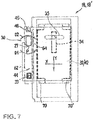
- the cover flap 20 has on its two narrow sides 23, 23 'elements protruding beyond the frame 21, namely the lower latching element 33 that can be snapped into a receiving opening 36 of the second guide carriage 42, an upper hanging element 64 (support bolt), which in turn is attached to the U-shaped bearing 65 is supported and is arranged to pivot about the axis of rotation 27 to a limited extent.
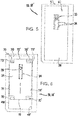
- the stop element 45 located above the upper latching element 64 also protrudes over the narrow side 23, 23 ′ and contacts the stop surface 46 when the cover flap 20 is aligned and thus limits the rotational movement of the cover flap 20 in direction D2.
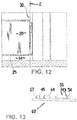
- the latching element 33, the stop element 45 and the suspension element 64 designed as a support bolt are integrated into a molded piece 62 which is in Fig. 13 is shown.
- the molded piece 62 is preferably made of plastic and is built into the narrow side 23, 23 'of the cover flap 20 in a form-fitting manner (cf. Fig. 4 ).
- the cover flap 20 is also constructed symmetrically with respect to a center plane M, so that the two visible surfaces 24 and 24 'in the same distance from the central plane M. This makes it easier to turn the cover flap 20 and to change the visible surface 24 or 24 '.
- the suspension element 64 protruding over the narrow side 23, 23 'of the cover flap 20, together with the U-shaped bearing 65, forms a suspension 30 (cf. Fig. 7 ), which according to Fig. 12 lie in the plane E running perpendicular to the rear wall 17 and / or top wall 19 of the cover box 16.
- the U-shaped bearing 65 is preferably rounded and adapted to the contour of the support bolt, which is preferably also rounded in the contact area. The at least approximately round support bolt contour can be rotated in the bearing 65 with little resistance.
- the cover flap 20 is oriented vertically with its ceramic visible surface 24, so that the first visible surface 24 points outward in the direction R1.
- the stop element 45 makes contact with the stop surface 46 of the second guide carriage 42 and prevents a direction of rotation D2 (cf. Fig. 7 ), so that the support bolt (suspension element 64) sits stably in the bearing 65. This corresponds to a first installation position P1 of the cover flap 20.
- the second visible surface 24 'facing inward in the direction R2 is "hidden" from the user in the installation position P1.
- a drain slot 14 is located between a lower edge 25 of the cover flap 20 and a floor surface 26 of the shower tray 49.
- the ceramic visible surface 24 is aligned with a ceramic surface 47 of the wall element 11.
- the cover flap 20 must first be removed. Since the side walls 18, 18 'are also constructed mirror-symmetrically to one another, changing the visible surfaces 24, 24' is very easy.
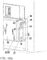
- the cover flap 20 is manually raised in the area of its lower edge 25, by a maximum of a small amount B (cf. Fig. 4 ) pressed. Since the lower, resilient latching element 33 has an inclined surface section 43 and a flexible projection 54, it yields during this movement, latches out of the receiving opening 36 and slides over an inner surface 44 of the guide carriage 42. Since the stop surface 46 rotates in the direction of rotation D1 allows, the cover flap 20 can be rotated about the axis of rotation 27 by a sufficient angular range. The lower edge 25 of the cover flap 20 pivots into an interior 66 of the cover box 20 and the cover flap 20 can be removed. Depending on the structural design of the latching and suspension elements, it may also be necessary that the rotary movement of the cover flap 20 is carried out in the first step and the cover flap 20 is then lifted out of the mounting in the second step.
- the removed cover flap 20 is now with its two ends 63, 63 '( Fig. 2, Fig. 2b ) and then reinserted until the lower latching element 33 with its flexible projection 54 - slides over the inner surface 44 of the guide carriage 42 - latches into the receiving opening 36 and the stop element 45 abuts against the stop surface 46.
- This position of the cover flap 20 corresponds to a second installation position P2 (cf. Figures 10a , 10b and 11b ). It should be pointed out that the rotation of the lower locking element 33 about the axis of rotation 27 when engaging and disengaging with a predefined torque D ( Figure 10b ) should take place.
- the suspension 30 must be shifted accordingly by loosening an adjusting element 28.
- a screw 37 is inserted through the elongated hole 35 of the second guide slide 42, the bore 29 of the first guide slide 41 and the guide groove 34 into the nut 38.
- the adjustment element 28 screw 37 with nut 38
- the adjustment element 28 is tightened until the guide carriage 41; 42 with the support body 53 a clamping connection 40 (cf. Fig. 9 ) train.
Landscapes
- Health & Medical Sciences (AREA)
- Public Health (AREA)
- Life Sciences & Earth Sciences (AREA)
- Engineering & Computer Science (AREA)
- Hydrology & Water Resources (AREA)
- Water Supply & Treatment (AREA)
- Epidemiology (AREA)
- General Health & Medical Sciences (AREA)
- Bathtubs, Showers, And Their Attachments (AREA)
- Finishing Walls (AREA)
Claims (11)
- Construction de superstructure (100 ; 100') d'un drain (10) qui est situé au niveau du sol d'un emplacement de lavage ou de douche et qui est ou doit être intégré dans un élément mural (11), la construction de superstructure comprenant :- un volet de recouvrement (20) en forme de plaque,- un boîtier de recouvrement (16) qui doit être placé sur le drain (10) et qui comprend une paroi arrière (17), une paroi de plafond (19) et des parois latérales (18, 18') reliant celles-ci, la boîte de recouvrement (16) comportant une face inférieure (12) ouverte en direction du drain (10) et une face avant (13) ouverte en direction de l'intérieur de l'emplacement de lavage ou de douche et destinée à recevoir le volet de recouvrement (20) en forme de plaque,- le volet de recouvrement (20) comportant une première et une deuxième surface visible (24 ; 24') dont l'une est dirigée, à l'état installé, dans la direction (R1) vers l'extérieur et l'autre dans la direction (R2) vers l'intérieur,- le volet de recouvrement (20) comportant un bord inférieur (25) et étant orienté, à l'état installé, à peu près perpendiculairement à une surface de sol (26) de l'emplacement de lavage ou de douche et étant disposé de telle manière qu'une fente de drainage (14) reste au-dessous du bord inférieur (25),- le volet de recouvrement (20) et le boîtier de recouvrement (16) étant accouplés l'un à l'autre de manière amovible par le biais d'une suspension (30) et le volet de recouvrement (20) étant mobile sur un axe de rotation (27),caractérisée en ce que- un élément d'encliquetage (33 ; 33') est disposé sur le volet de recouvrement (20) ou sur le boîtier de recouvrement (16) et permet de fixer le volet de recouvrement (20) dans une première position d'installation (P1) ou dans une deuxième position d'installation (P2), de préférence dans une orientation perpendiculaire,- l'axe de rotation (27) et un élément de suspension (64), pouvant tourner sur l'axe de rotation (27), ainsi que l'élément d'encliquetage (33 ; 33'), situé au-dessous de l'axe de rotation (27) lorsque le volet de recouvrement (20) est installé, sont chacun équidistants de la première surface visible (24) et de la deuxième surface visible (24') de sorte que, dans la première position d'installation (P1) du volet de recouvrement (20), la première surface visible (24) est orientée dans la direction (R1) et, dans la deuxième position d'installation (P2), la deuxième surface visible (24') est orientée dans la direction (R1).
- Construction de superstructure selon la revendication 1, caractérisée en ce que la position de l'axe de rotation (27) est définie par un point le plus bas (P) d'un palier (65) en forme de U, disposé sur le boîtier de recouvrement (16), de l'élément de suspension (64).
- Construction de superstructure selon la revendication 1 ou 2, caractérisée en ce que la suspension (30) comprend un élément de suspension (64), qui fait saillie sur un petit côté (23, 23') du volet de recouvrement (20), et un palier (65) destiné à l'élément de suspension (64).
- Construction de superstructure selon l'une des revendications 1 à 3, caractérisée en ce qu'un élément de butée (45) pourvu de surfaces de butée (67, 67') est disposé au-dessus de l'élément de suspension (64) du volet de recouvrement (20) et est équidistant de la première surface visible (24) et de la deuxième surface visible (24') et la surface de butée (67, 67') vient en contact, lorsque le volet de recouvrement (20) est orienté, avec une surface de butée (46) du boîtier de recouvrement (16) de sorte que le mouvement de rotation du volet de recouvrement (20) sur l'axe de rotation (27) soit limité.
- Construction de superstructure selon l'une des revendications 1 à 4, caractérisée en ce que le volet de recouvrement (20) comporte un plan central (M) et l'élément de suspension (64) et/ou l'élément d'encliquetage (33 ; 33') et/ou l'élément de butée (45) présente un contour à symétrie spéculaire par rapport au plan central (M).
- Construction de superstructure selon l'une des revendications 1 à 5, caractérisée en ce que l'élément de suspension (64) est disposé au niveau du volet de recouvrement (20) et le palier (65) est disposé au niveau du boîtier de recouvrement (16).
- Construction de superstructure selon l'une des revendications 1 à 6, caractérisée en ce que l'élément d'encliquetage (33) comprend une saillie flexible (43) qui s'engage dans une ouverture de réception (36) lorsque le volet de recouvrement (20) est en rotation sur l'axe de rotation (27).
- Construction de superstructure selon l'une des revendications 1 à 6, caractérisée en ce que l'élément d'encliquetage (33') comprend une saillie rigide qui s'engage dans une ouverture de réception (36') lorsque le volet de recouvrement (20) est en rotation sur l'axe de rotation (27).
- Construction de superstructure selon l'une des revendications 1 à 8, caractérisée en ce que l'élément d'encliquetage (33 ; 33') s'engage et/ou se désengage pour un couple prédéfini (D) sur l'axe de rotation (27).
- Construction de superstructure selon l'une des revendications 1 à 9, caractérisée en ce que l'élément de suspension (64), l'élément d'encliquetage (33 ; 33') et l'élément de butée (45) du volet de recouvrement (20) sont des parties d'une pièce moulée (62) qui est intégrée, de préférence par complémentarité de formes, dans le petit côté étroit (23, 23').
- Construction de superstructure selon l'une des revendications 1 à 10, caractérisée en ce que- des éléments de guidage (31 ; 32) compatibles entre eux sont prévus sur les parois latérales (18, 18') du boîtier de recouvrement (16) ou sur les petits côtés (23, 23') du volet de recouvrement (20) et sont disposés chacun dans un plan (E) perpendiculaire à la paroi arrière (17) ou à la paroi de plafond (19) et peuvent être fixés au boîtier de recouvrement (16) ou au volet de recouvrement (20) au moyen d'un élément de réglage (28),- la suspension (30) est déplaçable par le biais d'un premier élément de guidage (31) dans une direction (Y) perpendiculaire à la paroi de plafond (19) et par le biais d'un deuxième élément de guidage (32) dans une direction (X) perpendiculaire à la paroi arrière (17),de sorte que la position du volet de recouvrement (20) par rapport au boîtier de recouvrement (16) puisse être prédéfinie à la fois en termes de distance à la paroi de plafond (19) et en termes de distance à la paroi arrière (17) et puisse être fixée à l'aide de l'élément de réglage (28).
Applications Claiming Priority (1)
| Application Number | Priority Date | Filing Date | Title |
|---|---|---|---|
| DE102018104794.0A DE102018104794A1 (de) | 2018-03-02 | 2018-03-02 | Überbaukonstruktion für einen Wasserablauf mit symmetrischer Abdeckklappen-Aufhängung |
Publications (2)
| Publication Number | Publication Date |
|---|---|
| EP3533367A1 EP3533367A1 (fr) | 2019-09-04 |
| EP3533367B1 true EP3533367B1 (fr) | 2020-12-16 |
Family
ID=65529521
Family Applications (1)
| Application Number | Title | Priority Date | Filing Date |
|---|---|---|---|
| EP19158809.4A Not-in-force EP3533367B1 (fr) | 2018-03-02 | 2019-02-22 | Construction en superstructure pour un d'écoulement des eaux à suspension symétrique de rabat de recouvrement |
Country Status (2)
| Country | Link |
|---|---|
| EP (1) | EP3533367B1 (fr) |
| DE (1) | DE102018104794A1 (fr) |
Family Cites Families (5)
| Publication number | Priority date | Publication date | Assignee | Title |
|---|---|---|---|---|
| FR2916458B1 (fr) * | 2007-05-25 | 2009-08-07 | Constru Sa | Bouche d'egout avec un puits equipe d'un porte-filtre et d'un filtre amovible |
| DE202011002821U1 (de) * | 2011-02-16 | 2012-02-23 | Mepa - Pauli Und Menden Gmbh | Duschwanne mit integriertem Wandablauf |
| DE102011051496B4 (de) | 2011-07-01 | 2013-04-04 | Stephan Wedi | Überbausystem für einen im Bodenbereich befindlichen Ablauf |
| DK2818600T3 (en) * | 2013-06-26 | 2017-07-24 | Geberit Int Ag | Floor drain with adjustable cover |
| DE202014004016U1 (de) * | 2014-05-12 | 2014-08-14 | Frank Huster | Revisionsklappe mit magnetischer Positionierungshilfe |
-
2018
- 2018-03-02 DE DE102018104794.0A patent/DE102018104794A1/de not_active Ceased
-
2019
- 2019-02-22 EP EP19158809.4A patent/EP3533367B1/fr not_active Not-in-force
Also Published As
| Publication number | Publication date |
|---|---|
| DE102018104794A1 (de) | 2019-09-05 |
| EP3533367A1 (fr) | 2019-09-04 |
Similar Documents
| Publication | Publication Date | Title |
|---|---|---|
| DE2911094A1 (de) | Plattenverbindungssystem | |
| EP2808457A2 (fr) | Dispositif d'écoulement d'eau pour une installation sanitaire, ainsi que douche à l'italienne | |
| EP3034730B1 (fr) | Charnière dotée d'un mécanisme de levage/d'abaissement | |
| EP2540922A2 (fr) | Système de superstructure pour un écoulement se trouvant dans la zone au sol | |
| EP3486420B1 (fr) | Procédé de positionnement d'une fenêtre ou d'une porte | |
| DE102007057382B4 (de) | Nivellierfuß | |
| WO2022063560A1 (fr) | Élément de meuble et meuble | |
| EP0495205B1 (fr) | Ecran pour douche avec porte articulée | |
| EP2618706B1 (fr) | Paroi de douche équipée d'une porte coulissante | |
| DE2253600A1 (de) | Stange zum einfuehren von vorhangtraegern | |
| EP3167988B1 (fr) | Scie à guichet | |
| DE112015002884B4 (de) | Schublade | |
| EP3533367B1 (fr) | Construction en superstructure pour un d'écoulement des eaux à suspension symétrique de rabat de recouvrement | |
| AT519907B1 (de) | Möbelscharnier | |
| EP3890555B1 (fr) | Composant de meuble | |
| EP3533944B1 (fr) | Construction de superstructure pour une évacuation d'eau à suspension du rabat de recouvrement réglable | |
| EP2880226B1 (fr) | Système de profilé de sol basculant | |
| DE19937892C1 (de) | Befestigungsvorrichtung | |
| EP0445363A1 (fr) | Dispositif de fraisage ou perçage | |
| DE10118223C2 (de) | Klemmbeschlag für Duschabtrennungen | |
| DE19828233A1 (de) | Wandkonsole | |
| EP2818600B1 (fr) | Bouche d'égout comprenant un couvercle ajustable | |
| WO1997048087A1 (fr) | Support pour panneaux pivotants ou similaire | |
| EP0602378A1 (fr) | Dispositif de montage pour hottes d'évacuation defumées encastrées ou annexes à des éléments d'armoire suspendue | |
| EP4085797B1 (fr) | Dispositif de suspension ajustable |
Legal Events
| Date | Code | Title | Description |
|---|---|---|---|
| PUAI | Public reference made under article 153(3) epc to a published international application that has entered the european phase |
Free format text: ORIGINAL CODE: 0009012 |
|
| STAA | Information on the status of an ep patent application or granted ep patent |
Free format text: STATUS: THE APPLICATION HAS BEEN PUBLISHED |
|
| AK | Designated contracting states |
Kind code of ref document: A1 Designated state(s): AL AT BE BG CH CY CZ DE DK EE ES FI FR GB GR HR HU IE IS IT LI LT LU LV MC MK MT NL NO PL PT RO RS SE SI SK SM TR |
|
| AX | Request for extension of the european patent |
Extension state: BA ME |
|
| STAA | Information on the status of an ep patent application or granted ep patent |
Free format text: STATUS: REQUEST FOR EXAMINATION WAS MADE |
|
| 17P | Request for examination filed |
Effective date: 20200225 |
|
| RBV | Designated contracting states (corrected) |
Designated state(s): AL AT BE BG CH CY CZ DE DK EE ES FI FR GB GR HR HU IE IS IT LI LT LU LV MC MK MT NL NO PL PT RO RS SE SI SK SM TR |
|
| GRAP | Despatch of communication of intention to grant a patent |
Free format text: ORIGINAL CODE: EPIDOSNIGR1 |
|
| STAA | Information on the status of an ep patent application or granted ep patent |
Free format text: STATUS: GRANT OF PATENT IS INTENDED |
|
| RIC1 | Information provided on ipc code assigned before grant |
Ipc: A47K 3/40 20060101AFI20200713BHEP Ipc: E03F 5/04 20060101ALI20200713BHEP |
|
| INTG | Intention to grant announced |
Effective date: 20200729 |
|
| GRAS | Grant fee paid |
Free format text: ORIGINAL CODE: EPIDOSNIGR3 |
|
| GRAA | (expected) grant |
Free format text: ORIGINAL CODE: 0009210 |
|
| STAA | Information on the status of an ep patent application or granted ep patent |
Free format text: STATUS: THE PATENT HAS BEEN GRANTED |
|
| AK | Designated contracting states |
Kind code of ref document: B1 Designated state(s): AL AT BE BG CH CY CZ DE DK EE ES FI FR GB GR HR HU IE IS IT LI LT LU LV MC MK MT NL NO PL PT RO RS SE SI SK SM TR |
|
| REG | Reference to a national code |
Ref country code: GB Ref legal event code: FG4D Free format text: NOT ENGLISH |
|
| REG | Reference to a national code |
Ref country code: IE Ref legal event code: FG4D Free format text: LANGUAGE OF EP DOCUMENT: GERMAN |
|
| REG | Reference to a national code |
Ref country code: DE Ref legal event code: R096 Ref document number: 502019000518 Country of ref document: DE |
|
| REG | Reference to a national code |
Ref country code: AT Ref legal event code: REF Ref document number: 1344800 Country of ref document: AT Kind code of ref document: T Effective date: 20210115 |
|
| REG | Reference to a national code |
Ref country code: NL Ref legal event code: FP |
|
| PG25 | Lapsed in a contracting state [announced via postgrant information from national office to epo] |
Ref country code: FI Free format text: LAPSE BECAUSE OF FAILURE TO SUBMIT A TRANSLATION OF THE DESCRIPTION OR TO PAY THE FEE WITHIN THE PRESCRIBED TIME-LIMIT Effective date: 20201216 Ref country code: RS Free format text: LAPSE BECAUSE OF FAILURE TO SUBMIT A TRANSLATION OF THE DESCRIPTION OR TO PAY THE FEE WITHIN THE PRESCRIBED TIME-LIMIT Effective date: 20201216 Ref country code: NO Free format text: LAPSE BECAUSE OF FAILURE TO SUBMIT A TRANSLATION OF THE DESCRIPTION OR TO PAY THE FEE WITHIN THE PRESCRIBED TIME-LIMIT Effective date: 20210316 Ref country code: GR Free format text: LAPSE BECAUSE OF FAILURE TO SUBMIT A TRANSLATION OF THE DESCRIPTION OR TO PAY THE FEE WITHIN THE PRESCRIBED TIME-LIMIT Effective date: 20210317 |
|
| PG25 | Lapsed in a contracting state [announced via postgrant information from national office to epo] |
Ref country code: LV Free format text: LAPSE BECAUSE OF FAILURE TO SUBMIT A TRANSLATION OF THE DESCRIPTION OR TO PAY THE FEE WITHIN THE PRESCRIBED TIME-LIMIT Effective date: 20201216 Ref country code: SE Free format text: LAPSE BECAUSE OF FAILURE TO SUBMIT A TRANSLATION OF THE DESCRIPTION OR TO PAY THE FEE WITHIN THE PRESCRIBED TIME-LIMIT Effective date: 20201216 Ref country code: BG Free format text: LAPSE BECAUSE OF FAILURE TO SUBMIT A TRANSLATION OF THE DESCRIPTION OR TO PAY THE FEE WITHIN THE PRESCRIBED TIME-LIMIT Effective date: 20210316 |
|
| PG25 | Lapsed in a contracting state [announced via postgrant information from national office to epo] |
Ref country code: HR Free format text: LAPSE BECAUSE OF FAILURE TO SUBMIT A TRANSLATION OF THE DESCRIPTION OR TO PAY THE FEE WITHIN THE PRESCRIBED TIME-LIMIT Effective date: 20201216 |
|
| REG | Reference to a national code |
Ref country code: LT Ref legal event code: MG9D |
|
| PG25 | Lapsed in a contracting state [announced via postgrant information from national office to epo] |
Ref country code: EE Free format text: LAPSE BECAUSE OF FAILURE TO SUBMIT A TRANSLATION OF THE DESCRIPTION OR TO PAY THE FEE WITHIN THE PRESCRIBED TIME-LIMIT Effective date: 20201216 Ref country code: SK Free format text: LAPSE BECAUSE OF FAILURE TO SUBMIT A TRANSLATION OF THE DESCRIPTION OR TO PAY THE FEE WITHIN THE PRESCRIBED TIME-LIMIT Effective date: 20201216 Ref country code: SM Free format text: LAPSE BECAUSE OF FAILURE TO SUBMIT A TRANSLATION OF THE DESCRIPTION OR TO PAY THE FEE WITHIN THE PRESCRIBED TIME-LIMIT Effective date: 20201216 Ref country code: CZ Free format text: LAPSE BECAUSE OF FAILURE TO SUBMIT A TRANSLATION OF THE DESCRIPTION OR TO PAY THE FEE WITHIN THE PRESCRIBED TIME-LIMIT Effective date: 20201216 Ref country code: LT Free format text: LAPSE BECAUSE OF FAILURE TO SUBMIT A TRANSLATION OF THE DESCRIPTION OR TO PAY THE FEE WITHIN THE PRESCRIBED TIME-LIMIT Effective date: 20201216 Ref country code: RO Free format text: LAPSE BECAUSE OF FAILURE TO SUBMIT A TRANSLATION OF THE DESCRIPTION OR TO PAY THE FEE WITHIN THE PRESCRIBED TIME-LIMIT Effective date: 20201216 Ref country code: PT Free format text: LAPSE BECAUSE OF FAILURE TO SUBMIT A TRANSLATION OF THE DESCRIPTION OR TO PAY THE FEE WITHIN THE PRESCRIBED TIME-LIMIT Effective date: 20210416 |
|
| PG25 | Lapsed in a contracting state [announced via postgrant information from national office to epo] |
Ref country code: PL Free format text: LAPSE BECAUSE OF FAILURE TO SUBMIT A TRANSLATION OF THE DESCRIPTION OR TO PAY THE FEE WITHIN THE PRESCRIBED TIME-LIMIT Effective date: 20201216 |
|
| REG | Reference to a national code |
Ref country code: DE Ref legal event code: R097 Ref document number: 502019000518 Country of ref document: DE |
|
| PG25 | Lapsed in a contracting state [announced via postgrant information from national office to epo] |
Ref country code: MC Free format text: LAPSE BECAUSE OF FAILURE TO SUBMIT A TRANSLATION OF THE DESCRIPTION OR TO PAY THE FEE WITHIN THE PRESCRIBED TIME-LIMIT Effective date: 20201216 Ref country code: IS Free format text: LAPSE BECAUSE OF FAILURE TO SUBMIT A TRANSLATION OF THE DESCRIPTION OR TO PAY THE FEE WITHIN THE PRESCRIBED TIME-LIMIT Effective date: 20210416 |
|
| PLBE | No opposition filed within time limit |
Free format text: ORIGINAL CODE: 0009261 |
|
| STAA | Information on the status of an ep patent application or granted ep patent |
Free format text: STATUS: NO OPPOSITION FILED WITHIN TIME LIMIT |
|
| REG | Reference to a national code |
Ref country code: BE Ref legal event code: MM Effective date: 20210228 |
|
| PG25 | Lapsed in a contracting state [announced via postgrant information from national office to epo] |
Ref country code: LU Free format text: LAPSE BECAUSE OF NON-PAYMENT OF DUE FEES Effective date: 20210222 Ref country code: AL Free format text: LAPSE BECAUSE OF FAILURE TO SUBMIT A TRANSLATION OF THE DESCRIPTION OR TO PAY THE FEE WITHIN THE PRESCRIBED TIME-LIMIT Effective date: 20201216 |
|
| 26N | No opposition filed |
Effective date: 20210917 |
|
| PG25 | Lapsed in a contracting state [announced via postgrant information from national office to epo] |
Ref country code: DK Free format text: LAPSE BECAUSE OF FAILURE TO SUBMIT A TRANSLATION OF THE DESCRIPTION OR TO PAY THE FEE WITHIN THE PRESCRIBED TIME-LIMIT Effective date: 20201216 |
|
| PG25 | Lapsed in a contracting state [announced via postgrant information from national office to epo] |
Ref country code: IE Free format text: LAPSE BECAUSE OF NON-PAYMENT OF DUE FEES Effective date: 20210222 Ref country code: ES Free format text: LAPSE BECAUSE OF FAILURE TO SUBMIT A TRANSLATION OF THE DESCRIPTION OR TO PAY THE FEE WITHIN THE PRESCRIBED TIME-LIMIT Effective date: 20201216 |
|
| PG25 | Lapsed in a contracting state [announced via postgrant information from national office to epo] |
Ref country code: SI Free format text: LAPSE BECAUSE OF FAILURE TO SUBMIT A TRANSLATION OF THE DESCRIPTION OR TO PAY THE FEE WITHIN THE PRESCRIBED TIME-LIMIT Effective date: 20201216 |
|
| PGFP | Annual fee paid to national office [announced via postgrant information from national office to epo] |
Ref country code: DE Payment date: 20220224 Year of fee payment: 4 |
|
| PG25 | Lapsed in a contracting state [announced via postgrant information from national office to epo] |
Ref country code: IS Free format text: LAPSE BECAUSE OF FAILURE TO SUBMIT A TRANSLATION OF THE DESCRIPTION OR TO PAY THE FEE WITHIN THE PRESCRIBED TIME-LIMIT Effective date: 20210416 |
|
| PGFP | Annual fee paid to national office [announced via postgrant information from national office to epo] |
Ref country code: NL Payment date: 20220118 Year of fee payment: 4 Ref country code: IT Payment date: 20220228 Year of fee payment: 4 Ref country code: FR Payment date: 20220118 Year of fee payment: 4 |
|
| PG25 | Lapsed in a contracting state [announced via postgrant information from national office to epo] |
Ref country code: BE Free format text: LAPSE BECAUSE OF NON-PAYMENT OF DUE FEES Effective date: 20210228 |
|
| REG | Reference to a national code |
Ref country code: CH Ref legal event code: PL |
|
| PG25 | Lapsed in a contracting state [announced via postgrant information from national office to epo] |
Ref country code: LI Free format text: LAPSE BECAUSE OF NON-PAYMENT OF DUE FEES Effective date: 20220228 Ref country code: CH Free format text: LAPSE BECAUSE OF NON-PAYMENT OF DUE FEES Effective date: 20220228 |
|
| PG25 | Lapsed in a contracting state [announced via postgrant information from national office to epo] |
Ref country code: CY Free format text: LAPSE BECAUSE OF FAILURE TO SUBMIT A TRANSLATION OF THE DESCRIPTION OR TO PAY THE FEE WITHIN THE PRESCRIBED TIME-LIMIT Effective date: 20201216 |
|
| PG25 | Lapsed in a contracting state [announced via postgrant information from national office to epo] |
Ref country code: HU Free format text: LAPSE BECAUSE OF FAILURE TO SUBMIT A TRANSLATION OF THE DESCRIPTION OR TO PAY THE FEE WITHIN THE PRESCRIBED TIME-LIMIT; INVALID AB INITIO Effective date: 20190222 |
|
| REG | Reference to a national code |
Ref country code: DE Ref legal event code: R119 Ref document number: 502019000518 Country of ref document: DE |
|
| REG | Reference to a national code |
Ref country code: NL Ref legal event code: MM Effective date: 20230301 |
|
| GBPC | Gb: european patent ceased through non-payment of renewal fee |
Effective date: 20230222 |
|
| PG25 | Lapsed in a contracting state [announced via postgrant information from national office to epo] |
Ref country code: NL Free format text: LAPSE BECAUSE OF NON-PAYMENT OF DUE FEES Effective date: 20230301 |
|
| PG25 | Lapsed in a contracting state [announced via postgrant information from national office to epo] |
Ref country code: GB Free format text: LAPSE BECAUSE OF NON-PAYMENT OF DUE FEES Effective date: 20230222 |
|
| PG25 | Lapsed in a contracting state [announced via postgrant information from national office to epo] |
Ref country code: IT Free format text: LAPSE BECAUSE OF NON-PAYMENT OF DUE FEES Effective date: 20230222 Ref country code: GB Free format text: LAPSE BECAUSE OF NON-PAYMENT OF DUE FEES Effective date: 20230222 Ref country code: FR Free format text: LAPSE BECAUSE OF NON-PAYMENT OF DUE FEES Effective date: 20230228 Ref country code: DE Free format text: LAPSE BECAUSE OF NON-PAYMENT OF DUE FEES Effective date: 20230901 |
|
| PG25 | Lapsed in a contracting state [announced via postgrant information from national office to epo] |
Ref country code: MK Free format text: LAPSE BECAUSE OF FAILURE TO SUBMIT A TRANSLATION OF THE DESCRIPTION OR TO PAY THE FEE WITHIN THE PRESCRIBED TIME-LIMIT Effective date: 20201216 |
|
| PG25 | Lapsed in a contracting state [announced via postgrant information from national office to epo] |
Ref country code: TR Free format text: LAPSE BECAUSE OF FAILURE TO SUBMIT A TRANSLATION OF THE DESCRIPTION OR TO PAY THE FEE WITHIN THE PRESCRIBED TIME-LIMIT Effective date: 20201216 |
|
| PG25 | Lapsed in a contracting state [announced via postgrant information from national office to epo] |
Ref country code: MT Free format text: LAPSE BECAUSE OF FAILURE TO SUBMIT A TRANSLATION OF THE DESCRIPTION OR TO PAY THE FEE WITHIN THE PRESCRIBED TIME-LIMIT Effective date: 20201216 |
|
| REG | Reference to a national code |
Ref country code: AT Ref legal event code: MM01 Ref document number: 1344800 Country of ref document: AT Kind code of ref document: T Effective date: 20240222 |
|
| PG25 | Lapsed in a contracting state [announced via postgrant information from national office to epo] |
Ref country code: AT Free format text: LAPSE BECAUSE OF NON-PAYMENT OF DUE FEES Effective date: 20240222 |
|
| PGFP | Annual fee paid to national office [announced via postgrant information from national office to epo] |
Ref country code: AT Payment date: 20260410 Year of fee payment: 5 |