EP3533941A1 - Mischarmatur - Google Patents
Mischarmatur Download PDFInfo
- Publication number
- EP3533941A1 EP3533941A1 EP19159569.3A EP19159569A EP3533941A1 EP 3533941 A1 EP3533941 A1 EP 3533941A1 EP 19159569 A EP19159569 A EP 19159569A EP 3533941 A1 EP3533941 A1 EP 3533941A1
- Authority
- EP
- European Patent Office
- Prior art keywords
- drive
- mixing valve
- mixing
- thermostat
- valve
- Prior art date
- Legal status (The legal status is an assumption and is not a legal conclusion. Google has not performed a legal analysis and makes no representation as to the accuracy of the status listed.)
- Granted
Links
Images


Classifications
-
- E—FIXED CONSTRUCTIONS
- E03—WATER SUPPLY; SEWERAGE
- E03C—DOMESTIC PLUMBING INSTALLATIONS FOR FRESH WATER OR WASTE WATER; SINKS
- E03C1/00—Domestic plumbing installations for fresh water or waste water; Sinks
- E03C1/02—Plumbing installations for fresh water
- E03C1/05—Arrangements of devices on wash-basins, baths, sinks, or the like for remote control of taps
- E03C1/055—Electrical control devices, e.g. with push buttons, control panels or the like
- E03C1/057—Electrical control devices, e.g. with push buttons, control panels or the like touchless, i.e. using sensors
Definitions
- the invention relates to a mixing valve with electronic control and sensor for user recognition, with connections for cold and hot water and an electrically operated solenoid valve and a manually adjustable mixing device as a mixing valve with a mixer shaft or as a thermostat.
- the invention also relates to a method for flushing the hot and / or cold water line by means of a mixing valve.
- the present invention seeks to provide a mixing valve with electronic control and manual mixing device, which ensures a reliable flushing of the cold and hot water pipe and their components can be arranged in an electronic sink fitting conventional size.
- this object is achieved in that a drive is provided, which is connected to an adjusting device which is connected to the mixing valve or the thermostat.
- a mixing valve with electronic control and manual mixing device is created, which ensures a reliable flushing of the cold and hot water pipe and their components can also be arranged in an electronic washstand fitting conventional size. This is ensured by the drive, which transmits via the adjusting movement to the mixing valve or the thermostat.
- the possibility is created, in the case of a hygiene flushing the mixing valve or the thermostat from a random position, which was selected by the last user to move to a preprogrammed position to ensure a reliable flushing of the cold and hot water pipe.
- the actuating movement of the drive in the de-energized state is freely movable. This design ensures that the mixing device of the mixing valve during normal operation of the respective user is manually operated without restriction. Only in the case of a hygiene flush subject to the mixing device of the forced movement under the influence of the drive and the adjusting device.
- the object is also achieved by a method for flushing the hot and / or cold water line by means of a mixing valve with connections for cold and hot water and an electrically operated solenoid valve and an electronic control and sensor for user recognition and a manually adjustable mixing device as a mixing valve or as a thermostat , which is brought at the beginning of an automatic hygiene flushing with opening of the solenoid valve, the mixing valve or the thermostat by means of the drive in a predetermined opening position of the cold and / or hot water supply.
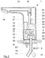
- the mixing fitting 1 chosen as an exemplary embodiment has a mixing device in the form of a mixing valve 3, which is adjustable via an adjusting device 7. It is provided with a controller 20 and a solenoid valve 23.
- the mixing fitting 1 is arranged on a washstand 9.
- the valve 1 has a threaded pin 16 which projects through a tap hole 90 in the wash basin 9.
- a clamping disk 91 is positioned on the washstand 9, which is penetrated by the threaded pin 16 and which is braced with a nut 92 on the wash basin 9.
- a seal 93 is provided between the mixing valve 1 and the washstand 9, a seal 93 is provided.
- the fitting 1 is connected to a cold water connection pipe 17 and a hot water connection pipe 18, with which the mixing fitting 1 is connected to the pipe system of the respective building.
- the mixing valve 1 consists of a fitting housing 10, in which an interior space 11 is formed. In the interior 11, the mixing valve 3, the adjusting device 7, the controller 20 and the solenoid valve 23 are arranged. On the side facing away from the wash basin 9, a connection bore 12 is formed in the mixing fitting 1, which communicates with a discharge channel 13, which terminates in the outlet of the mixing fitting 1 provided with a jet regulator 14. At the end facing the wash basin 9, a base 15 is installed in the fitting housing 10, via which the mixing fitting 1 is in contact with the wash basin 9. On the side into which the spout extends, an infrared window 19 is arranged in the fitting housing 10, behind which the controller 20 is positioned.
- the solenoid valve 23 is in communication with a valve spool 24 which serves to actuate the solenoid valve 23.
- a drive 25 for actuating the mixing valve 3 in the housing 10 is provided.
- the drive 25 is preferably a motor, which may be a servomotor or a stepper motor. In the de-energized state, ie the idle state, the actuating movement of the drive 25 is freely movable.
- the entire components provided in the housing 10 are fastened to a holder 26.
- spacer sleeves 27 are provided for the construction of the mixing valve 3 which correspond with screws 28.
- the connection of the cold water connection pipe 17 and the hot water connection pipe 18 with the connection bore 12 takes place with the interposition of the mixing device via a connection pipe 21, which is sealed with a seal 22 against the connection bore 12.
- the manual temperature setting of the mixing fitting 1 via a handle 29, which is arranged on the outside of the fitting housing 10.
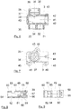
- the mixing device in the form of the mixing valve 3 is formed by a housing, as exemplified in FIG. 6 is shown.
- a mixer shaft 49 is inserted in the assembled state.
- the housing of the mixing valve 3 has an inlet connection 30, which is provided with a connection bore 31 for cold water and a connection bore 33 for hot water.
- the connection bore 31 opens into an inlet 32; the connection bore 33 opens into an inlet 34.
- the inlets 32 and 34 connect the connection bores 31 and 33 with a receiving bore 40 for the mixer shaft 49.
- an outlet nozzle 35 is formed on the housing of the mixing valve 3, which is provided with a connection bore 36 for the exiting mixed water.
- the bottom of the connection bore 36 is formed by a through-passage 37, which opens into connection with an outlet 38 for the mixed water, which in turn communicates with the receiving bore 40 for the mixer shaft 49.
- the outlet nozzle 35 is also provided with holes 39 for - not shown - locking pins.
- the receiving bore 40 for the mixer shaft 49 is provided at its one end with an inlet bore 41 for the mixer shaft 49, which has holes 42 for locking pins 48.
- a threaded bore 43 for receiving a stop screw 62 is introduced into the wall of the inlet bore 41. Outside, the threaded bore 43 is surrounded by a shoulder 44.
- three fastening tabs 45 are formed, which are each provided with a bore 46 and with which the mixing valve 3 in the fitting housing 10 can be fastened.
- the mixer shaft 49 has at its one end a base 50, in which a groove 56 for receiving the mixer shaft lever 70 is formed. In the bottom of the groove 56, a threaded bore 57 is introduced. Externally, a groove 58 is introduced into the base 50, which extends in regions over the circumference of the base 50 and which serves to limit the stop for the mixer shaft 49. Adjacent to the groove 58 is located in the mixer shaft 49, an annular groove 59, which forms an axial securing for the mixer shaft. Adjacent to this annular groove 59, a further annular groove 60 is formed which serves to receive a seal 47. In addition, in the exemplary embodiment, two further annular grooves 60 are also provided for receiving seals 47, with which the mixer shaft 49 is sealed against the receiving bore 40 of the mixing valve 3.
- the mixer shaft 49 is provided with a mixing chamber 54 which is offset on its circumference to each other with an inlet bore 51 for cold water, an inlet bore 52 for hot water and a mixed water outlet channel 53 is provided.
- the mixing chamber 54 ends in a blind hole 55.
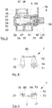
- the adjusting device 7 consists essentially of the mixer shaft lever 70 and a drive shaft lever 77, which are connected to each other via a bracket 82.
- the mixer shaft lever 70 includes a base 71 having a connection bore 74 that merges into a smaller diameter through bore 75.
- On its in the assembled state of the mixer shaft 49 side facing the mixer shaft lever 70 is provided with a shoulder 72 which corresponds to the groove 56 of the mixer shaft 49.
- the paragraph 72 is provided with a flattening 73.
- a screw 61 which is screwed into the threaded bore 57 of the mixer shaft 49.
- At its end facing away from the base 71 of the mixer shaft lever 70 is provided with a bore 76 for fixing the bracket 82.
- the drive shaft lever 77 has a base 78 which is penetrated by a through hole 79. Radially into the through hole 79 projects a threaded hole 80, which serves to receive a locking screw. At the end facing away from the base 78, a bore 81 for fixing the bracket 82 is provided in the drive shaft lever 77.
- the bracket 82 has a U-shaped configuration. As a result, two parallel aligned pins 83 are caused, which are each provided with an annular groove 84.
- the annular grooves 84 take in the assembled state lock washers 85 for reliable attachment of the bracket 82.
- the mixing valve according to the invention in contrast to the known from the prior art mixing valves with manual adjustment of the temperature mixing device, the possibility to make an automatic hygiene flush. This is ensured by the fact that at the beginning of an automatic hygiene flush when opening the solenoid valve 23, the mixing valve 3 can be moved by means of the drive 25 in an open position, which may differ from the random setting of the temperature by the last user. This is ensured by the fact that the drive 25 is in communication with the adjusting device 7, which adjusts the mixer shaft in the predetermined position for a hygiene flush. Depending on the programming, this may be a mix of cold and hot water to ensure that both the cold water line and the hot water level are flushed out with a single flush.
- the solenoid valve 23 is opened to allow the entry of water into the mixing valve according to the invention. After expiration of the preset purge time, the solenoid valve 23 is closed. It can be provided that the mixing valve moves after the predetermined flushing time in a preprogrammed position. Alternatively, it can also be provided that the mixing valve remains in the last rinsing position. Of course, there is the Possibility to specify different flushing times depending on the respective opening positions during programming.
- a bracket by front or bevel gears.
- the use of a belt drive is basically possible here.
- a thermostat can also be used.
- the invention opens up the possibility of providing an automatic hygiene flush also on fittings which are provided with a manual mixing device.
- the mixing fitting according to the invention offers the possibility of arranging the components used also in an electronic washstand fitting of conventional size. Consequently, the mixing fitting according to the invention can be combined with conventional assemblies known from the sanitary sector, without having to make a change to other assemblies here.
- the mixing fitting according to the invention is capable of independently carrying out so-called hygienic rinsing.
- the controller 20 has a time measuring device, in which a time interval is adjustable, after which a forced flushing of the mixing valve according to the invention is to take place. If the mixing valve is not used within the pre-set period of time, an automated hygiene rinse takes place. This is done by a signal emitted by the controller 20, which is directed to the drive 25. The drive 25 comes into operation as a result of this signal, which leads to a movement of the drive shaft lever 77, which in turn via the bracket 82 has a movement of the mixer shaft lever 70 result.
- the drive 25 is in operation until the mixer shaft 49 has reached an open position in which 17 enters the mixing valve 1 from both the hot water connection pipe 18 and from the cold water connection pipe 17.
- this is the middle position, ie the position in which equal amounts of cold and warm water flow through the valve.
- the opening position initially provides a cold water flushing and then provides a hot water flushing, or vice versa.
- the mixer shaft 49 is moved to a mixed water position.
- the solenoid valve 23 is controlled and released the inlet of the mixing valve 1, so that water can enter the valve.
- both the cold water line and the hot water line are flushed by the design according to the invention, whereby a contamination of the upcoming in the lines of water is avoided.
- the controller 20 Upon expiration of a pre-programmed purge time in the controller 20, in which the water flows through the mixing valve, the controller 20 again sends out a signal that causes the solenoid valve 23 to close. There is then no more water in the valve on and off.
- the programming of the controller 20 may provide that the mixing valve 3 or the thermostat is brought by closing the solenoid valve 23 by means of the drive 25 in a predetermined opening position of the cold and / or hot water supply. Regardless of this, the next flushing operation will either occur when a user activates the mixing fixture or once again oversteps the preset period of non-use, again performing a forced sanitary flush as described above.
- a mixing valve is provided which allows a forced flushing of the mixing valve to avoid stagnant water despite manual temperature setting and this simultaneously realized in a housing having the dimensions of conventional mixing valves.
- Such a solution is not known from the prior art.
Landscapes
- Health & Medical Sciences (AREA)
- Life Sciences & Earth Sciences (AREA)
- Engineering & Computer Science (AREA)
- Hydrology & Water Resources (AREA)
- Public Health (AREA)
- Water Supply & Treatment (AREA)
- Domestic Plumbing Installations (AREA)
- Multiple-Way Valves (AREA)
Abstract
Description
- Die Erfindung betrifft eine Mischarmatur mit elektronischer Steuerung und Sensorik zur Benutzererkennung, mit Anschlüssen für Kalt- und Warmwasser und einem elektrisch betätigten Magnetventil sowie einer manuell verstellbaren Mischeinrichtung als Mischventil mit einer Mischerwelle oder als Thermostat. Die Erfindung betrifft außerdem ein Verfahren zur Spülung der Warm- und/oder Kaltwasserleitung mittels einer Mischarmatur.
- Bekanntermaßen kann es bei sanitären Installationen und Armaturen zu gesundheitsschädlichen Verkeimungen des Wassers kommen, insbesondere, wenn über einen längeren Zeitpunkt kein Wasser dem Leitungssystem entnommen wird, sog. Stagnationswasser. Neben der Möglichkeit, eine Verkeimung des Wassers mittels chemischer oder thermischer Verfahren zu bekämpfen, besteht auch die Möglichkeit, eine Verkeimung durch regelmäßiges Spülen des Leitungssystems zu vermeiden.
- Bei elektronischen Armaturen kann eine automatisierte regelmäßige Spülung automatisch durch Ansteuerung der in den Armaturen vorgesehenen Ventile ausgelöst werden. Von großer Bedeutung ist dabei, dass bei dem Spülvorgang sowohl die Kalt- als auch die Warmwasserleitung durchgespült werden.
- Aus der
DE 35 18 644 C2 und derDE 37 18 039 C2 sind Armaturen bekannt, bei denen im Kalt- und Warmwasser-Zulauf je ein motorisch angetriebenes Absperrventil vorgesehen ist. Die gewünschte Mischwassertemperatur wird dabei mittels elektronischer Steuerung durch anteilige Öffnung der beiden Ventile erreicht. Bei diesen elektronischen Armaturen kann eine automatisierte Spülung durch getrennte Öffnung des Kalt- und Warmventils erfolgen. Nachteilig bei diesen Armaturen ist es, dass die Anordnung der motorisch betätigten Ventile in der üblichen Baugröße einer Waschtischarmatur nicht möglich ist. - Aus der
DE 2 821 692 A1 und derDE 10 2011 008 804 B4 sind Armaturen bekannt bei denen im Kalt- und Warmwasser-Zulauf ein manuell betätigtes Thermostatventil vorgesehen ist. In Durchflussrichtung hinter dem Thermostatventil ist ein elektrisch betätigtes Absperrventil, z.B. ein Magnetventil, angeordnet. Bei der aus derDE 101 48 675 C1 bekannten Armatur, bei der im Kalt- und Warmwasser-Zulauf eine manuelle Mischeinrichtung, z.B. eine Mischerwelle, vorgesehen ist, ist in Durchflussrichtung hinter der Mischeinrichtung ein elektrisch betätigtes Absperrventil, z.B. ein Magnetventil, angeordnet. Bei den genannten elektronischen Armaturen kann eine zuverlässige und insbesondere ausreichende automatische Spülung der Kalt- und Warmwasserleitung wegen der Zufallsstellung der Mischeinrichtung nicht sichergestellt werden. - Vor diesem Hintergrund liegt der Erfindung die Aufgabe zugrunde, eine Mischarmatur mit elektronischer Steuerung und manueller Mischeinrichtung zu schaffen, die eine zuverlässige Spülung der Kalt- und Warmwasserleitung sicherstellt und deren Komponenten auch in einer elektronischen Waschtischarmatur üblicher Baugröße angeordnet werden können. Gemäß der Erfindung wird diese Aufgabe dadurch gelöst, dass ein Antrieb vorgesehen ist, der mit einer Verstellvorrichtung verbunden ist, welche mit dem Mischventil oder dem Thermostaten verbunden ist.
- Mit der Erfindung ist eine Mischarmatur mit elektronischer Steuerung und manueller Mischeinrichtung geschaffen, die eine zuverlässige Spülung der Kalt- und Warmwasserleitung sicherstellt und deren Komponenten auch in einer elektronischen Waschtischarmatur üblicher Baugröße angeordnet werden können. Dies ist durch den Antrieb gewährleistet, der über die Verstellvorrichtung eine Bewegung auf das Mischventil oder den Thermostaten überträgt. Somit ist die Möglichkeit geschaffen, im Falle einer Hygienespülung das Mischventil oder den Thermostaten von einer Zufallsstellung, die vom letzten Benutzer gewählt wurde, in eine vorprogrammierte Stellung zu bewegen, um eine zuverlässige Spülung der Kalt- und Warmwasserleitung zu gewährleisten.
- In Weiterbildung der Erfindung ist die Stellbewegung des Antriebs im stromlosen Zustand frei beweglich. Durch diese Ausbildung ist gewährleistet, dass die Mischeinrichtung der Mischarmatur bei normalem Betrieb vom jeweiligen Benutzer manuell uneingeschränkt bedienbar ist. Lediglich im Falle einer Hygienespülung unterliegt die Mischeinrichtung der zwangsweisen Bewegung unter dem Einfluss des Antriebs und der Verstellvorrichtung.
- Die Aufgabe wird darüber hinaus durch ein Verfahren zur Spülung der Warm- und/oder Kaltwasserleitung mittels einer Mischarmatur mit Anschlüssen für Kalt- und Warmwasser und einem elektrisch betätigten Magnetventil sowie einer elektronischer Steuerung und Sensorik zur Benutzererkennung und einer manuell verstellbaren Mischeinrichtung als Mischventil oder als Thermostat, die bei Beginn einer automatischen Hygienespülung mit Öffnen des Magnetventils das Mischventil oder das Thermostat mittels des Antriebs in eine vorgegebene Öffnungsstellung des Kalt- und/oder Warmwasserzulaufs gebracht wird.
- Andere Weiterbildungen und Ausgestaltungen der Erfindung sind in den übrigen Unteransprüchen angegeben. Ausführungsbeispiele der Erfindung sind in den Zeichnungen dargestellt und werden nachfolgend im Einzelnen beschrieben. Es zeigen:
- Figur 1
- die Seitenansicht einer Mischarmatur;
- Figur 2
- den Längsschnitt durch die in
Figur 1 dargestellte Mischarmatur; - Figur 3
- den Schnitt durch eine Mischeinrichtung;
- Figur 4
- die Ansicht einer Verstellvorrichtung;
- Figur 5
- die Draufsicht auf die in
Figur 4 dargestellte Verstellvorrichtung; - Figur 6
- den Schnitt durch die Mischeinrichtung ohne Mischerwelle und Mischwellenhebel;
- Figur 7
- die Draufsicht auf die in
Figur 6 dargestellte Mischeinrichtung; - Figur 8
- den Längsschnitt durch eine Mischerwelle;
- Figur 9
- die Draufsicht auf die in
Figur 8 dargestellte Mischerwelle; - Figur 10
- den Schnitt durch den Mischwellenhebel;
- Figur 11
- die Ansicht auf den in
Figur 10 dargestellten Mischwellenhebel; - Figur 12
- die Ansicht eines Antriebswellenhebels;
- Figur 13
- den Schnitt durch den in
Figur 12 dargestellten Antriebswellenhebel; - Figur 14
- die Ansicht eine Bügels.
- Die als Ausführungsbeispiel gewählte Mischarmatur 1 weist eine Mischeinrichtung in Form eines Mischventils 3 auf, die über eine Verstellvorrichtung 7 einstellbar ist. Sie ist mit einer Steuerung 20 und einem Magnetventil 23 versehen.
- Im Ausführungsbeispiel ist die Mischarmatur 1 auf einem Waschtisch 9 angeordnet. Hierzu weist die Armatur 1 einen Gewindestift 16 auf, der durch ein Hahnloch 90 im Waschtisch 9 ragt. Auf der der Mischarmatur 1 abgewandten Seite ist an dem Waschtisch 9 eine Spannscheibe 91 positioniert, die von dem Gewindestift 16 durchsetzt ist und die mit einer Mutter 92 an dem Waschtisch 9 verspannt ist. Zwischen der Mischarmatur 1 und dem Waschtisch 9 ist eine Dichtung 93 vorgesehen. Die Armatur 1 ist an ein Kaltwasseranschlussrohr 17 und ein Warmwasseranschlussrohr 18 angeschlossen, mit denen die Mischarmatur 1 mit dem Leitungssystem des jeweiligen Gebäudes verbunden ist.
- Die Mischarmatur 1 besteht aus einem Armaturengehäuse 10, in dem ein Innenraum 11 ausgebildet ist. In dem Innenraum 11 sind das Mischventil 3, die Verstellvorrichtung 7, die Steuerung 20 und das Magnetventil 23 angeordnet. Auf der dem Waschtisch 9 abgewandten Seite ist in der Mischarmatur 1 eine Anschlussbohrung 12 ausgebildet, die mit einem Ablaufkanal 13 in Verbindung steht, welcher in dem mit einem Strahlregler 14 versehenen Auslauf der Mischarmatur 1 endet. An dem dem Waschtisch 9 zugewandten Ende ist in dem Armaturengehäuse 10 ein Sockel 15 verbaut, über den die Mischarmatur 1 mit dem Waschtisch 9 in Kontakt steht. Auf der Seite, in die sich der Auslauf erstreckt, ist in dem Armaturengehäuse 10 ein Infrarotfenster 19 angeordnet, hinter dem die Steuerung 20 positioniert ist.
- Das Magnetventil 23 steht mit einer Ventilspule 24 in Verbindung, die zur Betätigung des Magnetventils 23 dient. Darüber hinaus ist ein Antrieb 25 zur Betätigung des Mischventils 3 in dem Gehäuse 10 vorgesehen. Der Antrieb 25 ist vorzugsweise ein Motor, welcher ein Servomotor oder auch ein Schrittmotor sein kann. Im stromlosen Zustand, also dem Ruhezustand, ist die Stellbewegung des Antriebs 25 frei beweglich.
- Die gesamten im Gehäuse 10 vorgesehenen Bauteile sind an einem Halter 26 befestigt. Zudem sind Distanzhülsen 27 zum Aufbau des Mischventils 3 vorgesehen welche mit Schrauben 28 korrespondieren. Die Verbindung des Kaltwasseranschlussrohrs 17 und des Warmwasseranschlussrohrs 18 mit der Anschlussbohrung 12 erfolgt unter Zwischenschaltung der Mischvorrichtung über ein Anschlussrohr 21, welches mit einer Dichtung 22 gegen die Anschlussbohrung 12 abgedichtet ist. Die manuelle Temperatureinstellung der Mischarmatur 1 erfolgt über eine Handhabe 29, die außen an dem Armaturengehäuse 10 angeordnet ist.
- Die Mischeinrichtung in Form des Mischventils 3 ist von einem Gehäuse gebildet, wie es beispielhaft in
Figur 6 dargestellt ist. In das Gehäuse ist in montiertem Zustand eine Mischerwelle 49 eingesetzt. Das Gehäuse des Mischventils 3 weist einen Eintrittsstutzen 30 auf, der mit einer Anschlussbohrung 31 für Kaltwasser und einer Anschlussbohrung 33 für Warmwasser versehen ist. Die Anschlussbohrung 31 mündet in einem Zulauf 32; die Anschlussbohrung 33 mündet in einem Zulauf 34. Die Zuläufe 32 und 34 verbinden die Anschlussbohrungen 31 und 33 mit einer Aufnahmebohrung 40 für die Mischerwelle 49. - Auf der dem Eintrittsstutzen 30 abgewandten Seite ist an dem Gehäuse des Mischventils 3 ein Austrittsstutzen 35 ausgebildet, welcher mit einer Anschlussbohrung 36 für das austretende Mischwasser versehen ist. Der Boden der Anschlussbohrung 36 ist gebildet von einem Durchgangskanal 37, welche in Verbindung mit einem Auslauf 38 für das Mischwasser mündet, welcher wiederum mit der Aufnahmebohrung 40 für die Mischerwelle 49 in Verbindung steht. Der Austrittsstutzen 35 ist zudem mit Bohrungen 39 für - nicht dargestellte - Sicherungsstifte versehen.
- Die Aufnahmebohrung 40 für die Mischerwelle 49 ist an ihrem einen Ende mit einer Eintrittsbohrung 41 für die Mischerwelle 49 versehen, welche Bohrungen 42 für Sicherungsstifte 48 aufweist. Radial zur Aufnahmebohrung 40 ist in die Wandung der Eintrittsbohrung 41 eine Gewindebohrung 43 zur Aufnahme einer Anschlagschraube 62 eingebracht. Außen ist die Gewindebohrung 43 von einem Absatz 44 umgeben. An dem Umfang des Gehäuses des Michventils 3 sind im Ausführungsbeispiel drei Befestigungslaschen 45 ausgebildet, die jeweils mit einer Bohrung 46 versehen sind und mit denen das Mischventil 3 in dem Armaturengehäuse 10 befestigbar ist.
- Die Mischerwelle 49 weist an ihrem einen Ende einen Sockel 50 auf, in dem eine Nut 56 zur Aufnahme des Mischerwellenhebels 70 ausgebildet ist. In den Boden der Nut 56 ist eine Gewindebohrung 57 eingebracht. Außen ist in den Sockel 50 eine Nut 58 eingebracht, die sich bereichsweise über den Umfang des Sockels 50 erstreckt und die zur Anschlagbegrenzung für die Mischerwelle 49 dient. Benachbart zu der Nut 58 befindet sich in der Mischerwelle 49 eine Ringnut 59, die eine axiale Sicherung für die Mischerwelle bildet. Zu dieser Ringnut 59 benachbart ist eine weitere Ringnut 60 ausgebildet, die zur Aufnahme einer Dichtung 47 dient. Darüber hinaus sind im Ausführungsbeispiel zwei weitere Ringnuten 60 ebenfalls zur Aufnahme von Dichtungen 47 vorgesehen, mit denen die Mischerwelle 49 gegen die Aufnahmebohrung 40 des Mischventils 3 abgedichtet ist.
- Die Mischerwelle 49 ist mit einer Mischkammer 54 versehen, die auf ihrem Umfang versetzt zueinander mit einer Eintrittsbohrung 51 für Kaltwasser, einer Eintrittsbohrung 52 für Warmwasser sowie einem Mischwasseraustrittskanal 53 versehen ist. Die Mischkammer 54 endet in einer Sacklochbohrung 55.
- Die Verstellvorrichtung 7 besteht im Wesentlichen aus dem Mischerwellenhebel 70 und einem Antriebswellenhebel 77, welche über einen Bügel 82 miteinander verbunden sind. Der Mischerwellenhebel 70 umfasst einen Sockel 71, der eine Anschlussbohrung 74 hat, die in eine im Durchmesser kleinere Durchgangsbohrung 75 übergeht. Auf seiner in montiertem Zustand der Mischerwelle 49 zugewandten Seite ist der Mischerwellenhebel 70 mit einem Absatz 72 versehen, der mit der Nut 56 der Mischerwelle 49 korrespondiert. Hierzu ist der Absatz 72 mit einer Abflachung 73 versehen. Zur Montage des Mischerwellenhebels 70 an der Mischerwelle 49 dient eine Schraube 61, die in die Gewindebohrung 57 der Mischerwelle 49 einschraubbar ist. An seinem dem Sockel 71 abgewandten Ende ist der Mischerwellenhebel 70 mit einer Bohrung 76 zur Befestigung des Bügels 82 versehen.
- Der Antriebswellen Hebel 77 weist einen Sockel 78 auf, der von einer Durchgangsbohrung 79 durchsetzt ist. Radial in die Durchgangsbohrung 79 ragt eine Gewindebohrung 80, die zur Aufnahme einer Sicherungsschraube dient. An dem dem Sockel 78 abgewandten Ende ist in dem Antriebswellenhebel 77 eine Bohrung 81 zur Befestigung des Bügels 82 vorgesehen.
- Der Bügel 82 hat eine U-förmige Ausbildung. Hierdurch sind zwei parallel zueinander ausgerichtete Stifte 83 hervorgerufen, welche jeweils mit einer Ringnut 84 versehen sind. Die Ringnuten 84 nehmen in montiertem Zustand Sicherungsscheiben 85 zur zuverlässigen Befestigung des Bügels 82 auf.
- Mit der erfindungsgemäßen Mischarmatur besteht im Gegensatz zu den aus dem Stand der Technik bekannten Mischarmaturen mit manueller Verstellung der Temperaturmischeinrichtung die Möglichkeit, eine automatische Hygienespülung vorzunehmen. Dies ist dadurch gewährleistet, dass bei Beginn einer automatischen Hygienespülung beim Öffnen des Magnetventils 23 das Mischventil 3 mit Hilfe des Antriebs 25 in eine Öffnungsstellung bewegt werden kann, die von der zufälligen Einstellung der Temperatur durch den letzten Benutzer abweichen kann. Dies ist dadurch gewährleistet, dass der Antrieb 25 mit der Verstellvorrichtung 7 in Verbindung steht, welche die Mischerwelle in die vorgegebene Stellung für eine Hygienespülung verstellt. Je nach Programmierung kann dies eine Mischstellung aus kaltem und warmem Wasser sein, um mit nur einer Spülung zu gewährleisten, dass sowohl der Kaltwasserstrang als auch der Warmwasserstand durchspült wird. Alternativ kann auch vorgesehen sein, dass zunächst eine Kaltwassereinstellung gewählt wird und nach einer ausreichenden Zeit die Warmwasserstellung eingenommen wird oder umgekehrt. Wichtig ist bekanntermaßen, dass beide Stränge gespült werden. Zur Durchführung der Spülung wird das Magnetventil 23 geöffnet, um den Eintritt von Wasser in die erfindungsgemäße Mischarmatur zu ermöglichen. Nach Ablauf der voreingestellten Spülzeit wird das Magnetventil 23 geschlossen. Es kann vorgesehen sein, dass das Mischventil nach der vorgegebenen Spülzeit in eine vorprogrammierte Stellung fährt. Alternativ kann auch vorgesehen sein, dass das Mischventil in der letzten Spülposition verbleibt. Selbstverständlich besteht die Möglichkeit, im Rahmen der Programmierung unterschiedliche Spülzeiten in Abhängigkeit von den jeweiligen Öffnungsstellungen vorzugeben.
- In Abwandlung des Ausführungsbeispiels besteht auch die Möglichkeit, die Verstellvorrichtung 7 anstelle eines Bügels durch Stirn- oder Kegelzahnräder zu realisieren. Auch die Verwendung eines Riemenantriebs ist hier grundsätzlich möglich. Anstelle des im Ausführungsbeispiel gewählten Mischventils 3 mit einer Mischerwelle 49 kann auch ein Thermostat Anwendung finden.
- Die Erfindung eröffnet die Möglichkeit, eine automatische Hygienespülung auch an Armaturen vorzusehen, die mit einer manuellen Mischeinrichtung versehen sind. Gleichzeitig bietet die erfindungsgemäße Mischarmatur die Möglichkeit, die verwendeten Komponenten auch in einer elektronischen Waschtischarmatur üblicher Baugröße anzuordnen. Folglich lässt sich die erfindungsgemäße Mischarmatur mit üblichen aus dem Sanitärbereich bekannten Baugruppen kombinieren, ohne hier eine Veränderung an anderen Baugruppen vornehmen zu müssen.
- Zur Vermeidung von Verkeimung des in den Kalt- und Warmwasserleitungen anstehenden Wassers ist die erfindungsgemäße Mischarmatur zur selbständigen Durchführung so genannter Hygienespülungen in der Lage. Hierzu verfügt die Steuerung 20 über eine Zeitmesseinrichtung, in der ein Zeitintervall einstellbar ist, nach welchen eine Zwangsspülung der erfindungsgemäßen Mischarmatur erfolgen soll. Wird innerhalb des voreingestellten Zeitraums die Mischarmatur nicht benutzt, erfolgt eine automatisierte Hygienespülung. Dies erfolgt durch ein von der Steuerung 20 ausgesandtes Signal, welches an den Antrieb 25 gerichtet wird. Der Antrieb 25 tritt infolge dieses Signals in Funktion, was zu einer Bewegung des Antriebswellenhebels 77 führt, was über den Bügel 82 wiederum eine Bewegung des Mischerwellenhebels 70 zur Folge hat. Der Antrieb 25 ist so lange in Betrieb, bis die Mischerwelle 49 eine Öffnungsstellung erreicht hat, in der sowohl aus dem Heißwasser-Anschlussrohr 18 als auch aus dem Kaltwasser-Anschlussrohr 17 Wasser in die Mischarmatur 1 eintritt. Vorzugsweise ist dies die Mittelstellung, also die Stellung, in der gleiche Mengen kaltes und warmes Wasser durch die Armatur strömen. Alternativ kann auch vorgesehen sein, dass die Öffnungsstellung zunächst eine Kaltwasserspülung vorsieht und danach eine Warmwasserspülung vorsieht, oder umgekehrt. Dadurch wird die Mischerwelle 49 in eine Mischwasserposition bewegt. Sodann wird das Magnetventil 23 angesteuert und der Zulauf der Mischarmatur 1 freigegeben, so dass Wasser in die Armatur eintreten kann.
- In jedem Fall werden durch die erfindungsgemäße Gestaltung sowohl die Kaltwasserleitung als auch die Heißwasserleitung gespült, wodurch eine Verkeimung des in den Leitungen anstehenden Wassers vermieden ist. Nach Ablauf einer in der Steuerung 20 vorprogrammierten Spülzeit, in der das Wasser durch die Mischarmatur fließt, sendet die Steuerung 20 erneut ein Signal aus, die das Magnetventil 23 dazu veranlasst, zu schließen. Es tritt dann kein Wasser mehr in die Armatur ein und aus. Die Programmierung der Steuerung 20 kann vorsehen, dass das Mischventil 3 oder das Thermostat nach Schließen des Magnetventils 23 mittels des Antriebs 25 in eine vorgegebene Öffnungsstellung des Kalt- und/oder Warmwasserzulaufs gebracht wird. Unabhängig davon erfolgt der nächste Spülvorgang entweder, wenn ein Benutzer die Mischarmatur in Funktion setzt oder der voreingestellte Zeitraum der Nichtbenutzung erneut überschritten wird und somit erneut eine zwangsweise Hygienespülung, wie sie vorstehend beschrieben ist, durchgeführt wird.
- Mit der Erfindung ist eine Mischarmatur geschaffen, die eine zwangsweise Spülung der Mischarmatur zur Vermeidung von Stagnationswasser trotz manueller Temperatureinstellung ermöglicht und dies gleichzeitig in einem Gehäuse, welches die Abmessungen üblicher Mischarmaturen hat, realisiert. Eine solche Lösung ist aus dem Stand der Technik nicht bekannt.
Claims (16)
- Mischarmatur mit elektronischer Steuerung (20) und Sensorik zur Benutzererkennung, mit Anschlüssen für Kalt- und Warmwasser und einem elektrisch betätigten Magnetventil (23) sowie einer manuell verstellbaren Mischeinrichtung als Mischventil (3) mit einer Mischerwelle (49) oder als Thermostat, dadurch gekennzeichnet, dass ein Antrieb (25) vorgesehen ist, der mit einer Verstellvorrichtung (7) verbunden ist, welche mit dem Mischventil (3) oder dem Thermostaten verbunden ist.
- Mischarmatur nach Anspruch 1, dadurch gekennzeichnet, dass der Antrieb (25) elektrisch betrieben ist.
- Mischarmatur nach Anspruch 1 oder 2, dadurch gekennzeichnet, dass der Antrieb (25) ein Motor ist.
- Mischarmatur nach einem der Ansprüche 1 bis 3, dadurch gekennzeichnet, dass der Antrieb (25) ein Servomotor ist.
- Mischarmatur nach einem der Ansprüche 1 bis 3, dadurch gekennzeichnet, dass der Antrieb (25) ein Schrittmotor ist.
- Mischarmatur nach einem der vorgenannten Ansprüche, dadurch gekennzeichnet, dass der Antrieb (25) in einem Innenraum (11) des Armaturengehäuses (10) angeordnet ist.
- Mischarmatur nach einem der vorgenannten Ansprüche, dadurch gekennzeichnet, dass die Stellbewegung des Antriebs (25) im stromlosen Zustand frei beweglich ist.
- Mischarmatur nach einem der vorgenannten Ansprüche, dadurch gekennzeichnet, dass das Mischventil (3) oder das Thermostat über einen Bügel (83) miteinander verbunden sind.
- Mischarmatur nach einem der vorgenannten Ansprüche, dadurch gekennzeichnet, dass das Mischventil (3) oder das Thermostat mittels Stirn- oder Kegelzahnrädern miteinander verbunden sind.
- Mischarmatur nach einem der vorgenannten Ansprüche, dadurch gekennzeichnet, dass das Mischventil (3) oder das Thermostat mittels Riemenantrieb miteinander verbunden sind.
- Verfahren zur Spülung der Warm- und/oder Kaltwasserleitung mittels einer Mischarmatur mit Anschlüssen für Kalt- und Warmwasser und einem elektrisch betätigten Magnetventil (23) sowie einer elektronischer Steuerung (20) und Sensorik zur Benutzererkennung und einer manuell verstellbaren Mischeinrichtung als Mischventil (3) oder als Thermostat, dadurch gekennzeichnet, dass bei Beginn einer automatischen Hygienespülung mit Öffnen des Magnetventils (23) das Mischventil (3) oder das Thermostat mittels des Antriebs (25) in eine vorgegebene Öffnungsstellung des Kalt- und/oder Warmwasserzulaufs gebracht wird.
- Verfahren nach Anspruch 11, dadurch gekennzeichnet, dass die Öffnungsstellung eine Mittelstellung ist, bei der gleichzeitig die Warm- und Kaltwasserleitung gespült wird.
- Verfahren nach Anspruch 11, dadurch gekennzeichnet, dass die Öffnungsstellung eine Stellung ist, in der die Warm- und Kaltwasserleitung. nacheinander gespült wird.
- Verfahren nach einem der Ansprüche 11 bis 13, dadurch gekennzeichnet, dass nach Ablauf der vorprogrammierten Spülzeit das Magnetventil (23) geschlossen wird.
- Verfahren nach einem der Ansprüche Anspruch 11 bis 14, dadurch gekennzeichnet, dass die Spülzeiten in Abhängigkeit der jeweiligen Öffnungsstellung vorprogrammiert werden.
- Verfahren nach einem der Ansprüche Anspruch 11 bis 15, dadurch gekennzeichnet, dass das Mischventil (3) oder das Thermostat nach Schließen des Magnetventils (23) mittels des Antriebs (25) in eine vorgegebene Öffnungsstellung des Kalt- und/oder Warmwasserzulaufs gebracht wird.
Applications Claiming Priority (1)
| Application Number | Priority Date | Filing Date | Title |
|---|---|---|---|
| DE102018104571.9A DE102018104571A1 (de) | 2018-02-28 | 2018-02-28 | Mischarmatur |
Publications (2)
| Publication Number | Publication Date |
|---|---|
| EP3533941A1 true EP3533941A1 (de) | 2019-09-04 |
| EP3533941B1 EP3533941B1 (de) | 2025-01-08 |
Family
ID=65628604
Family Applications (1)
| Application Number | Title | Priority Date | Filing Date |
|---|---|---|---|
| EP19159569.3A Active EP3533941B1 (de) | 2018-02-28 | 2019-02-27 | Mischarmatur |
Country Status (2)
| Country | Link |
|---|---|
| EP (1) | EP3533941B1 (de) |
| DE (1) | DE102018104571A1 (de) |
Cited By (1)
| Publication number | Priority date | Publication date | Assignee | Title |
|---|---|---|---|---|
| CN113958747A (zh) * | 2020-07-21 | 2022-01-21 | 路达(厦门)工业有限公司 | 感应出水龙头 |
Families Citing this family (2)
| Publication number | Priority date | Publication date | Assignee | Title |
|---|---|---|---|---|
| DE202021004307U1 (de) | 2021-11-11 | 2023-07-25 | Schell GmbH & Co. KG. | Mischarmatur |
| DE102021129400A1 (de) | 2021-11-11 | 2023-05-11 | Schell Gmbh & Co. Kg | Mischarmatur |
Citations (7)
| Publication number | Priority date | Publication date | Assignee | Title |
|---|---|---|---|---|
| DE2821692A1 (de) | 1978-05-18 | 1979-11-22 | Hansa Metallwerke Ag | Sanitaere mischwasser-armatur |
| DE3518644C2 (de) | 1985-05-23 | 1989-01-26 | Knebel & Roettger Gmbh & Co, 5860 Iserlohn, De | |
| DE3718039C2 (de) | 1987-05-28 | 1994-04-21 | Ideal Standard | Elektronisch temperaturgeregelte Mischarmatur |
| DE10148675C1 (de) | 2001-10-02 | 2003-12-04 | Mepa Pauli Und Menden Gmbh Wie | Wasserarmatur mit Anwesenheitsdetektor |
| DE102011008804B4 (de) | 2011-01-18 | 2012-09-20 | Schell Gmbh & Co. Kg | Sanitärarmatur |
| DE102014104393A1 (de) * | 2013-04-05 | 2014-10-09 | Herbert Wimberger | Sanitärarmatur mit Präventivspülung |
| DE202016004151U1 (de) * | 2016-07-05 | 2017-04-07 | Klaus Michael Held | Elektronische Steuerung für Sanitärarmaturen mit bedarfsangepassten Durchflüssen und Steuerungselektronik über elektronischen Drehschalter oder zeitabhängiger elektronischer Tastersteuerung auch in Verbindung mit berührungsfreier Sensorelektronik |
Family Cites Families (2)
| Publication number | Priority date | Publication date | Assignee | Title |
|---|---|---|---|---|
| GB0500970D0 (en) * | 2005-01-18 | 2005-02-23 | Kohler Mira Ltd | Improvements in or relating to ablutionary Installations |
| AT10563U1 (de) * | 2007-12-20 | 2009-06-15 | Herbert Wimberger | Verfahren zur thermischen desinfektion und armaturen zum durchfuhren dieser verfahren |
-
2018
- 2018-02-28 DE DE102018104571.9A patent/DE102018104571A1/de active Pending
-
2019
- 2019-02-27 EP EP19159569.3A patent/EP3533941B1/de active Active
Patent Citations (7)
| Publication number | Priority date | Publication date | Assignee | Title |
|---|---|---|---|---|
| DE2821692A1 (de) | 1978-05-18 | 1979-11-22 | Hansa Metallwerke Ag | Sanitaere mischwasser-armatur |
| DE3518644C2 (de) | 1985-05-23 | 1989-01-26 | Knebel & Roettger Gmbh & Co, 5860 Iserlohn, De | |
| DE3718039C2 (de) | 1987-05-28 | 1994-04-21 | Ideal Standard | Elektronisch temperaturgeregelte Mischarmatur |
| DE10148675C1 (de) | 2001-10-02 | 2003-12-04 | Mepa Pauli Und Menden Gmbh Wie | Wasserarmatur mit Anwesenheitsdetektor |
| DE102011008804B4 (de) | 2011-01-18 | 2012-09-20 | Schell Gmbh & Co. Kg | Sanitärarmatur |
| DE102014104393A1 (de) * | 2013-04-05 | 2014-10-09 | Herbert Wimberger | Sanitärarmatur mit Präventivspülung |
| DE202016004151U1 (de) * | 2016-07-05 | 2017-04-07 | Klaus Michael Held | Elektronische Steuerung für Sanitärarmaturen mit bedarfsangepassten Durchflüssen und Steuerungselektronik über elektronischen Drehschalter oder zeitabhängiger elektronischer Tastersteuerung auch in Verbindung mit berührungsfreier Sensorelektronik |
Cited By (1)
| Publication number | Priority date | Publication date | Assignee | Title |
|---|---|---|---|---|
| CN113958747A (zh) * | 2020-07-21 | 2022-01-21 | 路达(厦门)工业有限公司 | 感应出水龙头 |
Also Published As
| Publication number | Publication date |
|---|---|
| DE102018104571A1 (de) | 2019-08-29 |
| EP3533941B1 (de) | 2025-01-08 |
Similar Documents
| Publication | Publication Date | Title |
|---|---|---|
| EP3115518B1 (de) | Sanitärarmatur mit zwei ventilen | |
| EP2387740B1 (de) | Elektronisch regelbare mischvorrichtung für leitungswasser | |
| EP3420430B1 (de) | Thermostat-mischventil | |
| EP3533941B1 (de) | Mischarmatur | |
| EP2564283A1 (de) | Sanitäre mischbatterie, insbesondere für eine brausevorrichtung | |
| EP3637216B1 (de) | Anordnung und verfahren zur regelung des ausgangs-fliessdrucks einer wasserarmatur | |
| DE102011008804B4 (de) | Sanitärarmatur | |
| DE102004014126B3 (de) | Sanitär-Armatur zur Unterputz-Montage | |
| DE19525358C2 (de) | Einhebelmischbatterie zur Unterputzmontage | |
| WO1994018509A1 (de) | Adapterarmatur zum wahlweisen anschluss eines heizkörpers | |
| EP2982805B1 (de) | Multifunktionales anschlusszwischenstück und verwendungen des anschlusszwischenstücks | |
| DE102013101591B4 (de) | Eckventil | |
| DE4345197A1 (de) | Vorrichtung, insbesondere Patrone zum Einbau in eine Anschlußgarnitur zum Anschluß eines Heizkörpers | |
| EP3564664B1 (de) | Wasserarmatur mit spülautomatik | |
| EP2169124B1 (de) | Elektronisch steuerbare Armatur zum Mischen von kaltem und warmen Wasser, insbesondere für einen Waschtisch | |
| EP3098356B1 (de) | Sanitärarmatur mit sowohl manueller als auch elektrischer betätigung | |
| DE2007572A1 (de) | Waschtisch mit einem Wasserausfluß | |
| DE102021129400A1 (de) | Mischarmatur | |
| DE202021004307U1 (de) | Mischarmatur | |
| EP2604896B1 (de) | Mischvorrichtung für Leitungswasser | |
| DE2252395C3 (de) | Umschalter für ein System Wanne-Brause | |
| DE102005001310A1 (de) | Sanitärarmatur | |
| EP4286614A1 (de) | Sanitärarmatur mit absperrventilen | |
| EP3330444B1 (de) | Auslaufarmatur mit rückflusssicherung | |
| DE102021127586A1 (de) | Vorrichtung zur Durchführung von Hygienespülungen in Sanitärarmaturen |
Legal Events
| Date | Code | Title | Description |
|---|---|---|---|
| PUAI | Public reference made under article 153(3) epc to a published international application that has entered the european phase |
Free format text: ORIGINAL CODE: 0009012 |
|
| STAA | Information on the status of an ep patent application or granted ep patent |
Free format text: STATUS: THE APPLICATION HAS BEEN PUBLISHED |
|
| AK | Designated contracting states |
Kind code of ref document: A1 Designated state(s): AL AT BE BG CH CY CZ DE DK EE ES FI FR GB GR HR HU IE IS IT LI LT LU LV MC MK MT NL NO PL PT RO RS SE SI SK SM TR |
|
| AX | Request for extension of the european patent |
Extension state: BA ME |
|
| STAA | Information on the status of an ep patent application or granted ep patent |
Free format text: STATUS: REQUEST FOR EXAMINATION WAS MADE |
|
| 17P | Request for examination filed |
Effective date: 20200302 |
|
| RBV | Designated contracting states (corrected) |
Designated state(s): AL AT BE BG CH CY CZ DE DK EE ES FI FR GB GR HR HU IE IS IT LI LT LU LV MC MK MT NL NO PL PT RO RS SE SI SK SM TR |
|
| STAA | Information on the status of an ep patent application or granted ep patent |
Free format text: STATUS: EXAMINATION IS IN PROGRESS |
|
| 17Q | First examination report despatched |
Effective date: 20201201 |
|
| GRAP | Despatch of communication of intention to grant a patent |
Free format text: ORIGINAL CODE: EPIDOSNIGR1 |
|
| STAA | Information on the status of an ep patent application or granted ep patent |
Free format text: STATUS: GRANT OF PATENT IS INTENDED |
|
| INTG | Intention to grant announced |
Effective date: 20240920 |
|
| GRAS | Grant fee paid |
Free format text: ORIGINAL CODE: EPIDOSNIGR3 |
|
| GRAA | (expected) grant |
Free format text: ORIGINAL CODE: 0009210 |
|
| STAA | Information on the status of an ep patent application or granted ep patent |
Free format text: STATUS: THE PATENT HAS BEEN GRANTED |
|
| AK | Designated contracting states |
Kind code of ref document: B1 Designated state(s): AL AT BE BG CH CY CZ DE DK EE ES FI FR GB GR HR HU IE IS IT LI LT LU LV MC MK MT NL NO PL PT RO RS SE SI SK SM TR |
|
| REG | Reference to a national code |
Ref country code: GB Ref legal event code: FG4D Free format text: NOT ENGLISH |
|
| REG | Reference to a national code |
Ref country code: CH Ref legal event code: EP |
|
| REG | Reference to a national code |
Ref country code: DE Ref legal event code: R096 Ref document number: 502019012760 Country of ref document: DE |
|
| REG | Reference to a national code |
Ref country code: IE Ref legal event code: FG4D Free format text: LANGUAGE OF EP DOCUMENT: GERMAN |
|
| P01 | Opt-out of the competence of the unified patent court (upc) registered |
Free format text: CASE NUMBER: APP_4884/2025 Effective date: 20250129 |
|
| REG | Reference to a national code |
Ref country code: NL Ref legal event code: FP |
|
| REG | Reference to a national code |
Ref country code: LT Ref legal event code: MG9D |
|
| PG25 | Lapsed in a contracting state [announced via postgrant information from national office to epo] |
Ref country code: RS Free format text: LAPSE BECAUSE OF FAILURE TO SUBMIT A TRANSLATION OF THE DESCRIPTION OR TO PAY THE FEE WITHIN THE PRESCRIBED TIME-LIMIT Effective date: 20250408 |
|
| PG25 | Lapsed in a contracting state [announced via postgrant information from national office to epo] |
Ref country code: FI Free format text: LAPSE BECAUSE OF FAILURE TO SUBMIT A TRANSLATION OF THE DESCRIPTION OR TO PAY THE FEE WITHIN THE PRESCRIBED TIME-LIMIT Effective date: 20250108 |
|
| PG25 | Lapsed in a contracting state [announced via postgrant information from national office to epo] |
Ref country code: PL Free format text: LAPSE BECAUSE OF FAILURE TO SUBMIT A TRANSLATION OF THE DESCRIPTION OR TO PAY THE FEE WITHIN THE PRESCRIBED TIME-LIMIT Effective date: 20250108 |
|
| PG25 | Lapsed in a contracting state [announced via postgrant information from national office to epo] |
Ref country code: ES Free format text: LAPSE BECAUSE OF FAILURE TO SUBMIT A TRANSLATION OF THE DESCRIPTION OR TO PAY THE FEE WITHIN THE PRESCRIBED TIME-LIMIT Effective date: 20250108 |
|
| PG25 | Lapsed in a contracting state [announced via postgrant information from national office to epo] |
Ref country code: IS Free format text: LAPSE BECAUSE OF FAILURE TO SUBMIT A TRANSLATION OF THE DESCRIPTION OR TO PAY THE FEE WITHIN THE PRESCRIBED TIME-LIMIT Effective date: 20250508 Ref country code: NO Free format text: LAPSE BECAUSE OF FAILURE TO SUBMIT A TRANSLATION OF THE DESCRIPTION OR TO PAY THE FEE WITHIN THE PRESCRIBED TIME-LIMIT Effective date: 20250408 |
|
| PG25 | Lapsed in a contracting state [announced via postgrant information from national office to epo] |
Ref country code: HR Free format text: LAPSE BECAUSE OF FAILURE TO SUBMIT A TRANSLATION OF THE DESCRIPTION OR TO PAY THE FEE WITHIN THE PRESCRIBED TIME-LIMIT Effective date: 20250108 |
|
| PG25 | Lapsed in a contracting state [announced via postgrant information from national office to epo] |
Ref country code: LV Free format text: LAPSE BECAUSE OF FAILURE TO SUBMIT A TRANSLATION OF THE DESCRIPTION OR TO PAY THE FEE WITHIN THE PRESCRIBED TIME-LIMIT Effective date: 20250108 Ref country code: PT Free format text: LAPSE BECAUSE OF FAILURE TO SUBMIT A TRANSLATION OF THE DESCRIPTION OR TO PAY THE FEE WITHIN THE PRESCRIBED TIME-LIMIT Effective date: 20250508 |
|
| PG25 | Lapsed in a contracting state [announced via postgrant information from national office to epo] |
Ref country code: GR Free format text: LAPSE BECAUSE OF FAILURE TO SUBMIT A TRANSLATION OF THE DESCRIPTION OR TO PAY THE FEE WITHIN THE PRESCRIBED TIME-LIMIT Effective date: 20250409 Ref country code: BG Free format text: LAPSE BECAUSE OF FAILURE TO SUBMIT A TRANSLATION OF THE DESCRIPTION OR TO PAY THE FEE WITHIN THE PRESCRIBED TIME-LIMIT Effective date: 20250108 |
|
| PG25 | Lapsed in a contracting state [announced via postgrant information from national office to epo] |
Ref country code: SE Free format text: LAPSE BECAUSE OF FAILURE TO SUBMIT A TRANSLATION OF THE DESCRIPTION OR TO PAY THE FEE WITHIN THE PRESCRIBED TIME-LIMIT Effective date: 20250108 |
|
| REG | Reference to a national code |
Ref country code: CH Ref legal event code: PL |
|
| PG25 | Lapsed in a contracting state [announced via postgrant information from national office to epo] |
Ref country code: SM Free format text: LAPSE BECAUSE OF FAILURE TO SUBMIT A TRANSLATION OF THE DESCRIPTION OR TO PAY THE FEE WITHIN THE PRESCRIBED TIME-LIMIT Effective date: 20250108 |
|
| REG | Reference to a national code |
Ref country code: DE Ref legal event code: R097 Ref document number: 502019012760 Country of ref document: DE |
|
| PG25 | Lapsed in a contracting state [announced via postgrant information from national office to epo] |
Ref country code: DK Free format text: LAPSE BECAUSE OF FAILURE TO SUBMIT A TRANSLATION OF THE DESCRIPTION OR TO PAY THE FEE WITHIN THE PRESCRIBED TIME-LIMIT Effective date: 20250108 |
|
| PG25 | Lapsed in a contracting state [announced via postgrant information from national office to epo] |
Ref country code: MC Free format text: LAPSE BECAUSE OF FAILURE TO SUBMIT A TRANSLATION OF THE DESCRIPTION OR TO PAY THE FEE WITHIN THE PRESCRIBED TIME-LIMIT Effective date: 20250108 |
|
| PG25 | Lapsed in a contracting state [announced via postgrant information from national office to epo] |
Ref country code: LU Free format text: LAPSE BECAUSE OF NON-PAYMENT OF DUE FEES Effective date: 20250227 |
|
| PG25 | Lapsed in a contracting state [announced via postgrant information from national office to epo] |
Ref country code: CH Free format text: LAPSE BECAUSE OF NON-PAYMENT OF DUE FEES Effective date: 20250228 |
|
| PG25 | Lapsed in a contracting state [announced via postgrant information from national office to epo] |
Ref country code: CZ Free format text: LAPSE BECAUSE OF FAILURE TO SUBMIT A TRANSLATION OF THE DESCRIPTION OR TO PAY THE FEE WITHIN THE PRESCRIBED TIME-LIMIT Effective date: 20250108 Ref country code: EE Free format text: LAPSE BECAUSE OF FAILURE TO SUBMIT A TRANSLATION OF THE DESCRIPTION OR TO PAY THE FEE WITHIN THE PRESCRIBED TIME-LIMIT Effective date: 20250108 |
|
| PG25 | Lapsed in a contracting state [announced via postgrant information from national office to epo] |
Ref country code: RO Free format text: LAPSE BECAUSE OF FAILURE TO SUBMIT A TRANSLATION OF THE DESCRIPTION OR TO PAY THE FEE WITHIN THE PRESCRIBED TIME-LIMIT Effective date: 20250108 |
|
| PG25 | Lapsed in a contracting state [announced via postgrant information from national office to epo] |
Ref country code: SK Free format text: LAPSE BECAUSE OF FAILURE TO SUBMIT A TRANSLATION OF THE DESCRIPTION OR TO PAY THE FEE WITHIN THE PRESCRIBED TIME-LIMIT Effective date: 20250108 |
|
| PLBE | No opposition filed within time limit |
Free format text: ORIGINAL CODE: 0009261 |
|
| STAA | Information on the status of an ep patent application or granted ep patent |
Free format text: STATUS: NO OPPOSITION FILED WITHIN TIME LIMIT |
|
| 26N | No opposition filed |
Effective date: 20251009 |
|
| GBPC | Gb: european patent ceased through non-payment of renewal fee |
Effective date: 20250408 |
|
| PG25 | Lapsed in a contracting state [announced via postgrant information from national office to epo] |
Ref country code: GB Free format text: LAPSE BECAUSE OF NON-PAYMENT OF DUE FEES Effective date: 20250408 |
|
| PG25 | Lapsed in a contracting state [announced via postgrant information from national office to epo] |
Ref country code: FR Free format text: LAPSE BECAUSE OF NON-PAYMENT OF DUE FEES Effective date: 20250308 |
|
| PG25 | Lapsed in a contracting state [announced via postgrant information from national office to epo] |
Ref country code: IE Free format text: LAPSE BECAUSE OF NON-PAYMENT OF DUE FEES Effective date: 20250227 |
|
| PG25 | Lapsed in a contracting state [announced via postgrant information from national office to epo] |
Ref country code: IT Free format text: LAPSE BECAUSE OF FAILURE TO SUBMIT A TRANSLATION OF THE DESCRIPTION OR TO PAY THE FEE WITHIN THE PRESCRIBED TIME-LIMIT Effective date: 20250108 |
|
| PGFP | Annual fee paid to national office [announced via postgrant information from national office to epo] |
Ref country code: NL Payment date: 20260218 Year of fee payment: 8 |
|
| PGFP | Annual fee paid to national office [announced via postgrant information from national office to epo] |
Ref country code: DE Payment date: 20260303 Year of fee payment: 8 |
|
| PGFP | Annual fee paid to national office [announced via postgrant information from national office to epo] |
Ref country code: AT Payment date: 20260319 Year of fee payment: 8 |
|
| PGFP | Annual fee paid to national office [announced via postgrant information from national office to epo] |
Ref country code: BE Payment date: 20260226 Year of fee payment: 8 |