EP3534036B1 - Transmission toroïdale à variation continue - Google Patents
Transmission toroïdale à variation continue Download PDFInfo
- Publication number
- EP3534036B1 EP3534036B1 EP17866028.8A EP17866028A EP3534036B1 EP 3534036 B1 EP3534036 B1 EP 3534036B1 EP 17866028 A EP17866028 A EP 17866028A EP 3534036 B1 EP3534036 B1 EP 3534036B1
- Authority
- EP
- European Patent Office
- Prior art keywords
- cam plate
- disc
- cam
- axis line
- rotational axis
- Prior art date
- Legal status (The legal status is an assumption and is not a legal conclusion. Google has not performed a legal analysis and makes no representation as to the accuracy of the status listed.)
- Active
Links
Images



Classifications
-
- F—MECHANICAL ENGINEERING; LIGHTING; HEATING; WEAPONS; BLASTING
- F16—ENGINEERING ELEMENTS AND UNITS; GENERAL MEASURES FOR PRODUCING AND MAINTAINING EFFECTIVE FUNCTIONING OF MACHINES OR INSTALLATIONS; THERMAL INSULATION IN GENERAL
- F16H—GEARING
- F16H15/00—Gearings for conveying rotary motion with variable gear ratio, or for reversing rotary motion, by friction between rotary members
- F16H15/02—Gearings for conveying rotary motion with variable gear ratio, or for reversing rotary motion, by friction between rotary members without members having orbital motion
- F16H15/04—Gearings providing a continuous range of gear ratios
- F16H15/06—Gearings providing a continuous range of gear ratios in which a member A of uniform effective diameter mounted on a shaft may co-operate with different parts of a member B
- F16H15/32—Gearings providing a continuous range of gear ratios in which a member A of uniform effective diameter mounted on a shaft may co-operate with different parts of a member B in which the member B has a curved friction surface formed as a surface of a body of revolution generated by a curve which is neither a circular arc centered on its axis of revolution nor a straight line
- F16H15/36—Gearings providing a continuous range of gear ratios in which a member A of uniform effective diameter mounted on a shaft may co-operate with different parts of a member B in which the member B has a curved friction surface formed as a surface of a body of revolution generated by a curve which is neither a circular arc centered on its axis of revolution nor a straight line with concave friction surface, e.g. a hollow toroid surface
- F16H15/38—Gearings providing a continuous range of gear ratios in which a member A of uniform effective diameter mounted on a shaft may co-operate with different parts of a member B in which the member B has a curved friction surface formed as a surface of a body of revolution generated by a curve which is neither a circular arc centered on its axis of revolution nor a straight line with concave friction surface, e.g. a hollow toroid surface with two members B having hollow toroid surfaces opposite to each other, the member or members A being adjustably mounted between the surfaces
-
- F—MECHANICAL ENGINEERING; LIGHTING; HEATING; WEAPONS; BLASTING
- F16—ENGINEERING ELEMENTS AND UNITS; GENERAL MEASURES FOR PRODUCING AND MAINTAINING EFFECTIVE FUNCTIONING OF MACHINES OR INSTALLATIONS; THERMAL INSULATION IN GENERAL
- F16H—GEARING
- F16H13/00—Gearing for conveying rotary motion with constant gear ratio by friction between rotary members
- F16H13/10—Means for influencing the pressure between the members
- F16H13/14—Means for influencing the pressure between the members for automatically varying the pressure mechanically
Definitions
- the present invention relates to a toroidal continuously variable transmission (toroidal CVT).
- a toroidal CVT disclosed in JP 2005-214373 is provided with a pressing device of a loading cam type, including a cam plate which is rotatable around a common axis around which the discs are rotatable, and a roller group comprised of a plurality of rollers sandwiched between the disc and the cam plate and arranged in a radial direction.
- the pressing device of the loading cam type with an increase in transmitted torque, the disc is pressed (pushed) away from the cam plate by a cam action.
- the input disc and the output disc are biased to become close to each other. In this way, the power rollers are sandwiched with a sufficient contact pressure.
- the cam plate In a case where the cam plate is deflected and warped back by a reaction force from the roller, while high torque is generated, the cam plate is concentratively pressed (pushed) against the roller located radially inward. As a result, the life of this roller is reduced. In addition, torque transmission performance is degraded.
- the cam surface of at least one of the cam plate and the disc is formed to have a taper shape which is inclined (slanted) in a direction away from the rollers, toward a radially inward side. This makes it possible to prevent a situation in which the roller located radially inward bears a more load all the time.
- JP 2015 75185 discloses a toroidal variable transmission in which a pitch circle diameter of an output shaft side bearing is smaller than that of an input shaft side bearing, and a ball diameter of the output shaft side bearing is smaller than that of the input shaft side bearing. Thus, a centrifugal force applied to a ball of the output shaft side bearing at a speed-increased side and at a low load can be suppressed.
- US3,163,051 discloses the features of the preamble of claim 1.
- an object of the present invention is to provide a toroidal continuously variable transmission (toroidal CVT) including a pressing device of a loading cam type, which can be manufactured easily and has a long life and stable torque transmission performance.
- a toroidal continuously variable transmission comprises: a first disc and a second disc disposed so that the first disc and the second disc are rotatable around a common rotational axis line, the first disc and the second disc facing each other; a power roller which is tiltably disposed between the first disc and the second disc; a pressing device of a loading cam type, the pressing device including a cam plate which is rotatable around the rotational axis line, and a roller unit including at least one roller sandwiched between a cam surface of the second disc and a cam surface of the cam plate; and a cam plate support supporting a back surface of the cam plate, the back surface being opposite to the cam surface of the cam plate, at a radial position conforming to a radial position of at least a portion of the roller unit.
- the cam plate support properly receives a reaction force from the roller unit, and the deflection (flexure) of the cam plate is suppressed. Therefore, a contact pressure generated between the cam plate and the roller unit can be kept uniform in the radial direction and a local abrasion (wear) can be prevented. In addition, it becomes possible to prevent a situation in which a part of the roller unit becomes apart from the cam plate. Since the cam plate support supports the cam plate from the back surface side, a simple configuration can be realized. As a result, it becomes possible to provide a toroidal continuously variable transmission (toroidal CVT) including the pressing device of a loading cam type, which can be manufactured easily and has a long life and stable torque transmission performance.
- the cam plate support may be separate from the cam plate, and the cam plate support may be configured to contact the back surface of the cam plate so that the cam plate support can become apart from the back surface of the cam plate.
- the cam plate support is not fixed to the cam plate, and a bending stress is not easily transmitted between the cam plate support and the cam plate. Therefore, it is not necessary to manufacture the cam plate support or the like with a highly stiff structure, or to reinforce the cam plate support or the like. This facilitates reduction of a weight.
- the portion of the roller unit may be a center portion of the roller unit.
- a contact pressure generated between the cam plate and the roller unit can be suitably made uniform.
- the toroidal continuously variable transmission further comprises: a preload spring which biases the cam plate toward the roller unit in a direction of the rotational axis line, wherein the cam plate support may be disposed between the cam plate and the preload spring.
- the biasing force applied by the preload spring is not directly transmitted to the cam plate and transmitted to the cam plate via the cam plate support.
- This basing force is applied to the back surface of the cam plate. Therefore, it becomes possible to suppress the tilting of the cam plate by the biasing force applied by the preload spring. This leads to uniformity of a contact pressure generated between the cam plate and the roller unit.
- a toroidal continuously variable transmission including a pressing device of a loading cam type, which can be manufactured easily and has a long life and stable torque transmission performance.
- Fig. 1 is a cross-sectional view showing an integrated drive generator 1 including a toroidal continuously variable transmission (toroidal CVT) 10 according to the embodiment.
- the integrated drive generator 1 (hereinafter will be referred to as "IDG”) is used in an AC power supply of an aircraft, and includes a casing 2 mounted on an engine of the aircraft.
- an input mechanism 3 the toroidal CVT 10 (hereinafter will be referred to as "transmission"), a driving force transmission mechanism 4, and an electric power generator 5 are accommodated.
- transmission the toroidal CVT 10
- the toroidal CVT 10 is not limited to a part of the IDG, and its use is not limited to the aircraft.
- the transmission 10 includes a transmission input shaft 11 and a transmission output shaft 12 which are placed coaxially and are relatively rotatable (hereinafter, the axis lines of the shafts 11 and 12 will be referred to as "rotational axis line A1").
- the transmission input shaft 11 is connected to an engine rotary shaft (not shown) via the input mechanism 3.
- the input mechanism 3 includes a device input shaft 3a to which a rotational driving force taken out of the engine rotary shaft is input, and a pair of gears 3b which transmit the rotation of the device input shaft 3a to the transmission input shaft 11.
- the pair of gears 3b include a gear 3ba which is rotatable together with the device input shaft 3a, and a gear 3bb which is rotatable together with the transmission input shaft 11.
- the transmission output shaft 12 is connected to an electric power generator input shaft 5a of the electric power generator 5 via a driving force transmission mechanism 4 (e.g., gear train).
- the rotational driving force taken out of the engine rotary shaft is input to the transmission input shaft 11 via the input mechanism 3.
- the transmission 10 changes the speed of the rotation of the transmission input shaft 11 and outputs the rotation to the transmission output shaft 12.
- the rotational driving force is transmitted from the transmission output shaft 12 to the electric power generator input shaft 5a via the driving force transmission mechanism 4.
- the electric power generator input shaft 5a is driven to rotate, the electric power generator 5 generates AC power.
- a transmission ratio (transmission gear ratio) of the transmission 10 is continuously changed so that the rotation speed of the electric power generator input shaft 5a is kept at a proper value (value corresponding to a frequency which is suitable for the operations of electric components in the aircraft), irrespective of a change of the rotation speed of the engine rotary shaft.
- the transmission 10 is, for example, a half toroidal and double cavity CVT.
- the transmission 10 includes two sets of input disc 13 (first disc) and output disc 14 (second disc).
- the input discs 13 are fitted to the transmission input shaft 11 so that the input discs 13 are rotatable together with the transmission input shaft 11.
- the output discs 14 are fitted to the transmission output shaft 12 so that the output discs 14 are rotatable together with the transmission output shaft 12.
- the two sets of discs 13, 14 are disposed at locations that are adjacent to each other in the direction of the rotational axis line A1 so that the discs 13, 14 are rotatable around the rotational axis line A1.
- the input disc 13 and the output disc 14 are disposed to face each other in the direction of the rotational axis line A1 of the transmission 10.
- the input disc 13 and the output disc 14 have concave contact surfaces 13a, 14a, respectively, facing each other.
- the input disc 13 and the output disc 14 form an annular cavity 15 around the rotational axis line A1 by the contact surfaces 13a, 14a.
- the transmission is not limited to a transmission with a double cavity configuration.
- the transmission may be, for example, a transmission with a single cavity configuration.
- the transmission 10 has, for example, a center input configuration.
- the transmission output shaft 12 is inserted into the transmission input shaft 11 and protrudes from the both sides of the transmission input shaft 11.
- the two input discs 13 are disposed back-to-back on the transmission input shaft 11.
- the two output discs 14 are disposed outward of the two input discs 13 in the direction of the rotational axis line A1.
- the gear 3bb which is rotatable together with the transmission input shaft 11 is provided on the outer peripheral surface of the transmission input shaft 11.
- the gear 3bb is disposed between the two input discs 13.
- the configuration of the transmission is not limited to the center input configuration, and may be, for example, a center output configuration. In the case of the center output configuration, a pressing device 20 and a cam plate support 28 which will be described later may be provided on the input disc 13 side.
- the output disc 14 on a first side is fastened to the transmission output shaft 12 by a fastening member 16.
- the output disc 14 on a second side (the other side) is biased toward the input disc 13 by a preload spring 17 (e.g., disc spring).
- the pressing device 20 is a loading cam type pressing device.
- the output disc 14 is connected to the driving force transmission mechanism 4 via the pressing device 20 so that the driving force is transmitted from the output disc 14 to the driving force transmission mechanism 4.
- the transmission 10 includes a plurality of power rollers 18 disposed within the cavity 15 and a plurality of trunnions 19 (see Fig. 2 ) which support the plurality of power rollers 18, respectively so that the plurality of power rollers 18 are tiltable,
- Fig. 2 is a cross-sectional view showing the transmission 10 of Fig. 1 , when viewed from the direction of the rotational axis line A1.
- the trunnions 19 are supported by the casing 2 so that each of the trunnions 19 is tiltable around a tilt motion axis line A2 and displaceable in the direction of the tilt motion axis line A2.
- the tilt motion axis line A2 is skew with respect to the rotational axis line A1.
- the power rollers 18 are supported by the trunnions 19, respectively so that each of the power rollers 18 is rotatable around a rotational axis line A3 perpendicular to the tilt motion axis line A2.
- Each of the trunnions 19 is rotatably fitted into through-holes 23a of yokes 23 secured to the casing 2.
- the trunnions 19 are supported by the casing 2 via the yokes 23 so that each of the trunnions 19 is tiltable around the tilt motion axis line A2 and displaceable in the direction of the tilt motion axis line A2.
- the trunnions 19 are connected to hydraulic driving mechanisms 24, respectively.
- Each of the hydraulic driving mechanisms 24 is configured to reciprocatingly displace the trunnion 19 together with the power roller 18 in the direction of the tilt motion axis line A2.
- tilt motion angles angles (hereinafter will be referred to as “tilt motion angles") of the power rollers 18 around the tilt motion axis lines A2 are changed, and the transmission ratio (transmission gear ratio) of the transmission 10 is continuously changed based on the tilt motion angles.
- the power rollers 18 are sandwiched between a contact surface 13a of the input disc 13 and a contact surface 14a of the output disc 14 in a state in which each of the power rollers 18 is tiltable around the tilt motion axis line A2.
- the power rollers 18 change the speed of the rotational driving force of the input disc 13 with the transmission ratio corresponding to the tilt motion angles, and transmit the rotational driving force to the output disc 14.
- the pressing device 20 presses (pushes) the output disc 14 so that the output disc 14 approaches the input disc 13.
- a pressing force with which the power rollers 18 are sandwiched between the input disc 13 and the output disc 14 is increased.
- Fig. 3 is an enlarged view showing major components (constituents) of the transmission 10 of Fig. 1 .
- the output disc 14 has a cam surface 14b on a side opposite to the input disc 13.
- the pressing device 20 is rotatably placed coaxially with the output disc 14.
- the pressing device 20 includes a cam plate 25 which is rotatably disposed coaxially with the output disc 14, the cam plate 25 being an annular plate having a cam surface 25a facing the cam surface 14b of the output disc 14, and a roller unit 27 (roller group) comprised of a plurality of (e.g., three) rollers 26A to 26C sandwiched between the output disc 14 and a cam plate 25, the rollers 26A to 26C being arranged in a radial direction perpendicular (orthogonal) to the rotational axis line A1.
- the cam plate 25 is externally fitted to a tubular portion 28c of the cam plate support 28 which will be described later.
- the cam plate 25 incudes a dog 25b protruding outward in the direction of the rotational axis line A1.
- the dog 25b is engaged with the driving force transmission mechanism 4 so that the driving force can be transmitted from the dog 25b to the driving force transmission mechanism 4.
- the engagement between the cam plate 25 and the driving force transmission mechanism 4 is not limited to dog clutch engagement so long as the driving force can be transmitted from the cam plate 25 to the driving force transmission mechanism 4.
- the engagement between the cam plate 25 and the driving force transmission mechanism 4 may be spline connection.
- the cam surface 14b of the output disc 14 and the cam surface 25a of the cam plate 25, facing each other, are formed with smooth concave and convex portions in the circumferential direction.
- the rollers 26A to 26C are sandwiched between the cam surfaces 14b, 25a in the direction of the rotational axis line A1 and in the circumferential direction around the rotational axis line A1.
- the cam plate 25 is supported by the cam plate support 28 which is separate from the cam plate 25.
- the cam plate 25 and the cam plate support 28 may be integrated instead of being separate from each other.
- the cam plate and the cam plate support may be formed of the same material or different materials.
- the cam plate support 28 is formed of a material with a specific weight (gravity) lower than that of the cam plate 25.
- the cam plate support 28 supports a back surface 25c of the cam plate 25, the back surface 25c being opposite to the cam surface 25a, at a radial position conforming to that of a portion of the roller unit 27.
- the cam plate support 28 is disposed between the cam plate 25 and a preload spring 17.
- the preload spring 17 and a thrust bearing 31 are disposed between the cam plate support 28 and the transmission output shaft 12 in the direction of the rotational axis line A1.
- the cam plate support 28 is provided so that a movement with a predetermined amount or more to an outward side in the direction of the rotational axis line A1 with respect to the transmission output shaft 12 which is a driving force transmission shaft is restricted.
- the "thrust bearing” is defined as all kinds of bearings which receive a thrust force.
- the thrust bearing may be a bearing which receives a radial force as well as the thrust force.
- the thrust bearing may be a roller bearing.
- the cam plate support 28 includes an arm portion 28a extending in the radial direction along the back surface 25c of the cam plate 25 in a state in which the arm portion 28a is apart from the back surface 25c in the direction of the rotational axis line A1, a contact portion 28b provided at a radially outer portion of the arm portion 28a, the contact portion 28b being configured to contact the back surface 25c of the cam plate 25 so that the contact portion 28b can become apart from the back surface 25c, the tubular portion 28c extending along the rotational axis line A1 from the radially inner end portion of the arm portion 28a toward the output disc 14, and a flange portion 28d protruding radially inward from the tubular portion 28c.
- the flange portion 28d is provided at an end portion of the tubular portion 28c, the end portion being closer to the output disc 14.
- the flange portion 28d need not be provided at the end portion of the tubular portion 28c.
- the flange portion 28d may be provided at the tubular portion 28cb at a location that is in the vicinity of a center of the tubular portion 28cb in the direction of the rotational axis line A1. Further, the tubular portion 28c may be omitted. In this case, the flange portion 28d is provided at a radially inner portion of the arm portion 28a.
- the contact portion 28b of the cam plate support 28 is configured to surface-contact the back surface 25c of the cam plate 25, at a radial position conforming to that of the center portion of the roller unit 27.
- the contact portion 28b of the cam plate support 28 is configured to contact the back surface 25c of the cam plate 25 at a location where the contact portion 28b overlaps with the center roller 26B of the three rollers 26A to 26C arranged in the radial direction, when viewed from the direction of the rotational axis line A1.
- the shape of the contact portion 28b of the cam plate support 28 is not limited to the shape of Fig. 3 .
- the contact portion 28b of the cam plate support 28 may have a shape configured to linearly contact the back surface 25c of the cam plate 25. Further, the contact portion 28b of the cam plate support 28 may be configured to contact the back surface 25c of the cam plate 25 at a radial position different from that of the center portion of the roller unit 27.
- the thrust bearing 31 is externally fitted to the end portion of the transmission output shaft 12.
- the thrust bearing 31 is disposed between the transmission output shaft 12 and the preload spring 17.
- the thrust bearing 31 includes an inner race 32, an outer race 33, and rolling elements 34 disposed between the inner race 32 and the outer race 33.
- the inner race 32 is fitted to the transmission output shaft 12 so that movement of the inner race 32 to an outward side in the direction of the rotational axis line A1 with respect to the transmission output shaft 12 is restricted.
- the inner race 32 is positioned with respect to the rotational axis line A1 by a nut 35 secured to the end portion of the transmission output shaft 12 and forming a portion of the driving force transmission shaft.
- the inner race 32 may be integrated with the transmission output shaft 12.
- the position of the outer race 33 of the thrust bearing 31 in the direction of the rotational axis line A1 at least partially overlaps with that of the arm portion 28a of the cam plate support 28. In this way, a configuration which is compact in the direction of the rotational axis line A1 is realized.
- the preload spring 17 is disposed between the cam plate support 28 and the thrust bearing 31.
- the preload spring 17 applies a preload to the output disc 14 via the cam plate support 28 and the pressing device 20, in the direction of the rotational axis line A1 so that the output disc 14 is pressed (pushed) toward the input disc 13. More specifically, the preload spring 17 is sandwiched between the flange portion 28d of the cam plate support 28 and the outer race 33 of the thrust bearing 31, and compressed in the direction of the rotational axis line A1.
- the position of the preload spring 17 in the direction of the rotational axis line A1 overlaps with those of the rollers 26A to 26C.
- the cam plate support 28 is placed to be displaceable in the direction of the rotational axis line A1 with respect to the thrust bearing 31.
- a gap G is formed between the cam plate support 28 and the thrust bearing 31, in the direction of the rotational axis line A1.
- the gap G is formed between the arm portion 28a of the cam plate support 28 and the outer race 33 of the thrust bearing 31, in the direction of the rotational axis line A1.
- the outer race 33 includes a spring contact portion 33a which contacts the preload spring 17, and a stopper portion 33b facing the arm portion 28a of the cam plate support 28 in the direction of the rotational axis line A1 with the gap G between them.
- the spring contact portion 33a is internally fitted to the tubular portion 28c of the cam plate support 28.
- the stopper portion 33b protrudes radially outward from the outer portion of the spring contact portion 33a in the direction of the rotational axis line A1.
- the outer race 33 includes a ring portion 33c supporting the rolling elements 34 from a radially outer side.
- the spring contact portion 33a protrudes radially inward from an end portion of the ring portion 33c, the end portion being closer to the preload spring 17.
- the stopper portion 33b protrudes radially outward from the ring portion 33c, at a location that is more distant from the preload spring 17 than the spring contact portion 33a in the direction of the rotational axis line A1.
- the stopper portion 33b is provided at an end portion of the ring portion 33c, the end portion being on a side opposite to the spring contact portion 33a.
- the stopper portion 33b may not be provided at the end portion of the ring portion 33c so long as the gap G is formed between the stopper portion 33b and the cam plate 21.
- a dimension of the gap G in the direction of the rotational axis line A1 is less than a deformation amount of the preload spring 17 in the direction of the rotational axis line A, at an elastic limit. Therefore, when the output disc 14 and the pressing device 20 rotate and the output disc 14 and the cam plate 25 start to be relatively displaced in the direction of the rotational axis line A1 so that the output disc 14 and the cam plate 25 become away from each other, by the cam action of the pressing device 20, the cam plate support 28 contacts the stopper portion 33b and the gap G ceases to exist, in a state in which the preload spring 17 is within an elastic deformation range (before the preload spring 17 is plastically deformed).
- the cam plate 25 When a force in the direction of the rotational axis line A1 is applied from the roller unit 27 to the cam plate 25 by the cam action of the pressing device 20, the cam plate 25 receives a drag from the cam plate support 28 supported by the preload spring 17 and the thrust bearing 31, in the direction of the rotational axis line A1. At this time, the contact portion 28b of the cam plate support 28 is in contact with the back surface 25c of the cam plate 25 at a radial position conforming to that of the center portion of the roller unit 27.
- the cam plate support 28 properly receives the reaction force from the rollers 26A to 26C, and the deflection (flexure) of the cam plate 25 is suppressed. Therefore, a contact pressure generated between the cam plate 25 and the roller unit 27 can be kept uniform in the radial direction and a local abrasion (wear) can be prevented. In addition, it becomes possible to prevent a situation in which some (one or more) of the rollers 26A to 26C become(s) apart from the cam plate 25. Since the cam plate support 28 supports the cam plate 25 from the back surface 25c side, the configuration can be simplified. As a result, it becomes possible to provide the toroidal CVT 10 including the pressing device 20 of a loading cam type, which can be manufactured easily and has a long life and stable torque transmission performance.
- the cam plate support 28 is separate from the cam plate 25 and is not secured to the cam plate 25. In this configuration, a bending stress is not easily transmitted between the cam plate support 28 and the cam plate 25. Therefore, it is not necessary to manufacture the cam plate support 28 or the like with a highly stiff structure, or to reinforce the cam plate support 28 or the like. This facilitates reduction of a weight.
- the biasing force applied by the preload spring 17 is not directly transmitted to the cam plate 25 and transmitted to the cam plate 25 via the cam plate support 28. This basing force is applied to the back surface 25c of the cam plate 25. Therefore, it becomes possible to suppress the tilting of the cam plate 25 by the biasing force applied by the preload spring 17 while the low torque is generated. This leads to uniformity of a contact pressure between the cam plate 25 and the roller unit 27.
- the stopper portion 33b located closer to the contact portion 28b than the preload spring 17 contacts and supports the arm portion 28a of the cam plate support 28. For this reason, a moment applied to (acting on) the arm portion 28a can be reduced and the deflection (flexure) of the arm portion 28a can be suppressed while the high torque is generated. Therefore, the pressing force 20 can generate a proper pressing force without increasing the thickness of the cam plate support 28. Because of the presence of the cam plate support 28, it is not necessary to increase the thickness of the cam plate 25.
- the roller unit 27 is the roller group comprised of the plurality of rollers 26A to 26C arranged in the radial direction, the roller unit 27 may be comprised of a single roller.
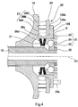
- Fig. 4 is a view showing a toroidal CVT according to Embodiment 2, corresponding to Fig. 3 .
- Embodiment 2 is different from Embodiment 1 in that a cam plate support 128 is configured to contact the cam plate 25 at its curved surface.
- the cam plate support 128 includes an arm portion 128a extending in the radial direction along the back surface 25c of the cam plate 25 in a state in which the arm portion 128a is apart from the back surface 25c in the direction of the rotational axis line A1, and a contact portion 128b provided at a radially outer portion of the arm portion 128a, the contact portion 128b being configured to contact the back surface 25c of the cam plate 25 so that the contact portion 128b can become apart from the back surface 25c.
- a surface of the contact portion 128b, the surface facing the cam plate 25, has a circular-arc surface which is convex toward the cam plate 25, in a cross-sectional view including the rotational axis line A1 and the rollers 26A to 26C.
- a radial position of the apex of the circular-arc surface of the contact portion 28b conforms to a radial position of the center of the roller unit 27.
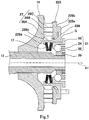
- Fig.5 is a view showing a toroidal CVT according to Embodiment 3, corresponding to Fig. 3 .
- Embodiment 3 is different from Embodiment 1 in that a cam plate support 228 is integrated with a cam plate 225.
- the cam plate 225 has the same shape as that of the cam plate 25 of Embodiment 1.
- the cam plate support 228 includes an arm portion 228a extending in the radial direction along the back surface of the cam plate 225 in a state in which the arm portion 228a is apart from the back surface of the cam plate 225 in the direction of the rotational axis line A1, a coupling portion 228b protruding from the radially outer portion of the arm portion 228a toward the cam plate 225 and secured to the back surface of the cam plate 225, a tubular portion 228c extending along the rotational axis line A1 from the radially inner end portion of the arm portion 228a toward the output disc 14, and a flange portion 228d protruding radially inward, from an end portion of the tubular portion 228c, the end portion being closer to the output disc 14.
- the cam plate 225 and the cam plate support 228 are secured to each other by welding or the like.
- the cam plate 225 and the cam plate support 228 may be formed as a unitary component or fastened to each other by a fastening member.
- the other constituents are the same as those of Embodiment 1, and will not be described in repetition.
- Fig. 6 is a view showing a toroidal CVT according to Embodiment 4, corresponding to Fig. 3 .
- Embodiment 4 is different from Embodiment 1 in that a cam plate support 328 is integrated with an outer race 333 of a thrust bearing 331.
- the cam plate 325 includes an annular plate portion 325a having a cam surface 325d, a tubular portion 325b extending along the rotational axis line A1 from the radially inner end portion of the annular plate portion 325a toward the output disc 14, and a flange portion 325c protruding radially inward from an end portion of the tubular portion 325b, the end portion being closer to the output disc 14.
- the thrust bearing 331 includes an inner race 332, the outer race 333, and rolling elements 334 disposed between the inner race 332 and the outer race 333.
- the outer race 333 is internally fitted to the tubular portion 325b of the cam plate 325.
- the cam plate support 328 includes an arm portion 328a extending in the radial direction along the annular plate portion 325a of the cam plate 325 in a state in which the arm portion 328a is apart from the annular plate portion 325a in the direction of the rotational axis line A1, and a contact portion 328b provided radially outward of the arm portion 328a, the contact portion 328b being configured to contact the back surface of the annular plate portion 325a of the cam plate 325 so that the contact portion 328b can become apart from the back surface of the annular plate portion 325a.
- the cam plate support 328 and the outer race 333 are secured to each other by welding or the like.
- the cam plate support 328 and the outer race 333 may be formed as a unitary component or fastened to each other by a fastening member.
- the other constituents are the same as those of Embodiment 1, and will not be described in repetition.
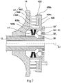
- Fig. 7 is a view showing a toroidal CVT according to Embodiment 5, corresponding to Fig. 3 .
- Embodiment 5 is different from Embodiment 1 in that a cam plate support 428 is integrated with a cam plate 425, and the cam plate support 428 supports the cam plate 425 at a radially outer portion of the cam plate 425.
- the cam plate 425 has the same shape as that of the cam plate 25 of Embodiment 1.
- the cam plate support 428 includes an arm portion 428a extending in the radial direction along the back surface of the cam plate 425 in a state in which the arm portion 428a is apart from the back surface of the cam plate 425 in the direction of the rotational axis line A1, a coupling portion 428b protruding from the radially outer portion of the arm portion 428a toward the cam plate 425 and secured to the back surface of the cam plate 425, a tubular portion 428c extending along the rotational axis line A1 from the radially inner end portion of the arm portion 428a toward the output disc 14, and a flange portion 428d protruding radially inward, from an end portion of the tubular portion 428c, the end portion being closer to the output disc 14.
- the coupling portion 428b is coupled to the back surface of the cam plate 425 at a location that is radially outward of the center portion of the roller unit 27.
- the coupling portion 428b is coupled to the back surface 25c of the cam plate 25 at a location where the coupling portion 428b overlaps with the roller 26c located on a radially outward side, of the three rollers 26A to 26C arranged in the radial direction, when viewed from the direction of the rotational axis line A1.
- the cam plate 425 and the cam plate support 428 are secured to each other by welding or the like.
- the cam plate 425 and the cam plate support 428 may be formed as a unitary component or may be fastened to each other by a fastening member.
Landscapes
- Engineering & Computer Science (AREA)
- General Engineering & Computer Science (AREA)
- Mechanical Engineering (AREA)
- Friction Gearing (AREA)
Claims (6)
- Transmission à variation continue toroïdale (10) comprenant :un premier disque (13) et un second disque (14) disposés de sorte que le premier disque (13) et le second disque (14) soient capables d'une rotation autour d'une ligne axiale de rotation (A1) commune, le premier disque (13) et le second disque (14) étant face à face ;un rouleau motorisé (18) qui est disposé en inclinaison entre le premier disque (13) et le second disque (14) ;un dispositif de pression (20) de type came de chargement, le dispositif de pression (20) comportant une plaque de came (25, 225, 325, 425) qui est capable d'une rotation autour de la ligne axiale de rotation (A1), et une unité à rouleaux (27) comportant au moins un rouleau (26A à 26C) intercalé entre une surface de came du second disque (14) et une surface de came de la plaque de came (25, 225, 325, 425) ;un support de plaque de came (28, 128, 228, 328, 428) supportant une surface arrière (25c) de la plaque de came (25, 225, 325, 425), la surface arrière (25c) étant opposée à la surface de came (25a) de la plaque de came (25, 225, 325, 425), etun ressort précontraint (17) qui sollicite la plaque de came (25, 225, 325, 425) vers l'unité à rouleaux (27) dans une direction de la ligne axiale de rotation (A1),dans laquelle le support de plaque de came (28, 128, 228, 328, 428) est disposé entre la plaque de came (25, 225, 325, 425) et le ressort précontraint (17),caractérisée en ce que :
le support de plaque de came (28, 128, 228, 328, 428) comporte :une portion de bras (28a, 128a, 228a, 328a, 428a) s'étendant dans la direction radiale le long de la surface arrière (25c) de la plaque de came (25, 225, 325, 425) dans un état dans lequel la portion de bras (28a, 128a, 228a, 328a, 428a) est espacée de la surface arrière (25c), etune portion de contact (28b, 128b, 328b) ou une portion de couplage (228b, 428b) prévue au niveau d'une portion radialement externe de la portion de bras (28a) et supportant la surface arrière (25c) de la plaque de came (25, 225, 325, 425) à la position radiale se conformant à la position radiale de la portion de l'unité à rouleaux (27). - Transmission à variation continue toroïdale (10) selon la revendication 1,
dans laquelle le support de plaque de came (28, 128, 228, 328, 428) est séparé de la plaque de came (25, 225, 325, 425), et
dans laquelle la portion de contact (28b, 128b, 328b) est configurée pour entrer en contact avec la surface arrière (25c) de la plaque de came (25, 225, 325, 425) de sorte que la portion de contact (28b, 128b, 328b) puisse s'espacer de la surface arrière (25c) de la plaque de came (25, 225, 325, 425). - Transmission à variation continue toroïdale (10) selon la revendication 1 ou 2, dans laquelle la portion de l'unité à rouleaux (27) est une portion centrale de l'unité à rouleaux (27).
- Transmission à variation continue toroïdale (10) selon l'une quelconque des revendications 1 à 3, dans laquelle une position du ressort précontraint (17) dans la direction de la ligne axiale de rotation (A1) chevauche celles de l'unité à rouleaux (27).
- Transmission à variation continue toroïdale (10) selon l'une quelconque des revendications 1, 3 ou 4, lorsqu'elles ne se réfèrent pas à la revendication 2,
dans laquelle le support de plaque de came (228, 428) est intégré à la plaque de came (225, 425). - Transmission à variation continue toroïdale (10) selon l'une quelconque des revendications 1 à 5, comprenant en outre :un arbre de transmission de force d'entraînement (12) qui est capable d'une rotation conjointement avec le second disque (14),un palier de poussée (331) qui est disposé entre le support de plaque de came (328) et l'arbre de transmission de force d'entraînement (12) dans la direction de la ligne axiale de rotation (A1),dans laquelle le support de plaque de came (328) est intégré à une bague extérieure (333) du palier de poussée (331).
Applications Claiming Priority (2)
| Application Number | Priority Date | Filing Date | Title |
|---|---|---|---|
| JP2016210206A JP6748558B2 (ja) | 2016-10-27 | 2016-10-27 | トロイダル無段変速機 |
| PCT/JP2017/038241 WO2018079505A1 (fr) | 2016-10-27 | 2017-10-24 | Transmission toroïdale à variation continue |
Publications (3)
| Publication Number | Publication Date |
|---|---|
| EP3534036A1 EP3534036A1 (fr) | 2019-09-04 |
| EP3534036A4 EP3534036A4 (fr) | 2020-03-18 |
| EP3534036B1 true EP3534036B1 (fr) | 2021-07-21 |
Family
ID=62024956
Family Applications (1)
| Application Number | Title | Priority Date | Filing Date |
|---|---|---|---|
| EP17866028.8A Active EP3534036B1 (fr) | 2016-10-27 | 2017-10-24 | Transmission toroïdale à variation continue |
Country Status (4)
| Country | Link |
|---|---|
| US (1) | US11067154B2 (fr) |
| EP (1) | EP3534036B1 (fr) |
| JP (1) | JP6748558B2 (fr) |
| WO (1) | WO2018079505A1 (fr) |
Families Citing this family (3)
| Publication number | Priority date | Publication date | Assignee | Title |
|---|---|---|---|---|
| JP6756580B2 (ja) * | 2016-10-27 | 2020-09-16 | 川崎重工業株式会社 | トロイダル無段変速機 |
| JP6748558B2 (ja) * | 2016-10-27 | 2020-09-02 | 川崎重工業株式会社 | トロイダル無段変速機 |
| JP7486341B2 (ja) * | 2020-04-27 | 2024-05-17 | 川崎重工業株式会社 | トロイダル無段変速機 |
Family Cites Families (16)
| Publication number | Priority date | Publication date | Assignee | Title |
|---|---|---|---|---|
| US2292066A (en) * | 1939-11-17 | 1942-08-04 | Richard T Erban | Friction transmission mechanism |
| US3163051A (en) * | 1963-06-19 | 1964-12-29 | Excelermatic | Roller construction for toroidal transmissions |
| JPH0672655B2 (ja) * | 1988-12-16 | 1994-09-14 | 日産自動車株式会社 | トロイダル型無段変速機 |
| JPH0672656B2 (ja) * | 1989-03-31 | 1994-09-14 | 日産自動車株式会社 | トロイダル無段変速機のローディングカム装置 |
| JP4254051B2 (ja) * | 2000-11-15 | 2009-04-15 | 日本精工株式会社 | トロイダル型無段変速機 |
| JP2003028258A (ja) * | 2001-07-19 | 2003-01-29 | Nsk Ltd | トロイダル型無段変速機 |
| JP3775660B2 (ja) * | 2002-01-17 | 2006-05-17 | 日本精工株式会社 | トロイダル型無段変速機のローディングカム装置の保持器 |
| JP2004084913A (ja) * | 2002-08-29 | 2004-03-18 | Nsk Ltd | トロイダル型無段変速機 |
| US7563192B2 (en) * | 2003-06-27 | 2009-07-21 | Nsk Ltd. | Toroidal-type continuously variable transmission |
| JP2005214373A (ja) | 2004-02-02 | 2005-08-11 | Nsk Ltd | トロイダル型無段変速機 |
| US20130035200A1 (en) * | 2011-02-03 | 2013-02-07 | Nsk Ltd | Toroidal continuously variable transmission |
| JP6427899B2 (ja) * | 2013-08-02 | 2018-11-28 | 日本精工株式会社 | トロイダル型無段変速機 |
| JP2015075185A (ja) * | 2013-10-10 | 2015-04-20 | 日本精工株式会社 | シングルキャビティ式トロイダル型無段変速機 |
| WO2015151932A1 (fr) * | 2014-04-02 | 2015-10-08 | 日本精工株式会社 | Transmission variable en continu toroïdale |
| JP6748558B2 (ja) * | 2016-10-27 | 2020-09-02 | 川崎重工業株式会社 | トロイダル無段変速機 |
| JP6756580B2 (ja) * | 2016-10-27 | 2020-09-16 | 川崎重工業株式会社 | トロイダル無段変速機 |
-
2016
- 2016-10-27 JP JP2016210206A patent/JP6748558B2/ja active Active
-
2017
- 2017-10-24 US US16/345,051 patent/US11067154B2/en active Active
- 2017-10-24 EP EP17866028.8A patent/EP3534036B1/fr active Active
- 2017-10-24 WO PCT/JP2017/038241 patent/WO2018079505A1/fr not_active Ceased
Non-Patent Citations (1)
| Title |
|---|
| None * |
Also Published As
| Publication number | Publication date |
|---|---|
| US11067154B2 (en) | 2021-07-20 |
| WO2018079505A1 (fr) | 2018-05-03 |
| JP6748558B2 (ja) | 2020-09-02 |
| US20190277374A1 (en) | 2019-09-12 |
| EP3534036A1 (fr) | 2019-09-04 |
| EP3534036A4 (fr) | 2020-03-18 |
| JP2018071610A (ja) | 2018-05-10 |
Similar Documents
| Publication | Publication Date | Title |
|---|---|---|
| US8956262B2 (en) | Continuously variable transmission | |
| US8961363B2 (en) | Continuously variable transmission | |
| CN100554728C (zh) | 滚动牵引的行星传动 | |
| US8167760B2 (en) | Toroidal continuously variable transmission unit and continuously variable transmission | |
| EP3534036B1 (fr) | Transmission toroïdale à variation continue | |
| US10746267B2 (en) | Toroidal continuously variable transmission | |
| EP2118519B1 (fr) | Entraînement par friction à trois arbres | |
| US12060925B2 (en) | Toroidal continuously variable transmission | |
| EP3109512B1 (fr) | Transmission toroïdale à changement de vitesses continu | |
| EP3441644B1 (fr) | Transmission toroïdale à variation continue | |
| JP2002276749A (ja) | 電動式駆動装置 | |
| EP4636280A1 (fr) | Transmission toroïdale à variation continue | |
| JP7449769B2 (ja) | トロイダル無段変速機 | |
| EP2199633B1 (fr) | Structure de support d'arbre d'entrée | |
| US6945904B2 (en) | Toroidal-type continuously variable transmission | |
| JP2025099042A (ja) | トロイダル型無段変速機 | |
| JP6421462B2 (ja) | トロイダル型無段変速機 | |
| JPS62215160A (ja) | 牽引ロ−ラ変速機 | |
| JP2002340119A (ja) | トロイダル型無段変速機 | |
| JP2000018354A (ja) | トロイダル型無段変速機 |
Legal Events
| Date | Code | Title | Description |
|---|---|---|---|
| STAA | Information on the status of an ep patent application or granted ep patent |
Free format text: STATUS: THE INTERNATIONAL PUBLICATION HAS BEEN MADE |
|
| PUAI | Public reference made under article 153(3) epc to a published international application that has entered the european phase |
Free format text: ORIGINAL CODE: 0009012 |
|
| STAA | Information on the status of an ep patent application or granted ep patent |
Free format text: STATUS: REQUEST FOR EXAMINATION WAS MADE |
|
| 17P | Request for examination filed |
Effective date: 20190517 |
|
| AK | Designated contracting states |
Kind code of ref document: A1 Designated state(s): AL AT BE BG CH CY CZ DE DK EE ES FI FR GB GR HR HU IE IS IT LI LT LU LV MC MK MT NL NO PL PT RO RS SE SI SK SM TR |
|
| AX | Request for extension of the european patent |
Extension state: BA ME |
|
| DAV | Request for validation of the european patent (deleted) | ||
| DAX | Request for extension of the european patent (deleted) | ||
| A4 | Supplementary search report drawn up and despatched |
Effective date: 20200213 |
|
| RIC1 | Information provided on ipc code assigned before grant |
Ipc: F16H 15/38 20060101AFI20200207BHEP |
|
| RIC1 | Information provided on ipc code assigned before grant |
Ipc: F16H 15/38 20060101AFI20201012BHEP Ipc: F16H 13/14 20060101ALI20201012BHEP |
|
| GRAP | Despatch of communication of intention to grant a patent |
Free format text: ORIGINAL CODE: EPIDOSNIGR1 |
|
| STAA | Information on the status of an ep patent application or granted ep patent |
Free format text: STATUS: GRANT OF PATENT IS INTENDED |
|
| INTG | Intention to grant announced |
Effective date: 20210218 |
|
| GRAS | Grant fee paid |
Free format text: ORIGINAL CODE: EPIDOSNIGR3 |
|
| GRAA | (expected) grant |
Free format text: ORIGINAL CODE: 0009210 |
|
| STAA | Information on the status of an ep patent application or granted ep patent |
Free format text: STATUS: THE PATENT HAS BEEN GRANTED |
|
| AK | Designated contracting states |
Kind code of ref document: B1 Designated state(s): AL AT BE BG CH CY CZ DE DK EE ES FI FR GB GR HR HU IE IS IT LI LT LU LV MC MK MT NL NO PL PT RO RS SE SI SK SM TR |
|
| REG | Reference to a national code |
Ref country code: GB Ref legal event code: FG4D |
|
| REG | Reference to a national code |
Ref country code: CH Ref legal event code: EP |
|
| REG | Reference to a national code |
Ref country code: DE Ref legal event code: R096 Ref document number: 602017042695 Country of ref document: DE |
|
| REG | Reference to a national code |
Ref country code: AT Ref legal event code: REF Ref document number: 1412881 Country of ref document: AT Kind code of ref document: T Effective date: 20210815 |
|
| REG | Reference to a national code |
Ref country code: IE Ref legal event code: FG4D |
|
| REG | Reference to a national code |
Ref country code: LT Ref legal event code: MG9D |
|
| REG | Reference to a national code |
Ref country code: NL Ref legal event code: MP Effective date: 20210721 |
|
| REG | Reference to a national code |
Ref country code: AT Ref legal event code: MK05 Ref document number: 1412881 Country of ref document: AT Kind code of ref document: T Effective date: 20210721 |
|
| PG25 | Lapsed in a contracting state [announced via postgrant information from national office to epo] |
Ref country code: NO Free format text: LAPSE BECAUSE OF FAILURE TO SUBMIT A TRANSLATION OF THE DESCRIPTION OR TO PAY THE FEE WITHIN THE PRESCRIBED TIME-LIMIT Effective date: 20211021 Ref country code: PT Free format text: LAPSE BECAUSE OF FAILURE TO SUBMIT A TRANSLATION OF THE DESCRIPTION OR TO PAY THE FEE WITHIN THE PRESCRIBED TIME-LIMIT Effective date: 20211122 Ref country code: NL Free format text: LAPSE BECAUSE OF FAILURE TO SUBMIT A TRANSLATION OF THE DESCRIPTION OR TO PAY THE FEE WITHIN THE PRESCRIBED TIME-LIMIT Effective date: 20210721 Ref country code: BG Free format text: LAPSE BECAUSE OF FAILURE TO SUBMIT A TRANSLATION OF THE DESCRIPTION OR TO PAY THE FEE WITHIN THE PRESCRIBED TIME-LIMIT Effective date: 20211021 Ref country code: AT Free format text: LAPSE BECAUSE OF FAILURE TO SUBMIT A TRANSLATION OF THE DESCRIPTION OR TO PAY THE FEE WITHIN THE PRESCRIBED TIME-LIMIT Effective date: 20210721 Ref country code: LT Free format text: LAPSE BECAUSE OF FAILURE TO SUBMIT A TRANSLATION OF THE DESCRIPTION OR TO PAY THE FEE WITHIN THE PRESCRIBED TIME-LIMIT Effective date: 20210721 Ref country code: FI Free format text: LAPSE BECAUSE OF FAILURE TO SUBMIT A TRANSLATION OF THE DESCRIPTION OR TO PAY THE FEE WITHIN THE PRESCRIBED TIME-LIMIT Effective date: 20210721 Ref country code: ES Free format text: LAPSE BECAUSE OF FAILURE TO SUBMIT A TRANSLATION OF THE DESCRIPTION OR TO PAY THE FEE WITHIN THE PRESCRIBED TIME-LIMIT Effective date: 20210721 Ref country code: HR Free format text: LAPSE BECAUSE OF FAILURE TO SUBMIT A TRANSLATION OF THE DESCRIPTION OR TO PAY THE FEE WITHIN THE PRESCRIBED TIME-LIMIT Effective date: 20210721 Ref country code: SE Free format text: LAPSE BECAUSE OF FAILURE TO SUBMIT A TRANSLATION OF THE DESCRIPTION OR TO PAY THE FEE WITHIN THE PRESCRIBED TIME-LIMIT Effective date: 20210721 Ref country code: RS Free format text: LAPSE BECAUSE OF FAILURE TO SUBMIT A TRANSLATION OF THE DESCRIPTION OR TO PAY THE FEE WITHIN THE PRESCRIBED TIME-LIMIT Effective date: 20210721 |
|
| PG25 | Lapsed in a contracting state [announced via postgrant information from national office to epo] |
Ref country code: PL Free format text: LAPSE BECAUSE OF FAILURE TO SUBMIT A TRANSLATION OF THE DESCRIPTION OR TO PAY THE FEE WITHIN THE PRESCRIBED TIME-LIMIT Effective date: 20210721 Ref country code: LV Free format text: LAPSE BECAUSE OF FAILURE TO SUBMIT A TRANSLATION OF THE DESCRIPTION OR TO PAY THE FEE WITHIN THE PRESCRIBED TIME-LIMIT Effective date: 20210721 Ref country code: GR Free format text: LAPSE BECAUSE OF FAILURE TO SUBMIT A TRANSLATION OF THE DESCRIPTION OR TO PAY THE FEE WITHIN THE PRESCRIBED TIME-LIMIT Effective date: 20211022 |
|
| REG | Reference to a national code |
Ref country code: DE Ref legal event code: R097 Ref document number: 602017042695 Country of ref document: DE |
|
| PG25 | Lapsed in a contracting state [announced via postgrant information from national office to epo] |
Ref country code: DK Free format text: LAPSE BECAUSE OF FAILURE TO SUBMIT A TRANSLATION OF THE DESCRIPTION OR TO PAY THE FEE WITHIN THE PRESCRIBED TIME-LIMIT Effective date: 20210721 |
|
| PLBE | No opposition filed within time limit |
Free format text: ORIGINAL CODE: 0009261 |
|
| STAA | Information on the status of an ep patent application or granted ep patent |
Free format text: STATUS: NO OPPOSITION FILED WITHIN TIME LIMIT |
|
| REG | Reference to a national code |
Ref country code: CH Ref legal event code: PL |
|
| PG25 | Lapsed in a contracting state [announced via postgrant information from national office to epo] |
Ref country code: SM Free format text: LAPSE BECAUSE OF FAILURE TO SUBMIT A TRANSLATION OF THE DESCRIPTION OR TO PAY THE FEE WITHIN THE PRESCRIBED TIME-LIMIT Effective date: 20210721 Ref country code: SK Free format text: LAPSE BECAUSE OF FAILURE TO SUBMIT A TRANSLATION OF THE DESCRIPTION OR TO PAY THE FEE WITHIN THE PRESCRIBED TIME-LIMIT Effective date: 20210721 Ref country code: RO Free format text: LAPSE BECAUSE OF FAILURE TO SUBMIT A TRANSLATION OF THE DESCRIPTION OR TO PAY THE FEE WITHIN THE PRESCRIBED TIME-LIMIT Effective date: 20210721 Ref country code: EE Free format text: LAPSE BECAUSE OF FAILURE TO SUBMIT A TRANSLATION OF THE DESCRIPTION OR TO PAY THE FEE WITHIN THE PRESCRIBED TIME-LIMIT Effective date: 20210721 Ref country code: CZ Free format text: LAPSE BECAUSE OF FAILURE TO SUBMIT A TRANSLATION OF THE DESCRIPTION OR TO PAY THE FEE WITHIN THE PRESCRIBED TIME-LIMIT Effective date: 20210721 Ref country code: AL Free format text: LAPSE BECAUSE OF FAILURE TO SUBMIT A TRANSLATION OF THE DESCRIPTION OR TO PAY THE FEE WITHIN THE PRESCRIBED TIME-LIMIT Effective date: 20210721 |
|
| REG | Reference to a national code |
Ref country code: BE Ref legal event code: MM Effective date: 20211031 |
|
| 26N | No opposition filed |
Effective date: 20220422 |
|
| PG25 | Lapsed in a contracting state [announced via postgrant information from national office to epo] |
Ref country code: MC Free format text: LAPSE BECAUSE OF FAILURE TO SUBMIT A TRANSLATION OF THE DESCRIPTION OR TO PAY THE FEE WITHIN THE PRESCRIBED TIME-LIMIT Effective date: 20210721 |
|
| PG25 | Lapsed in a contracting state [announced via postgrant information from national office to epo] |
Ref country code: LU Free format text: LAPSE BECAUSE OF NON-PAYMENT OF DUE FEES Effective date: 20211024 Ref country code: IT Free format text: LAPSE BECAUSE OF FAILURE TO SUBMIT A TRANSLATION OF THE DESCRIPTION OR TO PAY THE FEE WITHIN THE PRESCRIBED TIME-LIMIT Effective date: 20210721 Ref country code: BE Free format text: LAPSE BECAUSE OF NON-PAYMENT OF DUE FEES Effective date: 20211031 |
|
| PG25 | Lapsed in a contracting state [announced via postgrant information from national office to epo] |
Ref country code: LI Free format text: LAPSE BECAUSE OF NON-PAYMENT OF DUE FEES Effective date: 20211031 Ref country code: CH Free format text: LAPSE BECAUSE OF NON-PAYMENT OF DUE FEES Effective date: 20211031 |
|
| PG25 | Lapsed in a contracting state [announced via postgrant information from national office to epo] |
Ref country code: IE Free format text: LAPSE BECAUSE OF NON-PAYMENT OF DUE FEES Effective date: 20211024 |
|
| PG25 | Lapsed in a contracting state [announced via postgrant information from national office to epo] |
Ref country code: CY Free format text: LAPSE BECAUSE OF FAILURE TO SUBMIT A TRANSLATION OF THE DESCRIPTION OR TO PAY THE FEE WITHIN THE PRESCRIBED TIME-LIMIT Effective date: 20210721 |
|
| PG25 | Lapsed in a contracting state [announced via postgrant information from national office to epo] |
Ref country code: HU Free format text: LAPSE BECAUSE OF FAILURE TO SUBMIT A TRANSLATION OF THE DESCRIPTION OR TO PAY THE FEE WITHIN THE PRESCRIBED TIME-LIMIT; INVALID AB INITIO Effective date: 20171024 |
|
| PG25 | Lapsed in a contracting state [announced via postgrant information from national office to epo] |
Ref country code: MK Free format text: LAPSE BECAUSE OF FAILURE TO SUBMIT A TRANSLATION OF THE DESCRIPTION OR TO PAY THE FEE WITHIN THE PRESCRIBED TIME-LIMIT Effective date: 20210721 |
|
| PG25 | Lapsed in a contracting state [announced via postgrant information from national office to epo] |
Ref country code: TR Free format text: LAPSE BECAUSE OF FAILURE TO SUBMIT A TRANSLATION OF THE DESCRIPTION OR TO PAY THE FEE WITHIN THE PRESCRIBED TIME-LIMIT Effective date: 20210721 |
|
| PG25 | Lapsed in a contracting state [announced via postgrant information from national office to epo] |
Ref country code: MT Free format text: LAPSE BECAUSE OF FAILURE TO SUBMIT A TRANSLATION OF THE DESCRIPTION OR TO PAY THE FEE WITHIN THE PRESCRIBED TIME-LIMIT Effective date: 20210721 |
|
| PGFP | Annual fee paid to national office [announced via postgrant information from national office to epo] |
Ref country code: GB Payment date: 20250904 Year of fee payment: 9 |
|
| PGFP | Annual fee paid to national office [announced via postgrant information from national office to epo] |
Ref country code: FR Payment date: 20250908 Year of fee payment: 9 |
|
| PGFP | Annual fee paid to national office [announced via postgrant information from national office to epo] |
Ref country code: DE Payment date: 20250902 Year of fee payment: 9 |