EP3534360A1 - Schalldämmende beschichtung, die eine wabenstruktur mit gekrümmten zellen umfasst, die auf der einen und der anderen seite aus derselben innenwand gebildet werden - Google Patents
Schalldämmende beschichtung, die eine wabenstruktur mit gekrümmten zellen umfasst, die auf der einen und der anderen seite aus derselben innenwand gebildet werden Download PDFInfo
- Publication number
- EP3534360A1 EP3534360A1 EP19157493.8A EP19157493A EP3534360A1 EP 3534360 A1 EP3534360 A1 EP 3534360A1 EP 19157493 A EP19157493 A EP 19157493A EP 3534360 A1 EP3534360 A1 EP 3534360A1
- Authority
- EP
- European Patent Office
- Prior art keywords
- face
- cell
- wall
- coating
- duct
- Prior art date
- Legal status (The legal status is an assumption and is not a legal conclusion. Google has not performed a legal analysis and makes no representation as to the accuracy of the status listed.)
- Granted
Links
Images


Classifications
-
- F—MECHANICAL ENGINEERING; LIGHTING; HEATING; WEAPONS; BLASTING
- F02—COMBUSTION ENGINES; HOT-GAS OR COMBUSTION-PRODUCT ENGINE PLANTS
- F02K—JET-PROPULSION PLANTS
- F02K1/00—Plants characterised by the form or arrangement of the jet pipe or nozzle; Jet pipes or nozzles peculiar thereto
- F02K1/78—Other construction of jet pipes
- F02K1/82—Jet pipe walls, e.g. liners
- F02K1/827—Sound absorbing structures or liners
-
- B—PERFORMING OPERATIONS; TRANSPORTING
- B64—AIRCRAFT; AVIATION; COSMONAUTICS
- B64C—AEROPLANES; HELICOPTERS
- B64C1/00—Fuselages; Constructional features common to fuselages, wings, stabilising surfaces or the like
- B64C1/40—Sound or heat insulation, e.g. using insulation blankets
-
- F—MECHANICAL ENGINEERING; LIGHTING; HEATING; WEAPONS; BLASTING
- F02—COMBUSTION ENGINES; HOT-GAS OR COMBUSTION-PRODUCT ENGINE PLANTS
- F02C—GAS-TURBINE PLANTS; AIR INTAKES FOR JET-PROPULSION PLANTS; CONTROLLING FUEL SUPPLY IN AIR-BREATHING JET-PROPULSION PLANTS
- F02C7/00—Features, components parts, details or accessories, not provided for in, or of interest apart form groups F02C1/00 - F02C6/00; Air intakes for jet-propulsion plants
- F02C7/04—Air intakes for gas-turbine plants or jet-propulsion plants
- F02C7/045—Air intakes for gas-turbine plants or jet-propulsion plants having provisions for noise suppression
-
- F—MECHANICAL ENGINEERING; LIGHTING; HEATING; WEAPONS; BLASTING
- F02—COMBUSTION ENGINES; HOT-GAS OR COMBUSTION-PRODUCT ENGINE PLANTS
- F02C—GAS-TURBINE PLANTS; AIR INTAKES FOR JET-PROPULSION PLANTS; CONTROLLING FUEL SUPPLY IN AIR-BREATHING JET-PROPULSION PLANTS
- F02C7/00—Features, components parts, details or accessories, not provided for in, or of interest apart form groups F02C1/00 - F02C6/00; Air intakes for jet-propulsion plants
- F02C7/24—Heat or noise insulation
-
- B—PERFORMING OPERATIONS; TRANSPORTING
- B64—AIRCRAFT; AVIATION; COSMONAUTICS
- B64D—EQUIPMENT FOR FITTING IN OR TO AIRCRAFT; FLIGHT SUITS; PARACHUTES; ARRANGEMENT OR MOUNTING OF POWER PLANTS OR PROPULSION TRANSMISSIONS IN AIRCRAFT
- B64D33/00—Arrangement in aircraft of power plant parts or auxiliaries not otherwise provided for
- B64D33/02—Arrangement in aircraft of power plant parts or auxiliaries not otherwise provided for of combustion air intakes
- B64D2033/0206—Arrangement in aircraft of power plant parts or auxiliaries not otherwise provided for of combustion air intakes comprising noise reduction means, e.g. acoustic liners
-
- F—MECHANICAL ENGINEERING; LIGHTING; HEATING; WEAPONS; BLASTING
- F05—INDEXING SCHEMES RELATING TO ENGINES OR PUMPS IN VARIOUS SUBCLASSES OF CLASSES F01-F04
- F05D—INDEXING SCHEME FOR ASPECTS RELATING TO NON-POSITIVE-DISPLACEMENT MACHINES OR ENGINES, GAS-TURBINES OR JET-PROPULSION PLANTS
- F05D2250/00—Geometry
- F05D2250/20—Three-dimensional
- F05D2250/28—Three-dimensional patterned
- F05D2250/283—Three-dimensional patterned honeycomb
-
- F—MECHANICAL ENGINEERING; LIGHTING; HEATING; WEAPONS; BLASTING
- F05—INDEXING SCHEMES RELATING TO ENGINES OR PUMPS IN VARIOUS SUBCLASSES OF CLASSES F01-F04
- F05D—INDEXING SCHEME FOR ASPECTS RELATING TO NON-POSITIVE-DISPLACEMENT MACHINES OR ENGINES, GAS-TURBINES OR JET-PROPULSION PLANTS
- F05D2250/00—Geometry
- F05D2250/70—Shape
- F05D2250/75—Shape given by its similarity to a letter, e.g. T-shaped
-
- F—MECHANICAL ENGINEERING; LIGHTING; HEATING; WEAPONS; BLASTING
- F05—INDEXING SCHEMES RELATING TO ENGINES OR PUMPS IN VARIOUS SUBCLASSES OF CLASSES F01-F04
- F05D—INDEXING SCHEME FOR ASPECTS RELATING TO NON-POSITIVE-DISPLACEMENT MACHINES OR ENGINES, GAS-TURBINES OR JET-PROPULSION PLANTS
- F05D2260/00—Function
- F05D2260/96—Preventing, counteracting or reducing vibration or noise
- F05D2260/963—Preventing, counteracting or reducing vibration or noise by Helmholtz resonators
-
- G—PHYSICS
- G10—MUSICAL INSTRUMENTS; ACOUSTICS
- G10K—SOUND-PRODUCING DEVICES; METHODS OR DEVICES FOR PROTECTING AGAINST, OR FOR DAMPING, NOISE OR OTHER ACOUSTIC WAVES IN GENERAL; ACOUSTICS NOT OTHERWISE PROVIDED FOR
- G10K11/00—Methods or devices for transmitting, conducting or directing sound in general; Methods or devices for protecting against, or for damping, noise or other acoustic waves in general
- G10K11/16—Methods or devices for protecting against, or for damping, noise or other acoustic waves in general
- G10K11/172—Methods or devices for protecting against, or for damping, noise or other acoustic waves in general using resonance effects
-
- Y—GENERAL TAGGING OF NEW TECHNOLOGICAL DEVELOPMENTS; GENERAL TAGGING OF CROSS-SECTIONAL TECHNOLOGIES SPANNING OVER SEVERAL SECTIONS OF THE IPC; TECHNICAL SUBJECTS COVERED BY FORMER USPC CROSS-REFERENCE ART COLLECTIONS [XRACs] AND DIGESTS
- Y02—TECHNOLOGIES OR APPLICATIONS FOR MITIGATION OR ADAPTATION AGAINST CLIMATE CHANGE
- Y02T—CLIMATE CHANGE MITIGATION TECHNOLOGIES RELATED TO TRANSPORTATION
- Y02T50/00—Aeronautics or air transport
- Y02T50/60—Efficient propulsion technologies, e.g. for aircraft
Definitions
- the present invention relates to the field of soundproofing structures.
- the coating object of the invention may have applications, in particular in the aeronautical field, for example in nacelles of aircraft powertrains.
- Coatings or panels comprising a honeycomb structure consisting of cells or cells, that is to say of juxtaposed hollow unit volumes, are used in many technical fields, particularly in the aeronautical field. They can have high rigidity for a low mass. Coatings having a honeycomb structure having cells open on one side, or at the very least cells communicating with the outside of the panel are employed for their soundproofing properties. Such panels are sometimes called acoustic panels.
- honeycombed panels or coatings may be formed of various materials, for example plastics, composites, or metals.
- the cells may have various geometries.
- a well-known form of honeycomb structure has cells in the form of hexagonal base right prism. It is often referred to as a "honeycomb" structure for this type of hexagonal cell structure, but this expression is also used as a misnomer for alveolar panels with other cell shapes.
- the cells of acoustic panels act as small resonators allowing the absorption of acoustic waves over a given frequency range.
- its absorption frequency range must include the frequency with which the panel is subjected.
- the relatively small cavities of the acoustic panels correspond to high frequencies. It is thus difficult to obtain an efficient honeycomb panel for certain applications subjected to low frequencies.
- the powertrains of commercial aircraft comprise a turbomachine engine and a nacelle that may include an acoustic coating to attenuate the noise generated during operation of the engine.
- the acoustic frequencies generated by the engine of an aircraft are relatively low and extend over a fairly wide range.
- the low frequencies to be attenuated are for example the frequencies below 2000 Hz depending on the engine considered.
- the adoption of large diameter powertrains tends to further reduce the frequencies of the acoustic waves they generate.
- the need to have high volume cells to absorb low frequencies leads to thick panels, not very compatible with an aeronautical application.
- the invention aims to provide a soundproofing coating with honeycomb structure, improved so that it allows soundproofing on low frequencies and a wide frequency range, compared to known coatings in the state of the art, constant thickness and comparable mass.
- the invention relates to a soundproofing coating comprising a honeycomb structure, the coating having a first face and a second face, said cellular structure being formed of cells open on said first face and closed on said second face, said cells being juxtaposed in a first direction said longitudinal and in a second direction said transverse and which is orthogonal to the longitudinal direction.
- Each cell comprises a duct extending at least between the first face and the second face, said duct being formed between an outer wall and an inner wall of the cell and having a restriction of its section.
- the outer wall and the inner wall have rounded shapes, devoid of edges.
- Each cell has a cavity into which said conduit opens.
- the cell forms a resonator comprising a neck formed by said duct, and said cavity.
- the cell is shaped so that the conduit and the cavity are formed on either side of the inner wall.
- Each cell of the coating may have a substantially volute section in a longitudinal sectional plane perpendicular to the transverse direction.
- the inner wall of a cell of the lining and the outer wall of an adjacent cell may join together to form only a transverse wall separating said cell from said adjacent cell at the level of the first face. There is thus no loss of acoustic surface between the cells.
- the inner wall of a cell of the coating and the outer wall of an adjacent cell can meet at the first face in forming between them an acute angle so as to form a transverse edge at said first face.
- the transverse wall separating said cell from said adjacent cell at the level of the first face is therefore limited in this case to this single transverse edge. This configuration promotes the entry of acoustic waves into the cells of the coating.
- the first conduit portion may be substantially symmetrical in a transverse plane perpendicular to the first face.
- the outer and inner walls may advantageously have rounded shapes, devoid of stops.
- the conduit of the cell forming the neck of the resonator and the cavity are for example dimensioned so that the resonance frequency of said resonator is less than 2000Hz.
- the first face may comprise a resistive sheet allowing the cells of the coating to communicate with the outside of said coating.
- each cell may have a perforation fluidly binding the neck to the cavity of the resonator.
- the invention also relates to an aircraft propulsion unit comprising a nacelle and a motor, wherein an inner surface of the nacelle and / or an outer surface of a motor housing has a sound-absorbing coating as previously described.
- a panel soundproofing is generally intended to be affixed to a carrier element, and is in this sense a coating.
- a panel is not limited to a flat geometry.
- a soundproofing coating comprising a honeycomb structure is formed of a panel, which may be affixed to a carrier member, and has or not flexibility to be shaped on said carrier member.
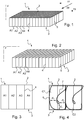
- the figure 1 schematically represents a soundproofing coating known in the state of the art. It contains cells A1, A2, A3, A4, etc. juxtaposed to each other in two directions orthogonal to each other so as to form a honeycomb structure. Arbitrarily, a first direction D1 of juxtaposition of the cells is said to be longitudinal, and a second direction D2 of juxtaposition of the cells, orthogonal to the first direction D1, is said to be transversal. A third direction D3 is defined orthogonally to the first direction D1 and second direction D2.
- cells A1 ... A4 are open.
- a perforated sheet 2 covers them, allowing the communication of cells A1 ... A4 with the external medium.
- the cells A1 ... A4 are closed for example by a solid sheet obstructing the bottom of the cells.
- the soundproofing coating of the figure 1 is represented on the figure 2 without the perforated sheet 2.
- the cells of the cellular structure shown here are said to be square, in that their volume is that of a right square base prism extending between the first face 1 and the second face 3 of the soundproofing coating.
- the cells are juxtaposed so as to form a regular grid.
- each cell is adjacent to two cells longitudinally and two cells transversely, with the obvious exception of cells located on the edges of the coating.
- the figure 3 represents four cells A1 ... A4 of the honeycomb structures of sound-absorbing coatings represented in Figures 1 and 2 , according to the longitudinal plane of section P shown in FIGS. Figures 1 and 2 .
- the cutting plane P longitudinally crosses the cells of the sound-absorbing coating, and is orthogonal to the first face 1 and the second face 3 in the case of a coating or flat panel.
- Each cell is separated from adjacent cells by a transverse wall 4 which is straight and which connects the first face 1 and the second face 3 orthogonally to the latter.
- longitudinal walls separate the cells in a similar manner.
- FIG. 4 to 15 represent all or part of a soundproofing coating according to various embodiments of the invention, given by way of examples.
- Figures 4 to 14 represent sectional views of cells according to various embodiments of the invention, according to a sectional plane similar to the section plane of the figure 3 .
- the cuts of the cells of the soundproofing coatings according to the invention are represented (in strong lines) in superimpression of the section of the cells of the conventional structure of the Figures 1 to 3 (in fine lines).
- the figure 4 represents two cells C1, C2 of a sound-absorbing coating according to one embodiment of the invention.
- each cell of the honeycomb structure has a section, according to the sectional plane P, defined by an outer wall 6 and an inner wall 7.
- the outer wall 6 and the inner wall 7 form a duct.
- This conduit opens into a closed cavity.
- each cell forms a resonator, similar to a Helmholtz resonator, whose neck is formed by the conduit.
- the duct is curved, so that said duct and said cavity are formed on either side of the inner wall 7.
- the cell can thus have, as is the case in the embodiments presented to the Figures 4 to 13 , a general shape in volute.
- a volute corresponds to a shape, two-dimensional, approximately spiral.
- each cell of the embodiment shown in FIG. figure 4 in the longitudinal direction substantially the same dimension as two cells according to the state of the art shown in figure 3 .
- each cell C1, C2 is open, and has an open surface substantially corresponding to the open surface of two cells according to the state of the art shown in FIG. figure 3 .
- the honeycomb structure has longitudinal walls 5 similar to those of the state of the art shown in FIGS. Figures 1 to 3 .
- the outer wall 6 and the inner wall 7 are orthogonal to the longitudinal walls 5.
- the passage section or surface of this duct presents, starting from the open face of the cell and while moving towards the bottom of said cell, a narrowing (forming a restriction of the passage section of the conduit).
- the duct of the cell C1, C2 comprises a first portion of duct extending from the open face of the cell (at the level of the first face 1 of the sound-absorbing coating) towards the second face 3 of the sound-absorbing coating, followed by a second curved portion, forming in this embodiment an angle of 180 ° between the direction of the duct at its inlet and the direction of the duct at its outlet, in the section plane P. in other words, the duct forms at the level of the second portion a half-turn before opening into the cavity of the cell.
- the second portion opens into a cavity, that is to say a closed volume of enlarged section.
- the narrowing of the duct may be continuous, progressive or not, and extend over the first duct portion or on the first and second duct portion.
- the cell may thus have a dimension at the inlet of the conduit which forms it, measured between the outer wall 6 and the inner wall 7 at the open face of the cell, which is greater than a first dimension d1 measured, in the first direction D1, between the outer wall 6 and the inner wall 7 at the boundary between the first portion and the second portion.
- the first dimension d1 may be greater than a second dimension d2 measured, in the third direction D3, between the outer wall 6 and the inner wall 7 at the curved portion where the duct is parallel and tangential to the second face 3 of the coating .
- the second dimension d2 is thus measured at the level where the duct has formed a curve rotating at 90 ° in the plane of section P relative to the general direction of the first portion of the duct, namely the third direction D3.
- the duct is thus oriented in the first direction D1 at the level where the second dimension d2 is measured.
- the second dimension d2 may be greater than a third dimension d3, measured in the first direction D1 between the outer wall 6 and the inner wall 7 at the entrance of the cavity.
- the passage section of the duct is rectangular, and the surface of this passage section is proportional to the distance between the outer wall 6 and the inner wall 7.
- FIG 5 illustrates the principle implemented in the invention. Left on the figure 5 , is shown, in section and very schematically, a Helmholtz resonator as known in the state of the art.
- a Helmholtz resonator comprises a closed cavity 8 of volume V which communicates with the outside via a small tube of length L and section A, called collar 9.
- each cell forms a pseudo Helmholtz resonator whose neck is formed by the conduit from the entrance of the cell and a cavity in which the conduit opens.
- the neck of the cell is shown hatched, while the cavity is represented by a dashed texture.
- the length L of the neck formed in the invention by the conduit of the cell is very strongly increased, which lowers the natural frequency of the resonator.
- the figure 6 presents in particular two cells C1, C2 of a soundproofing coating according to one embodiment of the invention in which the geometry of the cell, seen in section along the sectional plane P, is based on an ellipse 10 shown in fine lines .
- the outer wall 6 seen in the plane of section P follows the outline of the ellipse 10 on one or more portions of said ellipse 10, in particular at least partially (and in the example here totally represented) on a connecting portion the first face 1 to the second face 3.
- the figure 7 presents two cells C1, C2 of a soundproofing coating according to an embodiment of the invention in which the geometry of the cell, seen in section along the sectional plane P, is based on a circle 11 shown in fine lines.
- the outer wall 6, seen in the section plane P follows the pattern of the circle 11 at least partially on a portion connecting the first face 1 to the second face 3.
- the figure 8 represents four cells C1 ... C4 of a soundproofing coating according to one embodiment of the invention.
- This embodiment has the particularity that the first portion of the duct, between the entrance of the cell and the beginning of the second curved portion has symmetry or quasi-symmetry along a plane of symmetry P2 orthogonal to the section plane P and the first face 1 of the coating. This apparent symmetry allows a treatment with almost symmetrical acoustic behavior.
- the figure 9 represents four cells C1 ... C4 of a soundproofing coating according to one embodiment of the invention having as the coating of the figure 8 cells having a conduit whose first portion is symmetrical or quasi-symmetrical along the plane P2. It has in particular a section, in the section plane P, substantially in "V".
- the outer wall 6 In the second portion of the duct, forming a curve rotating at 180 ° (relative to the general direction of the first portion in "V", namely the third direction D3), the outer wall 6 at least partially follows a construction circle 12.
- this second portion of the inner wall 7 also extends in an arc of a circle, substantially parallel to the outer wall 6, it follows that the dimensions d1, d2 and d3 are substantially equal in this mode of operation. production.
- This geometry has a very narrow neck and very long, allowing a significant acoustic reduction on low frequencies.
- a perforation 13 may be provided for this purpose in all the embodiments of the invention, and in particular in the embodiments described with reference to Figures 4 to 14 .
- the figure 11 represents three cells C1 ... C3 of a soundproofing coating according to one embodiment of the invention.
- the configuration of the duct is similar to that of the cells of the coating of the figure 9 , the duct being in its first symmetrical or quasi-symmetrical portion along the plane P2.
- the second portion of the duct is curved and is shaped so that the direction of the duct at its outlet is oriented 180 ° relative to the general direction of the first portion in "V", namely the third direction D3.
- the general geometry of the cell is however enlarged compared to the cells of the embodiment of the figure 9 .
- the opening of the cell on the first face 1 is strongly flared, the "V" formed by the first portion of the conduit being more open, and the neck of the resonator formed by the conduit being elongated.
- the volume of the cavity is increased. Lower frequencies can thus be processed. Nevertheless, the number of cells per square meter of coating is decreased, and the mechanical characteristics of the coating can be decreased.
- the figure 12 represents three cells C1 ... C3 of a soundproofing coating according to one embodiment of the invention.
- the configuration of the duct is similar to that of the cells of the coating of the figure 11 , the duct being in its first symmetrical or quasi-symmetrical portion along the plane P2.
- the second portion of the duct forms a curve rotating at 180 ° or almost 180 ° (in this case of the order of 160 °).
- the first portion of the duct is shortened, which lengthens the second portion but especially increases the volume of the cavity of the resonator. Lower frequencies can thus be treated, but the first portion of the conduit is shaped "V" shorter, which increases the acoustic resistance of the cell.
- the figure 13 represents five cells C1 ... C5 of a soundproofing coating according to one embodiment of the invention.
- the second portion of the conduit forms between the direction of the conduit at its entrance and the direction of the conduit a curve rotating at 90 ° in the cutting plane P before opening into the cavity of the resonator.
- the second portion opens into the cavity in a direction orthogonal to its direction of entry.
- the first portion of the duct extending substantially in the third direction D3, the entrance into the cavity is substantially in the second direction D2.
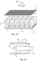
- the figure 14 represents a three-dimensional view of the embodiment of the figure 8 .
- the cells of the coating are separated from each other in the transverse direction D2 by longitudinal walls 5 parallel to each other.
- the outer and inner walls 6 of the cells 7 extend perpendicularly to the longitudinal walls 5.
- a perforated plate 2, here shown exploded with respect to the rest of the soundproofing coating forms the first face 1 of said soundproofing coating.
- the first face of the soundproofing coating may advantageously comprise a resistive layer, namely by a perforated sheet 2 on the side of the inlet of the neck (for example similar to the perforated sheets used in the state of the art) or wire mesh (sometimes referred to as "wiremesh").
- the sound-absorbing coating comprises a solid sheet 14 embodying said second face 3 and offering good mechanical cohesion to the soundproofing coating, and, where appropriate, closing the cells on the second face 3.
- the coating having cells whose open face is square or rectangular, it has good efficiency for flows in both the longitudinal direction D1 and the transverse direction D2.
- the inner wall 7 of a cell and the outer wall 6 of a longitudinally adjacent cell joining so as to form only one wall transversely at the level of the first face 1, there is no loss of acoustic surface at said first face 1.
- the transverse wall visible between two cells at the first face 1 is limited to a folding edge or junction between the inner wall 7 of a cell and the outer wall 6 of an adjacent cell.
- the inner wall 7 of a cell of the coating and the outer wall 6 of an adjacent cell meet at the first face 1.
- the inner wall 7 and the outer wall 6 of an adjacent cell form between them an acute angle, that is to say an angle less than 90 °, measured between the walls inside the acoustic coating.
- This forms a transverse edge at said first face 1.
- Such a configuration just like the configuration shown in FIG. figure 6 wherein a transverse vertical wall extends between two adjacent cells, causes the acoustic waves to easily enter the cells of the acoustic coating, instead of reflecting on the first side 1 if the junction between the adjacent cells is by a wall rounded at said first face 1.
- the soundproofing coating according to the invention can be made of various materials, in particular metal, plastic, or composite. It can be obtained by various methods of manufacture, for example by assembling unitary elements.
- a unitary element may form the inner wall of one cell and the outer wall of another adjacent cell.
- the unitary element can be obtained by folding a sheet, or molding a plastic or composite material.
- the longitudinal walls may consist of flat sheets, or flat panels of plastic material, or composite.
- the assembly can be obtained for example by welding or gluing.
- the honeycomb structure may alternatively be obtained by additive manufacturing, based on a plastic or metal material.
- the soundproofing coating thus developed allows acoustic waves to be absorbed over a lower frequency range than a soundproofing coating of the same thickness constituted according to the state of the prior art. Based on an alveolar structure configuration in which the cells of said structure are separated transversely by parallel longitudinal walls, the industrial implementation of a coating according to the invention is easy.
- the invention finds a preferential application in the formation of a soundproofing panel for nacelle of an aircraft power unit.
- An aircraft powertrain is shown schematically in section at the figure 15 . It comprises a motor 15 comprising a turbomachine equipped with a fan 16, and which is installed in a nacelle 17.
- the coating 18 can be installed in various places particularly exposed to acoustic waves, in the nacelle and more generally in the powertrain .
- the coating 18 may be installed so as to form, at least in part, the inner face of the front part of the nacelle of the aircraft power unit.
- the coating 18 may be installed in a median zone of the inner face of the nacelle, at the rear of the blower 16.
- the liner 18 may also be installed on an internal face of the rear part of the nacelle.
- the coating 18 may also be installed on an engine casing 15.
- the preceding examples are mentioned by way of non-limiting examples.
- the acoustic coating developed in the invention is applicable to any aircraft element whose surface is subjected to acoustic excitation during operation of said aircraft.
Landscapes
- Engineering & Computer Science (AREA)
- Chemical & Material Sciences (AREA)
- Combustion & Propulsion (AREA)
- Mechanical Engineering (AREA)
- General Engineering & Computer Science (AREA)
- Aviation & Aerospace Engineering (AREA)
- Physics & Mathematics (AREA)
- Acoustics & Sound (AREA)
- Multimedia (AREA)
- Soundproofing, Sound Blocking, And Sound Damping (AREA)
Applications Claiming Priority (1)
| Application Number | Priority Date | Filing Date | Title |
|---|---|---|---|
| FR1851751A FR3078431A1 (fr) | 2018-02-28 | 2018-02-28 | Revetement insonorisant comportant une structure alveolaire a cellules courbes formees de part et d'autre d'une meme paroi interieure |
Publications (2)
| Publication Number | Publication Date |
|---|---|
| EP3534360A1 true EP3534360A1 (de) | 2019-09-04 |
| EP3534360B1 EP3534360B1 (de) | 2021-06-30 |
Family
ID=62597642
Family Applications (1)
| Application Number | Title | Priority Date | Filing Date |
|---|---|---|---|
| EP19157493.8A Active EP3534360B1 (de) | 2018-02-28 | 2019-02-15 | Schalldämmende beschichtung, die eine wabenstruktur mit gekrümmten zellen umfasst, die auf der einen und der anderen seite aus derselben innenwand gebildet werden |
Country Status (4)
| Country | Link |
|---|---|
| US (1) | US11268478B2 (de) |
| EP (1) | EP3534360B1 (de) |
| CN (1) | CN110203371A (de) |
| FR (1) | FR3078431A1 (de) |
Cited By (1)
| Publication number | Priority date | Publication date | Assignee | Title |
|---|---|---|---|---|
| EP3637413A1 (de) * | 2018-10-08 | 2020-04-15 | Rolls-Royce plc | Schalldämpfer |
Families Citing this family (5)
| Publication number | Priority date | Publication date | Assignee | Title |
|---|---|---|---|---|
| CN111456854A (zh) * | 2020-04-09 | 2020-07-28 | 中国航空工业集团公司西安飞机设计研究所 | 一种涡扇发动机短舱消声结构 |
| US11970992B2 (en) | 2021-06-03 | 2024-04-30 | General Electric Company | Acoustic cores and tools and methods for forming the same |
| US11846235B2 (en) | 2021-07-27 | 2023-12-19 | Honeywell International Inc. | Systems for sound attenuation |
| CN116682404A (zh) * | 2023-07-06 | 2023-09-01 | 华东理工大学 | 一种低频消声模块及低频消声阵列结构 |
| EP4664447A1 (de) | 2024-06-11 | 2025-12-17 | Z LAB s.r.l. | Schalldämmplatte |
Citations (4)
| Publication number | Priority date | Publication date | Assignee | Title |
|---|---|---|---|---|
| GB1470036A (en) * | 1975-01-17 | 1977-04-14 | Lockheed Aircraft Corp | Dual range sound absorber |
| US4433751A (en) * | 1981-12-09 | 1984-02-28 | Pratt & Whitney Aircraft Of Canada Limited | Sound suppressor liner |
| US20150060194A1 (en) * | 2013-08-30 | 2015-03-05 | Airbus Defence and Space GmbH | Sound absorber, sound absorber assembly and an engine with a sound absorber assembly |
| US20150292413A1 (en) | 2014-04-11 | 2015-10-15 | Rohr, Inc. | Acoustic liner |
Family Cites Families (17)
| Publication number | Priority date | Publication date | Assignee | Title |
|---|---|---|---|---|
| FR2843409B1 (fr) * | 2002-08-12 | 2005-01-28 | Dominique Rossi | Bloc de construction en beton destine a la construction d'un mur de protection phonique |
| US7510052B2 (en) * | 2005-04-04 | 2009-03-31 | Hexcel Corporation | Acoustic septum cap honeycomb |
| FR2912780B1 (fr) * | 2007-02-20 | 2012-03-02 | Airbus France | Revetement pour le traitement acoustique incorporant une structure alveolaire avec une forme complexe |
| FR2930764B1 (fr) * | 2008-04-30 | 2010-05-07 | Airbus France | Panneau d'attenuation d'ondes intercale entre une motorisation et une entree d'air d'une nacelle d'aeronef |
| WO2010089496A1 (fr) * | 2009-02-03 | 2010-08-12 | Airbus Operations Sas | Panneau pour le traitement acoustique plus particulierement adapte a une entree d'air d'une nacelle d'aeronef |
| ITTO20111124A1 (it) * | 2011-12-09 | 2013-06-10 | Alenia Aermacchi Spa | Elemento per l'assorbimento acustico, in particolare destinato ad essere montato su componenti di aeromobili, quali gondole motori. |
| JP2015006650A (ja) * | 2013-06-26 | 2015-01-15 | 須知 晃一 | システム構成構造細胞複合諸物体の製造方法と構成材料 |
| US9643392B2 (en) * | 2013-07-29 | 2017-05-09 | The Boeing Company | Septumization of honeycomb sandwiches |
| US10160533B2 (en) * | 2014-09-23 | 2018-12-25 | The Boeing Company | Aircraft cabin pressure regulating subfloor |
| GB201514363D0 (en) * | 2015-08-13 | 2015-09-30 | Rolls Royce Plc | Panel for lining a gas turbine engine fan casing |
| CN105178823B (zh) * | 2015-08-31 | 2017-04-19 | 杭州华为数字技术有限公司 | 一种降噪门 |
| CN105888782B (zh) * | 2016-04-08 | 2018-09-04 | 重庆交通大学 | 柴油机尾气复合净化装置 |
| US10443496B2 (en) * | 2016-07-18 | 2019-10-15 | The Boeing Company | Acoustic paneling |
| GB201705734D0 (en) * | 2017-04-10 | 2017-05-24 | Rolls Royce Plc | Flow splitter |
| US10479520B2 (en) * | 2017-05-25 | 2019-11-19 | The Boeing Company | Composite structure assembly having an interconnected layered core |
| US10994856B2 (en) * | 2017-10-16 | 2021-05-04 | Rohr, Inc. | Structural panel with splice joint between adjacent core structures |
| US10902834B2 (en) * | 2018-02-09 | 2021-01-26 | The Boeing Company | Thermoplastic bonding process for acoustically treated linear facesheets |
-
2018
- 2018-02-28 FR FR1851751A patent/FR3078431A1/fr not_active Ceased
-
2019
- 2019-02-15 EP EP19157493.8A patent/EP3534360B1/de active Active
- 2019-02-21 US US16/281,617 patent/US11268478B2/en active Active
- 2019-02-27 CN CN201910143530.4A patent/CN110203371A/zh active Pending
Patent Citations (4)
| Publication number | Priority date | Publication date | Assignee | Title |
|---|---|---|---|---|
| GB1470036A (en) * | 1975-01-17 | 1977-04-14 | Lockheed Aircraft Corp | Dual range sound absorber |
| US4433751A (en) * | 1981-12-09 | 1984-02-28 | Pratt & Whitney Aircraft Of Canada Limited | Sound suppressor liner |
| US20150060194A1 (en) * | 2013-08-30 | 2015-03-05 | Airbus Defence and Space GmbH | Sound absorber, sound absorber assembly and an engine with a sound absorber assembly |
| US20150292413A1 (en) | 2014-04-11 | 2015-10-15 | Rohr, Inc. | Acoustic liner |
Cited By (2)
| Publication number | Priority date | Publication date | Assignee | Title |
|---|---|---|---|---|
| EP3637413A1 (de) * | 2018-10-08 | 2020-04-15 | Rolls-Royce plc | Schalldämpfer |
| US11441515B2 (en) | 2018-10-08 | 2022-09-13 | Rolls-Royce Plc | Sound absorber |
Also Published As
| Publication number | Publication date |
|---|---|
| FR3078431A1 (fr) | 2019-08-30 |
| CN110203371A (zh) | 2019-09-06 |
| US20190264637A1 (en) | 2019-08-29 |
| EP3534360B1 (de) | 2021-06-30 |
| US11268478B2 (en) | 2022-03-08 |
Similar Documents
| Publication | Publication Date | Title |
|---|---|---|
| EP3534360B1 (de) | Schalldämmende beschichtung, die eine wabenstruktur mit gekrümmten zellen umfasst, die auf der einen und der anderen seite aus derselben innenwand gebildet werden | |
| EP3993996B1 (de) | Schalldämmende beschichtung mit zellstruktur | |
| EP3489487B1 (de) | Schalldämmplatte für luftfahrzeug | |
| EP3395675B1 (de) | Paneel zur akustischen behandlung, das eine akustisch resistive poröse struktur umfasst, die verbindungskanäle enthält | |
| EP3963192B1 (de) | Integration eines lüfterflatterdämpfers in ein motorgehäuse | |
| EP2763892B1 (de) | Verfahren zur herstellung einer schalldämmenden tafel | |
| WO2020053514A1 (fr) | Panneau de traitement acoustique pour turboréacteur | |
| EP3839238B1 (de) | Ausgangskonus einer antriebseinheit eines luftfahrzeugs, der ein akustisches verarbeitungssystem mit mindestens zwei freiheitsgraden bildet | |
| WO2019020933A1 (fr) | Panneau acoustique et ensemble propulsif associe | |
| EP3395676A1 (de) | Paneel zur schalldämmung, das waben umfasst, von denen jede eine vielzahl von leitungen enthält | |
| EP2791006B1 (de) | Lufteinlassstruktur für eine turbostrahl-motorengondel | |
| FR3088848A1 (fr) | Procédé de fabrication d’un élément acoustique d’une structure d’absorption acoustique à partir d’au moins une feuille de matière | |
| FR3055612A1 (fr) | Structure compartimentee pour le traitement acoustique et le degivrage d'une nacelle d'aeronef et nacelle d'aeronef incorporant ladite structure | |
| FR2912780A1 (fr) | Revetement pour le traitement acoustique incorporant une structure alveolaire avec une forme complexe | |
| EP4411726A1 (de) | Wabenstruktur einer schalldämmplatte mit mindestens einer trennwand, die zum vibrieren einer gewünschten frequenz konfiguriert ist, und verfahren zur herstellung dieser wabenstruktur | |
| EP4355988B1 (de) | Verstärkte schallbehandlungsplatte für eine flugzeugantriebseinheit | |
| EP3044450B1 (de) | Heckteil für ein turbinentriebwerk mit einer düse mit einem schubumkehrsystem mit einer krone aus geräuschreduzierenden chevron-düsen | |
| FR2930670A1 (fr) | Panneau acoustique perfectionne | |
| EP2435685B1 (de) | Fluggasturbine mit schalldämpfer im abgasendstück | |
| EP4094933B1 (de) | Verfahren zur herstellung einer aus gefalteten materialstreifen erhaltenen wabenstruktur und so erhaltene wabenstruktur | |
| EP4002352B1 (de) | Schale aus resistivem belag mit perforierten metallischen schichten, und interne akustische wand eines lufteingangs eines luftfahrzeugs basierend auf solchen schalen | |
| FR2998267A1 (fr) | Nacelle pour turboreacteur | |
| FR2929640A1 (fr) | Distributeur a aubage profile contenant un passage profile | |
| EP2292967A2 (de) | Schalldämpfungsvorrichtung | |
| EP4672225A1 (de) | Akustische isolationsvorrichtung für ein flugzeug |
Legal Events
| Date | Code | Title | Description |
|---|---|---|---|
| STAA | Information on the status of an ep patent application or granted ep patent |
Free format text: STATUS: EXAMINATION IS IN PROGRESS |
|
| PUAI | Public reference made under article 153(3) epc to a published international application that has entered the european phase |
Free format text: ORIGINAL CODE: 0009012 |
|
| 17P | Request for examination filed |
Effective date: 20190215 |
|
| AK | Designated contracting states |
Kind code of ref document: A1 Designated state(s): AL AT BE BG CH CY CZ DE DK EE ES FI FR GB GR HR HU IE IS IT LI LT LU LV MC MK MT NL NO PL PT RO RS SE SI SK SM TR |
|
| AX | Request for extension of the european patent |
Extension state: BA ME |
|
| RBV | Designated contracting states (corrected) |
Designated state(s): AL AT BE BG CH CY CZ DE DK EE ES FI FR GB GR HR HU IE IS IT LI LT LU LV MC MK MT NL NO PL PT RO RS SE SI SK SM TR |
|
| GRAP | Despatch of communication of intention to grant a patent |
Free format text: ORIGINAL CODE: EPIDOSNIGR1 |
|
| STAA | Information on the status of an ep patent application or granted ep patent |
Free format text: STATUS: GRANT OF PATENT IS INTENDED |
|
| RIC1 | Information provided on ipc code assigned before grant |
Ipc: G10K 11/172 20060101AFI20210309BHEP Ipc: F02K 1/82 20060101ALI20210309BHEP Ipc: F02C 7/24 20060101ALI20210309BHEP Ipc: F02C 7/045 20060101ALI20210309BHEP |
|
| INTG | Intention to grant announced |
Effective date: 20210409 |
|
| RIN1 | Information on inventor provided before grant (corrected) |
Inventor name: CARIOU, CHARLES |
|
| GRAS | Grant fee paid |
Free format text: ORIGINAL CODE: EPIDOSNIGR3 |
|
| GRAA | (expected) grant |
Free format text: ORIGINAL CODE: 0009210 |
|
| STAA | Information on the status of an ep patent application or granted ep patent |
Free format text: STATUS: THE PATENT HAS BEEN GRANTED |
|
| AK | Designated contracting states |
Kind code of ref document: B1 Designated state(s): AL AT BE BG CH CY CZ DE DK EE ES FI FR GB GR HR HU IE IS IT LI LT LU LV MC MK MT NL NO PL PT RO RS SE SI SK SM TR |
|
| REG | Reference to a national code |
Ref country code: CH Ref legal event code: EP |
|
| REG | Reference to a national code |
Ref country code: AT Ref legal event code: REF Ref document number: 1407081 Country of ref document: AT Kind code of ref document: T Effective date: 20210715 |
|
| REG | Reference to a national code |
Ref country code: DE Ref legal event code: R096 Ref document number: 602019005624 Country of ref document: DE |
|
| REG | Reference to a national code |
Ref country code: IE Ref legal event code: FG4D Free format text: LANGUAGE OF EP DOCUMENT: FRENCH |
|
| REG | Reference to a national code |
Ref country code: LT Ref legal event code: MG9D |
|
| PG25 | Lapsed in a contracting state [announced via postgrant information from national office to epo] |
Ref country code: FI Free format text: LAPSE BECAUSE OF FAILURE TO SUBMIT A TRANSLATION OF THE DESCRIPTION OR TO PAY THE FEE WITHIN THE PRESCRIBED TIME-LIMIT Effective date: 20210630 Ref country code: HR Free format text: LAPSE BECAUSE OF FAILURE TO SUBMIT A TRANSLATION OF THE DESCRIPTION OR TO PAY THE FEE WITHIN THE PRESCRIBED TIME-LIMIT Effective date: 20210630 Ref country code: BG Free format text: LAPSE BECAUSE OF FAILURE TO SUBMIT A TRANSLATION OF THE DESCRIPTION OR TO PAY THE FEE WITHIN THE PRESCRIBED TIME-LIMIT Effective date: 20210930 |
|
| REG | Reference to a national code |
Ref country code: NL Ref legal event code: MP Effective date: 20210630 |
|
| REG | Reference to a national code |
Ref country code: AT Ref legal event code: MK05 Ref document number: 1407081 Country of ref document: AT Kind code of ref document: T Effective date: 20210630 |
|
| PG25 | Lapsed in a contracting state [announced via postgrant information from national office to epo] |
Ref country code: GR Free format text: LAPSE BECAUSE OF FAILURE TO SUBMIT A TRANSLATION OF THE DESCRIPTION OR TO PAY THE FEE WITHIN THE PRESCRIBED TIME-LIMIT Effective date: 20211001 Ref country code: LV Free format text: LAPSE BECAUSE OF FAILURE TO SUBMIT A TRANSLATION OF THE DESCRIPTION OR TO PAY THE FEE WITHIN THE PRESCRIBED TIME-LIMIT Effective date: 20210630 Ref country code: NO Free format text: LAPSE BECAUSE OF FAILURE TO SUBMIT A TRANSLATION OF THE DESCRIPTION OR TO PAY THE FEE WITHIN THE PRESCRIBED TIME-LIMIT Effective date: 20210930 Ref country code: SE Free format text: LAPSE BECAUSE OF FAILURE TO SUBMIT A TRANSLATION OF THE DESCRIPTION OR TO PAY THE FEE WITHIN THE PRESCRIBED TIME-LIMIT Effective date: 20210630 Ref country code: RS Free format text: LAPSE BECAUSE OF FAILURE TO SUBMIT A TRANSLATION OF THE DESCRIPTION OR TO PAY THE FEE WITHIN THE PRESCRIBED TIME-LIMIT Effective date: 20210630 |
|
| PG25 | Lapsed in a contracting state [announced via postgrant information from national office to epo] |
Ref country code: SK Free format text: LAPSE BECAUSE OF FAILURE TO SUBMIT A TRANSLATION OF THE DESCRIPTION OR TO PAY THE FEE WITHIN THE PRESCRIBED TIME-LIMIT Effective date: 20210630 Ref country code: ES Free format text: LAPSE BECAUSE OF FAILURE TO SUBMIT A TRANSLATION OF THE DESCRIPTION OR TO PAY THE FEE WITHIN THE PRESCRIBED TIME-LIMIT Effective date: 20210630 Ref country code: EE Free format text: LAPSE BECAUSE OF FAILURE TO SUBMIT A TRANSLATION OF THE DESCRIPTION OR TO PAY THE FEE WITHIN THE PRESCRIBED TIME-LIMIT Effective date: 20210630 Ref country code: NL Free format text: LAPSE BECAUSE OF FAILURE TO SUBMIT A TRANSLATION OF THE DESCRIPTION OR TO PAY THE FEE WITHIN THE PRESCRIBED TIME-LIMIT Effective date: 20210630 Ref country code: PT Free format text: LAPSE BECAUSE OF FAILURE TO SUBMIT A TRANSLATION OF THE DESCRIPTION OR TO PAY THE FEE WITHIN THE PRESCRIBED TIME-LIMIT Effective date: 20211102 Ref country code: RO Free format text: LAPSE BECAUSE OF FAILURE TO SUBMIT A TRANSLATION OF THE DESCRIPTION OR TO PAY THE FEE WITHIN THE PRESCRIBED TIME-LIMIT Effective date: 20210630 Ref country code: SM Free format text: LAPSE BECAUSE OF FAILURE TO SUBMIT A TRANSLATION OF THE DESCRIPTION OR TO PAY THE FEE WITHIN THE PRESCRIBED TIME-LIMIT Effective date: 20210630 Ref country code: CZ Free format text: LAPSE BECAUSE OF FAILURE TO SUBMIT A TRANSLATION OF THE DESCRIPTION OR TO PAY THE FEE WITHIN THE PRESCRIBED TIME-LIMIT Effective date: 20210630 Ref country code: AT Free format text: LAPSE BECAUSE OF FAILURE TO SUBMIT A TRANSLATION OF THE DESCRIPTION OR TO PAY THE FEE WITHIN THE PRESCRIBED TIME-LIMIT Effective date: 20210630 |
|
| PG25 | Lapsed in a contracting state [announced via postgrant information from national office to epo] |
Ref country code: PL Free format text: LAPSE BECAUSE OF FAILURE TO SUBMIT A TRANSLATION OF THE DESCRIPTION OR TO PAY THE FEE WITHIN THE PRESCRIBED TIME-LIMIT Effective date: 20210630 |
|
| REG | Reference to a national code |
Ref country code: DE Ref legal event code: R097 Ref document number: 602019005624 Country of ref document: DE |
|
| PG25 | Lapsed in a contracting state [announced via postgrant information from national office to epo] |
Ref country code: DK Free format text: LAPSE BECAUSE OF FAILURE TO SUBMIT A TRANSLATION OF THE DESCRIPTION OR TO PAY THE FEE WITHIN THE PRESCRIBED TIME-LIMIT Effective date: 20210630 |
|
| PLBE | No opposition filed within time limit |
Free format text: ORIGINAL CODE: 0009261 |
|
| STAA | Information on the status of an ep patent application or granted ep patent |
Free format text: STATUS: NO OPPOSITION FILED WITHIN TIME LIMIT |
|
| PG25 | Lapsed in a contracting state [announced via postgrant information from national office to epo] |
Ref country code: AL Free format text: LAPSE BECAUSE OF FAILURE TO SUBMIT A TRANSLATION OF THE DESCRIPTION OR TO PAY THE FEE WITHIN THE PRESCRIBED TIME-LIMIT Effective date: 20210630 |
|
| 26N | No opposition filed |
Effective date: 20220331 |
|
| PG25 | Lapsed in a contracting state [announced via postgrant information from national office to epo] |
Ref country code: IT Free format text: LAPSE BECAUSE OF FAILURE TO SUBMIT A TRANSLATION OF THE DESCRIPTION OR TO PAY THE FEE WITHIN THE PRESCRIBED TIME-LIMIT Effective date: 20210630 |
|
| PG25 | Lapsed in a contracting state [announced via postgrant information from national office to epo] |
Ref country code: MC Free format text: LAPSE BECAUSE OF FAILURE TO SUBMIT A TRANSLATION OF THE DESCRIPTION OR TO PAY THE FEE WITHIN THE PRESCRIBED TIME-LIMIT Effective date: 20210630 |
|
| REG | Reference to a national code |
Ref country code: CH Ref legal event code: PL |
|
| REG | Reference to a national code |
Ref country code: BE Ref legal event code: MM Effective date: 20220228 |
|
| PG25 | Lapsed in a contracting state [announced via postgrant information from national office to epo] |
Ref country code: LU Free format text: LAPSE BECAUSE OF NON-PAYMENT OF DUE FEES Effective date: 20220215 |
|
| PG25 | Lapsed in a contracting state [announced via postgrant information from national office to epo] |
Ref country code: LI Free format text: LAPSE BECAUSE OF NON-PAYMENT OF DUE FEES Effective date: 20220228 Ref country code: IE Free format text: LAPSE BECAUSE OF NON-PAYMENT OF DUE FEES Effective date: 20220215 Ref country code: CH Free format text: LAPSE BECAUSE OF NON-PAYMENT OF DUE FEES Effective date: 20220228 |
|
| PG25 | Lapsed in a contracting state [announced via postgrant information from national office to epo] |
Ref country code: BE Free format text: LAPSE BECAUSE OF NON-PAYMENT OF DUE FEES Effective date: 20220228 |
|
| PG25 | Lapsed in a contracting state [announced via postgrant information from national office to epo] |
Ref country code: LT Free format text: LAPSE BECAUSE OF FAILURE TO SUBMIT A TRANSLATION OF THE DESCRIPTION OR TO PAY THE FEE WITHIN THE PRESCRIBED TIME-LIMIT Effective date: 20210630 |
|
| PG25 | Lapsed in a contracting state [announced via postgrant information from national office to epo] |
Ref country code: MK Free format text: LAPSE BECAUSE OF FAILURE TO SUBMIT A TRANSLATION OF THE DESCRIPTION OR TO PAY THE FEE WITHIN THE PRESCRIBED TIME-LIMIT Effective date: 20210630 Ref country code: CY Free format text: LAPSE BECAUSE OF FAILURE TO SUBMIT A TRANSLATION OF THE DESCRIPTION OR TO PAY THE FEE WITHIN THE PRESCRIBED TIME-LIMIT Effective date: 20210630 |
|
| PG25 | Lapsed in a contracting state [announced via postgrant information from national office to epo] |
Ref country code: HU Free format text: LAPSE BECAUSE OF FAILURE TO SUBMIT A TRANSLATION OF THE DESCRIPTION OR TO PAY THE FEE WITHIN THE PRESCRIBED TIME-LIMIT; INVALID AB INITIO Effective date: 20190215 |
|
| PG25 | Lapsed in a contracting state [announced via postgrant information from national office to epo] |
Ref country code: TR Free format text: LAPSE BECAUSE OF FAILURE TO SUBMIT A TRANSLATION OF THE DESCRIPTION OR TO PAY THE FEE WITHIN THE PRESCRIBED TIME-LIMIT Effective date: 20210630 |
|
| PG25 | Lapsed in a contracting state [announced via postgrant information from national office to epo] |
Ref country code: MT Free format text: LAPSE BECAUSE OF FAILURE TO SUBMIT A TRANSLATION OF THE DESCRIPTION OR TO PAY THE FEE WITHIN THE PRESCRIBED TIME-LIMIT Effective date: 20210630 |
|
| PGFP | Annual fee paid to national office [announced via postgrant information from national office to epo] |
Ref country code: DE Payment date: 20250218 Year of fee payment: 7 |
|
| PGFP | Annual fee paid to national office [announced via postgrant information from national office to epo] |
Ref country code: GB Payment date: 20250220 Year of fee payment: 7 |
|
| PGFP | Annual fee paid to national office [announced via postgrant information from national office to epo] |
Ref country code: FR Payment date: 20260218 Year of fee payment: 8 |