EP4355988B1 - Verstärkte schallbehandlungsplatte für eine flugzeugantriebseinheit - Google Patents
Verstärkte schallbehandlungsplatte für eine flugzeugantriebseinheit Download PDFInfo
- Publication number
- EP4355988B1 EP4355988B1 EP22735211.9A EP22735211A EP4355988B1 EP 4355988 B1 EP4355988 B1 EP 4355988B1 EP 22735211 A EP22735211 A EP 22735211A EP 4355988 B1 EP4355988 B1 EP 4355988B1
- Authority
- EP
- European Patent Office
- Prior art keywords
- panel
- skin
- wall
- acoustic treatment
- propulsion unit
- Prior art date
- Legal status (The legal status is an assumption and is not a legal conclusion. Google has not performed a legal analysis and makes no representation as to the accuracy of the status listed.)
- Active
Links
Images


Classifications
-
- G—PHYSICS
- G10—MUSICAL INSTRUMENTS; ACOUSTICS
- G10K—SOUND-PRODUCING DEVICES; METHODS OR DEVICES FOR PROTECTING AGAINST, OR FOR DAMPING, NOISE OR OTHER ACOUSTIC WAVES IN GENERAL; ACOUSTICS NOT OTHERWISE PROVIDED FOR
- G10K11/00—Methods or devices for transmitting, conducting or directing sound in general; Methods or devices for protecting against, or for damping, noise or other acoustic waves in general
- G10K11/16—Methods or devices for protecting against, or for damping, noise or other acoustic waves in general
- G10K11/172—Methods or devices for protecting against, or for damping, noise or other acoustic waves in general using resonance effects
-
- B—PERFORMING OPERATIONS; TRANSPORTING
- B64—AIRCRAFT; AVIATION; COSMONAUTICS
- B64D—EQUIPMENT FOR FITTING IN OR TO AIRCRAFT; FLIGHT SUITS; PARACHUTES; ARRANGEMENT OR MOUNTING OF POWER PLANTS OR PROPULSION TRANSMISSIONS IN AIRCRAFT
- B64D33/00—Arrangement in aircraft of power plant parts or auxiliaries not otherwise provided for
- B64D33/02—Arrangement in aircraft of power plant parts or auxiliaries not otherwise provided for of combustion air intakes
-
- F—MECHANICAL ENGINEERING; LIGHTING; HEATING; WEAPONS; BLASTING
- F02—COMBUSTION ENGINES; HOT-GAS OR COMBUSTION-PRODUCT ENGINE PLANTS
- F02C—GAS-TURBINE PLANTS; AIR INTAKES FOR JET-PROPULSION PLANTS; CONTROLLING FUEL SUPPLY IN AIR-BREATHING JET-PROPULSION PLANTS
- F02C7/00—Features, components parts, details or accessories, not provided for in, or of interest apart form groups F02C1/00 - F02C6/00; Air intakes for jet-propulsion plants
- F02C7/04—Air intakes for gas-turbine plants or jet-propulsion plants
- F02C7/045—Air intakes for gas-turbine plants or jet-propulsion plants having provisions for noise suppression
-
- F—MECHANICAL ENGINEERING; LIGHTING; HEATING; WEAPONS; BLASTING
- F02—COMBUSTION ENGINES; HOT-GAS OR COMBUSTION-PRODUCT ENGINE PLANTS
- F02K—JET-PROPULSION PLANTS
- F02K1/00—Plants characterised by the form or arrangement of the jet pipe or nozzle; Jet pipes or nozzles peculiar thereto
- F02K1/78—Other construction of jet pipes
- F02K1/82—Jet pipe walls, e.g. liners
- F02K1/827—Sound absorbing structures or liners
-
- B—PERFORMING OPERATIONS; TRANSPORTING
- B64—AIRCRAFT; AVIATION; COSMONAUTICS
- B64D—EQUIPMENT FOR FITTING IN OR TO AIRCRAFT; FLIGHT SUITS; PARACHUTES; ARRANGEMENT OR MOUNTING OF POWER PLANTS OR PROPULSION TRANSMISSIONS IN AIRCRAFT
- B64D33/00—Arrangement in aircraft of power plant parts or auxiliaries not otherwise provided for
- B64D33/02—Arrangement in aircraft of power plant parts or auxiliaries not otherwise provided for of combustion air intakes
- B64D2033/0206—Arrangement in aircraft of power plant parts or auxiliaries not otherwise provided for of combustion air intakes comprising noise reduction means, e.g. acoustic liners
-
- F—MECHANICAL ENGINEERING; LIGHTING; HEATING; WEAPONS; BLASTING
- F05—INDEXING SCHEMES RELATING TO ENGINES OR PUMPS IN VARIOUS SUBCLASSES OF CLASSES F01-F04
- F05D—INDEXING SCHEME FOR ASPECTS RELATING TO NON-POSITIVE-DISPLACEMENT MACHINES OR ENGINES, GAS-TURBINES OR JET-PROPULSION PLANTS
- F05D2220/00—Application
- F05D2220/30—Application in turbines
- F05D2220/32—Application in turbines in gas turbines
- F05D2220/323—Application in turbines in gas turbines for aircraft propulsion, e.g. jet engines
-
- F—MECHANICAL ENGINEERING; LIGHTING; HEATING; WEAPONS; BLASTING
- F05—INDEXING SCHEMES RELATING TO ENGINES OR PUMPS IN VARIOUS SUBCLASSES OF CLASSES F01-F04
- F05D—INDEXING SCHEME FOR ASPECTS RELATING TO NON-POSITIVE-DISPLACEMENT MACHINES OR ENGINES, GAS-TURBINES OR JET-PROPULSION PLANTS
- F05D2250/00—Geometry
- F05D2250/20—Three-dimensional
- F05D2250/28—Three-dimensional patterned
- F05D2250/283—Three-dimensional patterned honeycomb
-
- F—MECHANICAL ENGINEERING; LIGHTING; HEATING; WEAPONS; BLASTING
- F05—INDEXING SCHEMES RELATING TO ENGINES OR PUMPS IN VARIOUS SUBCLASSES OF CLASSES F01-F04
- F05D—INDEXING SCHEME FOR ASPECTS RELATING TO NON-POSITIVE-DISPLACEMENT MACHINES OR ENGINES, GAS-TURBINES OR JET-PROPULSION PLANTS
- F05D2260/00—Function
- F05D2260/96—Preventing, counteracting or reducing vibration or noise
-
- G—PHYSICS
- G10—MUSICAL INSTRUMENTS; ACOUSTICS
- G10K—SOUND-PRODUCING DEVICES; METHODS OR DEVICES FOR PROTECTING AGAINST, OR FOR DAMPING, NOISE OR OTHER ACOUSTIC WAVES IN GENERAL; ACOUSTICS NOT OTHERWISE PROVIDED FOR
- G10K11/00—Methods or devices for transmitting, conducting or directing sound in general; Methods or devices for protecting against, or for damping, noise or other acoustic waves in general
- G10K11/16—Methods or devices for protecting against, or for damping, noise or other acoustic waves in general
- G10K11/162—Selection of materials
- G10K11/168—Plural layers of different materials, e.g. sandwiches
Definitions
- the invention relates to an acoustic treatment panel for the absorption of sound waves, and more particularly to a panel also constituting a working element of a structure.
- an acoustic treatment panel is arranged on a wall of an air inlet of a turbomachine downstream of a lip delimiting the air inlet, this panel is generally connected to the surrounding structure in an awkward manner, in particular via a Z-shaped angle iron or an inclined edge, subjected to tensile forces.
- Most of these problems arise from the fact that the honeycomb of the acoustic panel must be bypassed to connect the wall forming the lip to the rear skin of the panel, while the wall forming the lip is at the same level as the front skin. This induces either a reduction in the acoustic reduction (inclined edge), or a poorly arranged structure (with an impact on mass in the end).
- the front partition is heated strongly.
- the extended integrated acoustic panel is exposed to high temperatures and must be made of more expensive heat-resistant materials.
- the attachment of this panel to the rest of the internal panel of the air intake is carried out substantially at the junction between the front partition and the internal panel.
- this partition requires either a non-acoustic zone located between the acoustic panel of "hot" lip and the internal panel, or it connects to the internal panel which induces a thermal flow often unacceptable for the latter.
- the invention aims to provide an acoustic treatment panel for a turbomachine making it possible to solve the problems of force transfer and edge shear mentioned above without significantly compromising the acoustic behavior of the edges of the acoustic panel.
- the invention aims to provide an acoustic treatment panel having a structural reinforcement making it possible to have better resistance to the shear stresses that it can undergo when the turbomachine is in operation while using the entire surface of the panel for the acoustic treatment.
- An object of the invention provides an acoustic treatment panel intended to be arranged on at least one wall of a propulsion assembly of an aircraft in contact with a fluid flow, the panel comprising a first acoustically reflective skin, a second acoustically porous skin intended to be in contact with a fluid flow, a honeycomb structure extending between the first skin and the second skin and comprising a plurality of cavities, and the acoustic treatment panel comprises at least one acoustically transparent reinforcing wall passing through a plurality of cavities of the honeycomb structure and extending from the second skin to the first skin forming a non-orthogonal angle with the first and second skins.
- Said at least one reinforcing wall is formed in one piece with the first acoustically reflective wall.
- An acoustically porous wall is understood to mean a wall which comprises orifices allowing a portion of the acoustic waves to pass through without significantly altering them in terms of intensity or frequency.
- acoustically opaque or acoustically reflective wall a wall that does not allow any acoustic wave to pass through without altering it at least in part, particularly in intensity.
- An acoustically opaque wall will reflect the greater part of the incident acoustic waves.
- said acoustically transparent reinforcement wall preferably has a perforation rate greater than or equal to 18%.
- a minimum perforation rate of 18% of the reinforcement wall ensures acoustic transparency of the reinforcement wall.
- the perforation rate corresponds to the ratio between the total perforated surface of the reinforcement wall and the total surface of the reinforcement wall, perforated or not.
- the reinforcing wall(s) is/are therefore only located on the edge(s) of the acoustic treatment panel.
- the latter may comprise at least one air inlet provided with a front lip, an external wall and an internal wall, and connected to one of said acoustic treatment panels forming at least part of the internal wall.
- said reinforcing wall of said acoustic treatment panel can extend outside said panel and be connected to the front lip of the air inlet.
- an aircraft comprising at least one propulsion unit as defined above.
- the method further comprises a step of installing at least one acoustically transparent reinforcing wall passing through a plurality of cavities of the honeycomb structure and extending from the second skin to the first skin in forming a non-orthogonal angle with the first and second skins.
- Said at least one reinforcing wall is formed in one piece with the first acoustically reflective skin
- the propulsion assembly 1 further comprises a fan 9 configured to deliver an air flow F as fluid flow, the air flow F being divided at the outlet of the fan into a primary flow F P circulating in the primary vein 7 and into a secondary flow F S circulating in the secondary vein 8.
- the acoustic treatment would be configured to attenuate or limit the refractions of acoustic waves radiated by the propellers.
- Each acoustic treatment panel 10 is configured to attenuate acoustic waves whose frequency falls within a predetermined frequency range.
- the acoustic treatment panels 10 are integrated into the nacelle 2, the intermediate casing 3 and the internal casing 4.
- the acoustic treatment panels 10 are integrated, on the one hand, on the portion upstream of the intermediate casing 3 in the axial direction and in particular on the portion carrying the fan 9, and, on the other hand, on a portion downstream of the intermediate casing 3.
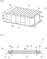
- FIG 3 On the figure 3 is shown a partial perspective view of an acoustic treatment panel 10 according to one embodiment of the invention.
- the acoustic treatment panel 10 comprises a core 12, a reflective layer or wall 14 and an inlet layer or wall 16 intended to be in contact with a fluid flow F, F P or F S .
- the core 12 has a honeycomb structure. More specifically, the core 12 comprises a plurality of acoustic cells 18, or alveoli, delimited by walls 180 and arranged according to a known honeycomb structure.
- Each cell 18 opens onto a first face 121 of the core 12 and onto a second face 122 of the core 12 located opposite the first face 121.
- the first face 121 of the core 12 is intended to be oriented towards the primary air flow vein 7 or secondary air flow vein 8 depending on the location of the acoustic treatment panel 10.
- the second face 122 of the core 12 is intended to be oriented opposite the air flow vein.
- the core 12 may be made of metal, or of a composite material, such as a composite material formed of carbon fibers embedded in a hardened resin matrix.
- the reflective layer 14 is adapted to reflect acoustic waves having a frequency belonging to the predetermined frequency range.
- the reflective layer 14 extends opposite the second face 122 of the core 12, being in contact with the second face 122. More precisely, the reflective layer 14 is integral with the second face 122 of the core 12, for example glued to the second face 122 of the core 12.
- the input layer 16 extends opposite the first face 121 of the core 12, being in contact with the first face 121. More precisely, the input layer 16 is integral with the first face 121 of the core 12, for example glued to the first face 121 of the core 12.
- FIG 6 schematically illustrated is a sectional view of a portion of the nacelle 2 of the propulsion unit 1 of the figure 2 according to one embodiment of the invention.
- the fixing edge 30 which extends in the extension of the entry layer 16 can be formed by the portion of reinforcing wall 22 extending outside the panel 10 in the extension of the second skin 16.
- the second skin 16 of the second acoustic treatment panel 10 is not integral with the radially internal wall 53 of the nacelle 2.
- the height of the two panels 10 and 100 may be different.
Landscapes
- Engineering & Computer Science (AREA)
- Chemical & Material Sciences (AREA)
- Combustion & Propulsion (AREA)
- Mechanical Engineering (AREA)
- General Engineering & Computer Science (AREA)
- Physics & Mathematics (AREA)
- Acoustics & Sound (AREA)
- Multimedia (AREA)
- Aviation & Aerospace Engineering (AREA)
- Soundproofing, Sound Blocking, And Sound Damping (AREA)
- Laminated Bodies (AREA)
Claims (12)
- Paneel (10) zur akustischen Behandlung, das dazu bestimmt ist, an zumindest einer Wand einer Triebwerksanordnung (1) eines Luftfahrzeugs, die mit einer Fluidströmung in Kontakt steht, angeordnet zu werden, wobei das Paneel (10) eine schallreflektierende erste Haut (14), eine schalldurchlässige zweite Haut (16), die dazu bestimmt ist, mit einer Fluidströmung (F, FP, FS) in Kontakt zu stehen, eine wabenförmige Struktur (12), die sich zwischen der ersten Haut (14) und der zweiten Haut (16) erstreckt und eine Vielzahl von Hohlräumen (18) beinhaltet, und zumindest eine schalldurchlässige Verstärkungswand (22) umfasst, die mehrere Hohlräume (18) der wabenförmigen Struktur durchquert und sich von der zweiten Haut (16) bis zu der ersten Haut (14) erstreckt, wobei sie einen nicht orthogonalen Winkel mit der ersten und der zweiten Haut (14 und 16) bildet,
dadurch gekennzeichnet, dass die zumindest eine Verstärkungswand (22) in einem Stück mit der schallreflektierenden ersten Haut (14) ausgebildet ist. - Paneel (10) zur akustischen Behandlung nach Anspruch 1, wobei die zumindest eine schalldurchlässige Verstärkungswand (22) einen Perforationsgrad von mehr als oder gleich 18 % aufweist.
- Paneel (10) zur akustischen Behandlung nach einem der Ansprüche 1 oder 2, wobei die wabenförmige Struktur (12) sich in einer Ebene parallel zu der zweiten Haut (16) innerhalb eines äußeren Umfangs erstreckt, und die zumindest eine Verstärkungswand (22) sich innerhalb der wabenförmigen Struktur (12) von der zweiten Haut (16) bis zu der ersten Haut (14) über einen Randabschnitt (24, 26) der wabenförmigen Struktur (12) erstreckt, der sich in der Ebene parallel zu der zweiten Haut (16) von dem äußeren Umfang zu dem Inneren der wabenförmigen Struktur (12) hin erstreckt.
- Paneel (10) nach einem der Ansprüche 1 bis 3, wobei die Verstärkungswand (22) einen Anbringungsabschnitt umfasst, der sich von der Außenseite des Paneels (10) in der Verlängerung der zweiten Haut (16) erstreckt, wobei der Anbringungsabschnitt dazu bestimmt ist, mit einer Wand der Triebwerksanordnung (1) gekoppelt zu werden.
- Paneel (10) nach einem der Ansprüche 1 bis 4, wobei die Verstärkungswand (22) einen Befestigungsabschnitt umfasst, der sich von der Außenseite des Paneels (10) in der Verlängerung der ersten Haut (14) erstreckt, wobei der Befestigungsabschnitt dazu bestimmt ist, mit einer Wand der Triebwerksanordnung (1) gekoppelt zu werden.
- Paneel (10) nach einem der Ansprüche 1 bis 4, umfassend zumindest einen Abschnitt des Paneels (10), der sich einer Richtung orthogonal zu der ersten Haut (14) folgend zwischen einer Verstärkungswand (22) und einem Abschnitt (142) der ersten Haut (14) erstreckt, wobei der zumindest eine Paneelabschnitt während der Herstellung des Paneels an den übrigen Teil des Paneels angestückt und durch gemeinsames Aushärten daran befestigt wird.
- Triebwerksanordnung (1), die dazu bestimmt ist, an einem Luftfahrzeug montiert zu werden, wobei die Triebwerksanordnung (1) zumindest ein Paneel zur akustischen Behandlung (10) nach einem der Ansprüche 1 bis 6 umfasst.
- Triebwerksanordnung (1) nach Anspruch 7, umfassend zumindest einen Lufteinlass (5), der mit einer vorderen Lippe (51), einer Außenwand (52) und einer Innenwand (53) ausgestattet ist und mit einem der Paneele zur akustischen Behandlung (10) verbunden ist, die zumindest einen Teil der Innenwand (53) bilden.
- Triebwerksanordnung (1) nach Anspruch 8, wobei die Verstärkungswand (22) des Paneels zur akustischen Behandlung (10) sich außerhalb des Paneels (10) fortsetzt und mit der vorderen Lippe (51) des Lufteinlasses (5) verbunden ist.
- Luftfahrzeug, umfassend zumindest eine Triebwerksanordnung (1) nach einem der Ansprüche 6 bis 9.
- Verfahren zur Herstellung eines Paneels (10) zur akustischen Behandlung, das dazu bestimmt ist, an zumindest einer Wand einer Triebwerksanordnung (1) eines Luftfahrzeugs, die mit einer Fluidströmung in Kontakt steht, angeordnet zu werden, wobei das Verfahren zur Herstellung des Paneels (10) einen Schritt des Stapelns einer schallreflektierenden ersten Haut (14), einer wabenförmigen Struktur (12) und einer schalldurchlässigen zweiten Haut (16) umfasst, die dazu bestimmt ist, mit einer Fluidströmung (F, FP, FS) in Kontakt zu stehen, wobei die wabenförmige Struktur (12) sich zwischen der ersten Haut (14) und der zweiten Haut (16) erstreckt und eine Vielzahl von Hohlräumen (18) beinhaltet, sowie den Schritt des Einlegens zumindest einer schalldurchlässigen Verstärkungswand (22), die mehrere Hohlräume (18) der wabenförmigen Struktur durchquert und sich von der zweiten Haut (16) bis zu der ersten Haut (14) erstreckt, wobei sie einen nicht orthogonalen Winkel mit der ersten und der zweiten Haut (14 und 16) bildet,
dadurch gekennzeichnet, dass die zumindest eine Verstärkungswand (22) in einem Stück mit der ersten schallreflektierenden Haut (14) ausgebildet ist. - Verfahren nach Anspruch 11, umfassend einen Schritt der Verwirklichung zumindest eines Paneelabschnitts, der dazu bestimmt ist, sich einer Richtung orthogonal zu der ersten Haut (14) folgend zwischen einer Verstärkungswand (22) und einem Abschnitt (142) der ersten Haut (14) zu erstrecken, und einen Schritt der Verbindung des zumindest einen Paneelabschnitts mit dem übrigen Teil des Paneels durch gemeinsames Aushärten.
Applications Claiming Priority (2)
| Application Number | Priority Date | Filing Date | Title |
|---|---|---|---|
| FR2106342A FR3124016B1 (fr) | 2021-06-15 | 2021-06-15 | Panneau de traitement acoustique renforcé pour un ensemble propulsif d’aéronef |
| PCT/FR2022/051110 WO2022263751A1 (fr) | 2021-06-15 | 2022-06-10 | Panneau de traitement acoustique renforcé pour un ensemble propulsif d'aeronef |
Publications (2)
| Publication Number | Publication Date |
|---|---|
| EP4355988A1 EP4355988A1 (de) | 2024-04-24 |
| EP4355988B1 true EP4355988B1 (de) | 2025-03-05 |
Family
ID=78049289
Family Applications (1)
| Application Number | Title | Priority Date | Filing Date |
|---|---|---|---|
| EP22735211.9A Active EP4355988B1 (de) | 2021-06-15 | 2022-06-10 | Verstärkte schallbehandlungsplatte für eine flugzeugantriebseinheit |
Country Status (5)
| Country | Link |
|---|---|
| US (1) | US12077309B2 (de) |
| EP (1) | EP4355988B1 (de) |
| CN (1) | CN117730197A (de) |
| FR (1) | FR3124016B1 (de) |
| WO (1) | WO2022263751A1 (de) |
Families Citing this family (2)
| Publication number | Priority date | Publication date | Assignee | Title |
|---|---|---|---|---|
| FR3126340B1 (fr) * | 2021-08-30 | 2023-11-03 | Safran Nacelles | Panneau acoustique à cavités obliques |
| FR3134220A1 (fr) * | 2022-04-01 | 2023-10-06 | Airbus Operations (S.A.S.) | Panneau acoustique comprenant au moins deux structures alvéolaires imbriquées l’une dans l’autre, aéronef comportant au moins un tel panneau acoustique |
Family Cites Families (9)
| Publication number | Priority date | Publication date | Assignee | Title |
|---|---|---|---|---|
| US4265955A (en) * | 1978-05-01 | 1981-05-05 | The Boeing Company | Honeycomb core with internal septum and method of making same |
| US4910065A (en) * | 1987-10-15 | 1990-03-20 | The Boeing Company | Reinforced honeycomb core sandwich panels and method for making same |
| DE102007060668A1 (de) * | 2007-12-17 | 2009-06-18 | Airbus Deutschland Gmbh | Sandwichpaneel zur Schallabsorption |
| US9514734B1 (en) * | 2011-06-30 | 2016-12-06 | The United States Of America As Represented By The Administrator Of National Aeronautics And Space Administration | Acoustic liners for turbine engines |
| US8863893B2 (en) * | 2011-11-17 | 2014-10-21 | Spirit Aerosystems, Inc. | Engine inlet varying impedance acoustic liner section |
| FR2985287B1 (fr) * | 2012-01-04 | 2018-02-23 | Safran Nacelles | Structure acoustique alveolaire pour turboreacteur et turboreacteur incorporant au moins une telle structure |
| US9604438B2 (en) * | 2014-04-30 | 2017-03-28 | The Boeing Company | Methods and apparatus for noise attenuation in an engine nacelle |
| US10436118B2 (en) * | 2017-06-19 | 2019-10-08 | Rohr, Inc. | Acoustic panel with folding chamber |
| US11257474B2 (en) * | 2017-10-10 | 2022-02-22 | Auralex Acoustics | Acoustic system and method |
-
2021
- 2021-06-15 FR FR2106342A patent/FR3124016B1/fr active Active
-
2022
- 2022-06-10 WO PCT/FR2022/051110 patent/WO2022263751A1/fr not_active Ceased
- 2022-06-10 EP EP22735211.9A patent/EP4355988B1/de active Active
- 2022-06-10 US US18/571,073 patent/US12077309B2/en active Active
- 2022-06-10 CN CN202280049500.7A patent/CN117730197A/zh active Pending
Also Published As
| Publication number | Publication date |
|---|---|
| US12077309B2 (en) | 2024-09-03 |
| EP4355988A1 (de) | 2024-04-24 |
| FR3124016B1 (fr) | 2024-01-05 |
| US20240217667A1 (en) | 2024-07-04 |
| WO2022263751A1 (fr) | 2022-12-22 |
| CN117730197A (zh) | 2024-03-19 |
| FR3124016A1 (fr) | 2022-12-16 |
Similar Documents
| Publication | Publication Date | Title |
|---|---|---|
| EP3963192B1 (de) | Integration eines lüfterflatterdämpfers in ein motorgehäuse | |
| EP3850616B1 (de) | Schalldämmplatte für ein turbostrahltriebwerk | |
| EP1213703B1 (de) | Akustische Platte mit Sandwichaufbau | |
| EP2516271B1 (de) | Triebwerksgondel mit einem element zur verbindung einer umkantung mit einer schalldämmungsplatte | |
| EP4355988B1 (de) | Verstärkte schallbehandlungsplatte für eine flugzeugantriebseinheit | |
| EP2763892B1 (de) | Verfahren zur herstellung einer schalldämmenden tafel | |
| WO2017021628A1 (fr) | Structure d'atténuation acoustique à multiples degrés d'atténuation pour ensemble propulsif d'aéronef | |
| CA2770257A1 (fr) | Ensemble structurant pour une tuyere d'ejection | |
| EP2334557A1 (de) | Vorrichtung zur verbindung eines lufteinlasses mit einer flugzeuggondelbetätigungsanordnung | |
| WO2013024218A1 (fr) | Cône d'éjection pour turboréacteur d'aéronef | |
| EP3534360A1 (de) | Schalldämmende beschichtung, die eine wabenstruktur mit gekrümmten zellen umfasst, die auf der einen und der anderen seite aus derselben innenwand gebildet werden | |
| EP4264594A1 (de) | Schallbehandlungsplatte mit reduzierter volumenleistung für ein turbostrahltriebwerk | |
| EP3620631B1 (de) | Lufteinlassstruktur für eine luftfahrzeuggondel | |
| EP2791006B1 (de) | Lufteinlassstruktur für eine turbostrahl-motorengondel | |
| EP3620297B1 (de) | Schalldämmende platte mit einem wabenkern und einem enteisungssystem | |
| EP3552951B1 (de) | Schalldämmplatte für luftfahrzeug, die kombinierte schallabsorptionseigenschaften aufweist | |
| EP3792469B1 (de) | Lufteinlass, gondel, antriebseinheit und luftfahrzeug mit gerillter einlasslippe | |
| FR3120352A1 (fr) | Entree d’air de nacelle munie d’un système de protection contre la glace mixte | |
| WO2009115700A1 (fr) | Panneau acoustique d'une nacelle d'un aerone | |
| EP4066235B1 (de) | Resonanz-patch und akustische behandlungszelle mit einem solchen patch | |
| FR3141551A1 (fr) | Procédé de formation d’une structure d’atténuation acoustique dotée de cellules en S | |
| EP4654182A1 (de) | Schallabsorbierende struktur mit mindestens einem in mindestens einer zelle positionierten trennwandsystem zur bildung zweier resonatortypen, verfahren zur herstellung einer solchen struktur |
Legal Events
| Date | Code | Title | Description |
|---|---|---|---|
| STAA | Information on the status of an ep patent application or granted ep patent |
Free format text: STATUS: UNKNOWN |
|
| STAA | Information on the status of an ep patent application or granted ep patent |
Free format text: STATUS: THE INTERNATIONAL PUBLICATION HAS BEEN MADE |
|
| PUAI | Public reference made under article 153(3) epc to a published international application that has entered the european phase |
Free format text: ORIGINAL CODE: 0009012 |
|
| STAA | Information on the status of an ep patent application or granted ep patent |
Free format text: STATUS: REQUEST FOR EXAMINATION WAS MADE |
|
| 17P | Request for examination filed |
Effective date: 20231222 |
|
| AK | Designated contracting states |
Kind code of ref document: A1 Designated state(s): AL AT BE BG CH CY CZ DE DK EE ES FI FR GB GR HR HU IE IS IT LI LT LU LV MC MK MT NL NO PL PT RO RS SE SI SK SM TR |
|
| DAV | Request for validation of the european patent (deleted) | ||
| DAX | Request for extension of the european patent (deleted) | ||
| GRAP | Despatch of communication of intention to grant a patent |
Free format text: ORIGINAL CODE: EPIDOSNIGR1 |
|
| STAA | Information on the status of an ep patent application or granted ep patent |
Free format text: STATUS: GRANT OF PATENT IS INTENDED |
|
| INTG | Intention to grant announced |
Effective date: 20240930 |
|
| GRAS | Grant fee paid |
Free format text: ORIGINAL CODE: EPIDOSNIGR3 |
|
| GRAA | (expected) grant |
Free format text: ORIGINAL CODE: 0009210 |
|
| STAA | Information on the status of an ep patent application or granted ep patent |
Free format text: STATUS: THE PATENT HAS BEEN GRANTED |
|
| AK | Designated contracting states |
Kind code of ref document: B1 Designated state(s): AL AT BE BG CH CY CZ DE DK EE ES FI FR GB GR HR HU IE IS IT LI LT LU LV MC MK MT NL NO PL PT RO RS SE SI SK SM TR |
|
| REG | Reference to a national code |
Ref country code: GB Ref legal event code: FG4D Free format text: NOT ENGLISH |
|
| REG | Reference to a national code |
Ref country code: CH Ref legal event code: EP |
|
| REG | Reference to a national code |
Ref country code: DE Ref legal event code: R096 Ref document number: 602022011495 Country of ref document: DE |
|
| REG | Reference to a national code |
Ref country code: IE Ref legal event code: FG4D Free format text: LANGUAGE OF EP DOCUMENT: FRENCH |
|
| PG25 | Lapsed in a contracting state [announced via postgrant information from national office to epo] |
Ref country code: RS Free format text: LAPSE BECAUSE OF FAILURE TO SUBMIT A TRANSLATION OF THE DESCRIPTION OR TO PAY THE FEE WITHIN THE PRESCRIBED TIME-LIMIT Effective date: 20250605 |
|
| PG25 | Lapsed in a contracting state [announced via postgrant information from national office to epo] |
Ref country code: FI Free format text: LAPSE BECAUSE OF FAILURE TO SUBMIT A TRANSLATION OF THE DESCRIPTION OR TO PAY THE FEE WITHIN THE PRESCRIBED TIME-LIMIT Effective date: 20250305 |
|
| PGFP | Annual fee paid to national office [announced via postgrant information from national office to epo] |
Ref country code: DE Payment date: 20250618 Year of fee payment: 4 |
|
| REG | Reference to a national code |
Ref country code: NL Ref legal event code: MP Effective date: 20250305 |
|
| PG25 | Lapsed in a contracting state [announced via postgrant information from national office to epo] |
Ref country code: ES Free format text: LAPSE BECAUSE OF FAILURE TO SUBMIT A TRANSLATION OF THE DESCRIPTION OR TO PAY THE FEE WITHIN THE PRESCRIBED TIME-LIMIT Effective date: 20250305 |
|
| REG | Reference to a national code |
Ref country code: LT Ref legal event code: MG9D |
|
| PG25 | Lapsed in a contracting state [announced via postgrant information from national office to epo] |
Ref country code: NO Free format text: LAPSE BECAUSE OF FAILURE TO SUBMIT A TRANSLATION OF THE DESCRIPTION OR TO PAY THE FEE WITHIN THE PRESCRIBED TIME-LIMIT Effective date: 20250605 |
|
| PG25 | Lapsed in a contracting state [announced via postgrant information from national office to epo] |
Ref country code: HR Free format text: LAPSE BECAUSE OF FAILURE TO SUBMIT A TRANSLATION OF THE DESCRIPTION OR TO PAY THE FEE WITHIN THE PRESCRIBED TIME-LIMIT Effective date: 20250305 |
|
| PG25 | Lapsed in a contracting state [announced via postgrant information from national office to epo] |
Ref country code: LV Free format text: LAPSE BECAUSE OF FAILURE TO SUBMIT A TRANSLATION OF THE DESCRIPTION OR TO PAY THE FEE WITHIN THE PRESCRIBED TIME-LIMIT Effective date: 20250305 |
|
| PGFP | Annual fee paid to national office [announced via postgrant information from national office to epo] |
Ref country code: FR Payment date: 20250623 Year of fee payment: 4 |
|
| PG25 | Lapsed in a contracting state [announced via postgrant information from national office to epo] |
Ref country code: BG Free format text: LAPSE BECAUSE OF FAILURE TO SUBMIT A TRANSLATION OF THE DESCRIPTION OR TO PAY THE FEE WITHIN THE PRESCRIBED TIME-LIMIT Effective date: 20250305 Ref country code: GR Free format text: LAPSE BECAUSE OF FAILURE TO SUBMIT A TRANSLATION OF THE DESCRIPTION OR TO PAY THE FEE WITHIN THE PRESCRIBED TIME-LIMIT Effective date: 20250606 |
|
| PG25 | Lapsed in a contracting state [announced via postgrant information from national office to epo] |
Ref country code: NL Free format text: LAPSE BECAUSE OF FAILURE TO SUBMIT A TRANSLATION OF THE DESCRIPTION OR TO PAY THE FEE WITHIN THE PRESCRIBED TIME-LIMIT Effective date: 20250305 |
|
| PG25 | Lapsed in a contracting state [announced via postgrant information from national office to epo] |
Ref country code: SE Free format text: LAPSE BECAUSE OF FAILURE TO SUBMIT A TRANSLATION OF THE DESCRIPTION OR TO PAY THE FEE WITHIN THE PRESCRIBED TIME-LIMIT Effective date: 20250305 |
|
| PG25 | Lapsed in a contracting state [announced via postgrant information from national office to epo] |
Ref country code: SM Free format text: LAPSE BECAUSE OF FAILURE TO SUBMIT A TRANSLATION OF THE DESCRIPTION OR TO PAY THE FEE WITHIN THE PRESCRIBED TIME-LIMIT Effective date: 20250305 |
|
| PG25 | Lapsed in a contracting state [announced via postgrant information from national office to epo] |
Ref country code: PT Free format text: LAPSE BECAUSE OF FAILURE TO SUBMIT A TRANSLATION OF THE DESCRIPTION OR TO PAY THE FEE WITHIN THE PRESCRIBED TIME-LIMIT Effective date: 20250707 |
|
| PG25 | Lapsed in a contracting state [announced via postgrant information from national office to epo] |
Ref country code: PL Free format text: LAPSE BECAUSE OF FAILURE TO SUBMIT A TRANSLATION OF THE DESCRIPTION OR TO PAY THE FEE WITHIN THE PRESCRIBED TIME-LIMIT Effective date: 20250305 Ref country code: IT Free format text: LAPSE BECAUSE OF FAILURE TO SUBMIT A TRANSLATION OF THE DESCRIPTION OR TO PAY THE FEE WITHIN THE PRESCRIBED TIME-LIMIT Effective date: 20250305 |
|
| PG25 | Lapsed in a contracting state [announced via postgrant information from national office to epo] |
Ref country code: AT Free format text: LAPSE BECAUSE OF FAILURE TO SUBMIT A TRANSLATION OF THE DESCRIPTION OR TO PAY THE FEE WITHIN THE PRESCRIBED TIME-LIMIT Effective date: 20250305 |
|
| PG25 | Lapsed in a contracting state [announced via postgrant information from national office to epo] |
Ref country code: EE Free format text: LAPSE BECAUSE OF FAILURE TO SUBMIT A TRANSLATION OF THE DESCRIPTION OR TO PAY THE FEE WITHIN THE PRESCRIBED TIME-LIMIT Effective date: 20250305 Ref country code: CZ Free format text: LAPSE BECAUSE OF FAILURE TO SUBMIT A TRANSLATION OF THE DESCRIPTION OR TO PAY THE FEE WITHIN THE PRESCRIBED TIME-LIMIT Effective date: 20250305 |
|
| PG25 | Lapsed in a contracting state [announced via postgrant information from national office to epo] |
Ref country code: RO Free format text: LAPSE BECAUSE OF FAILURE TO SUBMIT A TRANSLATION OF THE DESCRIPTION OR TO PAY THE FEE WITHIN THE PRESCRIBED TIME-LIMIT Effective date: 20250305 |
|
| PG25 | Lapsed in a contracting state [announced via postgrant information from national office to epo] |
Ref country code: SK Free format text: LAPSE BECAUSE OF FAILURE TO SUBMIT A TRANSLATION OF THE DESCRIPTION OR TO PAY THE FEE WITHIN THE PRESCRIBED TIME-LIMIT Effective date: 20250305 |
|
| PG25 | Lapsed in a contracting state [announced via postgrant information from national office to epo] |
Ref country code: IS Free format text: LAPSE BECAUSE OF FAILURE TO SUBMIT A TRANSLATION OF THE DESCRIPTION OR TO PAY THE FEE WITHIN THE PRESCRIBED TIME-LIMIT Effective date: 20250705 |
|
| REG | Reference to a national code |
Ref country code: DE Ref legal event code: R097 Ref document number: 602022011495 Country of ref document: DE |
|
| PLBE | No opposition filed within time limit |
Free format text: ORIGINAL CODE: 0009261 |
|
| STAA | Information on the status of an ep patent application or granted ep patent |
Free format text: STATUS: NO OPPOSITION FILED WITHIN TIME LIMIT |
|
| PG25 | Lapsed in a contracting state [announced via postgrant information from national office to epo] |
Ref country code: DK Free format text: LAPSE BECAUSE OF FAILURE TO SUBMIT A TRANSLATION OF THE DESCRIPTION OR TO PAY THE FEE WITHIN THE PRESCRIBED TIME-LIMIT Effective date: 20250305 |
|
| REG | Reference to a national code |
Ref country code: CH Ref legal event code: L10 Free format text: ST27 STATUS EVENT CODE: U-0-0-L10-L00 (AS PROVIDED BY THE NATIONAL OFFICE) Effective date: 20260114 |
|
| REG | Reference to a national code |
Ref country code: CH Ref legal event code: H13 Free format text: ST27 STATUS EVENT CODE: U-0-0-H10-H13 (AS PROVIDED BY THE NATIONAL OFFICE) Effective date: 20260127 |
|
| PG25 | Lapsed in a contracting state [announced via postgrant information from national office to epo] |
Ref country code: MC Free format text: LAPSE BECAUSE OF FAILURE TO SUBMIT A TRANSLATION OF THE DESCRIPTION OR TO PAY THE FEE WITHIN THE PRESCRIBED TIME-LIMIT Effective date: 20250305 |
|
| 26N | No opposition filed |
Effective date: 20251208 |
|
| PG25 | Lapsed in a contracting state [announced via postgrant information from national office to epo] |
Ref country code: LU Free format text: LAPSE BECAUSE OF NON-PAYMENT OF DUE FEES Effective date: 20250610 |
|
| REG | Reference to a national code |
Ref country code: BE Ref legal event code: MM Effective date: 20250630 |
|
| PG25 | Lapsed in a contracting state [announced via postgrant information from national office to epo] |
Ref country code: IE Free format text: LAPSE BECAUSE OF NON-PAYMENT OF DUE FEES Effective date: 20250610 |
|
| PG25 | Lapsed in a contracting state [announced via postgrant information from national office to epo] |
Ref country code: BE Free format text: LAPSE BECAUSE OF NON-PAYMENT OF DUE FEES Effective date: 20250630 |