EP3535143B1 - Drehkupplungsanordnung für ein reifenfüllsystem - Google Patents
Drehkupplungsanordnung für ein reifenfüllsystem Download PDFInfo
- Publication number
- EP3535143B1 EP3535143B1 EP17794696.9A EP17794696A EP3535143B1 EP 3535143 B1 EP3535143 B1 EP 3535143B1 EP 17794696 A EP17794696 A EP 17794696A EP 3535143 B1 EP3535143 B1 EP 3535143B1
- Authority
- EP
- European Patent Office
- Prior art keywords
- annular
- rotatable
- rotatable portion
- rotation
- axis
- Prior art date
- Legal status (The legal status is an assumption and is not a legal conclusion. Google has not performed a legal analysis and makes no representation as to the accuracy of the status listed.)
- Not-in-force
Links
Images

Classifications
-
- B—PERFORMING OPERATIONS; TRANSPORTING
- B60—VEHICLES IN GENERAL
- B60C—VEHICLE TYRES; TYRE INFLATION; TYRE CHANGING; CONNECTING VALVES TO INFLATABLE ELASTIC BODIES IN GENERAL; DEVICES OR ARRANGEMENTS RELATED TO TYRES
- B60C23/00—Devices for measuring, signalling, controlling, or distributing tyre pressure or temperature, specially adapted for mounting on vehicles; Arrangement of tyre inflating devices on vehicles, e.g. of pumps or of tanks; Tyre cooling arrangements
- B60C23/001—Devices for manually or automatically controlling or distributing tyre pressure whilst the vehicle is moving
- B60C23/003—Devices for manually or automatically controlling or distributing tyre pressure whilst the vehicle is moving comprising rotational joints between vehicle-mounted pressure sources and the tyres
- B60C23/00363—Details of sealings
-
- B—PERFORMING OPERATIONS; TRANSPORTING
- B60—VEHICLES IN GENERAL
- B60C—VEHICLE TYRES; TYRE INFLATION; TYRE CHANGING; CONNECTING VALVES TO INFLATABLE ELASTIC BODIES IN GENERAL; DEVICES OR ARRANGEMENTS RELATED TO TYRES
- B60C23/00—Devices for measuring, signalling, controlling, or distributing tyre pressure or temperature, specially adapted for mounting on vehicles; Arrangement of tyre inflating devices on vehicles, e.g. of pumps or of tanks; Tyre cooling arrangements
- B60C23/001—Devices for manually or automatically controlling or distributing tyre pressure whilst the vehicle is moving
- B60C23/003—Devices for manually or automatically controlling or distributing tyre pressure whilst the vehicle is moving comprising rotational joints between vehicle-mounted pressure sources and the tyres
- B60C23/00309—Devices for manually or automatically controlling or distributing tyre pressure whilst the vehicle is moving comprising rotational joints between vehicle-mounted pressure sources and the tyres characterised by the location of the components, e.g. valves, sealings, conduits or sensors
- B60C23/00318—Devices for manually or automatically controlling or distributing tyre pressure whilst the vehicle is moving comprising rotational joints between vehicle-mounted pressure sources and the tyres characterised by the location of the components, e.g. valves, sealings, conduits or sensors on the wheels or the hubs
-
- B—PERFORMING OPERATIONS; TRANSPORTING
- B60—VEHICLES IN GENERAL
- B60C—VEHICLE TYRES; TYRE INFLATION; TYRE CHANGING; CONNECTING VALVES TO INFLATABLE ELASTIC BODIES IN GENERAL; DEVICES OR ARRANGEMENTS RELATED TO TYRES
- B60C23/00—Devices for measuring, signalling, controlling, or distributing tyre pressure or temperature, specially adapted for mounting on vehicles; Arrangement of tyre inflating devices on vehicles, e.g. of pumps or of tanks; Tyre cooling arrangements
- B60C23/001—Devices for manually or automatically controlling or distributing tyre pressure whilst the vehicle is moving
- B60C23/003—Devices for manually or automatically controlling or distributing tyre pressure whilst the vehicle is moving comprising rotational joints between vehicle-mounted pressure sources and the tyres
- B60C23/00345—Details of the rotational joints
Definitions
- the invention relates primarily to a rotary joint assembly for a tire inflation system.
- Tire inflation systems are used in different types of vehicles such as trucks, tractors or earth-moving machines.
- the main objective of a tire inflation system is to adapt the tire pressure to different operating conditions.
- these conditions include at least one of the ground the vehicle is travelling on, a vehicle speed and a vehicle load.
- the contact patch of a tire is influenced by the tire pressure.
- As the tire pressure is decreased the contact patch increases.
- As the tire pressure is increased the contact patch decreases. For this reason, it is desirable to optimize the tire pressure depending on ground conditions. For example, a lower tire pressure may be adopted when the vehicle is traveling on soft surfaces such as gravel.
- a higher tire pressure may be chosen when the vehicle is traveling on hard surfaces such as tarmac or concrete.
- a tire inflation system may improve the longevity of the tire, reduce soil compaction, lower fuel consumption, and reduce overall operating costs.
- tire inflation systems known from the prior art comprise rotary joints, also termed rotary joints or rotary seal arrangements. These may be disposed between a stationary portion of the vehicle such as an axle housing, a steering knuckle or a spindle, and a rotatable or rotating portion such as wheel hub on which the wheel and the tire may be mounted, for example.
- a stationary portion of the vehicle such as an axle housing, a steering knuckle or a spindle, and a rotatable or rotating portion such as wheel hub on which the wheel and the tire may be mounted, for example.
- the functioning of a rotary joint is critical for the tire inflation system because the rotary joint should preferably be configured to transmit fluid used for inflating the tire from a pneumatic line to a wheel valve while the vehicle wheel is rotating.
- rotary seal arrangements include sealing means mounted on the stationary portion and/or on the rotatable portion. Usually, the sealing means are configured to be in sliding engagement when the wheel is rotating. In this way, the sealing means form an annul
- WO 2013/156430 A1 describes a spindle assembly for a tire inflation system in which some of the fluid lines are integrated in the vehicle axle.
- this solution may require the design of the rotatable portion, for example a wheel hub, to be adapted to the design of the spindle, for example. In some cases this may imply that deep bores have to be drilled in the axle which may possibly complicate the manufacturing process.
- the spatial extension of the assembly in particular its axial extension, must accommodate all sealings and fluid lines.
- the length of the axle including the tire inflation system is required to be below a given maximum length.
- GB2477816A relates to a central tire inflation system for a vehicle having a plurality of wheel hub assemblies.
- the system includes means for the controlled supply of compressed air to a chamber within each of the wheel hub assemblies.
- Each chamber is bounded by seals that act between a stub axle tube and a hub extension.
- DE102014221813 B3 relates to a device for adjusting the air pressure of a pneumatic tire arranged on a vehicle axle via a rim.
- the prior art does not disclose a bearing supporting an inner face of a rotatable portion, wherein the inner face of the rotatable portion faces toward the axis of rotation.
- the presently proposed rotary joint assembly for a tire inflation system for a vehicle comprises:
- the support portion, the first annular sealing face, and the second annular sealing face may be arranged concentrically with respect to the axis of rotation.
- the first annular sealing face and the second annular sealing face may be oriented in parallel to the axis of rotation.
- a maximum radius of the support portion, the first annular sealing face, and the second annular sealing face may be disposed, respectively, at a first, at a second and at a third radial distance from the axis of rotation.
- the second radial distance may be larger than the first radial distance
- the third radial distance may be larger than the second radial distance.
- the term fluid refers to a gaseous medium such as air which may be used for inflating a pneumatic tire of an automotive vehicle.
- the support portion and the first sealing face of the stationary portion may be disposed at different radial distances from the axis of rotation typically facilitates a particularly compact arrangement of the rotary joint assembly, in particular along an axial direction oriented in parallel to the axis of rotation of the rotatable portion.
- the annular seal chamber and one or more bearings that may be disposed between the support portion and the rotatable portion for supporting the rotatable portion may be at least partially stacked along the radial direction.
- the stationary portion may include an axle housing, a spindle or a knuckle, for example a steering knuckle.
- the rotatable portion may be configured to support a wheel and a pneumatic tire, that is a wheel and a pneumatic tire may be mounted on the rotatable portion.
- the rotatable portion may include a wheel hub or similar rotatable component.
- the stationary portion and/or the rotatable portion may be made of metal or may comprise metal.
- the first fluid passage may be configured to be in fluid communication with a pressure source such as a compressor and/or with a vent.
- the compressor and/or the vent may be mounted on the vehicle.
- the second fluid passage may be configured to be in fluid communication with a pneumatic tire mounted on the rotatable portion.
- the second fluid passage is in fluid communication with the pneumatic tire by way of a flow control valve.
- the pressure source may pressurize the tire via the first fluid passage, the annular seal chamber, and the second fluid passage.
- the tire may be deflated via the second fluid passage, the annular seal chamber, the first fluid passage and the vent, for example.
- the tire may be inflated and deflated through the rotary joint assembly while the vehicle on which the rotary joint assembly and the tire are mounted is moving, i. e. while the rotatable portion is rotating relative to the stationary portion.
- the annular seal chamber is configured to guide fluid that is transported from the first fluid passage to the second fluid passage or vice versa through the annular seal chamber and to prevent the leakage of fluid out of the annular seal chamber.
- the annular seal chamber may be formed by sealing lips, for example by a pair of sealing lips.
- the sealing lips forming the annular seal chamber may be axially spaced from one another.
- the sealing lips delimit the annular seal chamber in the axial direction
- the first and the second annular sealing face delimit the annular seal chamber in the radial direction.
- the sealing lips may comprise a rubber material such as PTFE.
- the sealing lips or some of the sealing lips forming the annular seal chamber may be mounted on the rotatable portion, in particular on the second sealing face of the rotatable portion. These sealing lips may then be in sliding sealing engagement with the stationary portion, in particular with the first sealing face of the stationary portion. However, it is understood that additionally or alternatively the sealing lips or some of the sealing lips may be mounted on the stationary portion, in particular on the first sealing face of the stationary portion. These sealing lips may then be in sliding sealing engagement with the rotatable portion, in particular with the second sealing face of the rotatable portion.
- first annular sealing face faces away from the axis of rotation
- second annular sealing face faces toward the axis of rotation
- the at least one bearing may comprise a pair of bearings, for example for rotatably mounting the rotatable portion on the support portion of the stationary portion.
- the inner face of the rotatable portion may be disposed at a fourth radial distance from the axis of rotation, wherein the second radial distance associated with the first sealing face of the stationary portion may be larger than the fourth radial distance associated with the inner face of the rotatable portion with is mounted on the at least one bearing.
- the stationary portion may further comprise a main portion and an annular portion. The main portion of the stationary portion may be integrally formed with the support portion of the stationary portion.
- the main portion of the stationary portion and the annular portion of the stationary portion may be configured as separate portions, wherein the annular portion of the stationary portion is fixedly coupled to the main portion of the stationary portion, and wherein the first annular sealing face is formed on the annular portion of the stationary portion.
- the annular portion of the stationary portion may be coupled to or mounted on the main portion of the stationary portion in any conventional manner. Providing the main portion of the stationary portion and the annular portion of the stationary portion as separate portions may facilitate the installation of the rotary joint assembly. However, it is understood that the annular portion of the stationary portion may likewise be integrally formed with the main portion of the stationary portion.
- the main portion of the stationary portion may define a first section of the first fluid passage, and the annular portion of the stationary portion may define a second section of the first fluid passage, wherein the first and the second section of the first fluid passage are in fluid communication with one another.
- the rotary joint assembly may then comprise sealing means disposed at an interface of the first and the second section of the first fluid passage to prevent fluid leakage at the interface between the first and the second section of the first fluid passage.
- the rotatable portion may comprise a main portion and a first axially extending annular protrusion, wherein the first axially extending annular protrusion of the rotatable portion protrudes from the main portion of the rotatable portion in parallel to the axis of rotation and toward the stationary portion.
- the second annular sealing face of the rotatable portion may be formed on the first axially extending annular protrusion of the rotatable portion.
- the main portion of the rotatable portion and the first axially extending annular protrusion of the rotatable portion may be configured as separate portions.
- the first axially extending annular protrusion may then be fixedly coupled to or mounted on the main portion of the rotatable portion.
- the annular portion of the rotatable portion may be coupled to or mounted on the main portion of the rotatable portion in any conventional manner.
- Providing the main portion of the rotatable portion and the first axially extending annular protrusion of the rotatable portion as separate portions may facilitate the installation of the rotary joint assembly.
- the first axially extending annular protrusion may likewise be integrally formed with the main portion of the rotatable portion.
- the stationary portion and the rotatable portion may be configured or formed to encompass an annular space formed between the stationary portion and the rotatable portion.
- the annular seal chamber may be disposed within this annular space.
- the above-described annular portion of the stationary portion may be received or at least partially received within the annular space. This design may add to the compactness of the rotary joint assembly.
- the rotary joint assembly may comprise a first annular seal assembly sealing the annular space and the annular seal chamber disposed within the annular space from the atmosphere.
- the first annular seal assembly may comprise one or more sealing rings, for example.
- the first annular seal assembly may be mounted on the stationary portion and/or on the rotatable portion, in particular on a side of the rotatable portion facing toward the axis of rotation. Specifically, the sealing rings of the first annular seal assembly may be mounted on the stationary portion and/or on the rotatable portion.
- the annular space may be formed between the first axially extending annular protrusion of the rotatable portion and the stationary portion.
- the first annular seal assembly may be disposed between the first axially extending annular protrusion of the rotatable portion and the stationary portion.
- the first annular seal assembly may be mounted on the first axially extending annular protrusion of the rotatable portion, in particular on a side of the first axially extending annular protrusion of the rotatable portion facing toward the axis of rotation.
- the sealing rings of the first annular seal assembly may be mounted on the first axially extending annular protrusion of the rotatable portion.
- the rotary joint assembly may further comprise a second annular seal assembly.
- the second annular seal assembly may be disposed between the stationary portion and the rotatable portion and may seal the annular space and the annular seal chamber disposed within the annular space from the at least one bearing disposed between the support portion of the stationary portion and the rotatable portion, in particular from lubricants used for lubricating the at least one bearing.
- the second annular seal assembly may comprise one or more sealing rings, for example.
- the second annular seal assembly may be mounted on the stationary portion and/or on the rotatable portion, in particular on a side of the rotatable portion facing toward the axis of rotation.
- sealing rings or some of the sealing rings of the second annular seal assembly may be mounted on the stationary portion and/or on the rotatable portion.
- the sealing rings or some of the sealing rings of the second annular seal assembly may be in sliding sealing contact with one another, with the stationary portion, and/or with the rotatable portion.
- the rotatable portion may further comprise a second axially extending annular protrusion, wherein the second axially extending annular protrusion of the rotatable portion protrudes from the main portion of the rotatable portion in parallel to the axis of rotation and toward the stationary portion.
- the above-described annular space may be formed between the first and the second axially extending annular protrusion of the rotatable portion and the stationary portion.
- the second annular seal assembly may be disposed between the second axially extending annular protrusion of the rotatable portion, in particular on an inner side of the second axially extending annular protrusion facing the axis of rotation, and the stationary portion.
- the first annular seal assembly and the second annular seal assembly may be disposed, respectively, at a fifth and at a sixth radial distance from the axis of rotation.
- the fifth radial distance may be larger than the sixth radial distance.
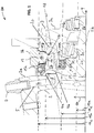
- FIG. 1 illustrates a first sectional view of a rotary joint assembly 100 for a tire inflation system of an automotive vehicle, for example of an off-highway vehicle such as a tractor or a material handling vehicle.
- the assembly 100 comprises a stationary portion 2, for example an axle housing or a steering knuckle.
- the stationary portion 2 comprises a main portion 2a, a support portion 2b, and an annular portion 2c.
- the main portion 2a and the support portion 2b of the stationary portion 2 are integrally formed.
- the annular portion 2c of the stationary portion 2 is formed a separate portion which is fixedly mounted on a first shoulder 4a and on a second shoulder 4b of the main portion 2b of the stationary portion 2.
- the annular portion 2c and the main portion 2a of the stationary portion 2 may be integrally formed.
- the stationary portion 2 defines a first fluid passage 5 for a gaseous medium such as air.
- the main portion 2a of the stationary portion 2 defines a first section 5a of the first fluid passage 5, and the separate annular portion 2b of the stationary portion 2 defines a second section 5b of the first fluid passage 5.
- the first section 5a of the first fluid passage 5 is in fluid communication with the second section 5b of the first fluid passage 5.
- Sealing means 6 disposed at an interface between the first section 5a and the second section 5b prevents the leakage of fluid at the interface.
- the first section 5a of the first fluid passage 5 ends in a fitting 7 that is screwed into a bore in the main portion 2a of the stationary portion 2. Via the fitting 7 the first fluid passage 5 may be in fluid communication with a source of pressurized fluid such as a compressor for pressurizing the first fluid passage 5, and/or with a vent for venting the first fluid passage 5.
- the rotary joint 100 further comprises a rotatable portion 3 such as a wheel hub.
- the rotatable portion 3 is rotatably mounted on the main portion 2b of the stationary portion 2 by means of a pair of pair of bearings 8a, 8b.
- the bearings 8a, 8b are configured as roller bearings and are mounted on the support portion 2b of the stationary portion 2.
- An axis of rotation 9 of the rotatable portion 3 defines an axial direction.
- a radial direction 10 is oriented perpendicular to the axial direction 9.
- An outer face 20 of the support portion 2b of the stationary portion 2 is disposed at a first radial distance 19a from the axis of rotation 9.
- the outer face 20 of the support portion 2b is facing away from the axis of rotation 9.
- the radius of the support portion 2b of the stationary portion 2 has a maximum value.
- the rotatable portion 3 comprises a main portion 3a, a first axially extending annular protrusion 3b, and a second axially extending annular protrusion 3c.
- the first bearing 8a supports a first inner face 11a of the main portion 3a of the rotatable portion 3
- the second bearing 8b supports a second inner face 11b of the main portion 3a of the rotatable portion 3.
- the inner faces 11a, 11b of the main portion 3a of the rotatable portion 3 face toward the axis of rotation 9.
- the first and the second axially extending annular protrusion 3b and 3c of the rotatable portion 3 protrude from the main portion 3a of the rotatable portion 3 in parallel to the axis of rotation 9 or essentially in parallel to the axis of rotation and toward the stationary portion 2.
- the main portion 3a and the second axially extending annular protrusion 3c of the rotatable portion 3 are integrally formed.
- the first axially extending annular protrusion 3b of the rotatable portion 3 is formed a separate portion which is fixedly mounted on a first shoulder 12 of the main portion 3a of the rotatable portion 3.
- the first axially extending annular protrusion 3b and the main portion 3a of the rotatable portion 3 may be integrally formed.
- the annular portion 2c of the stationary portion 2 has a first annular sealing face 14, and the first axially extending annular protrusion 3b of the rotatable portion 3 has a second annular sealing face 13.
- the first annular sealing face 14 faces away from the axis of rotation 9, and the second annular sealing face 13 faces toward the axis of rotation 9.
- the first annular sealing face 14 and the second annular sealing face 13 are oriented in parallel to the axis of rotation 9.
- Annular sealing lips 15a, 15b are mounted on the second annular sealing face 13 of the rotatable portion 3.
- the annular sealing lips 15a, 15b are in sliding sealing engagement with the first annular sealing face 14 of the stationary portion 2.
- the first annular sealing face 14, the second annular sealing face 13, and the annular sealing lips 15a, 15b form an annular seal chamber 16 radially disposed between the stationary portion 2 and the rotatable portion 3.
- the annular sealing lips 15a, 15b prevent pressurized fluid in the annular seal chamber 16 from leaking out of the annular seal chamber 16.
- the second section 5b of the first fluid passage 5 ends in the first annular sealing face 14 at a first fluid port 17.
- first fluid port 17 in the first annular sealing face 14 provides fluid communication between the first fluid passage 5 and the annular seal chamber 16.
- the first annular sealing face 14, the second annular sealing face 13, and the support portion 2b of the stationary portion 2 are arranged concentrically with respect to the axis of rotation 9.
- the annular seal chamber 16 is delimited by the first annular sealing face 14 and the second annular sealing face 13.
- the annular seal chamber 16 is delimited by the annular sealing lips 15a, 15b.
- the first annular sealing face 14 of the stationary portion 2 is disposed at a second radial distance 19b from the axis of rotation 9
- the second annular sealing face 13 of the rotatable portion 3 is disposed at a third radial distance 19c from the axis of rotation 9.
- the inner face 11a of the rotatable portion 3 supported by the bearing 8a is disposed at a fourth radial distance 19d from the axis of rotation 9.
- the second radial distance 19b is larger than the first radial distance 19a and larger than the fourth radial distance 19d.
- the third radial distance 19c is larger than the second radial distance 19b.
- the annular seal chamber 16 is disposed at a radial distance from the support portion 2b of the stationary portion 2 and from the bearings 8a, 8b disposed between the support portion 2b and the rotatable portion 3.
- This facilitates a very compact design of the rotary joint assembly 100, in particular long the axial direction 9.
- the extension of an axle assembly including the rotary joint assembly 100 may usually not exceed a predetermined maximum length.
- FIG. 1 clearly illustrates that at least the bearing 8a and the annular seal chamber 16 are disposed to at least partially overlap along the axial direction 9.
- the stationary portion 2 and the rotatable portion 3 encompass an annular space 18 formed between the stationary portion 2 and the rotatable portion 3.
- the annular seal chamber 16 is disposed within the annular space 18.
- the annular space 18 is formed between the first axially extending annular protrusion 3b of the rotatable portion 3, the second axially extending annular protrusion 3c of the rotatable portion 3, the main portion 3a of the rotatable portion 3, and the stationary portion 2.
- the annular space 18 is delimited by the first and the second axially extending annular protrusion 3b and 3c of the rotatable portion 3.
- the annular space 18 is delimited by an inner face of the first axially extending annular protrusion 3b of the rotatable part 3, and by an outer face of the second axially extending annular protrusion 3c of the rotatable portion 3.
- the inner face of the first axially extending annular protrusion 3b faces toward the axis of rotation 9, and the outer face of the second axially extending annular protrusion 3c faces away from the axis of rotation 9.
- the annular portion 2c of the stationary portion 2 including the second section 5b of the first fluid passage 5 protrudes from the main portion 2a of the stationary portion 2 in the axial direction 9 and toward the rotatable portion 3.
- the annular portion 2c of the stationary portion 2 including the second section 5b of the first fluid passage 5 protrudes into the annular space 18 and is received in the annular space 18.
- the annular portion 2c of the stationary portion 2 is disposed radially between the first and the second axially extending annular protrusion 3b and 3c of the rotatable portion 3.
- the annular portion 2c of the stationary portion 2 is disposed radially between the bearing 8a and the annular seal chamber 16.
- the annular portion 2c of the stationary portion 2 at least partially overlaps with the bearing 8a, with the first axially extending annular protrusion 3b, and with the second axially extending annular protrusion 3c.
- the rotary joint 100 further includes a first annular seal assembly 21 and a second annular seal assembly 22.
- the first annular seal assembly 21 seals the annular space 18 and the annular seal chamber 16 disposed within the annular space 18 from the atmosphere.
- the first annular seal assembly 21 is disposed between the rotatable portion 3 and the stationary portion 2, more specifically between the first axially extending annular protrusion 3b of the rotatable portion 3 and the annular portion 2c of the stationary portion 2.
- the first annular seal assembly 21 comprises sealing means such as an annular rubber seal ring that is mounted on the first axially extending annular protrusion 3b of the rotatable portion 3 and that is in sliding sealing engagement with the annular portion 2c of the stationary portion 2.
- the second annular seal assembly is disposed between the rotatable portion 3 and the stationary portion 2 and seals the annular space 18 and the annular seal chamber 16 disposed within the annular space 18 from the bearings 8a, 8b, in particular from lubricants used for lubricating the bearings 8a, 8b.
- the second annular seal assembly comprises first sealing means 22a and second sealing means 22b.
- the first and the second sealing means 22a, 22b of the second seal assembly 22 may each comprise a rubber sealing ring, for example.
- the first sealing means 22a of the second seal assembly 22 are mounted on the stationary portion 2, in particular on the main portion 2a of the stationary portion 2, and the second sealing means 22b of the second seal assembly 22 are mounted on the rotatable portion 3, in particular on the second axially extending protrusion 3c of the rotatable portion 3. More specifically, the second seal assembly 22 is disposed on an inner side of the second axially extending protrusion 3c of the rotatable portion 3, wherein the inner side of the second axially extending protrusion 3c faces toward the axis of rotation 9.
- the first and the second sealing means 22a, 22b of the second seal assembly 22 are in sliding sealing engagement with one another.
- the first annular seal assembly 21 and the second annular seal assembly 22 are disposed, respectively, at a fifth and at a sixth radial distance from the axis of rotation 9, wherein the fifth radial distance is larger than the sixth radial distance.
- the second annular seal assembly 22 at least partially overlaps with the annular portion 2c of the stationary portion 2.
- the second annular seal assembly 22 at least partially overlaps with the annular seal chamber 16.
- FIG. 2 shows a second sectional of the rotary joint assembly 100 of FIG. 1 , wherein recurring features are designated with the same reference numerals in FIGS. 1 and 2.
- FIG. 2 shows that the rotatable portion 3, in particular the first axially extending protrusion 3b of the rotatable portion, defines a second fluid passage 23 ends in the second annular sealing face 13 of the rotatable portion 3 at a second fluid port 24. Via the second fluid port 24 the second fluid passage 23 is in fluid communication with the annular seal chamber 16. That is, the annular seal chamber 16 provides fluid communication between the first fluid passage 6 and the second fluid passage 23.
- the second fluid passage 23 ends in a fitting 25 that is screwed into a bore in the first axially extending protrusion 3b of the rotatable portion 3. Via the fitting 25 the second fluid passage 23 is in fluid communication with a pneumatic tire, for example via a wheel valve (not shown). Via the first fluid passage 6, the annular seal chamber 16, and the second fluid passage 23 the pneumatic tire may be pressurized and depressurized.
Landscapes
- Engineering & Computer Science (AREA)
- Mechanical Engineering (AREA)
- Joints Allowing Movement (AREA)
Claims (15)
- Drehgelenksbaugruppe (100) für ein Reifenbefüllungssystem für ein Fahrzeug, wobei die Baugruppe umfasst:einen stationären Abschnitt (2), der einen ersten Fluidweg (6) definiert, der einen Trägerabschnitt (2b) aufweist und eine erste ringförmige Dichtungsfläche (14) aufweist, wobei der erste Fluidweg (6) in der ersten ringförmigen Dichtungsfläche (14) endet;mindestens ein Lager (8a, 8b);einen drehbaren Abschnitt (3), der mittels des mindestens einen Lagers (8a, 8b) drehbar an dem Trägerabschnitt (2b) montiert ist, wobei der drehbare Abschnitt (3) einen zweiten Fluidweg (23) definiert und eine zweite ringförmige Dichtungsfläche (13) aufweist, wobei der zweite Fluidweg (23) in der zweiten ringförmigen Dichtungsfläche (13) endet, wobei der drehbare Abschnitt (3) eine Drehachse (9) des drehbaren Abschnitts (3) und eine radiale Richtung (10), die senkrecht zur Drehachse (9) ausgerichtet ist, definiert, wobei das mindestens eine Lager (8a, 8b) eine Innenfläche (11a) des drehbaren Abschnitts (3) trägt, wobei die Innenfläche (11a) des drehbaren Abschnitts (3) der Drehachse (9) zugewandt ist; undeine ringförmige Dichtungskammer (16), die radial zwischen der ersten ringförmigen Dichtungsfläche (14) und der zweiten ringförmigen Dichtungsfläche (13) angeordnet ist und eine Fluidverbindung zwischen dem ersten Fluidweg (6) und dem zweiten Fluidweg (23) bereitstellt;wobei das mindestens eine Lager (8a, 8b) und die ringförmige Dichtungskammer (16) einander entlang einer axialen Richtung, die parallel zur Drehachse (9) verläuft, zumindest zum Teil überlappen.
- Drehgelenksbaugruppe (100) nach Anspruch 1,
wobei der Trägerabschnitt (2b) die erste ringförmige Dichtungsfläche (14) und die zweite ringförmige Dichtungsfläche (13) konzentrisch in Bezug auf die Drehachse (9) angeordnet sind;
wobei die erste ringförmige Dichtungsfläche (14) und die zweite ringförmige Dichtungsfläche (13) parallel zur Drehachse (9) angeordnet sind;
wobei ein größter Radius des Trägerabschnitts (2b), die erste ringförmige Dichtungsfläche (14) und die zweite ringförmige Dichtungsfläche (13) in einem ersten (19a), einem zweiten (19b) bzw. einem dritten radialen Abstand (19c) von der Drehachse (9) angeordnet sind; und
wobei der zweite radiale Abstand (19b) größer ist als der erste radiale Abstand (19a) und der dritte radiale Abstand (19c) größer ist als der zweite radiale Abstand (19b). - Drehgelenksbaugruppe (100) nach einem der vorangehenden Ansprüche, wobei die erste ringförmige Dichtungsfläche (14) von der Drehachse (9) abgewandt ist und die zweite ringförmige Dichtungsfläche (13) der Drehachse (9) zugewandt ist.
- Drehgelenksbaugruppe (100) nach einem der Ansprüche 2 und 3, wobei die Innenfläche (11a) des drehbaren Abschnitts (3) in einem vierten radialen Abstand (19d) von der Drehachse (9) angeordnet ist, wobei der zweite radiale Abstand (19b) größer ist als der vierte radiale Abstand (19d).
- Drehgelenksbaugruppe (100) nach einem der vorangehenden Ansprüche, wobei der stationäre Abschnitt (2) ferner einen Hauptabschnitt (2a) und einen ringförmigen Abschnitt (2c) umfasst, wobei der Hauptabschnitt (2a) des stationären Abschnitts (2) und der ringförmige Abschnitt (2c) des stationären Abschnitts (2) als separate Abschnitte gestaltet sind, wobei der ringförmige Abschnitt (2c) des stationären Abschnitts (2) fest mit dem Hauptabschnitt (2a) des stationären Abschnitts (2) gekoppelt ist, und wobei die erste ringförmige Dichtungsfläche (14) auf dem ringförmigen Abschnitt (2c) des stationären Abschnitts (2) ausgebildet ist.
- Drehgelenksbaugruppe (100) nach Anspruch 5, wobei der Hauptabschnitt (2a) des stationären Abschnitts (2) ein erstes Teilstück (6a) des ersten Fluidwegs (6) definiert und der ringförmige Abschnitt (2c) des stationären Abschnitts (2) ein zweites Teilstück (6b) des ersten Fluidwegs (6) definiert, das mit dem ersten Teilstück (6a) des ersten Fluidwegs (6) in Fluidverbindung steht, wobei eine Dichtungseinrichtung an einer Grenzfläche zwischen dem ersten und dem zweiten Teilstück des ersten Fluidwegs (6) einen Fluidaustritt an der Grenzfläche verhindert.
- Drehgelenksbaugruppe (100) nach einem der vorangehenden Ansprüche, wobei der drehbare Abschnitt (3) einen Hauptabschnitt (3a) und einen sich axial erstreckenden ersten ringförmigen Vorsprung (3b) umfasst, wobei der sich axial erstreckende erste ringförmige Vorsprung (3b) des drehbaren Abschnitts (3) vom Hauptabschnitt (3a) des drehbaren Abschnitts (3) parallel zur Drehachse (9) und zum stationären Abschnitt (2) hin verläuft, und wobei die zweite ringförmige Dichtungsfläche (13) an dem sich axial erstreckenden ersten ringförmigen Vorsprung (3b) des drehbaren Abschnitts (3) ausgebildet ist.
- Drehgelenksbaugruppe (100) nach Anspruch 7, wobei der Hauptabschnitt (3a) des drehbaren Abschnitts (3) und der sich axial erstreckende erste ringförmige Vorsprung (3b) des drehbaren Abschnitts (3) als separate Abschnitte gestaltet sind, wobei der sich axial erstreckende erste ringförmige Vorsprung (3b) fest mit dem Hauptabschnitt (3a) des drehbaren Abschnitts (3) gekoppelt ist.
- Drehgelenksbaugruppe (100) nach einem der vorangehenden Ansprüche, wobei der stationäre Abschnitt (2) und der drehbare Abschnitt (3) einen Ringraum (18) umschließen, der zwischen dem stationären Abschnitt (2) und dem drehbaren Abschnitt (3) ausgebildet ist, wobei die ringförmige Dichtungskammer (16) innerhalb des Ringraums (18) ausgebildet ist.
- Drehgelenksbaugruppe (100) nach Anspruch 9, ferner eine erste ringförmige Dichtungsbaugruppe (21) umfassend, die den Ringraum (18) und die ringförmige Dichtungskammer (16), die innerhalb des Ringraums (18) angeordnet ist, gegen die Atmosphäre abdichtet.
- Drehgelenksbaugruppe (100) nach einem der Ansprüche 7 und 8 und nach Anspruch 10, wobei der Ringraum (18) zwischen dem sich axial erstreckenden ersten ringförmigen Abschnitt (3b) des drehbaren Abschnitts (3) und dem stationären Abschnitt (2) ausgebildet ist, und wobei die erste ringförmige Dichtungsbaugruppe (21) zwischen dem sich axial erstreckenden ersten ringförmigen Vorsprung (3b) des drehbaren Abschnitts (3) und dem stationären Abschnitt (2) angeordnet ist.
- Drehgelenksbaugruppe (100) nach einem der Ansprüche 9 bis 11, ferner mindestens ein Lager (8a, 8b) und eine zweite ringförmige Dichtungsbaugruppe (22) umfassend, wobei die zweite ringförmige Dichtungsbaugruppe (22) zwischen dem stationären Abschnitt (2) und dem drehbaren Abschnitt (3) angeordnet ist und den Ringraum (18) und die ringförmige Dichtungskammer (16), die innerhalb des Ringraums (18) angeordnet ist, gegen das mindestens eine Lager (8a, 8b), insbesondre gegen Schmiermittel, die zum Schmieren des mindestens einen Lagers (8a, 8b) verwendet werden, abdichtet.
- Drehgelenksbaugruppe (100) nach Anspruch 12, wobei die zweite ringförmige Dichtungsbaugruppe (22) auf einer Innenseite des drehbaren Abschnitts (3) angeordnet ist, wobei die Innenseite des drehbaren Abschnitts (3) der Drehachse (9) zugewandt ist.
- Drehgelenksbaugruppe (100) nach einem der Ansprüche 12 und 13, wobei der drehbare Abschnitt (3) ferner einen sich axial erstreckenden zweiten ringförmigen Vorsprung (3c) umfasst, wobei der sich axial erstreckende zweite ringförmige Vorsprung (3c) des drehbaren Abschnitts (3) vom Hauptabschnitt (3a) des drehbaren Abschnitts (3) parallel zur Drehachse (9) und zum stationären Abschnitt (2) hin vorsteht, und wobei die zweite ringförmige Dichtungsbaugruppe (22) zwischen dem sich axial erstreckenden zweiten ringförmigen Vorsprung (3c) des drehbaren Abschnitts (3) und dem stationären Abschnitt (2) und auf einer Innenseite des sich axial erstreckenden zweiten ringförmigen Abschnitts (3c), welcher der Drehachse (9) zugewandt ist, angeordnet ist.
- Drehgelenksbaugruppe (100) nach einem der Ansprüche 10 und 11 und nach einem der Ansprüche 12 bis 14, wobei die erste ringförmige Dichtungsbaugruppe (21) und die zweite ringförmige Dichtungsbaugruppe (22) in einem fünften bzw. einem sechsen radialen Abstand von der Drehachse (9) angeordnet sind, wobei der fünfte radiale Abstand größer ist als der sechste radiale Abstand.
Applications Claiming Priority (2)
| Application Number | Priority Date | Filing Date | Title |
|---|---|---|---|
| EP16425103.5A EP3318427A1 (de) | 2016-11-04 | 2016-11-04 | Drehkupplungsanordnung für ein reifenfüllsystem |
| PCT/EP2017/077083 WO2018082963A2 (en) | 2016-11-04 | 2017-10-24 | Rotary joint assembly for a tire inflation system |
Publications (2)
| Publication Number | Publication Date |
|---|---|
| EP3535143A2 EP3535143A2 (de) | 2019-09-11 |
| EP3535143B1 true EP3535143B1 (de) | 2020-11-25 |
Family
ID=57570559
Family Applications (2)
| Application Number | Title | Priority Date | Filing Date |
|---|---|---|---|
| EP16425103.5A Withdrawn EP3318427A1 (de) | 2016-11-04 | 2016-11-04 | Drehkupplungsanordnung für ein reifenfüllsystem |
| EP17794696.9A Not-in-force EP3535143B1 (de) | 2016-11-04 | 2017-10-24 | Drehkupplungsanordnung für ein reifenfüllsystem |
Family Applications Before (1)
| Application Number | Title | Priority Date | Filing Date |
|---|---|---|---|
| EP16425103.5A Withdrawn EP3318427A1 (de) | 2016-11-04 | 2016-11-04 | Drehkupplungsanordnung für ein reifenfüllsystem |
Country Status (5)
| Country | Link |
|---|---|
| US (1) | US11298988B2 (de) |
| EP (2) | EP3318427A1 (de) |
| CN (1) | CN109890630B (de) |
| BR (1) | BR112019007912A2 (de) |
| WO (1) | WO2018082963A2 (de) |
Families Citing this family (3)
| Publication number | Priority date | Publication date | Assignee | Title |
|---|---|---|---|---|
| EP3208118A1 (de) * | 2016-02-19 | 2017-08-23 | DANA ITALIA S.r.l. | Drehdurchführungsanordnung für eine reifenaufpumpanlage |
| FR3068299B1 (fr) * | 2017-06-30 | 2019-08-16 | Poclain Hydraulics Industrie | Pivot de direction ameliore formant un conduit pneumatique interne |
| US11179976B2 (en) * | 2019-05-14 | 2021-11-23 | Cnh Industrial America Llc | Work vehicle with partially rotatable tire inflation pack |
Family Cites Families (10)
| Publication number | Priority date | Publication date | Assignee | Title |
|---|---|---|---|---|
| US4804027A (en) * | 1987-09-17 | 1989-02-14 | Eaton Corporation | Axle and wheel assembly |
| AT2364U1 (de) * | 1997-09-09 | 1998-09-25 | Steyr Daimler Puch Ag | Radträger für kraftfahrzeug mit reifenfüllanlage |
| US6325123B1 (en) * | 1999-12-23 | 2001-12-04 | Dana Corporation | Tire inflation system for a steering knuckle wheel end |
| DE60206430T2 (de) * | 2001-02-22 | 2006-06-29 | ArvinMeritor Technology, LLC, Troy | Fahrzeugrad mit Endanordnung |
| MX2010011328A (es) * | 2008-05-16 | 2011-02-15 | Hendrickson Usa Llc | Union giratoria y tapa de cubo integradas. |
| US8915274B2 (en) * | 2009-01-22 | 2014-12-23 | Arvinmeritor Technology, Llc | Spindle for controlling wheel end endplay and preload |
| GB201002350D0 (en) * | 2010-02-12 | 2010-03-31 | Supacat Ltd | Central tyre inflation systems |
| EP2836376B1 (de) * | 2012-04-09 | 2020-03-04 | Dana Heavy Vehicle Systems Group, LLC | Reifenfüllanlage |
| EP2653323B1 (de) | 2012-04-19 | 2016-03-23 | DANA ITALIA S.p.A | Achsanordnung für Reifenfüllsystem |
| DE102014221813B3 (de) * | 2014-10-27 | 2015-12-31 | Schaeffler Technologies AG & Co. KG | Einrichtung zur Einstellung des Luftdrucks eines an einer Fahrzeugachse über eine Felge angeordneten Luftreifens |
-
2016
- 2016-11-04 EP EP16425103.5A patent/EP3318427A1/de not_active Withdrawn
-
2017
- 2017-10-24 BR BR112019007912A patent/BR112019007912A2/pt not_active Application Discontinuation
- 2017-10-24 CN CN201780067921.1A patent/CN109890630B/zh not_active Expired - Fee Related
- 2017-10-24 US US16/347,073 patent/US11298988B2/en active Active
- 2017-10-24 EP EP17794696.9A patent/EP3535143B1/de not_active Not-in-force
- 2017-10-24 WO PCT/EP2017/077083 patent/WO2018082963A2/en not_active Ceased
Non-Patent Citations (1)
| Title |
|---|
| None * |
Also Published As
| Publication number | Publication date |
|---|---|
| US11298988B2 (en) | 2022-04-12 |
| WO2018082963A3 (en) | 2018-11-15 |
| CN109890630B (zh) | 2022-08-02 |
| BR112019007912A2 (pt) | 2019-07-02 |
| CN109890630A (zh) | 2019-06-14 |
| EP3535143A2 (de) | 2019-09-11 |
| WO2018082963A2 (en) | 2018-05-11 |
| US20200062047A1 (en) | 2020-02-27 |
| EP3318427A1 (de) | 2018-05-09 |
Similar Documents
| Publication | Publication Date | Title |
|---|---|---|
| US9409449B2 (en) | Spindle assembly for a tire inflation system | |
| EP3164273B1 (de) | Drehdichtung für eine zentrale reifenaufpumpanlage | |
| EP2969600B1 (de) | Anordnung | |
| US10760688B2 (en) | Rotary leadthrough for a vehicle | |
| EP3535143B1 (de) | Drehkupplungsanordnung für ein reifenfüllsystem | |
| US7625127B2 (en) | Sealing device for bearings having channels for supplying pressurized air to the tire of a vehicle wheel | |
| WO2017174646A1 (en) | A connection device for an axle of a vehicle | |
| EP3416834B1 (de) | Drehdurchführungsanordnung für eine reifenaufpumpanlage | |
| US11654728B2 (en) | Steering pivot pin forming an internal pneumatic passage | |
| US20240208283A1 (en) | Rotary joint assembly for a tire inflation system | |
| US20090250882A1 (en) | Seal Assembly and Corresponding Method for Sealing | |
| EP3321110B1 (de) | System zur änderung des reifendrucks | |
| US20250180145A1 (en) | Rotary joint assembly for providing a tire inflation system |
Legal Events
| Date | Code | Title | Description |
|---|---|---|---|
| STAA | Information on the status of an ep patent application or granted ep patent |
Free format text: STATUS: UNKNOWN |
|
| STAA | Information on the status of an ep patent application or granted ep patent |
Free format text: STATUS: THE INTERNATIONAL PUBLICATION HAS BEEN MADE |
|
| PUAI | Public reference made under article 153(3) epc to a published international application that has entered the european phase |
Free format text: ORIGINAL CODE: 0009012 |
|
| STAA | Information on the status of an ep patent application or granted ep patent |
Free format text: STATUS: REQUEST FOR EXAMINATION WAS MADE |
|
| 17P | Request for examination filed |
Effective date: 20190509 |
|
| AK | Designated contracting states |
Kind code of ref document: A2 Designated state(s): AL AT BE BG CH CY CZ DE DK EE ES FI FR GB GR HR HU IE IS IT LI LT LU LV MC MK MT NL NO PL PT RO RS SE SI SK SM TR |
|
| AX | Request for extension of the european patent |
Extension state: BA ME |
|
| DAV | Request for validation of the european patent (deleted) | ||
| DAX | Request for extension of the european patent (deleted) | ||
| GRAP | Despatch of communication of intention to grant a patent |
Free format text: ORIGINAL CODE: EPIDOSNIGR1 |
|
| STAA | Information on the status of an ep patent application or granted ep patent |
Free format text: STATUS: GRANT OF PATENT IS INTENDED |
|
| INTG | Intention to grant announced |
Effective date: 20200529 |
|
| GRAS | Grant fee paid |
Free format text: ORIGINAL CODE: EPIDOSNIGR3 |
|
| GRAA | (expected) grant |
Free format text: ORIGINAL CODE: 0009210 |
|
| STAA | Information on the status of an ep patent application or granted ep patent |
Free format text: STATUS: THE PATENT HAS BEEN GRANTED |
|
| AK | Designated contracting states |
Kind code of ref document: B1 Designated state(s): AL AT BE BG CH CY CZ DE DK EE ES FI FR GB GR HR HU IE IS IT LI LT LU LV MC MK MT NL NO PL PT RO RS SE SI SK SM TR |
|
| REG | Reference to a national code |
Ref country code: GB Ref legal event code: FG4D |
|
| REG | Reference to a national code |
Ref country code: CH Ref legal event code: EP |
|
| REG | Reference to a national code |
Ref country code: DE Ref legal event code: R096 Ref document number: 602017028454 Country of ref document: DE |
|
| REG | Reference to a national code |
Ref country code: AT Ref legal event code: REF Ref document number: 1337877 Country of ref document: AT Kind code of ref document: T Effective date: 20201215 |
|
| REG | Reference to a national code |
Ref country code: IE Ref legal event code: FG4D |
|
| REG | Reference to a national code |
Ref country code: AT Ref legal event code: MK05 Ref document number: 1337877 Country of ref document: AT Kind code of ref document: T Effective date: 20201125 |
|
| REG | Reference to a national code |
Ref country code: NL Ref legal event code: MP Effective date: 20201125 |
|
| PG25 | Lapsed in a contracting state [announced via postgrant information from national office to epo] |
Ref country code: FI Free format text: LAPSE BECAUSE OF FAILURE TO SUBMIT A TRANSLATION OF THE DESCRIPTION OR TO PAY THE FEE WITHIN THE PRESCRIBED TIME-LIMIT Effective date: 20201125 Ref country code: PT Free format text: LAPSE BECAUSE OF FAILURE TO SUBMIT A TRANSLATION OF THE DESCRIPTION OR TO PAY THE FEE WITHIN THE PRESCRIBED TIME-LIMIT Effective date: 20210325 Ref country code: RS Free format text: LAPSE BECAUSE OF FAILURE TO SUBMIT A TRANSLATION OF THE DESCRIPTION OR TO PAY THE FEE WITHIN THE PRESCRIBED TIME-LIMIT Effective date: 20201125 Ref country code: NO Free format text: LAPSE BECAUSE OF FAILURE TO SUBMIT A TRANSLATION OF THE DESCRIPTION OR TO PAY THE FEE WITHIN THE PRESCRIBED TIME-LIMIT Effective date: 20210225 Ref country code: GR Free format text: LAPSE BECAUSE OF FAILURE TO SUBMIT A TRANSLATION OF THE DESCRIPTION OR TO PAY THE FEE WITHIN THE PRESCRIBED TIME-LIMIT Effective date: 20210226 |
|
| PG25 | Lapsed in a contracting state [announced via postgrant information from national office to epo] |
Ref country code: SE Free format text: LAPSE BECAUSE OF FAILURE TO SUBMIT A TRANSLATION OF THE DESCRIPTION OR TO PAY THE FEE WITHIN THE PRESCRIBED TIME-LIMIT Effective date: 20201125 Ref country code: PL Free format text: LAPSE BECAUSE OF FAILURE TO SUBMIT A TRANSLATION OF THE DESCRIPTION OR TO PAY THE FEE WITHIN THE PRESCRIBED TIME-LIMIT Effective date: 20201125 Ref country code: IS Free format text: LAPSE BECAUSE OF FAILURE TO SUBMIT A TRANSLATION OF THE DESCRIPTION OR TO PAY THE FEE WITHIN THE PRESCRIBED TIME-LIMIT Effective date: 20210325 Ref country code: LV Free format text: LAPSE BECAUSE OF FAILURE TO SUBMIT A TRANSLATION OF THE DESCRIPTION OR TO PAY THE FEE WITHIN THE PRESCRIBED TIME-LIMIT Effective date: 20201125 Ref country code: BG Free format text: LAPSE BECAUSE OF FAILURE TO SUBMIT A TRANSLATION OF THE DESCRIPTION OR TO PAY THE FEE WITHIN THE PRESCRIBED TIME-LIMIT Effective date: 20210225 Ref country code: AT Free format text: LAPSE BECAUSE OF FAILURE TO SUBMIT A TRANSLATION OF THE DESCRIPTION OR TO PAY THE FEE WITHIN THE PRESCRIBED TIME-LIMIT Effective date: 20201125 |
|
| REG | Reference to a national code |
Ref country code: LT Ref legal event code: MG9D |
|
| PG25 | Lapsed in a contracting state [announced via postgrant information from national office to epo] |
Ref country code: HR Free format text: LAPSE BECAUSE OF FAILURE TO SUBMIT A TRANSLATION OF THE DESCRIPTION OR TO PAY THE FEE WITHIN THE PRESCRIBED TIME-LIMIT Effective date: 20201125 |
|
| PG25 | Lapsed in a contracting state [announced via postgrant information from national office to epo] |
Ref country code: SK Free format text: LAPSE BECAUSE OF FAILURE TO SUBMIT A TRANSLATION OF THE DESCRIPTION OR TO PAY THE FEE WITHIN THE PRESCRIBED TIME-LIMIT Effective date: 20201125 Ref country code: RO Free format text: LAPSE BECAUSE OF FAILURE TO SUBMIT A TRANSLATION OF THE DESCRIPTION OR TO PAY THE FEE WITHIN THE PRESCRIBED TIME-LIMIT Effective date: 20201125 Ref country code: SM Free format text: LAPSE BECAUSE OF FAILURE TO SUBMIT A TRANSLATION OF THE DESCRIPTION OR TO PAY THE FEE WITHIN THE PRESCRIBED TIME-LIMIT Effective date: 20201125 Ref country code: CZ Free format text: LAPSE BECAUSE OF FAILURE TO SUBMIT A TRANSLATION OF THE DESCRIPTION OR TO PAY THE FEE WITHIN THE PRESCRIBED TIME-LIMIT Effective date: 20201125 Ref country code: EE Free format text: LAPSE BECAUSE OF FAILURE TO SUBMIT A TRANSLATION OF THE DESCRIPTION OR TO PAY THE FEE WITHIN THE PRESCRIBED TIME-LIMIT Effective date: 20201125 Ref country code: LT Free format text: LAPSE BECAUSE OF FAILURE TO SUBMIT A TRANSLATION OF THE DESCRIPTION OR TO PAY THE FEE WITHIN THE PRESCRIBED TIME-LIMIT Effective date: 20201125 |
|
| REG | Reference to a national code |
Ref country code: DE Ref legal event code: R097 Ref document number: 602017028454 Country of ref document: DE |
|
| PG25 | Lapsed in a contracting state [announced via postgrant information from national office to epo] |
Ref country code: DK Free format text: LAPSE BECAUSE OF FAILURE TO SUBMIT A TRANSLATION OF THE DESCRIPTION OR TO PAY THE FEE WITHIN THE PRESCRIBED TIME-LIMIT Effective date: 20201125 |
|
| PLBE | No opposition filed within time limit |
Free format text: ORIGINAL CODE: 0009261 |
|
| STAA | Information on the status of an ep patent application or granted ep patent |
Free format text: STATUS: NO OPPOSITION FILED WITHIN TIME LIMIT |
|
| PG25 | Lapsed in a contracting state [announced via postgrant information from national office to epo] |
Ref country code: AL Free format text: LAPSE BECAUSE OF FAILURE TO SUBMIT A TRANSLATION OF THE DESCRIPTION OR TO PAY THE FEE WITHIN THE PRESCRIBED TIME-LIMIT Effective date: 20201125 Ref country code: NL Free format text: LAPSE BECAUSE OF FAILURE TO SUBMIT A TRANSLATION OF THE DESCRIPTION OR TO PAY THE FEE WITHIN THE PRESCRIBED TIME-LIMIT Effective date: 20201125 Ref country code: IT Free format text: LAPSE BECAUSE OF FAILURE TO SUBMIT A TRANSLATION OF THE DESCRIPTION OR TO PAY THE FEE WITHIN THE PRESCRIBED TIME-LIMIT Effective date: 20201125 |
|
| 26N | No opposition filed |
Effective date: 20210826 |
|
| PG25 | Lapsed in a contracting state [announced via postgrant information from national office to epo] |
Ref country code: SI Free format text: LAPSE BECAUSE OF FAILURE TO SUBMIT A TRANSLATION OF THE DESCRIPTION OR TO PAY THE FEE WITHIN THE PRESCRIBED TIME-LIMIT Effective date: 20201125 |
|
| PG25 | Lapsed in a contracting state [announced via postgrant information from national office to epo] |
Ref country code: ES Free format text: LAPSE BECAUSE OF FAILURE TO SUBMIT A TRANSLATION OF THE DESCRIPTION OR TO PAY THE FEE WITHIN THE PRESCRIBED TIME-LIMIT Effective date: 20201125 |
|
| REG | Reference to a national code |
Ref country code: CH Ref legal event code: PL |
|
| PG25 | Lapsed in a contracting state [announced via postgrant information from national office to epo] |
Ref country code: IS Free format text: LAPSE BECAUSE OF FAILURE TO SUBMIT A TRANSLATION OF THE DESCRIPTION OR TO PAY THE FEE WITHIN THE PRESCRIBED TIME-LIMIT Effective date: 20210325 |
|
| REG | Reference to a national code |
Ref country code: BE Ref legal event code: MM Effective date: 20211031 |
|
| GBPC | Gb: european patent ceased through non-payment of renewal fee |
Effective date: 20211024 |
|
| PG25 | Lapsed in a contracting state [announced via postgrant information from national office to epo] |
Ref country code: MC Free format text: LAPSE BECAUSE OF FAILURE TO SUBMIT A TRANSLATION OF THE DESCRIPTION OR TO PAY THE FEE WITHIN THE PRESCRIBED TIME-LIMIT Effective date: 20201125 |
|
| PG25 | Lapsed in a contracting state [announced via postgrant information from national office to epo] |
Ref country code: LU Free format text: LAPSE BECAUSE OF NON-PAYMENT OF DUE FEES Effective date: 20211024 Ref country code: GB Free format text: LAPSE BECAUSE OF NON-PAYMENT OF DUE FEES Effective date: 20211024 Ref country code: BE Free format text: LAPSE BECAUSE OF NON-PAYMENT OF DUE FEES Effective date: 20211031 |
|
| PG25 | Lapsed in a contracting state [announced via postgrant information from national office to epo] |
Ref country code: LI Free format text: LAPSE BECAUSE OF NON-PAYMENT OF DUE FEES Effective date: 20211031 Ref country code: CH Free format text: LAPSE BECAUSE OF NON-PAYMENT OF DUE FEES Effective date: 20211031 |
|
| PG25 | Lapsed in a contracting state [announced via postgrant information from national office to epo] |
Ref country code: FR Free format text: LAPSE BECAUSE OF NON-PAYMENT OF DUE FEES Effective date: 20211031 |
|
| PG25 | Lapsed in a contracting state [announced via postgrant information from national office to epo] |
Ref country code: IE Free format text: LAPSE BECAUSE OF NON-PAYMENT OF DUE FEES Effective date: 20211024 |
|
| P01 | Opt-out of the competence of the unified patent court (upc) registered |
Effective date: 20230524 |
|
| PG25 | Lapsed in a contracting state [announced via postgrant information from national office to epo] |
Ref country code: CY Free format text: LAPSE BECAUSE OF FAILURE TO SUBMIT A TRANSLATION OF THE DESCRIPTION OR TO PAY THE FEE WITHIN THE PRESCRIBED TIME-LIMIT Effective date: 20201125 |
|
| PG25 | Lapsed in a contracting state [announced via postgrant information from national office to epo] |
Ref country code: HU Free format text: LAPSE BECAUSE OF FAILURE TO SUBMIT A TRANSLATION OF THE DESCRIPTION OR TO PAY THE FEE WITHIN THE PRESCRIBED TIME-LIMIT; INVALID AB INITIO Effective date: 20171024 |
|
| PGFP | Annual fee paid to national office [announced via postgrant information from national office to epo] |
Ref country code: DE Payment date: 20230920 Year of fee payment: 7 |
|
| PG25 | Lapsed in a contracting state [announced via postgrant information from national office to epo] |
Ref country code: MK Free format text: LAPSE BECAUSE OF FAILURE TO SUBMIT A TRANSLATION OF THE DESCRIPTION OR TO PAY THE FEE WITHIN THE PRESCRIBED TIME-LIMIT Effective date: 20201125 |
|
| PG25 | Lapsed in a contracting state [announced via postgrant information from national office to epo] |
Ref country code: MT Free format text: LAPSE BECAUSE OF FAILURE TO SUBMIT A TRANSLATION OF THE DESCRIPTION OR TO PAY THE FEE WITHIN THE PRESCRIBED TIME-LIMIT Effective date: 20201125 |
|
| REG | Reference to a national code |
Ref country code: DE Ref legal event code: R119 Ref document number: 602017028454 Country of ref document: DE |
|
| PG25 | Lapsed in a contracting state [announced via postgrant information from national office to epo] |
Ref country code: DE Free format text: LAPSE BECAUSE OF NON-PAYMENT OF DUE FEES Effective date: 20250501 |
|
| PG25 | Lapsed in a contracting state [announced via postgrant information from national office to epo] |
Ref country code: TR Free format text: LAPSE BECAUSE OF FAILURE TO SUBMIT A TRANSLATION OF THE DESCRIPTION OR TO PAY THE FEE WITHIN THE PRESCRIBED TIME-LIMIT Effective date: 20201125 |