EP3536580B1 - Lenksystem - Google Patents
Lenksystem Download PDFInfo
- Publication number
- EP3536580B1 EP3536580B1 EP19159921.6A EP19159921A EP3536580B1 EP 3536580 B1 EP3536580 B1 EP 3536580B1 EP 19159921 A EP19159921 A EP 19159921A EP 3536580 B1 EP3536580 B1 EP 3536580B1
- Authority
- EP
- European Patent Office
- Prior art keywords
- input shaft
- switching state
- steering
- switching
- output shaft
- Prior art date
- Legal status (The legal status is an assumption and is not a legal conclusion. Google has not performed a legal analysis and makes no representation as to the accuracy of the status listed.)
- Active
Links
Images

Classifications
-
- B—PERFORMING OPERATIONS; TRANSPORTING
- B62—LAND VEHICLES FOR TRAVELLING OTHERWISE THAN ON RAILS
- B62D—MOTOR VEHICLES; TRAILERS
- B62D5/00—Power-assisted or power-driven steering
- B62D5/04—Power-assisted or power-driven steering electrical, e.g. using an electric servo-motor connected to, or forming part of, the steering gear
- B62D5/043—Power-assisted or power-driven steering electrical, e.g. using an electric servo-motor connected to, or forming part of, the steering gear characterised by clutch means between driving element, e.g. motor, and driven element, e.g. steering column or steering gear
-
- B—PERFORMING OPERATIONS; TRANSPORTING
- B62—LAND VEHICLES FOR TRAVELLING OTHERWISE THAN ON RAILS
- B62D—MOTOR VEHICLES; TRAILERS
- B62D5/00—Power-assisted or power-driven steering
- B62D5/001—Mechanical components or aspects of steer-by-wire systems, not otherwise provided for in this maingroup
-
- B—PERFORMING OPERATIONS; TRANSPORTING
- B60—VEHICLES IN GENERAL
- B60W—CONJOINT CONTROL OF VEHICLE SUB-UNITS OF DIFFERENT TYPE OR DIFFERENT FUNCTION; CONTROL SYSTEMS SPECIALLY ADAPTED FOR HYBRID VEHICLES; ROAD VEHICLE DRIVE CONTROL SYSTEMS FOR PURPOSES NOT RELATED TO THE CONTROL OF A PARTICULAR SUB-UNIT
- B60W50/00—Details of control systems for road vehicle drive control not related to the control of a particular sub-unit, e.g. process diagnostic or vehicle driver interfaces
- B60W50/08—Interaction between the driver and the control system
- B60W50/14—Means for informing the driver, warning the driver or prompting a driver intervention
- B60W50/16—Tactile feedback to the driver, e.g. vibration or force feedback to the driver on the steering wheel or the accelerator pedal
-
- B—PERFORMING OPERATIONS; TRANSPORTING
- B62—LAND VEHICLES FOR TRAVELLING OTHERWISE THAN ON RAILS
- B62B—HAND-PROPELLED VEHICLES, e.g. HAND CARTS OR PERAMBULATORS; SLEDGES
- B62B5/00—Accessories or details specially adapted for hand carts
-
- B—PERFORMING OPERATIONS; TRANSPORTING
- B62—LAND VEHICLES FOR TRAVELLING OTHERWISE THAN ON RAILS
- B62D—MOTOR VEHICLES; TRAILERS
- B62D15/00—Steering not otherwise provided for
- B62D15/02—Steering position indicators ; Steering position determination; Steering aids
- B62D15/021—Determination of steering angle
- B62D15/0215—Determination of steering angle by measuring on the steering column
-
- B—PERFORMING OPERATIONS; TRANSPORTING
- B62—LAND VEHICLES FOR TRAVELLING OTHERWISE THAN ON RAILS
- B62D—MOTOR VEHICLES; TRAILERS
- B62D15/00—Steering not otherwise provided for
- B62D15/02—Steering position indicators ; Steering position determination; Steering aids
- B62D15/027—Parking aids, e.g. instruction means
- B62D15/0285—Parking performed automatically
-
- B—PERFORMING OPERATIONS; TRANSPORTING
- B62—LAND VEHICLES FOR TRAVELLING OTHERWISE THAN ON RAILS
- B62D—MOTOR VEHICLES; TRAILERS
- B62D3/00—Steering gears
- B62D3/02—Steering gears mechanical
- B62D3/12—Steering gears mechanical of rack-and-pinion type
-
- B—PERFORMING OPERATIONS; TRANSPORTING
- B62—LAND VEHICLES FOR TRAVELLING OTHERWISE THAN ON RAILS
- B62D—MOTOR VEHICLES; TRAILERS
- B62D5/00—Power-assisted or power-driven steering
- B62D5/001—Mechanical components or aspects of steer-by-wire systems, not otherwise provided for in this maingroup
- B62D5/005—Mechanical components or aspects of steer-by-wire systems, not otherwise provided for in this maingroup means for generating torque on steering wheel or input member, e.g. feedback
-
- B—PERFORMING OPERATIONS; TRANSPORTING
- B62—LAND VEHICLES FOR TRAVELLING OTHERWISE THAN ON RAILS
- B62D—MOTOR VEHICLES; TRAILERS
- B62D5/00—Power-assisted or power-driven steering
- B62D5/008—Changing the transfer ratio between the steering wheel and the steering gear by variable supply of energy, e.g. by using a superposition gear
-
- B—PERFORMING OPERATIONS; TRANSPORTING
- B62—LAND VEHICLES FOR TRAVELLING OTHERWISE THAN ON RAILS
- B62D—MOTOR VEHICLES; TRAILERS
- B62D5/00—Power-assisted or power-driven steering
- B62D5/04—Power-assisted or power-driven steering electrical, e.g. using an electric servo-motor connected to, or forming part of, the steering gear
-
- B—PERFORMING OPERATIONS; TRANSPORTING
- B62—LAND VEHICLES FOR TRAVELLING OTHERWISE THAN ON RAILS
- B62D—MOTOR VEHICLES; TRAILERS
- B62D5/00—Power-assisted or power-driven steering
- B62D5/04—Power-assisted or power-driven steering electrical, e.g. using an electric servo-motor connected to, or forming part of, the steering gear
- B62D5/043—Power-assisted or power-driven steering electrical, e.g. using an electric servo-motor connected to, or forming part of, the steering gear characterised by clutch means between driving element, e.g. motor, and driven element, e.g. steering column or steering gear
- B62D5/0433—Power-assisted or power-driven steering electrical, e.g. using an electric servo-motor connected to, or forming part of, the steering gear characterised by clutch means between driving element, e.g. motor, and driven element, e.g. steering column or steering gear the clutch being of on-off type
-
- B—PERFORMING OPERATIONS; TRANSPORTING
- B62—LAND VEHICLES FOR TRAVELLING OTHERWISE THAN ON RAILS
- B62D—MOTOR VEHICLES; TRAILERS
- B62D5/00—Power-assisted or power-driven steering
- B62D5/04—Power-assisted or power-driven steering electrical, e.g. using an electric servo-motor connected to, or forming part of, the steering gear
- B62D5/0457—Power-assisted or power-driven steering electrical, e.g. using an electric servo-motor connected to, or forming part of, the steering gear characterised by control features of the drive means as such
- B62D5/0475—Controlling other elements
- B62D5/0478—Clutches
-
- B—PERFORMING OPERATIONS; TRANSPORTING
- B62—LAND VEHICLES FOR TRAVELLING OTHERWISE THAN ON RAILS
- B62D—MOTOR VEHICLES; TRAILERS
- B62D6/00—Arrangements for automatically controlling steering depending on driving conditions sensed and responded to, e.g. control circuits
- B62D6/08—Arrangements for automatically controlling steering depending on driving conditions sensed and responded to, e.g. control circuits responsive only to driver input torque
- B62D6/10—Arrangements for automatically controlling steering depending on driving conditions sensed and responded to, e.g. control circuits responsive only to driver input torque characterised by means for sensing or determining torque
Definitions
- the invention relates to a steering system according to the preamble of claim 1.
- Steering assemblies are generally configured such that a steering element and a steering actuation mechanism are mechanically coupled to one another at all times.
- a variety of steering systems have been proposed and implemented in which between a coupled state in which a steering element and a steering operating mechanism are mechanically coupled to each other and a decoupled state in which the steering element and the steering operating mechanism are mechanically decoupled from each other, can be switched.
- the decoupled state either rotary movements on the steering element are scanned by sensors and converted into a steering movement of the steering actuation mechanism via a control system and actuators controlled by this, or the control system generates steering commands independently based on sensor data and converts these into a steering movement of the steering actuation mechanism by activating the actuators.
- the decoupled state is usually referred to as a steer-by-wire configuration and is used when, for example, the steering characteristics are to be changed depending on the speed, when steering intervention has to be carried out in situations that the driver cannot control, for example to avoid accidents, or when To increase comfort, a driving maneuver is to be carried out independently by the vehicle, such as, for example, automatic parking in a parking space.
- the actual steering movements of the vehicle are converted into a position of the steering element as feedback for the driver via servo drives.
- a steering system of the type mentioned above which has a coupling arrangement for connecting a steering element to a steering actuation mechanism as required, is for example in the EP 3 202 641 A1 as well as the US 2017/0217475 A1 described. It is proposed there to provide a steering system which, if necessary, couples or decouples a first part of a steering shaft, which is connected to a steering element, by means of a switchable coupling with a second part of a steering shaft, which is connected to a steering actuation mechanism. In decoupled normal operation, the steering takes place by means of a control unit on the basis of sensor data, the control unit adjusting the steering angle by means of a motor that it controls and that acts on the steering actuation mechanism.
- a feedback unit acts on the first part of the steering shaft, which is connected to the steering element, in the form of a servo drive controlled by the control unit on the basis of sensor data, whereby the person operating the steering element is given a steering feeling.
- a generic vehicle steering system is known.
- a vehicle steering system and a method for controlling a vehicle steering system are known.
- the starting point is a steering system for a vehicle, comprising an input shaft via which a steering force can be input from a steering element, an output shaft which acts on a steering actuation mechanism, a coupling to connect the input shaft and the output shaft to one another and to separate them from one another and at least an actuator by means of which the clutch can be driven in order to couple and decouple the input shaft and the output shaft with one another.
- Such arrangements are known in connection with steer-by-wire configuration and create the prerequisite that the output shaft is independently rotatable relative to the input shaft in the decoupled state, such that a steer-by-wire drive controllable by a control unit is controlled by a control unit the steering actuation mechanism acts determining the steering angle.
- a safety function is usually provided, to which the steering system can fall back if the steer-by-wire function fails and in which the input shaft and the output shaft are coupled in a rotationally fixed manner.
- control unit mentioned is, as is customary today, a computer-aided control unit which determines data via sensors, processes it with the aid of a program, and controls actuators as a function of the processing results. Since such control units are generally known, there is no need to go into more detail about their structure.
- the clutch can be brought into two discrete switching states by means of the at least one actuator controlled by the control unit, the clutch connecting the input shaft and the output shaft in a rotationally fixed manner in the first switching state and the input shaft in the second switching state on the one hand decoupled from the output shaft and on the other hand the input shaft by direct or indirect coupling relative to a fixed part of the vehicle, for example to the vehicle body. It is further proposed that the output shaft can only be rotated in the second switching state independently of the input shaft by means of the steer-by-wire drive, controlled by the control unit.
- the proposed steering system advantageously enables a steer-by-wire function in which feedback by means of a servo drive is omitted, saving costs and space, and feedback in the form of force feedback is still provided.
- the steering wheel can never be loosely rotated, so that a feeling of insecurity for the driver is advantageously avoided.
- the direct or indirect coupling between the input shaft and the stationary part of the vehicle in the second switching state by means of at least one spring mechanism acting between the input shaft and the stationary part of the vehicle is designed to be rotationally soft, such that the input shaft is rotated around a predetermined value by means of the steering element connected to it Angular amount can be rotated in both directions of rotation against the force of the at least one spring element and, when rotated beyond this angular amount, arrives at stops connected directly or indirectly to the stationary part of the vehicle.
- the specified angular amount is greater than 5 ° and less than 30 °, preferably greater than 5 ° and less than 20 °, most preferably greater than 5 ° and less than 15 °.
- the clutch is designed in such a way that, during the transition from the first switching state to the second switching state, in an intermediate range between the first switching state and the second switching state that is dynamically traversed during the switchover, the clutch and the input shaft the
- the output shaft connects to one another in a rotationally fixed manner and the input shaft is fixed relative to a stationary part of the vehicle, for example to the vehicle body, in such a way that the input shaft is not freely rotatable at any point in time.
- the passage through the transition area is advantageously timed so that during a switching process from the first switching state to the second switching state, when a steering force is applied to the input shaft, the input shaft coupled to the vehicle body does not reach the stops. In this way, the force feedback to the input shaft when switching from the direct control to the steer-by-wire function is designed essentially without uncomfortable force jumps on the steering element, for example the steering wheel.
- control unit synchronizes the angular position of the output shaft to the angular position of the input shaft when changing from the second switching state to the first switching state, in such a way that the steer-by-wire drive, controlled by the control unit, sets the steering actuation mechanism to the angular position of the input shaft determined by means of at least one sensor and that the control unit then brings the clutch into the first switching state by activating the at least one actuator.
- the steering actuation mechanism and with it for example, the wheels of a vehicle, can be adjusted by the control unit by means of the steer-by-wire drive to the position that is predetermined by the angular position of the input shaft, so that a twisted coupling of the input shaft with the Output shaft is safely prevented. It is advantageous if the switchover from the second switching state to the first switching state takes place when the input shaft and preferably the vehicle are at a standstill.
- a connection by frictional engagement or by frictional engagement can be provided in addition to a form-fitting connection.
- a connection by frictional engagement or by frictional engagement can be provided in addition to a form-fitting connection.
- a mixture of these connection options is also conceivable, for example in that the coupling between the input shaft and output shaft takes place positively in the first switching state and the direct or indirect connection between the input shaft and a stationary part of the vehicle in the second switching state by means of a frictional connection or a frictional connection.
- the clutch has at least one shift element, the clutch connecting the input shaft and the output shaft in a rotationally fixed manner by means of the at least one shift element in the first shift state and decoupled the input shaft from the output shaft on the one hand and by means of the at least a switching element fixes the input shaft relative to a fixed part of the vehicle, for example the vehicle body.
- the provision of a single switching element that fulfills all tasks is preferable for reasons of cost, but there may also be a structural necessity to provide two switching elements for the clutch, for example, the first switching element in the first switching state connecting the input shaft and the output shaft to one another in a rotationally fixed manner and in the second switching state the connection between the input shaft and the output shaft releases and the second switching element in the second switching state fixes the input shaft relative to a stationary part of the vehicle and releases this connection in the first switching state.
- At least one actuator is advantageously provided, this having a force-developing drive of one of the groups of electric drive, mechanical drive, pneumatic drive, hydraulic drive, pyrotechnic drive or one any mixed form of these drives belongs to.
- these types of drive can be combined with one another. So it is conceivable in the general case an electromagnetic or electromotive drive or, if appropriate power sources are available, a pneumatic or hydraulic drive, but a pyrotechnic drive can also be advantageous for an essentially instant and safe emergency switchover from the second switching state to the first switching state .
- the steering system according to the invention is installed in a passenger vehicle.
- the core of the steering system is a clutch, the structure and functionality of which are initially based on the in Figures 1a to 1c illustrated example is described.
- the configuration is shown in a greatly simplified manner and shows only one of a large number of implementation options.
- the arrangement is shown in three different phases of a switchover from a first switching state to a second switching state.
- the same reference numerals are used for the same parts.
- the clutch 1 is used to connect an input shaft 2 in a first switching state to an output shaft 3 and in a second switching state to release the connection and instead move the input shaft 2 relative to the body 4 of the passenger car 5 ( Fig. 2 ).
- the clutch 1 has a cylindrical housing 6 which is arranged fixed to the frame on the body 4.
- Housing 6 are rotatably mounted coaxially to its central axis 7, the input shaft 2 by means of a first bearing 13 and the output shaft 3 by means of a second bearing 14.
- the central axis 7 is thus also the axis of rotation of the input shaft 2 and the output shaft 3.
- output shaft 3 At its end 8 facing input shaft 2, output shaft 3 has a recess 9 in which shaft end 10 of input shaft 2 facing output shaft 3 is rotatably supported by means of a third bearing 15. Towards its open end, the recess 9 is equipped with an internal toothing 25 which, as explained in more detail below, interacts with a switching sleeve 12.
- the shift sleeve 12 is arranged on the input shaft 2, between the bearing of the input shaft 2 in the output shaft 3 and its bearing in the housing 6, axially displaceable and non-rotatably.
- the input shaft 2 is equipped in this area with an axially extending external toothing 11, which corresponds and interacts with an axially extending internal toothing (not visible in the illustration) of the switching sleeve 12.
- the shift sleeve 12 also has an axially extending external toothing 16 which, with regard to its axial extent, is divided into two halves approximately in the middle by a circumferential shift gate 17.
- shift gate 17 engages a shift finger 18 which, actuated by an actuator 19, is displaceable parallel to the central axis 7 and thus displaces the shift sleeve 12 axially.
- the outer diameter of the shift sleeve 12 and its outer toothing 16 correspond to the inner diameter of the recess 9 and its inner toothing 25, so that the shift sleeve 12 engages the output shaft 3 in a rotationally fixed manner in the corresponding axial position.
- a cylindrical coupling sleeve 20 is mounted coaxially to the central axis 7 in the housing 6 of the coupling 1.
- the coupling sleeve 20 is held in the interior of the housing 6 by circumferential projections 21, regarding its radial position, and is arranged so that it has an axial distance from the end 8 of the output shaft that is smaller than the axial extent of the switching sleeve 12.
- the projections 21 and the almond surface of the coupling sleeve 20 form a slide bearing in such a way that the coupling sleeve 20 can be rotated about the central axis 7 inside the housing 6.
- the coupling sleeve 20 has at its end facing the first bearing 13 a groove 22 extending over a defined angular range on its outside in the circumferential direction, in which a pin 23 penetrating the housing 6 engages.
- the coupling sleeve 20 is fixed in the axial direction in the housing 6 and can be rotated in the circumferential direction within the angular range defined by the longitudinal extent of the groove 22.
- the angular range is selected in such a way that the coupling sleeve can be rotated in the housing 6 by an angular amount of approximately plus / minus 10 °, starting from a central position.
- the coupling sleeve 20 also has internal teeth 26, the internal diameter of the coupling sleeve 20 and its internal teeth 26 corresponding to the external diameter of the switching sleeve 12 and its external teeth 16, so that the switching sleeve 12 engages the coupling sleeve 20 in a rotationally fixed manner in the corresponding axial position.
- spring elements 24 are arranged, which act with one of their two ends on the housing 6 and with their other end on the almond surface of the coupling sleeve 20.
- the coupling sleeve 20 is held in the above-mentioned central position in a spring-loaded manner in both directions of rotation with regard to its angle of rotation when it is not coupled to the input shaft 2.
- the coupling sleeve 20 is thus rotatable against the force of the spring elements 24, starting from the central position by an amount of approximately plus / minus 10 ° in the housing 6 and reaches a given angle of rotation greater than plus / minus 10 ° by the longitudinal extent of the groove 22 Attacks.
- FIG. 1a in which the clutch is shown in its first switching state (first switching position I), the switchover takes place via an intermediate state Z that is dynamically passed through in the course of the switching process, which is shown in FIG Figure 1b is shown and ends in an in Figure 1c second switching state shown (second switching position II).
- the Switching positions I and II are indicated in the illustrations by dash-dotted lines, with the intermediate state Z in between.
- the shift finger 18 is in the first shift position labeled I.
- the shift sleeve which can be moved axially by means of the actuator 19 via the shift finger 18 and the shift gate 17, is in its end position on the left in the illustration.
- the external toothing 16 of the switching sleeve 12 engages in the corresponding internal toothing 25 of the recess 9.
- the switching sleeve 12 is non-rotatably connected to the input shaft 2 via its internal toothing (not visible in the illustration) and the corresponding external toothing 11 of the input shaft 2.
- a torque applied to the input shaft 2 according to the torque arrow 27 is accordingly transmitted 1: 1 to the output shaft 3, as is indicated by the torque arrow 28.
- the arrangement passes through an intermediate state Z, in which the input shaft 2, on the one hand, via its external toothing 11, the corresponding internal toothing of the switching sleeve (not visible in the illustration), the external toothing 16 of the switching sleeve 12 and the corresponding internal toothing 25 of the recess 9 with the output shaft 3 is connected and on the other hand via the external teeth 11, the corresponding internal teeth (not visible in the illustration) of the switching sleeve 12, the external teeth 16 of the switching sleeve 12 and the corresponding internal teeth 26 of the coupling sleeve 20 with the spring elements 24 and thus via the housing 6 with the body 4th
- This double coupling of the input shaft 2, both to the output shaft 3 and to the body 4, ensures that the input shaft 3 and thus the steering wheel 31 are never freely rotatable or at the time of switching from the first switching position I in the second switching position II blocked abruptly.
- the switching time for passing through the intermediate state Z is such that the steering wheel cannot be turned so far during this time that the coupling sleeve 20 would be rotated from its central position to the end of the groove 22, i.e. to the Stop reached. In this way, an almost natural steering feeling for the person driving (not shown) is retained because the steering control mechanism 33 ( Fig. 2 ) required force only an additional force that increases with the increasing angle of rotation of the steering wheel 30 is superimposed.
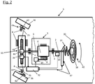
- FIG Fig. 2 such a steering system is shown as an example in a simplified schematic diagram.
- the steering system is installed in a passenger vehicle 5, indicated here in a partial representation, and has the coupling 1 described above, which is fastened with its housing 6 to the body 4.
- the input shaft 2 is arranged on the input side of the clutch 1.
- Input shaft 2 and output shaft 3 are rotatably mounted on the body 4.
- a steering wheel 30 is attached, via which steering movements, as indicated by a rotary movement arrow 40, can be input.
- the steering wheel 30 has additional components 38, which can be an airbag, switching elements and / or display elements. These are connected to the control unit 32 via a cable connection looping around the input shaft several times.
- the cable connection 37 is designed so that it allows steering movements by winding and unwinding.
- the angular range within which the steering wheel 30 can be rotated and the rotation is absorbed by the aforementioned winding and unwinding is referred to below as the winding reserve.
- a sensor 34 which scans the rotational movement of the input shaft and which permanently transmits the rotational angle of the input shaft 2 to the control unit 32 is also provided.
- the end of the output shaft 3 facing away from the clutch 1 acts on a steering drive 44, which is part of the steering actuation mechanism 33.
- the steering actuation mechanism 33 is arranged fixed to the frame on the body 4.
- the steering drive 44 can be a direct steering arrangement in the form of a steering gear or a power steering gear or a superimposed steering arrangement.
- the steering actuation mechanism 33 also contains a toothed rack 41, each end connected to tie rods 35, the other end of the tie rods engaging steering levers 42 which act on the wheel suspension 43 which is rotatably attached to the body 4, in such a way that by the linear movement of the rack 41, a steering angle on the suspension 43 and thus the Wheels 36 is transmitted.
- the steer-by-wire function is implemented by a steer-by-wire drive 39, which is also part of the steering actuation mechanism 33 and acts on the rack 41 and which is bidirectionally connected to the control unit 32. Due to the bidirectional connection, the steer-by-wire drive 39 can be controlled by the control unit 32 on the one hand to set a certain steering angle on the wheels 36, on the other hand it supplies sensor data from a sensor (not shown) contained in the steer-by-wire drive 39 via the set steering angle.
- a normal control mode can be implemented in which the steering wheel angle is the variable determining the steering angle at the wheels 36 and, on the other hand, a steer-by-wire function in which the steering angle at the wheels 36 is specified by the control unit 32 and from the steering wheel angle is completely independent.
- a steer-by-wire function in which the steering angle at the wheels 36 is specified by the control unit 32 and from the steering wheel angle is completely independent.
- a switchover takes place independently of the currently applied steering angle and thus also independently of the steering wheel angle that determines this.
- the switching process essentially consists of the above in connection with Figures 1a to 1c described switching of the clutch 1 from the first switching state (switching position I) to the second switching state (Switch position II). Only after the end of this switching state change does the steer-by-wire function start, controlled by the control unit 32, and move the rack 41 by means of the steer-by-wire drive 39 as a function of the vehicle movement Execution of the driving maneuver a required steering angle.
- the clutch 1 is downshifted from the second switching state (switching position II) to the first switching state (switching position I) by the control unit 32.
- the control unit 32 checks the currently applied steering wheel angle via the sensor 34 and regulates the steering angle by means of the steer-by-wire drive 39 to a steering angle that corresponds to the currently applied steering wheel angle; only then does the clutch 1 change over from switching position I to switching position II (cf. Figures 1a to 1c ). In this way it is ensured that the input shaft 2 and thus the steering wheel 30 are not rotated and coupled to the output shaft 3.
- this process should preferably be carried out when the vehicle is stationary, ideally even when the steering wheel is not actuated, since it can be rotated by plus / minus 10 ° in switch position II.
- the case may arise that when the clutch 1 is in the second switching state, the controllability of the passenger vehicle 5 must be immediately restored by means of the steering wheel 30. This can be the case, for example, after an evasive maneuver using the steer-by-wire function or when the steer-by-wire function fails.
- a synchronization of the steering angle and steering wheel angle must be dispensed with for safety reasons; instead, the switching back to the first switching state of clutch 1 takes place without steering movement of the wheels 36 and without delay. It must be accepted with such an emergency downshift, that after the emergency downshift has taken place, the steering wheel is rotated, but the passenger car 5 remains continuously controllable.
- the steering angle and steering wheel angle can be synchronized by initially controlling the clutch 1 from the first switching state (switching position I) by the control unit 32. is brought into the second switching state (switching position II), the control unit 32 then detects the currently applied steering wheel angle via the sensor 34 and then regulates the steering angle by means of the steer-by-wire drive 39 to a steering angle that corresponds to the currently applied steering wheel angle. If clutch 1 is switched from switching position II to switching position I in this position (cf. Figures 1a to 1c ) the turning of the steering wheel is canceled.
- the winding reserve i.e. the range within which the steering wheel 30 can be turned and the rotation through the aforementioned Winding and unwinding is caught, the maximum possible rotation of the steering wheel 30 in the event of an emergency downshift from the second switching state (switching position II) to the first switching state (switching position I) must also cover.
Landscapes
- Engineering & Computer Science (AREA)
- Transportation (AREA)
- Mechanical Engineering (AREA)
- Chemical & Material Sciences (AREA)
- Combustion & Propulsion (AREA)
- Automation & Control Theory (AREA)
- Human Computer Interaction (AREA)
- Steering Control In Accordance With Driving Conditions (AREA)
- Power Steering Mechanism (AREA)
Description
- Die Erfindung betrifft ein Lenksystem gemäß dem Oberbegriff des Patentanspruchs 1.
- Lenkanordnungen sind im Allgemeinen derart konfiguriert, dass ein Lenkelement und ein Lenkbetätigungsmechanismus zu jeder Zeit mechanisch miteinander gekoppelt sind. In den letzten Jahren wurde jedoch eine Vielzahl von Lenksystemen vorgeschlagen und realisiert, bei denen zwischen einem gekoppelten Zustand, in dem ein Lenkelement und ein Lenkbetätigungsmechanismus mechanisch miteinander gekoppelt sind, und einem entkoppelten Zustand, in dem das Lenkelement und der Lenkbetätigungsmechanismus mechanisch voneinander entkoppelt sind, umgeschaltet werden kann. Im entkoppelten Zustand werden entweder Drehbewegungen am Lenkelement über Sensoren abgetastet und über ein Steuersystem und von diesem angesteuerte Aktoren in eine Lenkbewegung des Lenkbetätigungsmechanismus umgesetzt oder das Steuersystem generiert aufgrund von Sensordaten selbständig Lenkbefehle und setzt diese durch Ansteuerung der Aktoren in eine Lenkbewegung des Lenkbetätigungsmechanismus um. Der entkoppelte Zustand wird üblicherweise als Steer-by-Wire Konfiguration bezeichnet und kommt zum Einsatz, wenn zum Beispiel die Lenkcharakteristik geschwindigkeitsabhängig geändert werden soll, wenn ein Lenkeingriff in vom Fahrer nicht beherrschbaren Situationen, zum Beispiel zur Vermeidung von Unfällen, vorgenommen werden muss oder wenn zur Komfortsteigerung ein Fahrmanöver selbständig von dem Fahrzeug ausgeführt werden soll, wie zum Beispiel ein automatisches Einparken in eine Parklücke.
- Im Allgemeinen werden in den Fällen, in denen die Steer-by-Wire Konfiguration aktiv ist, die tatsächlichen Lenkbewegungen des Fahrzeugs als Feedback für den Fahrer über Servoantriebe in eine Stellung des Lenkelementes umgesetzt.
- Ein Lenksystem der vorstehend genannten Art, das über eine Kupplungsanordnung zum bedarfsweisen Verbinden eines Lenkelementes mit einem Lenkbetätigungsmechanismus verfügt, ist beispielsweise in der
EP 3 202 641 A1 sowie derUS 2017/0217475 A1 beschrieben. Dort wird vorgeschlagen, ein Lenksystem bereitzustellen, das einen ersten Teil einer Lenkwelle, der mit einem Lenkelement verbunden ist, mittels einer schaltbaren Kupplung mit einem zweiten Teil einer Lenkwelle, der mit einem Lenkbetätigungsmechanismus verbunden ist, bedarfsweise koppelt oder entkoppelt. Im entkoppelten Normalbetrieb erfolgt das Lenken mittels einer Steuereinheit auf der Basis von Sensordaten, wobei die Steuereinheit den Lenkeinschlag mittels eines von ihr angesteuerten Motors, der auf den Lenkbetätigungsmechanismus wirkt, einstellt. Auf den ersten Teil der Lenkwelle, der mit dem Lenkelement verbunden ist, wirkt eine Feedback-Einheit in Form eines von der Steuereinheit auf der Basis von Sensordaten gesteuerten Servoantriebs, wodurch der das Lenkelement betätigenden Person ein Lenkgefühl vermittelt wird. - Diese der Rückmeldung in Form einer Kraftrückkopplung dienenden Servoantriebe sind jedoch teuer und benötigen einen erheblichen Bauraum. Es besteht daher der Wunsch nach einer einfachen kostengünstigen Lösung.
- Aus der
WO 2016/023691 A1 ist eine gattungsgemäße Fahrzeug-Lenkung bekannt. Aus derDE 10 2007 043 135 A1 ist ein Fahrzeuglenksystem sowie ein Verfahren zur Ansteuerung eines Fahrzeuglenksystems bekannt. - Ausgehend von dem vorstehend genannten Stand der Technik ist es Aufgabe der Erfindung, unter Vermeidung der vorstehend genannten Nachteile, insbesondere unter Verzicht auf eine aktive Rückmeldeeinheit, ein Lenksystem anzugeben, das von einer Steuereinheit gesteuerte Lenkeingriffe erlaubt, ohne dass das Entkoppeln des Lenkelementes vom Lenkbetätigungsmechanismus für die das Lenkelement betätigenden Person als abrupt widerstandslos betätigbares Lenkelement spürbar wird.
- Die Aufgabe ist durch die Merkmale des Anspruchs 1 gelöst. Vorteilhafte Ausgestaltungen sind in den abhängigen Ansprüchen offenbart.
- Ausgegangen wird von einem Lenksystem für ein Fahrzeug, umfassend eine Eingangswelle, über die eine Lenkkraft von einem Lenkelement eingebbar ist, eine Ausgangswelle, die auf einen Lenkbetätigungsmechanismus wirkt, eine Kupplung, um die Eingangswelle und die Ausgangswelle miteinander zu verbinden und voneinander zu trennen und wenigstens einen Aktor, mittels dem die Kupplung antreibbar ist, um die Eingangswelle und die Ausgangswelle miteinander zu koppeln und zu entkoppeln. Derartige Anordnungen sind in Verbindung mit Steer-by-Wire Konfiguration bekannt und schaffen die Voraussetzung, dass die Ausgangswelle im entkoppelten Zustand relativ zur Eingangswelle unabhängig drehbar ist, derart, dass ein von einer Steuereinheit steuerbarer Steer-by-Wire Antrieb gesteuert durch eine Steuereinheit auf den Lenkbetätigungsmechanismus den Lenkwinkel bestimmend einwirkt. Bei derartigen Lenksystemen ist üblicherweise eine Sicherheitsfunktion vorgesehen, auf die das Lenksystem bei Ausfall der Steer-by-Wire Funktion zurückfallen kann und bei der die Eingangswelle und die Ausgangswelle drehfest gekoppelt sind.
- Bei der erwähnten Steuereinheit handelt es sich wie heute üblich um eine rechnergestützte Steuereinheit, die über Sensoren Daten ermittelt, diese programmgestützt verarbeitet und in Abhängigkeit von den Verarbeitungsergebnissen Aktoren ansteuert. Nachdem derartige Steuereinheiten allgemein bekannt sind, erübrigt es sich auf deren Aufbau näher einzugehen.
- Zur Lösung der Aufgabe wird vorgeschlagen das Lenksystem so auszubilden, dass die Kupplung mittels des durch die Steuereinheit gesteuerten wenigstens einen Aktors in zwei diskrete Schaltzustände bringbar ist, wobei die Kupplung im ersten Schaltzustand die Eingangswelle und die Ausgangswelle drehfest miteinander verbindet und im zweiten Schaltzustand die Eingangswelle einerseits von der Ausgangswelle entkoppelt und andererseits die Eingangswelle durch direkte oder indirekte Kopplung relativ zu einem feststehenden Teil des Fahrzeug, zum Beispiel zur Fahrzeugkarosserie festlegt. Weiter wird vorgeschlagen, dass die Ausgangswelle nur im zweiten Schaltzustand unabhängig von der Eingangswelle mittels des Steer-by-Wire Antriebs gesteuert durch die Steuereinheit drehbar ist. Durch das vorgeschlagene Lenksystem wird vorteilhaft eine Steer-by-Wire Funktion ermöglicht, bei der eine Rückmeldung mittels eines Servoantriebs kosten- und platzeinsparend entfällt und dennoch eine Rückmeldung in Form einer Kraftrückkopplung gegeben ist. Insbesondere wird erreicht, dass das Lenkrad zu keinem Zeitpunkt lose drehbar ist, so dass ein Unsicherheitsgefühl für den Fahrer vorteilhaft vermieden wird.
- Erfindungsgemäß ist die direkte oder indirekte Kopplung zwischen der Eingangswelle und dem feststehenden Teil des Fahrzeug im zweiten Schaltzustand mittels wenigstens eines zwischen der Eingangswelle und dem feststehenden Teil des Fahrzeug wirkenden Federmechanismus drehweich ausgebildet, derart, dass die Eingangswelle mittels des mit ihr verbundenen Lenkelementes um einen vorgegebenen Winkelbetrag in beide Drehrichtungen gegen die Kraft des wenigstens einen Federelementes drehbar ist und bei Drehung über diesen Winkelbetrag hinaus an mit dem feststehenden Teil des Fahrzeug direkt oder indirekt verbundene Anschläge gelangt. Durch diese Ausgestaltung wird eine vom Drehwinkel der Eingangswelle und damit des Lenkelementes, zum Beispiel eines Lenkrades, abhängige Kraftrückmeldung erreicht, wenn die Steer-by-Wire Funktion eingeschaltet wird oder anliegt. Dies vermittelt dem Fahrer deutlich mehr Sicherheit, als ein abrupt blockiertes oder gar ein lose drehbares Lenkelement. Besonders bewährt hat es sich, wenn der vorgegebene Winkelbetrag größer als 5° und kleiner als 30°, bevorzugt größer als 5° und kleiner als 20°, höchst bevorzugt größer als 5° und kleiner als 15° ist.
- Um vorteilhaft sicherzustellen, dass das Lenkelement zu keinem Zeitpunkt lose drehbar ist, ist die Kupplung so ausgebildet, dass sie beim Übergang vom ersten Schaltzustand in den zweiten Schaltzustand in einem während des Umschaltens dynamisch durchlaufenen Zwischenbereich zwischen dem ersten Schaltzustand und dem zweiten Schaltzustand die Eingangswelle und die Ausgangswelle drehfest miteinander verbindet und die Eingangswelle relativ zu einem feststehenden Teil des Fahrzeug, zum Beispiel zur Fahrzeugkarosserie festlegt, derart, dass die Eingangswelle zu keinem Zeitpunkt frei drehbar ist. Das Durchlaufen des Übergangsbereiches ist dabei vorteilhaft zeitlich so bemessen, dass bei einem Schaltvorgang von dem ersten Schaltzustand in den zweiten Schaltzustand, bei Anliegen einer Lenkkraft an der Eingangswelle, die mit der Fahrzeugkarosserie gekoppelte Eingangswelle nicht an die Anschläge gelangt. Auf diese Weise wird die Kraftrückkopplung auf die Eingangswelle beim Umschalten von der Direktsteuerung auf die Steer-by-Wire Funktion im Wesentlichen ohne unkomfortable Kraftsprünge am Lenkelement, zum Beispiel dem Lenkrad gestaltet.
- In weiterer Ausgestaltung des Lenksystems ist es von Vorteil, dass im Normalbetrieb die Steuereinheit beim Wechsel von dem zweiten Schaltzustand in den ersten Schaltzustand die Winkelstellung der Ausgangswelle auf die Winkelstellung der Eingangswelle synchronisiert, derart, dass der Steer-byWire Antrieb, gesteuert durch die Steuereinheit, den Lenkbetätigungsmechanismus auf die mittels wenigstens eines Sensors ermittelte Winkelstellung der Eingangswelle einstellt und dass dann die Steuereinheit durch Ansteuern des wenigstens einen Aktors die Kupplung in den ersten Schaltzustand bringt. Durch diese Maßnahme kann der Lenkbetätigungsmechanismus und mit ihm zum Beispiel die Räder eines Fahrzeugs, durch die Steuereinheit mittels des Steer-by-Wire Antriebs auf die Stellung eingeregelt werden, die durch die Winkelstellung der Eingangswelle vorgegeben ist, sodass ein verdrehtes Koppeln der Eingangswelle mit der Ausgangswelle sicher verhindert wird. Es ist dabei von Vorteil, wenn das Umschalten von dem zweiten Schaltzustand in den ersten Schaltzustand bei Stillstand der Eingangswelle und bevorzugt des Fahrzeugs erfolgt.
- Um bei Anliegen der Steer-by-Wire Funktion eine Absicherung bei deren Ausfall bereitzuhalten ist es von Vorteil, eine Notumschaltung von dem zweiten Schaltzustand in den ersten Schaltzustand vorzusehen, wobei nach Auslösen der Notumschaltung die Steuereinheit, unabhängig von der Winkelstellung der Eingangswelle, durch Ansteuern des wenigstens einen Aktors die Kupplung in den ersten Schaltzustand bringt. Durch diese Maßnahme wird die unterbrechungsfreie Lenkbarkeit des Fahrzeugs auch bei Systemausfall gewährleistet.
- Zur Ausgestaltung der Kupplung, die die jeweiligen Verbindungen in dem ersten Schaltzustand oder dem zweiten Schaltzustand herstellt, kann neben einer formschlüssigen Verbindung eine Verbindung per Reibschluss oder per Kraftschluss vorgesehen sein. Selbstverständlich ist auch eine Mischung dieser Verbindungsmöglichkeiten denkbar, zum Beispiel indem die Kopplung zwischen Eingangswelle und Ausgangswelle im ersten Schaltzustand formschlüssig erfolgt und die direkte oder indirekte Verbindung zwischen Eingangswelle und einem feststehenden Teil des Fahrzeug im zweiten Schaltzustand im Wege eines Reibschlusses oder eines Kraftschlusses.
- Zur vorteilhaften Ausgestaltung der Kupplung ist vorgesehen, dass diese wenigstens ein Schaltelement aufweist, wobei die Kupplung mittels des wenigstens einen Schaltelementes im ersten Schaltzustand die Eingangswelle und die Ausgangswelle drehfest miteinander verbindet und im zweiten Schaltzustand die Eingangswelle einerseits von der Ausgangswelle entkoppelt und andererseits mittels des wenigstens einen Schaltelementes die Eingangswelle relativ zu einem feststehenden Teil des Fahrzeug, zum Beispiel der Fahrzeugkarosserie festlegt. Das Vorsehen eines einzelnen Schaltelementes, das alle Aufgaben erfüllt, ist aus Kostengründen vorzuziehen, es kann aber auch die konstruktive Notwendigkeit bestehen, für die Kupplung zum Beispiel zwei Schaltelemente vorzusehen, wobei das erste Schaltelement im ersten Schaltzustand die Eingangswelle und die Ausgangswelle drehfest miteinander verbindet und im zweiten Schaltzustand die Verbindung zwischen Eingangswelle und die Ausgangswelle löst und das zweite Schaltelement im zweiten Schaltzustand die Eingangswelle relativ zu einem feststehenden Teil des Fahrzeug festlegt und im ersten Schaltzustand diese Verbindung löst.
- Zur Betätigung des wenigstens einen Schaltelementes ist vorteilhaft wenigstens ein Aktor vorgesehen, wobei dieser einen kraftentfaltenden Antrieb aufweist der einer der Gruppen elektrischer Antrieb, mechanischer Antrieb, pneumatischer Antrieb, hydraulischer Antrieb, pyrotechnischer Antrieb oder einer beliebigen Mischform dieser Antriebe angehört. Selbstverständlich können diese Antriebsformen untereinander kombiniert werden. So ist es denkbar im allgemeinen Fall einen elektromagnetischen oder elektromotorischen Antrieb oder wenn entsprechende Kraftquellen vorhanden sind einen pneumatischen oder einen hydraulischen Antrieb vorzusehen, für eine im Wesentlichen verzögerungsfreie und sichere Notumschaltung vom zweiten Schaltzustand in den ersten Schaltzustand kann aber auch zusätzlich ein pyrotechnischer Antrieb vorteilhaft sein.
- Weitere Ausgestaltungen und Vorteile der Erfindung werden nachfolgend anhand der Zeichnungen näher erläutert. Es zeigen:
- Fig. 1a bis 1c
- eine Prinzipdarstellung der Kupplungsanordnung des Lenksystems in Schnittdarstellung; und
- Fig. 2
- eine Prinzipdarstellung des Lenksystems in einem Personenkraftwagen.
- Für die nachfolgende Beschreibung ist angenommen, dass das erfindungsgemäße Lenksystem in einen Personenkraftwagen eingebaut ist. Als Kernstück enthält das Lenksystem eine Kupplung, deren Aufbau und Funktionsweise zunächst anhand des in
Fig. 1a bis Fig. 1c dargestellten Beispiels beschrieben ist. Die Ausgestaltung ist dabei stark vereinfacht dargestellt und zeigt nur eine von einer Vielzahl von Realisierungsmöglichkeiten. Dargestellt ist die Anordnung in drei unterschiedlichen Phasen einer Umschaltung von einem ersten Schaltzustand in einen zweiten Schaltzustand. Für gleiche Teile sind gleiche Bezugszeichen verwendet. - Gemäß den Darstellungen in
Fig. 1a bis Fig. 1c dient die Kupplung 1 dazu, eine Eingangswelle 2 in einem ersten Schaltzustand mit einer Ausgangswelle 3 zu verbinden und in einem zweiten Schaltzustand die Verbindung zu lösen und stattdessen die Eingangswelle 2 relativ zur Karosserie 4 des Personenkraftwagens 5 (Fig. 2 ) festzulegen. Die Kupplung 1 weist ein zylinderförmiges Gehäuse 6 auf, das gestellfest an der Karosserie 4 angeordnet ist. In dem Gehäuse 6 sind koaxial zu dessen Mittelachse 7 die Eingangswelle 2 mittels eines ersten Lagers 13 und die Ausgangswelle 3 mittels eines zweiten Lagers 14 drehbar gelagert. Die Mittelachse 7 ist damit auch Drehachse der Eingangswelle 2 und der Ausgangswelle 3. - An ihrem der Eingangswelle 2 zugewandten Ende 8 weist die Ausgangswelle 3 eine Ausnehmung 9 auf, in der das der Ausgangswelle 3 zugewandte Wellenende 10 der Eingangswelle 2 mittels eines dritten Lagers 15 drehbar gelagert ist. Zu ihrem offenen Ende hin ist die Ausnehmung 9 mit einer Innenverzahnung 25 ausgestattet, die, wie unten näher ausgeführt, mit einer Schalthülse 12 zusammenwirkt.
- Die Schalthülse 12 ist auf der Eingangswelle 2, zwischen der Lagerung der Eingangswelle 2 in der Ausgangswelle 3 und ihrer Lagerung in dem Gehäuse 6, axial verschiebbar und drehfest angeordnet. Hierzu ist die Eingangswelle 2 in diesem Bereich mit einer axial verlaufenden Außenverzahnung 11 ausgestattet, die mit einer axial verlaufenden Innenverzahnung (in der Darstellung nicht sichtbar) der Schalthülse 12 korrespondiert und zusammenwirkt. Weiter weist die Schalthülse 12 eine axial verlaufende Außenverzahnung 16 auf, die hinsichtlich ihrer axialen Erstreckung etwa in der Mitte durch eine umlaufende Schaltkulisse 17 in zwei Hälften geteilt ist. In die Schaltkulisse 17 greift ein Schaltfinger 18 ein der, betätigt von einem Aktor 19, parallel zur Mittelachse 7 verschiebbar ist und damit die Schalthülse 12 axial verschiebt. Der Außendurchmesser der Schalthülse 12 und deren Außenverzahnung 16 korrespondieren mit dem Innendurchmesser der Ausnehmung 9 und deren Innenverzahnung 25, derart dass die Schalthülse 12 bei entsprechender axialer Stellung in die Ausgangswelle 3 drehfest eingreift.
- Als weiteres Element ist in dem Gehäuse 6 der Kupplung 1 eine zylinderförmige Koppelhülse 20 koaxial zur Mittelachse 7 gelagert. Die Koppelhülse 20 ist durch umlaufende Anformungen 21, ihre radiale Position betreffend im Innern des Gehäuses 6 gehalten und so angeordnet dass sie einen axialen Abstand zum Ende 8 der Ausgangswelle aufweist, der kleiner ist, als die axiale Erstreckung der Schalthülse 12. Die Anformungen 21 und die Mandelfläche der Koppelhülse 20 bilden ein Gleitlager aus, derart, dass die Koppelhülse 20 im Innern des Gehäuses 6 um die Mittelachse 7 drehbar ist. Weiter weist die Koppelhülse 20 an ihrem dem ersten Lager 13 zugewandten Ende eine über einen definierten Winkelbereich auf ihrer Außenseite in Umfangsrichtung verlaufende Nut 22 auf, in die ein das Gehäuse 6 durchsetzender Stift 23 eingreift. Auf diese Weise ist die Koppelhülse 20 in axialer Richtung im Gehäuse 6 fixiert und in Umfangsrichtung innerhalb des durch die Längserstreckung der Nut 22 definierten Winkelbereichs verdrehbar. Der Winkelbereich ist dabei so gewählt, dass die Koppelhülse ausgehend von einer Mittelposition um einen Winkelbetrag von ca. plus/minus 10° im Gehäuse 6 drehbar ist. Weiter weist die Koppelhülse 20 eine Innenverzahnung 26 auf, wobei der Innendurchmesser der Koppelhülse 20 und deren Innenverzahnung 26 mit dem Außendurchmesser der Schalthülse 12 und deren Außenverzahnung 16 korrespondieren, derart dass die Schalthülse 12 bei entsprechender axialer Stellung in die Koppelhülse 20 drehfest eingreift.
- Zwischen den Anformungen 21 im Gehäuse 6 sind Federelemente 24 angeordnet, die mit einem ihrer beiden Enden an dem Gehäuse 6 und mit ihrem anderen Ende an der Mandelfläche der Koppelhülse 20 angreifen. Auf diese Weise wird die Koppelhülse 20 hinsichtlich ihres Drehwinkels im nicht mit der Eingangswelle 2 gekoppelten Zustand in beide Drehrichtungen gefedert in der vorstehend erwähnten Mittelposition gehalten. Die Koppelhülse 20 ist somit gegen die Kraft der Federelemente 24, ausgehend von der Mittelposition um einen Betrag von ca. plus/minus 10° im Gehäuse 6 drehbar und gelangt bei einem Drehwinkel größer plus/minus 10° an durch die Längserstreckung der Nut 22 gegebenen Anschläge.
- Ausgehend vom vorstehend beschriebenen Aufbau der Kupplung 1 soll nun in Verbindung mit den Darstellungen gemäß
Fig. 1a bis Fig. 1c ein Schaltvorgang der Kupplung näher beschrieben werden. Ausgehend vonFig. 1a in der die Kupplung in ihrem ersten Schaltzustand (erste Schaltstellung I) dargestellt ist, erfolgt die Umschaltung über einen im Laufe des Schaltvorganges dynamisch durchlaufenen Zwischenzustand Z, der inFig. 1b gezeigt ist und endet in einem inFig. 1c gezeigten zweiten Schaltzustand (zweiten Schaltstellung II). Die Schaltstellungen I und II sind in den Darstellungen durch strichpunktierte Linien angedeutet, dazwischen liegt der Zwischenzustand Z. - Gemäß der Darstellung in
Fig. 1a befindet sich der Schaltfinger 18 in der mit I bezeichneten ersten Schaltstellung. In dieser Schaltstellung I ist die mittels des Aktors 19 über den Schaltfinger 18 und die Schaltkulisse 17 axial bewegbare Schaltmuffe in ihrer in der Darstellung linken Endstellung. Dabei greift die Außenverzahnung 16 der Schalthülse 12 in die korrespondiere Innenverzahnung 25 der Ausnehmung 9 ein. Andererseits ist die Schalthülse 12 über ihre Innenverzahnung (in der Darstellung nicht sichtbar) und die korrespondierende Außenverzahnung 11 der Eingangswelle 2 drehfest mit dieser verbunden. Ein gemäß dem Drehmomentpfeil 27 auf die Eingangswelle 2 aufgebrachtes Drehmoment wird demnach 1:1 auf die Ausgangswelle 3 übertragen, wie dies durch den Drehmomentpfeil 28 angedeutet ist. Wird also mittels eines Lenkrades 30 direkt oder indirekt ein Drehmoment gemäß dem Drehmomentpfeil 27 auf die Eingangswelle 2 aufgebracht, dreht sich die Ausgangswelle 3 im Verhältnis 1:1 mit. Durch die Betätigungskraft, die für die Betätigung des von der Ausgangswelle 3 angetriebenen Lenkbetätigungsmechanismus 33 (Fig. 2 ) erforderlich ist, wird der lenkenden Person (nicht dargestellt) ein natürliches Lenkgefühl vermittelt. - Wird nun der Aktor 19 durch die Steuereinheit 32 (
Fig. 2 ) mit einem Schaltsignal beaufschlagt, bewegt dieser den Schaltfinger 18 und damit die Schalthülse 12 in der Darstellung gemäßFig. 1b nach rechts, wie dies durch den Bewegungspfeil 31a angedeutet ist. Dabei durchläuft die Anordnung einen Zwischenzustand Z, in welchem die Eingangswelle 2 einerseits über ihre Außenverzahnung 11, die korrespondierende Innenverzahnung der Schalthülse (in der Darstellung nicht sichtbar), die Außenverzahnung 16 der Schalthülse 12 und die korrespondiere Innenverzahnung 25 der Ausnehmung 9 mit der Ausgangswelle 3 verbunden ist und andererseits über die Außenverzahnung 11, die korrespondierende Innenverzahnung (in der Darstellung nicht sichtbar) der Schalthülse 12, die Außenverzahnung 16 der Schalthülse 12 und die korrespondiere Innenverzahnung 26 der Koppelhülse 20 mit den Federelementen 24 und damit über das Gehäuse 6 mit der Karosserie 4. - Durch diese doppelte Kopplung der Eingangswelle 2, sowohl mit der Ausgangswelle 3, als auch drehweich mit der Karosserie 4 wird erreicht, dass die Eingangswelle 3 und damit das Lenkrad 31 zu keinem Zeitpunkt frei drehbar ist oder zum Zeitpunkt des Umschaltens von der ersten Schaltstellung I in die zweite Schaltstellung II abrupt blockiert. Um ein abruptes Blockieren zu vermeiden ist die Schaltzeit für das Durchlaufen des Zwischenzustandes Z so bemessen, dass in dieser Zeit das Lenkrad nicht so weit gedreht werden kann, dass die Koppelhülse 20 von ihrer Mittelposition bis zum Ende der Nut 22 gedreht würde, also an den Anschlag gelangt. Auf diese Weise bleibt ein nahezu natürliches Lenkgefühl für die lenkende Person (nicht dargestellt) erhalten, weil der für die Betätigung des Lenkbetätigungsmechanismus 33 (
Fig. 2 ) erforderlichen Kraft lediglich eine zusätzliche, mit zunehmendem Drehwinkel des Lenkrades 30 ansteigende Kraft überlagert wird. - Mit zunehmender Bewegung der Schalthülse 12 in Richtung auf die zweite Schaltstellung II gelangt die Außenverzahnung 16 der Schalthülse 12 außer Eingriff mit der Innenverzahnung 25 in der Ausnehmung 9. So dass bei Drehen der Eingangswelle 2 (des Lenkrades 30) das Lenkgefühl, das der lenkenden Person (nicht dargestellt) vermittelt wird, alleine durch die Kraft der Federelemente 24 bestimmt ist. Der Zeitpunkt zu dem die Schalthülse 12 außer Eingriff mit der Ausgangswelle 3 gelangt, wird durch das Maß bestimmt, das die Schalthülse 12 in ihrer axialen Ausdehnung größer ist als der axiale Abstand von Ausgangswelle 3 und Koppelhülse 20. Die drehweiche Kopplung der Eingangswelle 2 mit der Karosserie 4 bleibt so lange bestehen, wie sich die Kupplung 1 in der in
Fig. 1c dargestellten Schaltstellung II befindet. Wird durch eine entsprechende Beaufschlagung des Aktors 19 durch die Steuereinheit 32 (Fig. 2 ) mit einem entsprechenden Schaltsignal ein Umschalten von der zweiten Schaltstellung II in die erste Schaltstellung I initiiert, läuft der vorstehend beschriebene Vorgang wie durch den zweiten Richtungspfeil 31b (Fig. 1c ) angedeutet, in umgekehrter Richtung und Reihenfolge ab. Um Wiederholungen zu vermeiden wird auf eine detaillierte Beschreibung dieses Rückschaltvorgangs verzichtet und stattdessen auf die vorstehenden Ausführungen verwiesen. - Um das Zusammenwirken der Kupplung 1 mit den übrigen Komponenten des Lenksystems deutlich zu machen, ist in
Fig. 2 ein solches Lenksystem in vereinfachter Prinzipdarstellung beispielhaft gezeigt. Das Lenksystem ist, wie bereits oben erwähnt, in einem hier in Teildarstellung angedeuteten Personenkraftwagen 5 eingebaut und weist die vorstehend beschriebene Kupplung 1 auf, die mit ihrem Gehäuse 6 an der Karosserie 4 befestigt ist. An der Eingangsseite der Kupplung 1 ist die Eingangswelle 2 angeordnet. Auf der Ausgangsseite die Ausgangswellen 3. Eingangswelle 2 und Ausgangswelle 3 sind an der Karosserie 4 drehbar gelagert. An dem der Kupplung 1 abgewandten Ende der Eingangswelle 2 ist ein Lenkrad 30 angebracht, über das Lenkbewegungen, wie durch einen Drehbewegungspfeil 40 angedeutet, eingegeben werden können. Das Lenkrad 30 verfügt über Zusatzkomponenten 38, dabei kann es sich um einen Airbag, Schaltelemente und/ oder Anzeigeelemente handeln. Diese sind über eine die Eingangswelle mehrfach umschlingende Kabelverbindung an die Steuereinheit 32 angeschlossen. Die Kabelverbindung 37 ist dabei so ausgeführt, dass sie Lenkbewegungen durch Aufwickeln und Abwickeln zulässt. Der Winkelbereich, innerhalb dessen das Lenkrad 30 gedreht werden kann und die Drehung durch das erwähnte Aufwickeln und Abwickeln aufgefangen wird, ist nachfolgend als Wickelreserve bezeichnet. Weiter ist ein die Drehbewegung der Eingangswelle abtastender Sensor 34 vorgesehen, der den Drehwinkel der Eingangswelle 2 permanent an die Steuereinheit 32 übermittelt. - Die Ausgangswelle 3 wirkt mit ihrem der Kupplung 1 abgewandten Ende auf einen Lenktrieb 44, der Teil des Lenkbetätigungsmechanismus 33 ist. Der Lenkbetätigungsmechanismus 33 ist an der Karosserie 4 gestellfest angeordnet. Bei dem Lenktrieb 44 kann es sich um eine direkte Lenkanordnung in Form eines Lenkgetriebes oder um ein Servolenkgetriebe oder um eine Überlagerungslenkanordnung handeln. Weiter enthält der Lenkbetätigungsmechanismus 33 im gewählten Beispiel eine Zahnstange 41, die jeweils endseitig mit Spurstangen 35 verbunden ist, wobei die Spurstangen mit ihrem jeweils anderen Ende an Lenkhebeln 42 angreifen, die auf die an der Karosserie 4 drehbar befestigte Radaufhängung 43 wirken, derart, dass durch die Linearbewegung der Zahnstange 41 ein Lenkwinkel auf die Radaufhängung 43 und damit die Räder 36 übertragen wird. Die Steer-by-Wire Funktion wird im gewählten Beispiel durch einen Steer-by-Wire Antrieb 39 realisiert, der ebenfalls Teil des Lenkbetätigungsmechanismus 33 ist und auf die Zahnstange 41 wirkt und der bidirektional mit der Steuereinheit 32 verbunden ist. Durch die bidirektionale Verbindung ist der Steer-by-Wire Antrieb 39 einerseits von der Steuereinheit 32 ansteuerbar um einen bestimmten Lenkwinkel an den Rädern 36 einzustellen, andererseits liefert er von einem in dem Steer-by-Wire Antrieb 39 enthaltenen Sensor (nicht dargestellt) Sensordaten über den eingestellten Lenkwinkel.
- Wie eingangs bereits ausgeführt, soll mittels des Lenksystems gemäß dem Beispiel nach
Fig. 2 einerseits ein Normal-Steuerbetrieb realisiert werden, bei dem der Lenkradwinkel die den Lenkwinkel an den Rädern 36 bestimmende Größe ist und andererseits eine Steer-by-Wire Funktion, bei welcher der Lenkwinkel an den Rädern 36 mittels der Steuereinheit 32 vorgegeben wird und von dem Lenkradwinkel völlig unabhängig ist. Hierzu sind beim Wechsel vom Normal-Steuerbetrieb in die Steer-by-Wire Funktion und umgekehrt von der Steer-by-Wire Funktion zurück in den Normal-Steuerbetrieb einige Bedingungen zu erfüllen. Für die nachfolgenden Ausführungen ist angenommen, dass die Umschaltung vom Normal-Steuerbetrieb in die Steer-by-Wire Funktion nur dann erfolgt, wenn entweder ein automatisiertes Fahrmanöver ausgeführt werden soll, um zum Beispiel das Fahrzeug automatisch in eine Parklücke einzuparken oder wenn in einer Notsituation ein Lenkeingriff in vom Fahrer nicht beherrschbaren Situationen durch die Steuereinheit 32 aufgrund von vorliegenden Sensordaten vorgenommen werden muss, um zum Beispiel einen Unfall zu vermeiden oder dessen Folgen zu mildern. - Unter der Annahme, dass sich das Lenksystem im Normal-Steuerbetrieb befindet, erfolgt eine Umschaltung unabhängig von dem augenblicklich anliegenden Lenkwinkel und damit auch unabhängig von dem diesen bestimmenden Lenkradwinkel. Der Umschaltvorgang besteht im Wesentlichen im vorstehend in Verbindung mit
Fig. 1a bis Fig. 1c beschriebenen Umschalten der Kupplung 1 von dem ersten Schaltzustand (Schaltstellung I) in den zweiten Schaltzustand (Schaltstellung II). Erst nach Beendigung dieses Schaltzustandswechsels setzt, gesteuert durch die Steuereinheit 32 die Steer-by-Wire Funktion ein und bewegt mittels des Steer-by-Wire Antriebs 39 die Zahnstange 41 in Abhängigkeit von der Fahrzeugbewegung, stellt also in Abhängigkeit von der Fahrzeugbewegung den für die Ausführung des Fahrmanövers erforderlichen Lenkwinkel ein. - Ist das Fahrmanöver ausgeführt, erfolgt die Rückschaltung der Kupplung 1 vom zweiten Schaltzustand (Schaltstellung II) in den ersten Schaltzustand (Schaltstellung I) durch die Steuereinheit 32. Hier sind zwei Fälle zu unterscheiden, eine reguläre Rückschaltung und eine Notrückschaltung. Im Falle einer regulären Rückschaltung überprüft die Steuereinheit 32 über den Sensor 34 den augenblicklich anliegenden Lenkradwinkel und regelt den Lenkwinkel mittels des Steer-by-Wire Antriebs 39 auf einen Lenkwinkel ein, der dem augenblicklich anliegenden Lenkradwinkel entspricht, erst dann erfolgt die Umschaltung der Kupplung 1 von Schaltstellung I in Schaltstellung II (vgl.
Fig. 1a bis Fig. 1c ). Auf diese Weise ist sichergestellt, dass die Eingangswelle 2 und damit das Lenkrad 30 nicht verdreht mit der Ausgangswelle 3 gekoppelt wird. Da während der Synchronisation von Lenkwinkel und Lenkradwinkel eine Lenkbewegung der Räder 36 erfolgt, ist dieser Vorgang bevorzugt im Fahrzeugstillstand auszuführen, idealerweise auch bei nicht betätigtem Lenkrad, da dieses ja in Schaltstellung II um plus/minus 10° drehbar ist. - Wie vorstehend erwähnt kann der Fall eintreten, dass bei im zweiten Schaltzustand befindlicher Kupplung 1 die Steuerbarkeit des Personenkraftwagens 5 mittel des Lenkrades 30 augenblicklich wieder hergestellt werden muss. Dies kann beispielsweise nach einem Ausweichmanöver mittels der Steer-by-Wire Funktion der Fall sein oder dann wenn die Steer-by-Wire Funktion ausfällt. Im Falle einer solchen Notrückschaltung vom zweiten Schaltzustand (Schaltstellung II) in den ersten Schaltzustand (Schaltstellung I) muss aus Sicherheitsgründen auf eine Synchronisation von Lenkwinkel und Lenkradwinkel verzichtet werden, statt dessen erfolgt die Rückschaltung auf den ersten Schaltzustand der Kupplung 1 ohne Lenkbewegung der Räder 36 und ohne Zeitverzug. Es muss zwar bei einer solchen Notrückschaltung in Kauf genommen werden, dass nach erfolgter Notrückschaltung das Lenkrad verdreht ist, der Personenkraftwagen 5 bleibt aber durchgängig steuerbar.
- Selbstverständlich kann nach einer Notrückschaltung, wie sie vorstehend beschrieben ist, beim nächsten Stillstand des Personenkraftwagens 5 und gegebenenfalls nach Fortfall der Störung eine Synchronisation von Lenkwinkel und Lenkradwinkel durchgeführt werden, indem die Kupplung 1 zunächst gesteuert durch die Steuereinheit 32 vom ersten Schaltzustand (Schaltstellung I) in den zweiten Schaltzustand (Schaltstellung II) gebracht wird, die Steuereinheit 32 sodann über den Sensor 34 den augenblicklich anliegenden Lenkradwinkel erfasst und dann den Lenkwinkel mittels des Steer-by-Wire Antriebs 39 auf einen Lenkwinkel einregelt, der dem augenblicklich anliegenden Lenkradwinkel entspricht. Erfolgt in dieser Stellung die Umschaltung der Kupplung 1 von Schaltstellung II auf Schaltstellung I (vgl.
Fig. 1a bis Fig. 1c ) ist die Verdrehung des Lenkrades aufgehoben. - Im Hinblick auf die Notrückschaltung vom zweiten Schaltzustand (Schaltstellung II) in den ersten Schaltzustand (Schaltstellung I) ist hinsichtlich der Auslegung der Wickelreserve zu beachten, dass die Wickelreserve, also der Bereichs innerhalb dessen das Lenkrad 30 gedreht werden kann und die Drehung durch das erwähnte Aufwickeln und Abwickeln aufgefangen wird, die maximal mögliche Verdrehung des Lenkrades 30 bei einer Notrückschaltung vom zweiten Schaltzustand (Schaltstellung II) in den ersten Schaltzustand (Schaltstellung I) mit abdecken muss.
Claims (9)
- Lenksystem für ein Fahrzeug, umfassend eine Eingangswelle (2), über die eine Lenkkraft von einem Lenkelement eingegeben wird, eine Ausgangswelle (3), die auf einen Lenkbetätigungsmechanismus wirkt, eine Kupplung (1), um die Eingangswelle (2) und die Ausgangswelle (3) miteinander zu verbinden und voneinander zu trennen und wenigstens einen Aktor (19), mittels dem die Kupplung (1) antreibbar ist, um die Eingangswelle (2) und die Ausgangswelle (3) miteinander zu koppeln und zu entkoppeln, wobei die Ausgangswelle (3) im entkoppelten Zustand relativ zur Eingangswelle (2) unabhängig drehbar ist, derart, dass ein von einer Steuereinheit (32) steuerbarer Steer-by-Wire Antrieb (39) vorgesehen ist, der gesteuert durch die Steuereinheit (32) auf den Lenkbetätigungsmechanismus (33) den Lenkwinkel bestimmend einwirkt und wobei die Eingangswelle (2) und die Ausgangswelle (3) im gekoppelten Zustand drehfest miteinander verbunden sind, wobei das Lenksystem so ausgebildet ist, dass die Kupplung (1) mittels des durch die Steuereinheit (32) gesteuerten wenigstens einen Aktors (19) in zwei diskrete Schaltzustände bringbar ist, wobei die Kupplung (1) im ersten Schaltzustand die Eingangswelle (2) und die Ausgangswelle (3) drehfest miteinander verbindet und im zweiten Schaltzustand die Eingangswelle (2) einerseits von der Ausgangswelle (3) entkoppelt und andererseits die Eingangswelle (2) durch direkte oder indirekte Kopplung relativ zu einem feststehenden Teil des Fahrzeug (5) festlegt, und wobei die Ausgangswelle (3) im zweiten Schaltzustand unabhängig von der Eingangswelle mittels des Steer-by-Wire Antrieb (39) gesteuert durch die Steuereinheit (32) drehbar ist, dadurch gekennzeichnet, dass die direkte oder indirekte Kopplung zwischen der Eingangswelle (2) und dem feststehenden Teil des Fahrzeug (5) im zweiten Schaltzustand mittels wenigstens eines zwischen der Eingangswelle (2) und dem feststehenden Teil des Fahrzeug (5) wirkenden Federmechanismus drehweich ausgebildet ist derart, dass die Eingangswelle (2) mittels des mit ihr verbundenen Lenkelementes um einen vorgegebenen Winkelbetrag in beide Drehrichtungen gegen die Kraft des wenigstens einen Federmechanismus drehbar ist und bei Drehung über diesen Winkelbetrag hinaus an mit dem feststehenden Teil des Fahrzeug (5) direkt oder indirekt verbundene Anschläge gelangt.
- Lenksystem nach Anspruch 1, dadurch gekennzeichnet, dass der vorgegebene Winkelbetrag größer als 5° und kleiner als 15° ist.
- Lenksystem nach Anspruch 1 oder 2, dadurch gekennzeichnet, dass die Kupplung (1) so ausgebildet ist, dass sie beim Übergang vom ersten Schaltzustand in den zweiten Schaltzustand und umgekehrt, in einem während des Umschaltens dynamisch durchlaufenen Zwischenbereich (Z) zwischen dem ersten Schaltzustand und dem zweiten Schaltzustand die Eingangswelle (2) und die Ausgangswelle (3) drehfest miteinander verbindet und die Eingangswelle (2) relativ zu dem feststehenden Teil des Fahrzeug (5) festlegt, derart, dass die Eingangswelle (2) zu keinem Zeitpunkt frei drehbar ist.
- Lenksystem nach Anspruch 3, dadurch gekennzeichnet, dass das Durchlaufen des Zwischenbereichs (Z) zeitlich so bemessen ist, dass bei einem Schaltvorgang von dem ersten Schaltzustand in den zweiten Schaltzustand, bei Anliegen einer Lenkkraft an der Eingangswelle (2) die mit dem feststehenden Teil des Fahrzeug (5) drehweich gekoppelte Eingangswelle (2) nicht an die Anschläge gelangt.
- Lenksystem nach einem der vorhergehenden Ansprüche, dadurch gekennzeichnet, dass im Normalbetrieb die Steuereinheit (32) beim Wechsel von dem zweiten Schaltzustand in den ersten Schaltzustand die Winkelstellung der Ausgangswelle (3) auf die Winkelstellung der Eingangswelle (2) synchronisiert, derart, dass der Steer-by-Wire Antrieb (39), gesteuert durch die Steuereinheit (32), den Lenkbetätigungsmechanismus (33) auf die mittels wenigstens eines Sensors (34) ermittelte Winkelstellung der Eingangswelle (2) einstellt und dass dann die Steuereinheit (32) durch Ansteuern des wenigstens einen Aktors (19) die Kupplung (1) in den ersten Schaltzustand bringt, und dass das Umschalten von dem zweiten Schaltzustand in den ersten Schaltzustand bei Stillstand des Fahrzeugs (5) und/ oder der Eingangswelle (2) erfolgt.
- Lenksystem nach einem der vorhergehenden Ansprüche, dadurch gekennzeichnet, dass eine Notumschaltung von dem zweiten Schaltzustand in den ersten Schaltzustand vorgesehen ist, wobei nach Auslösen der Notumschaltung die Steuereinheit (32), unabhängig von der Winkelstellung der Eingangswelle (2), durch Ansteuern des wenigstens einen Aktors (19) die Kupplung (1) in den ersten Schaltzustand bringt, und/oder dass die Kupplung (1) die jeweilige Verbindung in dem ersten Schaltzustand oder dem zweiten Schaltzustand per Formschluss oder per Reibschluss oder per Kraftschluss herstellt, und/oder dass die Kupplung (1) wenigstens ein Schaltelement aufweist, wobei die Kupplung mittels des wenigstens einen Schaltelementes im ersten Schaltzustand die Eingangswelle (2) und die Ausgangswelle (3) drehfest miteinander verbindet und im zweiten Schaltzustand die Eingangswelle (2) einerseits von der Ausgangswelle (3) entkoppelt und andererseits mittels des wenigstens einen Schaltelementes die Eingangswelle (2) relativ zu einem feststehenden Teil des Fahrzeug (5) festlegt.
- Lenksystem nach Anspruch 6, dadurch gekennzeichnet, dass die Kupplung zwei Schaltelemente aufweist, wobei das erste Schaltelement im ersten Schaltzustand die Eingangswelle und die Ausgangswelle drehfest miteinander verbindet und im zweiten Schaltzustand die Verbindung zwischen Eingangswelle und die Ausgangswelle löst und das zweite Schaltelement im zweiten Schaltzustand die Eingangswelle relativ zu einem feststehenden Teil des Fahrzeug festlegt und im ersten Schaltzustand diese Verbindung löst.
- Lenksystem nach Ansprüchen 6 oder 7, dadurch gekennzeichnet, dass das wenigstens eine Schaltelement mittels des wenigstens einen Aktors (18) betätigbar ist.
- Lenksystem nach einem der vorhergehenden Ansprüche, dadurch gekennzeichnet, dass der wenigstens eine Aktor (19) einen kraftentfaltenden Antrieb aufweist der einer der Gruppen elektrischer Antrieb, mechanischer Antrieb, pneumatischer Antrieb, hydraulischer Antrieb oder pyrotechnischer Antrieb angehört.
Applications Claiming Priority (1)
| Application Number | Priority Date | Filing Date | Title |
|---|---|---|---|
| DE102018203422.2A DE102018203422A1 (de) | 2018-03-07 | 2018-03-07 | Lenksystem |
Publications (2)
| Publication Number | Publication Date |
|---|---|
| EP3536580A1 EP3536580A1 (de) | 2019-09-11 |
| EP3536580B1 true EP3536580B1 (de) | 2021-10-13 |
Family
ID=65635515
Family Applications (1)
| Application Number | Title | Priority Date | Filing Date |
|---|---|---|---|
| EP19159921.6A Active EP3536580B1 (de) | 2018-03-07 | 2019-02-28 | Lenksystem |
Country Status (5)
| Country | Link |
|---|---|
| US (1) | US11046354B2 (de) |
| EP (1) | EP3536580B1 (de) |
| KR (1) | KR102140103B1 (de) |
| CN (1) | CN110239614B (de) |
| DE (1) | DE102018203422A1 (de) |
Families Citing this family (14)
| Publication number | Priority date | Publication date | Assignee | Title |
|---|---|---|---|---|
| DE102019101614A1 (de) * | 2019-01-23 | 2020-07-23 | Trw Automotive Gmbh | Sensoreinheit, Lenkradbaugruppe, Zahnstangenbaugruppe sowie Lenksystem |
| CN112706828B (zh) * | 2019-10-25 | 2022-08-09 | 比亚迪股份有限公司 | 离合机构、转向系统和汽车 |
| CN112706824B (zh) * | 2019-10-25 | 2022-10-18 | 比亚迪股份有限公司 | 方向盘端轴的驱动机构、转向系统以及汽车 |
| CN112706825A (zh) * | 2019-10-25 | 2021-04-27 | 比亚迪股份有限公司 | 转向离合器、转向系统和车辆 |
| CN112706826A (zh) * | 2019-10-25 | 2021-04-27 | 比亚迪股份有限公司 | 离合机构、转向系统和汽车 |
| CN111874085B (zh) * | 2020-09-02 | 2025-03-18 | 北京九星智元科技有限公司 | 一种双输入转向装置 |
| US11591003B2 (en) * | 2020-10-01 | 2023-02-28 | Thyssenkrupp Presta Ag | Stowable steering column |
| US11318981B1 (en) * | 2020-10-29 | 2022-05-03 | Thyssenkrupp Presta Ag | Stowable steering column |
| CN114537504B (zh) * | 2020-11-25 | 2023-05-09 | 比亚迪股份有限公司 | 一种解耦机构、转向总成和车辆 |
| CN114560008B (zh) * | 2020-11-27 | 2024-03-19 | 比亚迪股份有限公司 | 转向系统和车辆 |
| AU2021413465B2 (en) * | 2020-12-30 | 2025-05-29 | Byd Company Limited | Clutch apparatus, vehicle steering system, and vehicle |
| US12391302B2 (en) * | 2023-05-04 | 2025-08-19 | Schaeffler Technologies AG & Co. KG | Handwheel force feedback actuator |
| WO2026058100A1 (ja) * | 2024-09-13 | 2026-03-19 | ロベルト•ボッシュ•ゲゼルシャフト•ミト•ベシュレンクテル•ハフツング | 制御装置および制御方法 |
| DE102024139731A1 (de) | 2024-10-30 | 2026-04-30 | GM Global Technology Operations LLC | Ortsfestes lenkradsystem |
Family Cites Families (23)
| Publication number | Priority date | Publication date | Assignee | Title |
|---|---|---|---|---|
| DE19539101C1 (de) * | 1995-10-20 | 1997-02-13 | Daimler Benz Ag | Rückwirkungssimulator für Steuervorrichtung, insbesondere Fahrzeuglenkung |
| JP3097542B2 (ja) * | 1996-02-05 | 2000-10-10 | トヨタ自動車株式会社 | 自動操舵装置 |
| JPH1134896A (ja) * | 1997-07-23 | 1999-02-09 | Aisin Seiki Co Ltd | 動力舵取装置 |
| DE19841913A1 (de) * | 1998-09-14 | 2000-03-16 | Bosch Gmbh Robert | Elektromechanischer Lenksteller mit mechanischer Rückfallebene |
| WO2003043870A1 (de) * | 2001-11-23 | 2003-05-30 | Zf Lenksysteme Gmbh | Hydraulische hilfskraftlenkung und ein einstellverfahren für eine solche lenkung |
| DE10302559A1 (de) * | 2003-01-22 | 2004-09-09 | Daimlerchrysler Ag | Verfahren zur Synchronisation von Lenkhandhabe und gelenkten Fahrzeugrädern |
| DE102004053690A1 (de) * | 2004-11-06 | 2006-05-11 | Zf Lenksysteme Gmbh | Verfahren und Vorrichtung zur Bestimmung eines Lenkwinkels eines Fahrzeuges |
| DE102007043135A1 (de) * | 2007-09-11 | 2009-03-12 | Trw Automotive Gmbh | Fahrzeuglenksystem sowie Verfahren zur Ansteuerung eines Fahrzeuglenksystems |
| CN104080689B (zh) * | 2012-01-31 | 2016-05-11 | 丰田自动车株式会社 | 车辆的转向操纵控制装置 |
| CN102627063B (zh) * | 2012-03-05 | 2014-05-28 | 江苏大学 | 电磁馈能型半主动悬架运动方向实时控制装置及方法 |
| JP5903091B2 (ja) * | 2013-12-24 | 2016-04-13 | 本田技研工業株式会社 | 車両用操舵装置 |
| JP2015120430A (ja) * | 2013-12-24 | 2015-07-02 | Ntn株式会社 | 車両用操舵装置 |
| DE102014216140A1 (de) * | 2014-08-13 | 2016-02-18 | Bayerische Motoren Werke Aktiengesellschaft | Lenkung für ein Kraftfahrzeug |
| CN106256651B (zh) * | 2015-06-16 | 2019-06-04 | 操纵技术Ip控股公司 | 可缩回转向柱组件及方法 |
| US9845103B2 (en) * | 2015-06-29 | 2017-12-19 | Steering Solutions Ip Holding Corporation | Steering arrangement |
| JP2017040304A (ja) * | 2015-08-19 | 2017-02-23 | 株式会社ジェイテクト | 駆動力伝達装置 |
| JP2017136919A (ja) | 2016-02-02 | 2017-08-10 | 株式会社ジェイテクト | ステアリング装置 |
| JP2017177995A (ja) * | 2016-03-29 | 2017-10-05 | 株式会社ショーワ | 操舵装置 |
| JP2017180615A (ja) * | 2016-03-29 | 2017-10-05 | 株式会社ショーワ | クラッチ、操舵装置、及びクラッチの分解方法 |
| JP2017203540A (ja) * | 2016-05-13 | 2017-11-16 | 株式会社ジェイテクト | 駆動力伝達装置 |
| US11318985B2 (en) * | 2017-10-24 | 2022-05-03 | Schaeffler Technologies AG & Co. KG | Steering-by-wire actuator with locking mechanism |
| CN111936373B (zh) * | 2018-04-26 | 2023-02-21 | 日立安斯泰莫株式会社 | 车辆用止动装置以及使用其的车辆用转向装置 |
| JP7155877B2 (ja) * | 2018-10-30 | 2022-10-19 | 株式会社ジェイテクト | 車両用操舵装置 |
-
2018
- 2018-03-07 DE DE102018203422.2A patent/DE102018203422A1/de not_active Withdrawn
-
2019
- 2019-02-28 EP EP19159921.6A patent/EP3536580B1/de active Active
- 2019-03-06 US US16/293,864 patent/US11046354B2/en active Active
- 2019-03-07 CN CN201910172418.3A patent/CN110239614B/zh active Active
- 2019-03-07 KR KR1020190026328A patent/KR102140103B1/ko active Active
Also Published As
| Publication number | Publication date |
|---|---|
| KR102140103B1 (ko) | 2020-07-31 |
| KR20190106786A (ko) | 2019-09-18 |
| CN110239614B (zh) | 2021-11-23 |
| EP3536580A1 (de) | 2019-09-11 |
| DE102018203422A1 (de) | 2019-09-12 |
| US20190276070A1 (en) | 2019-09-12 |
| CN110239614A (zh) | 2019-09-17 |
| US11046354B2 (en) | 2021-06-29 |
Similar Documents
| Publication | Publication Date | Title |
|---|---|---|
| EP3536580B1 (de) | Lenksystem | |
| DE4304664C2 (de) | Steuervorrichtung, insbesondere Lenkung für Kraftfahrzeuge | |
| DE102016115466B4 (de) | Steuerhorn für die Lenkung eines Kraftfahrzeugs | |
| EP3180227B1 (de) | Fahrzeug-lenkung | |
| EP3122613B1 (de) | Lenkvorrichtung | |
| EP2424765B1 (de) | Lenkventil mit planetengetriebe | |
| EP3096042B1 (de) | Getriebeaktor für ein kraftfahrzeuggetriebe sowie verfahren zur steuerung eines getriebeaktors | |
| DE10101827A1 (de) | Lenkanordnung für Kraftfahrzeuge | |
| EP2193077A2 (de) | Lenkeinheit für ein steer-by-wire schiffsteuersystem und verfahren zum betreiben der lenkeinheit | |
| DE102006045382A1 (de) | Lenksystem eines Fahrzeugs mit einer Überlagerungsvorrichtung | |
| DE10103667A1 (de) | Aktuator für eine Steer-by-Wire-Lenkanlage | |
| EP4483078B1 (de) | Antriebsstrang umfassend eine betätigungsanordnung und eine kopplungseinrichtung zur kopplung einer abtriebswelle mit einem antrieb und zur betätigung einer parksperre | |
| WO2013139873A1 (de) | Antriebsmodul für eine schwenkschiebetüre eines schienenfahrzeugs und betriebsverfahren dafür | |
| DE102010014284B4 (de) | Steuereinrichtung | |
| EP2539204A1 (de) | Lenksystem mit hydraulischer lenksäule | |
| EP1664589A1 (de) | Fahrzeuglenkung mit einrichtung zur änderung des übersetzungsverhältnisses | |
| EP4238853A1 (de) | Steer-by-wire-lenksäule für ein kraftfahrzeug | |
| EP3895193B1 (de) | Getriebe für einen laststufenschalter | |
| WO2015154769A1 (de) | Getriebeaktor für ein kraftfahrzeuggetriebe sowie steuerung zur ansteuerung eines getriebeaktors | |
| EP2222531B1 (de) | Servoventil für eine hydraulische servolenkung | |
| AT526930B1 (de) | Lenkeinrichtung | |
| AT527483B1 (de) | Lenkeinrichtung für ein fahrzeug | |
| AT527502B1 (de) | Lenkeinrichtung für ein fahrzeug | |
| DE102005021977A1 (de) | Servounterstützungsvorrichtung für eine Handschaltung | |
| DE102019102069A1 (de) | Schaltbare Kupplung für ein Steer-by-Wire-Lenksystem, Steer-by-Wire-Lenksystem, Verfahren zum Betrieb und Fahrzeug |
Legal Events
| Date | Code | Title | Description |
|---|---|---|---|
| PUAI | Public reference made under article 153(3) epc to a published international application that has entered the european phase |
Free format text: ORIGINAL CODE: 0009012 |
|
| STAA | Information on the status of an ep patent application or granted ep patent |
Free format text: STATUS: THE APPLICATION HAS BEEN PUBLISHED |
|
| AK | Designated contracting states |
Kind code of ref document: A1 Designated state(s): AL AT BE BG CH CY CZ DE DK EE ES FI FR GB GR HR HU IE IS IT LI LT LU LV MC MK MT NL NO PL PT RO RS SE SI SK SM TR |
|
| AX | Request for extension of the european patent |
Extension state: BA ME |
|
| STAA | Information on the status of an ep patent application or granted ep patent |
Free format text: STATUS: REQUEST FOR EXAMINATION WAS MADE |
|
| 17P | Request for examination filed |
Effective date: 20200311 |
|
| RBV | Designated contracting states (corrected) |
Designated state(s): AL AT BE BG CH CY CZ DE DK EE ES FI FR GB GR HR HU IE IS IT LI LT LU LV MC MK MT NL NO PL PT RO RS SE SI SK SM TR |
|
| STAA | Information on the status of an ep patent application or granted ep patent |
Free format text: STATUS: EXAMINATION IS IN PROGRESS |
|
| 17Q | First examination report despatched |
Effective date: 20201221 |
|
| GRAP | Despatch of communication of intention to grant a patent |
Free format text: ORIGINAL CODE: EPIDOSNIGR1 |
|
| STAA | Information on the status of an ep patent application or granted ep patent |
Free format text: STATUS: GRANT OF PATENT IS INTENDED |
|
| INTG | Intention to grant announced |
Effective date: 20210714 |
|
| GRAS | Grant fee paid |
Free format text: ORIGINAL CODE: EPIDOSNIGR3 |
|
| GRAA | (expected) grant |
Free format text: ORIGINAL CODE: 0009210 |
|
| STAA | Information on the status of an ep patent application or granted ep patent |
Free format text: STATUS: THE PATENT HAS BEEN GRANTED |
|
| AK | Designated contracting states |
Kind code of ref document: B1 Designated state(s): AL AT BE BG CH CY CZ DE DK EE ES FI FR GB GR HR HU IE IS IT LI LT LU LV MC MK MT NL NO PL PT RO RS SE SI SK SM TR |
|
| REG | Reference to a national code |
Ref country code: GB Ref legal event code: FG4D Free format text: NOT ENGLISH |
|
| REG | Reference to a national code |
Ref country code: CH Ref legal event code: EP |
|
| REG | Reference to a national code |
Ref country code: DE Ref legal event code: R096 Ref document number: 502019002476 Country of ref document: DE |
|
| REG | Reference to a national code |
Ref country code: IE Ref legal event code: FG4D Free format text: LANGUAGE OF EP DOCUMENT: GERMAN |
|
| REG | Reference to a national code |
Ref country code: AT Ref legal event code: REF Ref document number: 1438003 Country of ref document: AT Kind code of ref document: T Effective date: 20211115 |
|
| REG | Reference to a national code |
Ref country code: LT Ref legal event code: MG9D |
|
| REG | Reference to a national code |
Ref country code: NL Ref legal event code: MP Effective date: 20211013 |
|
| PG25 | Lapsed in a contracting state [announced via postgrant information from national office to epo] |
Ref country code: RS Free format text: LAPSE BECAUSE OF FAILURE TO SUBMIT A TRANSLATION OF THE DESCRIPTION OR TO PAY THE FEE WITHIN THE PRESCRIBED TIME-LIMIT Effective date: 20211013 Ref country code: LT Free format text: LAPSE BECAUSE OF FAILURE TO SUBMIT A TRANSLATION OF THE DESCRIPTION OR TO PAY THE FEE WITHIN THE PRESCRIBED TIME-LIMIT Effective date: 20211013 Ref country code: FI Free format text: LAPSE BECAUSE OF FAILURE TO SUBMIT A TRANSLATION OF THE DESCRIPTION OR TO PAY THE FEE WITHIN THE PRESCRIBED TIME-LIMIT Effective date: 20211013 Ref country code: BG Free format text: LAPSE BECAUSE OF FAILURE TO SUBMIT A TRANSLATION OF THE DESCRIPTION OR TO PAY THE FEE WITHIN THE PRESCRIBED TIME-LIMIT Effective date: 20220113 |
|
| PG25 | Lapsed in a contracting state [announced via postgrant information from national office to epo] |
Ref country code: IS Free format text: LAPSE BECAUSE OF FAILURE TO SUBMIT A TRANSLATION OF THE DESCRIPTION OR TO PAY THE FEE WITHIN THE PRESCRIBED TIME-LIMIT Effective date: 20220213 Ref country code: SE Free format text: LAPSE BECAUSE OF FAILURE TO SUBMIT A TRANSLATION OF THE DESCRIPTION OR TO PAY THE FEE WITHIN THE PRESCRIBED TIME-LIMIT Effective date: 20211013 Ref country code: PT Free format text: LAPSE BECAUSE OF FAILURE TO SUBMIT A TRANSLATION OF THE DESCRIPTION OR TO PAY THE FEE WITHIN THE PRESCRIBED TIME-LIMIT Effective date: 20220214 Ref country code: PL Free format text: LAPSE BECAUSE OF FAILURE TO SUBMIT A TRANSLATION OF THE DESCRIPTION OR TO PAY THE FEE WITHIN THE PRESCRIBED TIME-LIMIT Effective date: 20211013 Ref country code: NO Free format text: LAPSE BECAUSE OF FAILURE TO SUBMIT A TRANSLATION OF THE DESCRIPTION OR TO PAY THE FEE WITHIN THE PRESCRIBED TIME-LIMIT Effective date: 20220113 Ref country code: NL Free format text: LAPSE BECAUSE OF FAILURE TO SUBMIT A TRANSLATION OF THE DESCRIPTION OR TO PAY THE FEE WITHIN THE PRESCRIBED TIME-LIMIT Effective date: 20211013 Ref country code: LV Free format text: LAPSE BECAUSE OF FAILURE TO SUBMIT A TRANSLATION OF THE DESCRIPTION OR TO PAY THE FEE WITHIN THE PRESCRIBED TIME-LIMIT Effective date: 20211013 Ref country code: HR Free format text: LAPSE BECAUSE OF FAILURE TO SUBMIT A TRANSLATION OF THE DESCRIPTION OR TO PAY THE FEE WITHIN THE PRESCRIBED TIME-LIMIT Effective date: 20211013 Ref country code: GR Free format text: LAPSE BECAUSE OF FAILURE TO SUBMIT A TRANSLATION OF THE DESCRIPTION OR TO PAY THE FEE WITHIN THE PRESCRIBED TIME-LIMIT Effective date: 20220114 Ref country code: ES Free format text: LAPSE BECAUSE OF FAILURE TO SUBMIT A TRANSLATION OF THE DESCRIPTION OR TO PAY THE FEE WITHIN THE PRESCRIBED TIME-LIMIT Effective date: 20211013 |
|
| REG | Reference to a national code |
Ref country code: DE Ref legal event code: R097 Ref document number: 502019002476 Country of ref document: DE |
|
| PG25 | Lapsed in a contracting state [announced via postgrant information from national office to epo] |
Ref country code: SM Free format text: LAPSE BECAUSE OF FAILURE TO SUBMIT A TRANSLATION OF THE DESCRIPTION OR TO PAY THE FEE WITHIN THE PRESCRIBED TIME-LIMIT Effective date: 20211013 Ref country code: SK Free format text: LAPSE BECAUSE OF FAILURE TO SUBMIT A TRANSLATION OF THE DESCRIPTION OR TO PAY THE FEE WITHIN THE PRESCRIBED TIME-LIMIT Effective date: 20211013 Ref country code: RO Free format text: LAPSE BECAUSE OF FAILURE TO SUBMIT A TRANSLATION OF THE DESCRIPTION OR TO PAY THE FEE WITHIN THE PRESCRIBED TIME-LIMIT Effective date: 20211013 Ref country code: EE Free format text: LAPSE BECAUSE OF FAILURE TO SUBMIT A TRANSLATION OF THE DESCRIPTION OR TO PAY THE FEE WITHIN THE PRESCRIBED TIME-LIMIT Effective date: 20211013 Ref country code: DK Free format text: LAPSE BECAUSE OF FAILURE TO SUBMIT A TRANSLATION OF THE DESCRIPTION OR TO PAY THE FEE WITHIN THE PRESCRIBED TIME-LIMIT Effective date: 20211013 Ref country code: CZ Free format text: LAPSE BECAUSE OF FAILURE TO SUBMIT A TRANSLATION OF THE DESCRIPTION OR TO PAY THE FEE WITHIN THE PRESCRIBED TIME-LIMIT Effective date: 20211013 |
|
| PLBE | No opposition filed within time limit |
Free format text: ORIGINAL CODE: 0009261 |
|
| STAA | Information on the status of an ep patent application or granted ep patent |
Free format text: STATUS: NO OPPOSITION FILED WITHIN TIME LIMIT |
|
| 26N | No opposition filed |
Effective date: 20220714 |
|
| PG25 | Lapsed in a contracting state [announced via postgrant information from national office to epo] |
Ref country code: MC Free format text: LAPSE BECAUSE OF FAILURE TO SUBMIT A TRANSLATION OF THE DESCRIPTION OR TO PAY THE FEE WITHIN THE PRESCRIBED TIME-LIMIT Effective date: 20211013 |
|
| REG | Reference to a national code |
Ref country code: CH Ref legal event code: PL |
|
| REG | Reference to a national code |
Ref country code: BE Ref legal event code: MM Effective date: 20220228 |
|
| PG25 | Lapsed in a contracting state [announced via postgrant information from national office to epo] |
Ref country code: LU Free format text: LAPSE BECAUSE OF NON-PAYMENT OF DUE FEES Effective date: 20220228 Ref country code: AL Free format text: LAPSE BECAUSE OF FAILURE TO SUBMIT A TRANSLATION OF THE DESCRIPTION OR TO PAY THE FEE WITHIN THE PRESCRIBED TIME-LIMIT Effective date: 20211013 |
|
| PG25 | Lapsed in a contracting state [announced via postgrant information from national office to epo] |
Ref country code: SI Free format text: LAPSE BECAUSE OF FAILURE TO SUBMIT A TRANSLATION OF THE DESCRIPTION OR TO PAY THE FEE WITHIN THE PRESCRIBED TIME-LIMIT Effective date: 20211013 |
|
| PG25 | Lapsed in a contracting state [announced via postgrant information from national office to epo] |
Ref country code: LI Free format text: LAPSE BECAUSE OF NON-PAYMENT OF DUE FEES Effective date: 20220228 Ref country code: IE Free format text: LAPSE BECAUSE OF NON-PAYMENT OF DUE FEES Effective date: 20220228 Ref country code: CH Free format text: LAPSE BECAUSE OF NON-PAYMENT OF DUE FEES Effective date: 20220228 |
|
| PG25 | Lapsed in a contracting state [announced via postgrant information from national office to epo] |
Ref country code: BE Free format text: LAPSE BECAUSE OF NON-PAYMENT OF DUE FEES Effective date: 20220228 |
|
| PG25 | Lapsed in a contracting state [announced via postgrant information from national office to epo] |
Ref country code: IT Free format text: LAPSE BECAUSE OF FAILURE TO SUBMIT A TRANSLATION OF THE DESCRIPTION OR TO PAY THE FEE WITHIN THE PRESCRIBED TIME-LIMIT Effective date: 20211013 |
|
| P01 | Opt-out of the competence of the unified patent court (upc) registered |
Effective date: 20230530 |
|
| PG25 | Lapsed in a contracting state [announced via postgrant information from national office to epo] |
Ref country code: MK Free format text: LAPSE BECAUSE OF FAILURE TO SUBMIT A TRANSLATION OF THE DESCRIPTION OR TO PAY THE FEE WITHIN THE PRESCRIBED TIME-LIMIT Effective date: 20211013 Ref country code: CY Free format text: LAPSE BECAUSE OF FAILURE TO SUBMIT A TRANSLATION OF THE DESCRIPTION OR TO PAY THE FEE WITHIN THE PRESCRIBED TIME-LIMIT Effective date: 20211013 |
|
| PG25 | Lapsed in a contracting state [announced via postgrant information from national office to epo] |
Ref country code: HU Free format text: LAPSE BECAUSE OF FAILURE TO SUBMIT A TRANSLATION OF THE DESCRIPTION OR TO PAY THE FEE WITHIN THE PRESCRIBED TIME-LIMIT; INVALID AB INITIO Effective date: 20190228 |
|
| PG25 | Lapsed in a contracting state [announced via postgrant information from national office to epo] |
Ref country code: TR Free format text: LAPSE BECAUSE OF FAILURE TO SUBMIT A TRANSLATION OF THE DESCRIPTION OR TO PAY THE FEE WITHIN THE PRESCRIBED TIME-LIMIT Effective date: 20211013 |
|
| PG25 | Lapsed in a contracting state [announced via postgrant information from national office to epo] |
Ref country code: MT Free format text: LAPSE BECAUSE OF FAILURE TO SUBMIT A TRANSLATION OF THE DESCRIPTION OR TO PAY THE FEE WITHIN THE PRESCRIBED TIME-LIMIT Effective date: 20211013 |
|
| REG | Reference to a national code |
Ref country code: AT Ref legal event code: MM01 Ref document number: 1438003 Country of ref document: AT Kind code of ref document: T Effective date: 20240228 |
|
| PG25 | Lapsed in a contracting state [announced via postgrant information from national office to epo] |
Ref country code: AT Free format text: LAPSE BECAUSE OF NON-PAYMENT OF DUE FEES Effective date: 20240228 |
|
| PGFP | Annual fee paid to national office [announced via postgrant information from national office to epo] |
Ref country code: GB Payment date: 20260219 Year of fee payment: 8 |
|
| PGFP | Annual fee paid to national office [announced via postgrant information from national office to epo] |
Ref country code: DE Payment date: 20260228 Year of fee payment: 8 |
|
| PGFP | Annual fee paid to national office [announced via postgrant information from national office to epo] |
Ref country code: AT Payment date: 20260410 Year of fee payment: 5 |
|
| PGFP | Annual fee paid to national office [announced via postgrant information from national office to epo] |
Ref country code: FR Payment date: 20260223 Year of fee payment: 8 |