EP3536965A1 - Pompe à vide dans laquelle le support d'un palier à roulement a une rigidité et/ou un amortissement réglable(s) - Google Patents
Pompe à vide dans laquelle le support d'un palier à roulement a une rigidité et/ou un amortissement réglable(s) Download PDFInfo
- Publication number
- EP3536965A1 EP3536965A1 EP18159918.4A EP18159918A EP3536965A1 EP 3536965 A1 EP3536965 A1 EP 3536965A1 EP 18159918 A EP18159918 A EP 18159918A EP 3536965 A1 EP3536965 A1 EP 3536965A1
- Authority
- EP
- European Patent Office
- Prior art keywords
- vacuum pump
- rotor
- actuator
- pump according
- damping effect
- Prior art date
- Legal status (The legal status is an assumption and is not a legal conclusion. Google has not performed a legal analysis and makes no representation as to the accuracy of the status listed.)
- Granted
Links
Images




Classifications
-
- F—MECHANICAL ENGINEERING; LIGHTING; HEATING; WEAPONS; BLASTING
- F04—POSITIVE - DISPLACEMENT MACHINES FOR LIQUIDS; PUMPS FOR LIQUIDS OR ELASTIC FLUIDS
- F04D—NON-POSITIVE-DISPLACEMENT PUMPS
- F04D19/00—Axial-flow pumps
- F04D19/02—Multi-stage pumps
- F04D19/04—Multi-stage pumps specially adapted to the production of a high vacuum, e.g. molecular pumps
-
- F—MECHANICAL ENGINEERING; LIGHTING; HEATING; WEAPONS; BLASTING
- F04—POSITIVE - DISPLACEMENT MACHINES FOR LIQUIDS; PUMPS FOR LIQUIDS OR ELASTIC FLUIDS
- F04D—NON-POSITIVE-DISPLACEMENT PUMPS
- F04D27/00—Control, e.g. regulation, of pumps, pumping installations or pumping systems specially adapted for elastic fluids
- F04D27/02—Surge control
- F04D27/0292—Stop safety or alarm devices, e.g. stop-and-go control; Disposition of check-valves
-
- F—MECHANICAL ENGINEERING; LIGHTING; HEATING; WEAPONS; BLASTING
- F04—POSITIVE - DISPLACEMENT MACHINES FOR LIQUIDS; PUMPS FOR LIQUIDS OR ELASTIC FLUIDS
- F04D—NON-POSITIVE-DISPLACEMENT PUMPS
- F04D29/00—Details, component parts, or accessories
- F04D29/05—Shafts or bearings, or assemblies thereof, specially adapted for elastic fluid pumps
- F04D29/056—Bearings
- F04D29/059—Roller bearings
-
- F—MECHANICAL ENGINEERING; LIGHTING; HEATING; WEAPONS; BLASTING
- F04—POSITIVE - DISPLACEMENT MACHINES FOR LIQUIDS; PUMPS FOR LIQUIDS OR ELASTIC FLUIDS
- F04D—NON-POSITIVE-DISPLACEMENT PUMPS
- F04D29/00—Details, component parts, or accessories
- F04D29/66—Combating cavitation, whirls, noise, vibration or the like; Balancing
- F04D29/661—Combating cavitation, whirls, noise, vibration or the like; Balancing especially adapted for elastic fluid pumps
- F04D29/668—Combating cavitation, whirls, noise, vibration or the like; Balancing especially adapted for elastic fluid pumps damping or preventing mechanical vibrations
-
- F—MECHANICAL ENGINEERING; LIGHTING; HEATING; WEAPONS; BLASTING
- F16—ENGINEERING ELEMENTS AND UNITS; GENERAL MEASURES FOR PRODUCING AND MAINTAINING EFFECTIVE FUNCTIONING OF MACHINES OR INSTALLATIONS; THERMAL INSULATION IN GENERAL
- F16F—SPRINGS; SHOCK-ABSORBERS; MEANS FOR DAMPING VIBRATION
- F16F15/00—Suppression of vibrations in systems; Means or arrangements for avoiding or reducing out-of-balance forces, e.g. due to motion
- F16F15/005—Suppression of vibrations in systems; Means or arrangements for avoiding or reducing out-of-balance forces, e.g. due to motion using electro- or magnetostrictive actuation means
Definitions
- the present invention relates to a vacuum pump, in particular turbomolecular pump, having a housing, and a rotatably mounted in the housing rotor which is drivable for rotation, which causes a delivery of a process gas from an inlet to an outlet of the vacuum pump, wherein the rotor in the Housing is rotatably supported at least on one side by a rolling bearing.
- the invention relates to a method of operating a vacuum pump, the vacuum pump comprising a housing, and a rotatably mounted in the housing rotor, which is driven to rotate, which causes a delivery of a process gas from an inlet to an outlet of the vacuum pump, and wherein the rotor is rotatably supported in the housing at least on one side by a rolling bearing.
- rotating machines such as vacuum pumps of the type mentioned
- design criteria according to which there are no system resonances in the range of the rated speed or in the permitted speed operating range and / or a required minimum damping must be ensured.
- existing system resonances limit the speed range allowed for operation.
- an extension of the allowable speed range is desirable, with a corresponding reduction of vibrations in the speed ranges to be developed and concomitant reduced acoustic emissions and increased life.
- the stiffness and / or damping effect can be changed or changed such that a particularly large distance of the rated speed is set to a resonance speed of the system. As a result, vibrations can be further reduced and the service life can be increased.
- the invention allows a particularly good vibration reduction in vacuum pumps with high rotor speeds, in particular of at least 50 Hz.
- the vacuum pump may be formed, for example, as a turbomolecular pump, Roots pump or screw pump.
- An embodiment provides that the rigidity and / or the damping effect in the radial and / or axial direction is variable.
- the vibration behavior of the rotor can be particularly specifically influenced when an undesirably large vibration occurs in the radial and / or axial direction.
- an actuator is provided, by means of which the rigidity and / or the damping effect is variable.
- the change is effected in a particularly simple and advantageously controllable manner.
- the actuator can be operated, for example, electrically and / or magnetically.
- the actuator is very easy to control.
- the actuator comprises an electro- and / or magneto-active polymer.
- the electroactive polymer also requires substantially no power consumption within a state, but only during the alteration or switching. It also proves to be advantageous here that the necessary (high) voltage sources are already available with a small space and cost.
- the polymer may be formed, for example, as, in particular dielectric, elastomer, which ensures good controllability with an advantageous damping effect.
- the use of electro- and / or magnetorheological materials, such as elastomers and / or liquids is conceivable.
- a control device in particular for the actuator, is provided, which is designed to change the rigidity and / or the damping effect of the rolling bearing as a function of a rotational speed and / or a vibration behavior of the rotor.
- a speed-dependent control is particularly suitable for systems with known vibration behavior as a function of speed, stiffness and damping effect.
- the control effort in operation is relatively low, especially since the speed is usually determined anyway.
- vibrations can be avoided by measuring the actual vibrations of the rotor and the control changes the stiffness and / or the damping effect of the rolling bearing as a function of the vibration behavior of the rotor.
- deviations of the actual vibration behavior can be reliably compensated by a vibration behavior determined mathematically or experimentally in advance of the operation.
- For the speed can also be used in general a rotational frequency of the rotor.
- a control device in particular for the actuator, can be provided, which is designed to switch over the rigidity and / or the damping effect between at least two stages.
- the control device can only switch between exactly two levels of stiffness and / or damping effect.
- an electrically or electromagnetically actuated actuator for example, an "on” and an “off” state may be provided, the control device correspondingly switching a voltage and / or a current in the actuator on or off ,
- the at least two stages may, for example, rigidities of the rolling bearing in the ratio of at least 1.5: 1, in particular at least 2: 1, in particular at least 3: 1, and / or at most 10: 1, in particular at most 5: 1, in particular at most 4: 1 , respectively.
- the at least two stages for example, damping of the rolling bearing in the ratio of at least 2: 1, in particular at least 5: 1, in particular at least 9: 1, and / or at most 30: 1, in particular at most 20: 1, in particular at most 11: 1, have.
- a control device may be provided and configured in such a way that vibration profiles of the rotor at a specific location in the vacuum pump can be determined and / or stored for at least two actuator states as a function of the rotational speed, and at least one point of intersection of the oscillation progressions is switched over between these actuator states ,
- the lower oscillation profile can always be selected.
- a control device which is designed to change the stiffness and / or the damping effect within a time span and / or to switch over within a time span between two settings or levels, in particular between a hard setting and a soft setting. It is preferably provided that the time span is less than 1 second, preferably less than 500 ms, particularly preferably less than 100 ms. In this case or independently, the relationship between the time period ⁇ and the rotational frequency ⁇ of the rotor can be: ⁇ ⁇ 5 * 2 ⁇ / ⁇ .
- the invention thus allows comparatively short time periods for changing or switching.
- a short switching time and consequently a fast switching is particularly advantageous.
- an actuator by means of which the rigidity and / or the damping effect is variable, and a control device are provided, which is designed to use the actuator as a sensor for a vibration behavior of the rotor.
- This measure represents an advantageous functional integration, which can reduce manufacturing and operating costs, for example, since no additional sensor must be provided.
- the control device may be designed to determine the vibration behavior of the rotor by means of the actuator used as a sensor and to change the rigidity of the rolling bearing as a function of the determined vibration behavior of the rotor.
- the rolling bearing comprises at least one bearing ring and a plurality of rolling elements which roll on the bearing ring, wherein a base member and a suspension for the bearing ring between the bearing ring and the base member are provided which comprises the actuator and the rolling bearing which at least partially confers variable rigidity and / or damping action.
- the actuator may be designed, for example, to apply different degrees of radial and / or axial direction to the outer bearing ring in order to realize different stiffnesses and / or damping effects.
- a loading level can also correspond to a force of zero. This level may, for example, correspond to a state in which the actuator does not touch the bearing ring and / or the base element.
- the actuator can act in the field direction or transversely to the field direction during electrical and / or magnetic actuation and / or act upon the bearing ring and / or the base element.
- a particularly large extent and / or a particularly large force in the corresponding direction in relation to the field can advantageously be utilized.
- the actuator may have a length of at least 1 mm, in particular at least 2 mm, and / or at most 10 mm, in particular at most 5 mm, in particular at most 3 mm, in particular approximately 2.5 mm, in an actuating direction.
- the actuator may be designed such that it does not touch in a first switching state of at least one of bearing ring and base member and in a second switching state, the bearing ring supported on the base member acted upon.
- two switching states can be realized with an effective difference in rigidity and / or damping effect in a particularly simple manner.
- the actuator may for example be designed such that it is permanently connected to the bearing ring and the base member. In this way, in each, so also the non-wired state of the actuator by its passive stiffness and / or damping effect, these are provided for the bearing ring. As a result, for example, in the appropriate direction, ie in particular radial or axial, to be dispensed with additional, passive suspension elements.
- actuators may for example be designed to be a part with a non-contact switching state and permanently connected to another part.
- separate actuators may be provided both for the radial and the axial stiffness and / or damping effect.
- a common actuator can be provided for both.
- a plurality of actuators can be distributed over the inner and / or outer circumference of the bearing ring, in order to allow a particularly uniform control.
- the actuator itself may be at least partially, in particular completely, circumferentially, for example, band-shaped.
- the suspension comprises at least one passive suspension element between the base element and the bearing ring.
- the passive suspension element can be arranged, for example, radially and / or axially between the bearing ring and the base element.
- the rotor may, for example, also be supported by a magnetic bearing.
- a magnetic bearing Such an arrangement is also referred to as "hybrid storage”.
- the magnetic bearing can be arranged on the inlet side and the rolling bearing on the outlet side.
- the object of the invention is also achieved by a method according to claim 15, and in particular by the fact that a rigidity and / or a damping effect of the rolling bearing is changed.
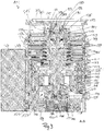
- turbomolecular pump 111 comprises a pump inlet 115 surrounded by an inlet flange 113, to which in a conventional manner, a non-illustrated recipient can be connected.
- the gas from the recipient may be drawn from the recipient via the pump inlet 115 and conveyed through the pump to a pump outlet 117 to which a backing pump, such as a rotary vane pump, may be connected.
- the inlet flange 113 forms according to the orientation of the vacuum pump Fig. 1 the upper end of the housing 119 of the vacuum pump 111.
- the housing 119 comprises a lower part 121, on which an electronics housing 123 is arranged laterally.
- Housed in the electronics housing 123 are electrical and / or electronic components of the vacuum pump 111, eg for operating an electric motor 125 arranged in the vacuum pump.
- a plurality of connections 127 for accessories are provided on the electronics housing 123.
- a data interface 129 for example, according to the RS485 standard, and a power supply terminal 131 on the electronics housing 123 are arranged.
- a flood inlet 133 in particular in the form of a flood valve, is provided, via which the vacuum pump 111 can be flooded.
- a sealing gas connection 135, which is also referred to as purge gas connection arranged, via which purge gas can be brought to protect the electric motor 125 from the pumped by the pump gas into the engine compartment 137, in which the electric motor 125 is housed in the vacuum pump 111.
- two coolant connections 139 are further arranged, wherein one of the coolant connections is provided as an inlet and the other coolant connection as an outlet for coolant, which can be passed for cooling purposes in the vacuum pump.
- the lower side 141 of the vacuum pump can serve as a base, so that the vacuum pump 111 can be operated standing on the bottom 141.
- the vacuum pump 111 can also be fastened to a recipient via the inlet flange 113 and thus be operated to a certain extent suspended.
- the vacuum pump 111 can be designed so that it can also be put into operation, if it is aligned differently than in Fig. 1 is shown.
- Embodiments of the vacuum pump can also be implemented in which the lower side 141 can not be turned down but can be turned to the side or directed upwards.
- a bearing cap 145 is attached to the bottom 141.
- mounting holes 147 are arranged, via which the pump 111 can be attached, for example, to a support surface.
- a coolant line 148 is shown, in which the coolant introduced and discharged via the coolant connections 139 can circulate.
- the vacuum pump comprises a plurality of process gas pumping stages for conveying the process gas pending at the pump inlet 115 to the pump outlet 117.
- a rotor 149 is arranged, which has a about a rotation axis 151 rotatable rotor shaft 153.
- Turbomolecular pump 111 includes a plurality of turbomolecular pump stages operatively connected in series with a plurality of rotor disks 155 mounted on rotor shaft 153 and stator disks 157 disposed between rotor disks 155 and housed in housing 119.
- a rotor disk 155 and an adjacent stator disk 157 each form a turbomolecular one pumping stage.
- the stator disks 157 are held by spacer rings 159 at a desired axial distance from each other.
- the vacuum pump further comprises Holweck pumping stages which are arranged one inside the other in the radial direction and which are pumpingly connected to one another in series.
- the rotor of the Holweck pump stages comprises a rotor hub 161 arranged on the rotor shaft 153 and two cylinder shell-shaped Holweck rotor sleeves 163, 165 fastened to the rotor hub 161 and oriented coaxially with the rotation axis 151 and nested in the radial direction.
- two cylinder jacket-shaped Holweck stator sleeves 167, 169 are provided, which are also oriented coaxially to the rotation axis 151 and, as seen in the radial direction, are nested one inside the other.
- the pump-active surfaces of the Holweck pump stages are formed by the lateral surfaces, ie by the radial inner and / or outer surfaces, the Holweck rotor sleeves 163, 165 and the Holweck stator sleeves 167, 169.
- the radially inner surface of the outer Holweck stator sleeve 167 faces the radially outer surface of the outer Holweck rotor sleeve 163, forming a radial Holweck gap 171, and forms with it the first Holweck pump stage subsequent to the turbomolecular pumps.
- the radially inner surface of the outer Holweck rotor sleeve 163 faces the radially outer surface of the inner Holweck stator sleeve 169 forming a radial Holweck gap 173 and forms with this a second Holweck pumping stage.
- the radially inner surface of the inner Holweck stator sleeve 169 faces the radially outer surface of the inner Holweck rotor sleeve 165 to form a radial Holweck gap 175 and forms with this the third Holweck pumping stage.
- a radially extending channel may be provided, via which the radially outer Holweck gap 171 is connected to the middle Holweck gap 173.
- a radially extending channel may be provided, via which the middle Holweck gap 173 is connected to the radially inner Holweck gap 175.
- a connecting channel 179 to the outlet 117 may be provided at the lower end of the radially inner Holweck rotor sleeve 165.
- the above-mentioned pump-active surfaces of the Holweck stator sleeves 163, 165 each have a plurality of Holweck grooves running around the axis of rotation 151 in the axial direction, while the opposite lateral surfaces of the Holweck rotor sleeves 163, 165 are smooth and the gas for operating the Drive vacuum pump 111 in the Holweck grooves.
- a roller bearing 181 in the region of the pump outlet 117 and a permanent magnet bearing 183 in the region of the pump inlet 115 are provided.
- a conical spray nut 185 with an outer diameter increasing toward the rolling bearing 181 is provided on the rotor shaft 153.
- the spray nut 185 is in sliding contact with at least one scraper of a resource storage.
- the resource storage comprises a plurality of stackable absorbent discs 187 provided with a rolling bearing bearing means 181, e.g. with a lubricant, soaked.
- the operating medium is transferred by capillary action of the resource storage on the scraper on the rotating sprayer nut 185 and promoted in the direction of increasing outer diameter of the spray nut 185 to the roller bearing 181 through where the centrifugal force along the spray nut 185 eg fulfills a lubricating function.
- the rolling bearing 181 and the resource storage are enclosed by a trough-shaped insert 189 and the bearing cap 145 in the vacuum pump.
- the permanent magnet bearing 183 includes a rotor-side bearing half 191 and a stator-side bearing half 193, each comprising a ring stack of a plurality of stacked in the axial direction of permanent magnetic rings 195, 197 include.
- the ring magnets 195, 197 are opposed to each other to form a radial bearing gap 199, wherein the rotor-side ring magnets 195 are disposed radially outward and the stator-side ring magnets 197 radially inward.
- the magnetic field present in the bearing gap 199 causes magnetic repulsive forces between the ring magnets 195, 197, which cause a radial bearing of the rotor shaft 153.
- the rotor-side ring magnets 195 are supported by a carrier section 201 of the rotor shaft 153, which surrounds the ring magnets 195 radially on the outside.
- the stator-side ring magnets 197 are supported by a stator-side support portion 203 which extends through the ring magnets 197 and is suspended on radial struts 205 of the housing 119.
- Parallel to the axis of rotation 151, the rotor-side ring magnets 195 are fixed by a lid element 207 coupled to the carrier section 203.
- the stator-side ring magnets 197 are fixed parallel to the axis of rotation 151 in one direction by a fastening ring 209 connected to the carrier section 203 and a fastening ring 211 connected to the carrier section 203. Between the fastening ring 211 and the ring magnet 197, a plate spring 213 may also be provided.
- an emergency bearing 215 which runs empty in the normal operation of the vacuum pump 111 without contact and engages only with an excessive radial deflection of the rotor 149 relative to the stator to a radial stop for the rotor 149th to form, since a collision of the rotor-side structures with the stator-side structures is prevented.
- the safety bearing 215 is designed as an unlubricated rolling bearing and forms with the rotor 149 and / or the stator a radial gap, which causes the safety bearing 215 is disengaged in the normal pumping operation.
- the radial deflection at which the safety bearing 215 engages is dimensioned large enough so that the safety bearing 215 does not engage during normal operation of the vacuum pump, and at the same time small enough so that a collision of the rotor-side structures with the stator-side structures under all circumstances is prevented.
- the vacuum pump 111 includes the electric motor 125 for rotationally driving the rotor 149.
- the armature of the electric motor 125 is formed by the rotor 149 whose rotor shaft 153 extends through the motor stator 217.
- On the extending through the motor stator 217 through portion of the rotor shaft 153 may radially outside or embedded a permanent magnet assembly be arranged.
- a gap 219 is arranged, which comprises a radial motor gap, via which the motor stator 217 and the permanent magnet arrangement for the transmission of the drive torque can influence magnetically.
- the motor stator 217 is fixed in the housing within the motor space 137 provided for the electric motor 125.
- a sealing gas which is also referred to as purge gas, and which may be, for example, air or nitrogen, enter the engine compartment 137.
- the electric motor 125 can be provided with process gas, e.g. against corrosive fractions of the process gas.
- the engine compartment 137 may also be evacuated via the pump outlet 117, i. In the engine compartment 137, at least approximately, the vacuum pressure caused by the backing pump connected to the pump outlet 117 prevails.
- delimiting wall 221 Between the rotor hub 161 and a motor space 137 delimiting wall 221 may also be a so-called. And per se known labyrinth seal 223 may be provided, in particular to achieve a better seal of the engine compartment 217 against the Holweck pump stages located radially outside.
- the above-described vacuum pump 111 is part of the prior art.
- the vacuum pump 111 is a hybrid-mounted turbomolecular pump, that is to say that the rotor 149 is mounted by means of a combination of roller bearings 181, here on the outlet side, and magnetic bearing 183, here on the inlet side.
- the vacuum pump 111 can advantageously be further developed according to the invention, and vice versa, the other vacuum pumps and operating methods described herein can be advantageously further developed by individual or a combination of features of the vacuum pump 111.
- an actuator 250 is shown that is capable of providing a variable stiffness and / or damping effect for a rolling bearing of a vacuum pump.
- the actuator 250 includes an electroactive polymer that forms a movable body 252.
- the body 252 is crossed by parallel aligned electrodes 254 which are connected to a voltage source 256, which is driven by a control device, not shown.
- a voltage is set between the electrodes 254 by the voltage source 256
- the shape of the body 252 changes, in particular in the vertical direction with respect to the electrodes 254, ie in FIG Fig. 6 vertical.
- Fig. 7 is a part of a rolling bearing 260 of a vacuum pump according to the invention schematically illustrated.
- the rolling bearing 260 is formed as a ball bearing and includes a plurality of balls 262, an inner bearing ring and a cage (not shown) and an outer bearing ring 264, on which the balls 262 roll.
- a rotation axis of a rotor, not shown, is indicated by axis 265.
- the bearing ring 264 is held by a suspension to a base member 266.
- the suspension includes two axially disposed passive suspension members 268 and a radially disposed passive suspension member 270.
- an actuator 272 is arranged on the base member 266, which is adapted to change its shape by an electrical voltage, in such a way that the actuator 272 toward the bearing ring 264, in Fig. 7 in the horizontal direction, expands and this finally applied.
- the passive suspension elements 268 and 270 are not controllable, hence the term "passive". These suspension elements are chosen in terms of their stiffness and damping effect according to an optimal design. In principle, however, it is also conceivable to provide these or other suspension elements with their own actuators, for example electrically deformable polymers, eg in order to achieve even more precise control of the overall rigidity and / or damping effect.
- the actuator 272 thus does not touch the bearing ring 264 in the illustrated state and is advantageously controlled in such a way that it is put under tension to increase the rigidity and damping effect of the rolling bearing 260, thereby expanding the bearing ring 264 and thus imparting a different stiffness to the bearing ring 264 and damping effect, as in the condition without contact.
- two switching states are advantageously realized, which correspond to two different levels of stiffness or damping effect.
- the bearing ring 264 here represents the outer ring of the rolling bearing 260. In principle, however, it is also possible for example for an inner ring to be suspended and actuated accordingly. Also, the actuator 272 may be attached to the bearing ring 264 and selectively bias the base member 266. The or an actuator may, for example, also act axially and in particular replace or supplement one of the passive suspension elements 268. In principle, however, not only a strict separation between the axial and radial suspension, as shown, is conceivable, but also, for example, a suspension element and / or actuator at one corner of the bearing ring 264 or in other forms of the bearing ring 264 also in numerous other places.
- Electrodes of the actuator 272 are indicated by parallel lines.
- an extension of the actuator 272 in a direction parallel to the electrodes is used.
- the rolling bearing 273 of the Fig. 8 differs essentially in that an actuator 274 is provided, whose extension is exploited in a direction perpendicular to the electrodes to act on the bearing ring 264.
- an actuator 276 is provided, which is permanently connected to both the base member 266 and the bearing ring 264.
- the actuator 276 provides the suspension of the bearing ring 264 a radial stiffness and damping effect even in the non-driven state by its passive material properties.
- suspension element 270 is provided by suspension element 270, omitted.
- the actuator 276 can be controlled in steps, for example, or continuously. Similar to the embodiment of the Fig. 7 Here, the change in shape of the actuator 276 is used in a direction parallel to the electrodes and perpendicular to the electric field, but also, for example, a use of the change in shape parallel to the electric field is conceivable.
- Fig. 10 a diagram is shown which shows plots of a vibration curve, determined as acceleration a of a surface of the vacuum pump, of a rotor as a function of its rotational frequency ⁇ .
- the rotor is part of an exemplary vacuum pump according to the invention, which is designed as a hybrid bearing turbomolecular pump. Shown are vibration curves at a lower part of the turbomolecular pump, ie in the vicinity of the rolling bearing.
- the rolling bearing of the turbomolecular pump is controlled such that two levels of stiffness and damping effect are realized, namely a "hard” and a "soft” setting with higher or lower stiffness and damping.
- a shrinkage curve 280 of the rotor which corresponds to a continuous soft setting of the rolling bearing.
- the rotor has two oscillation maxima in the shown rotational frequency range.
- a further waveform 282 is shown, which corresponds to a continuous hard setting of the rolling bearing, wherein the rotor in the illustrated rotational frequency range also has two oscillation maxima, but are at different rotational frequencies, as is the case for the soft setting.
- a waveform 284 is shown, which corresponds to the actual waveform in an advantageous control of the stiffness and the damping effect of the rolling bearing.
- the setting, ie hard or soft is always selected, which can expect a lower vibration amplitude for the existing speed or rotational frequency.
- the hard setting is selected.
- the first oscillation maximum of the soft setting is avoided.
- the soft setting is switched so that the first oscillation maximum of the hard setting is avoided.
- the respective second oscillation maximums are traversed, switching in each case at the intersections of the oscillation profiles 280 and 282 at a second switching frequency 288 and at a third switching frequency 290.
- the actual oscillation profile 284 is significantly lower overall in terms of its amplitude and in particular does not have the violent, resonance-caused maxima of the respective settings hard or soft.
- the sound emission of the pump which is significantly influenced by the applied surface acceleration, can be significantly reduced. This also has a positive effect on the service life of the pump.
- Fig. 11 is another graph with plotted waveforms, the control of stiffness and damping effect as regards Fig. 10 described underlying.
- the waveform 292 corresponds to the soft setting and the waveform 294 corresponds to the hard setting.
- the actual waveform 296 is indicated by a thicker line.
- the lowest possible vibration amplitude is used by the actual waveform 296 here. This is because the system has a slightly different vibration behavior in this other axial region.
- the chosen Umschaltstrategie between the soft and hard setting here the maximum vibration avoided and overall a relatively low amplitude vibration can be achieved.
- a switching or control strategy for the stiffness and / or the damping effect of the rolling bearing can also be designed differently, for example, be aligned to the vibration behavior at the level of the magentic bearing or a medium height, so that there each set the lowest possible vibration.
- a switching time ⁇ ⁇ 5 * 2 ⁇ / ⁇ between the two settings is particularly preferred, where ⁇ represents the rotational frequency of the rotor at the switching point.
- ⁇ represents the rotational frequency of the rotor at the switching point.
- switching times of at most 100 ms are advantageous.
- a merely gradual change On the other hand, it could lead to a steady-state rotor-dynamic state during the switching and thus to a short-term resonance peak.
- the vibrations in the vacuum pump can be significantly reduced by simple means and, in particular, violent oscillation maxima due to resonance can be avoided.
- a good smoothness with low acoustic emissions can be achieved.
- This not only makes the subjective acoustic perception of the pump more pleasant, but connected systems are also exposed to significantly lower vibrations, which can increase their working precision.
- the invention also has a positive effect on the life of the vacuum pump.
Landscapes
- Engineering & Computer Science (AREA)
- General Engineering & Computer Science (AREA)
- Mechanical Engineering (AREA)
- Physics & Mathematics (AREA)
- Acoustics & Sound (AREA)
- Aviation & Aerospace Engineering (AREA)
- Non-Positive Displacement Air Blowers (AREA)
Priority Applications (2)
| Application Number | Priority Date | Filing Date | Title |
|---|---|---|---|
| EP18159918.4A EP3536965B1 (fr) | 2018-03-05 | 2018-03-05 | Pompe à vide dans laquelle le support d'un palier à roulement a une rigidité et/ou un amortissement réglable(s) |
| JP2019029323A JP7208817B2 (ja) | 2018-03-05 | 2019-02-21 | 真空ポンプ、および真空ポンプの作動のための方法 |
Applications Claiming Priority (1)
| Application Number | Priority Date | Filing Date | Title |
|---|---|---|---|
| EP18159918.4A EP3536965B1 (fr) | 2018-03-05 | 2018-03-05 | Pompe à vide dans laquelle le support d'un palier à roulement a une rigidité et/ou un amortissement réglable(s) |
Publications (2)
| Publication Number | Publication Date |
|---|---|
| EP3536965A1 true EP3536965A1 (fr) | 2019-09-11 |
| EP3536965B1 EP3536965B1 (fr) | 2021-09-22 |
Family
ID=61563275
Family Applications (1)
| Application Number | Title | Priority Date | Filing Date |
|---|---|---|---|
| EP18159918.4A Active EP3536965B1 (fr) | 2018-03-05 | 2018-03-05 | Pompe à vide dans laquelle le support d'un palier à roulement a une rigidité et/ou un amortissement réglable(s) |
Country Status (2)
| Country | Link |
|---|---|
| EP (1) | EP3536965B1 (fr) |
| JP (1) | JP7208817B2 (fr) |
Cited By (1)
| Publication number | Priority date | Publication date | Assignee | Title |
|---|---|---|---|---|
| WO2024256055A1 (fr) * | 2023-06-15 | 2024-12-19 | Pfeiffer Vacuum | Pompe à vide turbomoléculaire |
Families Citing this family (1)
| Publication number | Priority date | Publication date | Assignee | Title |
|---|---|---|---|---|
| EP3808988B1 (fr) * | 2020-03-27 | 2024-01-10 | Pfeiffer Vacuum Technology AG | Pompe à vide et procédé de surveillance d'une pompe à vide |
Citations (9)
| Publication number | Priority date | Publication date | Assignee | Title |
|---|---|---|---|---|
| DE2519651A1 (de) * | 1975-05-02 | 1976-11-11 | Teldix Gmbh | Magnetische anordnung |
| JPH03213695A (ja) * | 1990-01-17 | 1991-09-19 | Hitachi Ltd | ターボ形真空ポンプ |
| DE102007052479A1 (de) * | 2007-11-02 | 2009-05-07 | Oerlikon Leybold Vacuum Gmbh | Pumpen-Lageranordnung |
| DE102011005494A1 (de) * | 2011-03-14 | 2012-09-20 | Aktiebolaget Skf | Lageranordnung |
| EP2884125A2 (fr) * | 2013-12-13 | 2015-06-17 | Pfeiffer Vacuum Gmbh | Système rotatif |
| CN105508498A (zh) * | 2015-12-19 | 2016-04-20 | 东北大学 | 一种抑制旋转机械转子振动的方法 |
| EP3043074A1 (fr) * | 2015-01-06 | 2016-07-13 | Pfeiffer Vacuum GmbH | Système de pallier d'arbre de pompe à vide |
| WO2019008370A1 (fr) * | 2017-07-07 | 2019-01-10 | Edwards Limited | Amortisseur magnétorhéologique et procédé d'amortissement |
| EP3444478A1 (fr) * | 2017-08-18 | 2019-02-20 | Pfeiffer Vacuum Gmbh | Pompe à vide |
Family Cites Families (2)
| Publication number | Priority date | Publication date | Assignee | Title |
|---|---|---|---|---|
| JPH01294995A (ja) * | 1988-05-20 | 1989-11-28 | Hitachi Ltd | 真空ポンプ |
| JPH07135345A (ja) * | 1993-11-09 | 1995-05-23 | Casio Comput Co Ltd | 圧電素子 |
-
2018
- 2018-03-05 EP EP18159918.4A patent/EP3536965B1/fr active Active
-
2019
- 2019-02-21 JP JP2019029323A patent/JP7208817B2/ja active Active
Patent Citations (9)
| Publication number | Priority date | Publication date | Assignee | Title |
|---|---|---|---|---|
| DE2519651A1 (de) * | 1975-05-02 | 1976-11-11 | Teldix Gmbh | Magnetische anordnung |
| JPH03213695A (ja) * | 1990-01-17 | 1991-09-19 | Hitachi Ltd | ターボ形真空ポンプ |
| DE102007052479A1 (de) * | 2007-11-02 | 2009-05-07 | Oerlikon Leybold Vacuum Gmbh | Pumpen-Lageranordnung |
| DE102011005494A1 (de) * | 2011-03-14 | 2012-09-20 | Aktiebolaget Skf | Lageranordnung |
| EP2884125A2 (fr) * | 2013-12-13 | 2015-06-17 | Pfeiffer Vacuum Gmbh | Système rotatif |
| EP3043074A1 (fr) * | 2015-01-06 | 2016-07-13 | Pfeiffer Vacuum GmbH | Système de pallier d'arbre de pompe à vide |
| CN105508498A (zh) * | 2015-12-19 | 2016-04-20 | 东北大学 | 一种抑制旋转机械转子振动的方法 |
| WO2019008370A1 (fr) * | 2017-07-07 | 2019-01-10 | Edwards Limited | Amortisseur magnétorhéologique et procédé d'amortissement |
| EP3444478A1 (fr) * | 2017-08-18 | 2019-02-20 | Pfeiffer Vacuum Gmbh | Pompe à vide |
Cited By (2)
| Publication number | Priority date | Publication date | Assignee | Title |
|---|---|---|---|---|
| WO2024256055A1 (fr) * | 2023-06-15 | 2024-12-19 | Pfeiffer Vacuum | Pompe à vide turbomoléculaire |
| FR3149936A1 (fr) * | 2023-06-15 | 2024-12-20 | Pfeiffer Vacuum | Pompe à vide turbomoléculaire |
Also Published As
| Publication number | Publication date |
|---|---|
| EP3536965B1 (fr) | 2021-09-22 |
| JP2019163764A (ja) | 2019-09-26 |
| JP7208817B2 (ja) | 2023-01-19 |
Similar Documents
| Publication | Publication Date | Title |
|---|---|---|
| EP3657021B1 (fr) | Pompe à vide | |
| EP3444478B1 (fr) | Pompe à vide | |
| EP3536965B1 (fr) | Pompe à vide dans laquelle le support d'un palier à roulement a une rigidité et/ou un amortissement réglable(s) | |
| EP3385961B1 (fr) | Aimant permanent monolithique | |
| EP3926175B1 (fr) | Pompe à vide dotée d'un palier à roulement | |
| EP3135932B1 (fr) | Pompe à vide et palier à aimant permanent | |
| EP3683449B1 (fr) | Palier magnétique et appareil sous vide | |
| EP4144994B1 (fr) | Dispositif et procédé d'évaluation d'un palier magnétique | |
| EP4194700B1 (fr) | Pompe à vide avec étage de pompe de holweck à géométrie de holweck variable | |
| EP3653884B1 (fr) | Pompe à vide | |
| EP3473858B1 (fr) | Procédé d'optimisation de durée de vie des paliers à rouleaux d'une pompe à vide | |
| EP3196471B1 (fr) | Pompe a vide | |
| EP3633204B1 (fr) | Pompe à vide | |
| EP3327293B1 (fr) | Pompe à vide avec une pluralté d'entrées | |
| EP3708843B1 (fr) | Procédé de fabrication d'un moteur électrique ou d'un appareil a vide avec un tel moteur | |
| EP3650702B1 (fr) | Utilisation d'une huile synthétique dans une pompe à vide et pompe à vide | |
| EP3907406A1 (fr) | Pompe à vide | |
| EP4273405B1 (fr) | Pompe à vide avec un étage de pompage de type holweck avec une géométrie holweck variable | |
| EP4474654B1 (fr) | Pompe à vide turbomoléculaire | |
| EP3561307A1 (fr) | Pompe à vide avec une bride de port d'aspiration et un support de palier dans le port d'aspiration | |
| EP3926174B1 (fr) | Pompe à vide | |
| EP3628883B1 (fr) | Pompe à vide | |
| EP4174321B1 (fr) | Pompe à vide | |
| EP3767109B1 (fr) | Système à vide | |
| EP3499044B1 (fr) | Pompe à vide |
Legal Events
| Date | Code | Title | Description |
|---|---|---|---|
| PUAI | Public reference made under article 153(3) epc to a published international application that has entered the european phase |
Free format text: ORIGINAL CODE: 0009012 |
|
| STAA | Information on the status of an ep patent application or granted ep patent |
Free format text: STATUS: THE APPLICATION HAS BEEN PUBLISHED |
|
| AK | Designated contracting states |
Kind code of ref document: A1 Designated state(s): AL AT BE BG CH CY CZ DE DK EE ES FI FR GB GR HR HU IE IS IT LI LT LU LV MC MK MT NL NO PL PT RO RS SE SI SK SM TR |
|
| AX | Request for extension of the european patent |
Extension state: BA ME |
|
| STAA | Information on the status of an ep patent application or granted ep patent |
Free format text: STATUS: REQUEST FOR EXAMINATION WAS MADE |
|
| STAA | Information on the status of an ep patent application or granted ep patent |
Free format text: STATUS: EXAMINATION IS IN PROGRESS |
|
| 17P | Request for examination filed |
Effective date: 20200310 |
|
| RBV | Designated contracting states (corrected) |
Designated state(s): AL AT BE BG CH CY CZ DE DK EE ES FI FR GB GR HR HU IE IS IT LI LT LU LV MC MK MT NL NO PL PT RO RS SE SI SK SM TR |
|
| 17Q | First examination report despatched |
Effective date: 20200330 |
|
| GRAP | Despatch of communication of intention to grant a patent |
Free format text: ORIGINAL CODE: EPIDOSNIGR1 |
|
| STAA | Information on the status of an ep patent application or granted ep patent |
Free format text: STATUS: GRANT OF PATENT IS INTENDED |
|
| INTG | Intention to grant announced |
Effective date: 20210531 |
|
| GRAS | Grant fee paid |
Free format text: ORIGINAL CODE: EPIDOSNIGR3 |
|
| GRAA | (expected) grant |
Free format text: ORIGINAL CODE: 0009210 |
|
| STAA | Information on the status of an ep patent application or granted ep patent |
Free format text: STATUS: THE PATENT HAS BEEN GRANTED |
|
| AK | Designated contracting states |
Kind code of ref document: B1 Designated state(s): AL AT BE BG CH CY CZ DE DK EE ES FI FR GB GR HR HU IE IS IT LI LT LU LV MC MK MT NL NO PL PT RO RS SE SI SK SM TR |
|
| REG | Reference to a national code |
Ref country code: GB Ref legal event code: FG4D Free format text: NOT ENGLISH |
|
| REG | Reference to a national code |
Ref country code: DE Ref legal event code: R096 Ref document number: 502018007135 Country of ref document: DE |
|
| REG | Reference to a national code |
Ref country code: IE Ref legal event code: FG4D Free format text: LANGUAGE OF EP DOCUMENT: GERMAN |
|
| REG | Reference to a national code |
Ref country code: CH Ref legal event code: EP Ref country code: AT Ref legal event code: REF Ref document number: 1432541 Country of ref document: AT Kind code of ref document: T Effective date: 20211015 |
|
| REG | Reference to a national code |
Ref country code: LT Ref legal event code: MG9D |
|
| REG | Reference to a national code |
Ref country code: NL Ref legal event code: MP Effective date: 20210922 |
|
| PG25 | Lapsed in a contracting state [announced via postgrant information from national office to epo] |
Ref country code: SE Free format text: LAPSE BECAUSE OF FAILURE TO SUBMIT A TRANSLATION OF THE DESCRIPTION OR TO PAY THE FEE WITHIN THE PRESCRIBED TIME-LIMIT Effective date: 20210922 Ref country code: RS Free format text: LAPSE BECAUSE OF FAILURE TO SUBMIT A TRANSLATION OF THE DESCRIPTION OR TO PAY THE FEE WITHIN THE PRESCRIBED TIME-LIMIT Effective date: 20210922 Ref country code: FI Free format text: LAPSE BECAUSE OF FAILURE TO SUBMIT A TRANSLATION OF THE DESCRIPTION OR TO PAY THE FEE WITHIN THE PRESCRIBED TIME-LIMIT Effective date: 20210922 Ref country code: HR Free format text: LAPSE BECAUSE OF FAILURE TO SUBMIT A TRANSLATION OF THE DESCRIPTION OR TO PAY THE FEE WITHIN THE PRESCRIBED TIME-LIMIT Effective date: 20210922 Ref country code: NO Free format text: LAPSE BECAUSE OF FAILURE TO SUBMIT A TRANSLATION OF THE DESCRIPTION OR TO PAY THE FEE WITHIN THE PRESCRIBED TIME-LIMIT Effective date: 20211222 Ref country code: LT Free format text: LAPSE BECAUSE OF FAILURE TO SUBMIT A TRANSLATION OF THE DESCRIPTION OR TO PAY THE FEE WITHIN THE PRESCRIBED TIME-LIMIT Effective date: 20210922 Ref country code: BG Free format text: LAPSE BECAUSE OF FAILURE TO SUBMIT A TRANSLATION OF THE DESCRIPTION OR TO PAY THE FEE WITHIN THE PRESCRIBED TIME-LIMIT Effective date: 20211222 |
|
| PG25 | Lapsed in a contracting state [announced via postgrant information from national office to epo] |
Ref country code: LV Free format text: LAPSE BECAUSE OF FAILURE TO SUBMIT A TRANSLATION OF THE DESCRIPTION OR TO PAY THE FEE WITHIN THE PRESCRIBED TIME-LIMIT Effective date: 20210922 Ref country code: GR Free format text: LAPSE BECAUSE OF FAILURE TO SUBMIT A TRANSLATION OF THE DESCRIPTION OR TO PAY THE FEE WITHIN THE PRESCRIBED TIME-LIMIT Effective date: 20211223 |
|
| PG25 | Lapsed in a contracting state [announced via postgrant information from national office to epo] |
Ref country code: IS Free format text: LAPSE BECAUSE OF FAILURE TO SUBMIT A TRANSLATION OF THE DESCRIPTION OR TO PAY THE FEE WITHIN THE PRESCRIBED TIME-LIMIT Effective date: 20220122 Ref country code: SK Free format text: LAPSE BECAUSE OF FAILURE TO SUBMIT A TRANSLATION OF THE DESCRIPTION OR TO PAY THE FEE WITHIN THE PRESCRIBED TIME-LIMIT Effective date: 20210922 Ref country code: RO Free format text: LAPSE BECAUSE OF FAILURE TO SUBMIT A TRANSLATION OF THE DESCRIPTION OR TO PAY THE FEE WITHIN THE PRESCRIBED TIME-LIMIT Effective date: 20210922 Ref country code: PT Free format text: LAPSE BECAUSE OF FAILURE TO SUBMIT A TRANSLATION OF THE DESCRIPTION OR TO PAY THE FEE WITHIN THE PRESCRIBED TIME-LIMIT Effective date: 20220124 Ref country code: PL Free format text: LAPSE BECAUSE OF FAILURE TO SUBMIT A TRANSLATION OF THE DESCRIPTION OR TO PAY THE FEE WITHIN THE PRESCRIBED TIME-LIMIT Effective date: 20210922 Ref country code: NL Free format text: LAPSE BECAUSE OF FAILURE TO SUBMIT A TRANSLATION OF THE DESCRIPTION OR TO PAY THE FEE WITHIN THE PRESCRIBED TIME-LIMIT Effective date: 20210922 Ref country code: ES Free format text: LAPSE BECAUSE OF FAILURE TO SUBMIT A TRANSLATION OF THE DESCRIPTION OR TO PAY THE FEE WITHIN THE PRESCRIBED TIME-LIMIT Effective date: 20210922 Ref country code: EE Free format text: LAPSE BECAUSE OF FAILURE TO SUBMIT A TRANSLATION OF THE DESCRIPTION OR TO PAY THE FEE WITHIN THE PRESCRIBED TIME-LIMIT Effective date: 20210922 Ref country code: AL Free format text: LAPSE BECAUSE OF FAILURE TO SUBMIT A TRANSLATION OF THE DESCRIPTION OR TO PAY THE FEE WITHIN THE PRESCRIBED TIME-LIMIT Effective date: 20210922 |
|
| REG | Reference to a national code |
Ref country code: DE Ref legal event code: R097 Ref document number: 502018007135 Country of ref document: DE |
|
| PG25 | Lapsed in a contracting state [announced via postgrant information from national office to epo] |
Ref country code: DK Free format text: LAPSE BECAUSE OF FAILURE TO SUBMIT A TRANSLATION OF THE DESCRIPTION OR TO PAY THE FEE WITHIN THE PRESCRIBED TIME-LIMIT Effective date: 20210922 |
|
| PLBE | No opposition filed within time limit |
Free format text: ORIGINAL CODE: 0009261 |
|
| STAA | Information on the status of an ep patent application or granted ep patent |
Free format text: STATUS: NO OPPOSITION FILED WITHIN TIME LIMIT |
|
| 26N | No opposition filed |
Effective date: 20220623 |
|
| PG25 | Lapsed in a contracting state [announced via postgrant information from national office to epo] |
Ref country code: MC Free format text: LAPSE BECAUSE OF FAILURE TO SUBMIT A TRANSLATION OF THE DESCRIPTION OR TO PAY THE FEE WITHIN THE PRESCRIBED TIME-LIMIT Effective date: 20210922 |
|
| REG | Reference to a national code |
Ref country code: CH Ref legal event code: PL |
|
| PG25 | Lapsed in a contracting state [announced via postgrant information from national office to epo] |
Ref country code: SI Free format text: LAPSE BECAUSE OF FAILURE TO SUBMIT A TRANSLATION OF THE DESCRIPTION OR TO PAY THE FEE WITHIN THE PRESCRIBED TIME-LIMIT Effective date: 20210922 |
|
| REG | Reference to a national code |
Ref country code: BE Ref legal event code: MM Effective date: 20220331 |
|
| PG25 | Lapsed in a contracting state [announced via postgrant information from national office to epo] |
Ref country code: LU Free format text: LAPSE BECAUSE OF NON-PAYMENT OF DUE FEES Effective date: 20220305 Ref country code: LI Free format text: LAPSE BECAUSE OF NON-PAYMENT OF DUE FEES Effective date: 20220331 Ref country code: IE Free format text: LAPSE BECAUSE OF NON-PAYMENT OF DUE FEES Effective date: 20220305 Ref country code: FR Free format text: LAPSE BECAUSE OF NON-PAYMENT OF DUE FEES Effective date: 20220331 Ref country code: CH Free format text: LAPSE BECAUSE OF NON-PAYMENT OF DUE FEES Effective date: 20220331 |
|
| PG25 | Lapsed in a contracting state [announced via postgrant information from national office to epo] |
Ref country code: BE Free format text: LAPSE BECAUSE OF NON-PAYMENT OF DUE FEES Effective date: 20220331 |
|
| PG25 | Lapsed in a contracting state [announced via postgrant information from national office to epo] |
Ref country code: SM Free format text: LAPSE BECAUSE OF FAILURE TO SUBMIT A TRANSLATION OF THE DESCRIPTION OR TO PAY THE FEE WITHIN THE PRESCRIBED TIME-LIMIT Effective date: 20210922 Ref country code: MK Free format text: LAPSE BECAUSE OF FAILURE TO SUBMIT A TRANSLATION OF THE DESCRIPTION OR TO PAY THE FEE WITHIN THE PRESCRIBED TIME-LIMIT Effective date: 20210922 Ref country code: CY Free format text: LAPSE BECAUSE OF FAILURE TO SUBMIT A TRANSLATION OF THE DESCRIPTION OR TO PAY THE FEE WITHIN THE PRESCRIBED TIME-LIMIT Effective date: 20210922 |
|
| REG | Reference to a national code |
Ref country code: AT Ref legal event code: MM01 Ref document number: 1432541 Country of ref document: AT Kind code of ref document: T Effective date: 20230305 |
|
| PG25 | Lapsed in a contracting state [announced via postgrant information from national office to epo] |
Ref country code: HU Free format text: LAPSE BECAUSE OF FAILURE TO SUBMIT A TRANSLATION OF THE DESCRIPTION OR TO PAY THE FEE WITHIN THE PRESCRIBED TIME-LIMIT; INVALID AB INITIO Effective date: 20180305 |
|
| PG25 | Lapsed in a contracting state [announced via postgrant information from national office to epo] |
Ref country code: AT Free format text: LAPSE BECAUSE OF NON-PAYMENT OF DUE FEES Effective date: 20230305 |
|
| PG25 | Lapsed in a contracting state [announced via postgrant information from national office to epo] |
Ref country code: AT Free format text: LAPSE BECAUSE OF NON-PAYMENT OF DUE FEES Effective date: 20230305 |
|
| PG25 | Lapsed in a contracting state [announced via postgrant information from national office to epo] |
Ref country code: MT Free format text: LAPSE BECAUSE OF FAILURE TO SUBMIT A TRANSLATION OF THE DESCRIPTION OR TO PAY THE FEE WITHIN THE PRESCRIBED TIME-LIMIT Effective date: 20210922 |
|
| PGFP | Annual fee paid to national office [announced via postgrant information from national office to epo] |
Ref country code: DE Payment date: 20250527 Year of fee payment: 8 |
|
| PG25 | Lapsed in a contracting state [announced via postgrant information from national office to epo] |
Ref country code: TR Free format text: LAPSE BECAUSE OF FAILURE TO SUBMIT A TRANSLATION OF THE DESCRIPTION OR TO PAY THE FEE WITHIN THE PRESCRIBED TIME-LIMIT Effective date: 20210922 |
|
| PGFP | Annual fee paid to national office [announced via postgrant information from national office to epo] |
Ref country code: GB Payment date: 20260324 Year of fee payment: 9 |
|
| PGFP | Annual fee paid to national office [announced via postgrant information from national office to epo] |
Ref country code: AT Payment date: 20260410 Year of fee payment: 5 |
|
| PGFP | Annual fee paid to national office [announced via postgrant information from national office to epo] |
Ref country code: IT Payment date: 20260324 Year of fee payment: 9 |
|
| PGFP | Annual fee paid to national office [announced via postgrant information from national office to epo] |
Ref country code: CZ Payment date: 20260225 Year of fee payment: 9 |