EP4273405B1 - Pompe à vide avec un étage de pompage de type holweck avec une géométrie holweck variable - Google Patents
Pompe à vide avec un étage de pompage de type holweck avec une géométrie holweck variable Download PDFInfo
- Publication number
- EP4273405B1 EP4273405B1 EP23198541.7A EP23198541A EP4273405B1 EP 4273405 B1 EP4273405 B1 EP 4273405B1 EP 23198541 A EP23198541 A EP 23198541A EP 4273405 B1 EP4273405 B1 EP 4273405B1
- Authority
- EP
- European Patent Office
- Prior art keywords
- sleeve
- contour
- holweck
- sleeve section
- face
- Prior art date
- Legal status (The legal status is an assumption and is not a legal conclusion. Google has not performed a legal analysis and makes no representation as to the accuracy of the status listed.)
- Active
Links
Images


Classifications
-
- F—MECHANICAL ENGINEERING; LIGHTING; HEATING; WEAPONS; BLASTING
- F04—POSITIVE - DISPLACEMENT MACHINES FOR LIQUIDS; PUMPS FOR LIQUIDS OR ELASTIC FLUIDS
- F04D—NON-POSITIVE-DISPLACEMENT PUMPS
- F04D19/00—Axial-flow pumps
- F04D19/02—Multi-stage pumps
- F04D19/04—Multi-stage pumps specially adapted to the production of a high vacuum, e.g. molecular pumps
- F04D19/044—Holweck-type pumps
-
- F—MECHANICAL ENGINEERING; LIGHTING; HEATING; WEAPONS; BLASTING
- F04—POSITIVE - DISPLACEMENT MACHINES FOR LIQUIDS; PUMPS FOR LIQUIDS OR ELASTIC FLUIDS
- F04D—NON-POSITIVE-DISPLACEMENT PUMPS
- F04D29/00—Details, component parts, or accessories
- F04D29/40—Casings; Connections of working fluid
- F04D29/52—Casings; Connections of working fluid for axial pumps
- F04D29/54—Fluid-guiding means, e.g. diffusers
- F04D29/541—Specially adapted for elastic fluid pumps
- F04D29/542—Bladed diffusers
Definitions
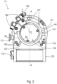
- the present invention relates to a vacuum pump, also referred to here only as a pump, in particular a turbomolecular vacuum pump, according to the preamble of claim 1 with an internal Holweck pumping stage.
- a generic vacuum pump is essentially based on the type of EP 2 933 497 A2
- a vacuum pump of essentially the same type is also known from the EP 4 212 730 A1 , although the inner or internal stator sleeve is not formed in several parts. Further prior art can also be found in the publications EP 2 594 803 A1 and WO 2011 / 070 856 A1 .
- Vacuum pumps are used in various fields of technology. Depending on the requirements, vacuum pumps can have one or more pumping stages. Holweck pumping stages generally belong to the class of molecular vacuum pumps and generate a molecular flow by rotating a Holweck rotor relative to a stationary Holweck stator. In principle, a vacuum pump can comprise one or more Holweck pumping stages, with several Holweck pumping stages being able to be operated both in series and in parallel. Holweck pumping stages are typically used in turbomolecular vacuum pumps, where they are arranged downstream of one or more turbomolecular pumping stages in the direction of flow.
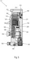
- a Holweck pump usually comprises a Holweck rotor and a Holweck stator, the Holweck rotor having a rotor shaft to which One or more Holweck rotor sleeves are provided concentrically in a, for example, disc-shaped Holweck hub.
- the Holweck hub and the Holweck rotor sleeve can be integral or one-piece; alternatively, the Holweck hub and the Holweck rotor sleeve can initially be separately manufactured parts that are subsequently joined together, for example by welding.
- a Holweck stator sleeve assigned to the respective Holweck rotor sleeves is provided with a single or multi-start Holweck thread and forms a Holweck gap with the respective Holweck rotor sleeve.
- the gas molecules to be conveyed are conveyed by the rotating movement of the Holweck rotor relative to the Holweck stator along the threads from an inlet to an outlet of the respective Holweck pump stage.
- a thread comprises a spiral-shaped Holweck channel in the form of a thread groove, delimited by the walls of a web, in which the gas molecules are conveyed when the rotor sleeve rotates relative to the stator sleeve.
- Holweck pumping stages are arranged concentrically to one another and nested within one another, so that the pumping direction of radially immediately successive Holweck pumping stages is opposite to one another.
- the radially outer rotor sleeve can, in turn, be surrounded by an outer stator sleeve to form, together with the outer rotor sleeve, another Holweck pumping stage.
- the stator sleeve located radially outside the outer rotor sleeve the stator sleeve located radially inside the outer rotor sleeve is consistently referred to in this context as also referred to as the inner stator sleeve, even if this may not itself surround an inner rotor sleeve.
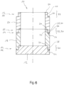
- the respective cylinder outer surface 40 can have a certain radial oversize relative to the respective cylinder inner surface 38 in order to be able to connect the sleeve sections 18, 20 to one another by means of a press-fit connection effective along the two cylinder surfaces 38, 40.
- it can be provided to form an internal thread on the respective cylinder inner surface 38 and an external thread matching the internal thread on the respective cylinder outer surface 40 in order to be able to screw the sleeve sections 18, 20 together.
Landscapes
- Engineering & Computer Science (AREA)
- Mechanical Engineering (AREA)
- General Engineering & Computer Science (AREA)
- Non-Positive Displacement Air Blowers (AREA)
Claims (6)
- Pompe à vide (111), en particulier pompe à vide turbomoléculaire (111), présentant au moins un étage de pompage Holweck qui comprend un stator Holweck et un rotor Holweck ;le stator Holweck comprenant un manchon de stator (10, 169) qui est réalisé en plusieurs parties et qui présente une extrémité fixe (14), montée sur une portion de carter stationnaire (12) de la pompe à vide (111), et une extrémité libre (16), opposée à l'extrémité fixe (14) dans la direction axiale ; le rotor Holweck comprenant un manchon de rotor (163) qui entoure le manchon de stator (10, 169) en formant un interstice Holweck (173) ; caractérisée en ce quele manchon de stator (10, 169) comprend une première portion de manchon (18) avec une première extrémité (22) et une deuxième extrémité (24) opposée à la première extrémité (22) et au moins une deuxième portion de manchon (20) avec une première extrémité (26) et une deuxième extrémité (28) opposée à la première extrémité (26), la première extrémité (22) de la première portion de manchon (18) étant fixée à la portion de carter stationnaire (12), et la première extrémité (26) de la deuxième portion de manchon (20) étant fixée à la deuxième extrémité (24) de la première portion de manchon (18) ;et caractérisée en outre en ce quela première extrémité (22) de la première portion de manchon (18) présente un premier contour frontal (30), et la première extrémité de la deuxième portion de manchon (20) présente un premier contour frontal (30) qui correspond au premier contour frontal (30) de la première portion de manchon (18) ; et/ou en ce quela deuxième extrémité (24) de la première portion de manchon (18) présente un deuxième contour frontal (32), et la deuxième extrémité (28) de la deuxième portion de manchon (20) présente un deuxième contour frontal (32) qui correspond au deuxième contour frontal (32) de la première portion de manchon (18).
- Pompe à vide (111) selon la revendication 1,
caractérisée en ce quela première extrémité (22) de la première portion de manchon (18) présente un premier contour frontal (30), et la deuxième extrémité de la deuxième portion de manchon (20) présente un deuxième contour frontal (32) qui est complémentaire au premier contour frontal (30) de la première portion de manchon (18) ; et/oula première extrémité (26) de la deuxième portion de manchon (20) présente un premier contour frontal (30), et la deuxième extrémité de la première portion de manchon (18) présente un deuxième contour frontal (32) qui est formé complémentaire au premier contour frontal (30) de la deuxième portion de manchon (20). - Pompe à vide (111) selon la revendication 1 ou 2,
caractérisée en ce quele premier contour frontal respectif (30) présente une première surface frontale (34) et une deuxième surface frontale (36) qui est en retrait par rapport à la première surface frontale (34) dans la direction axiale ; et/oule deuxième contour frontal respectif (32) présente une première surface frontale (34) et une deuxième surface frontale (36) qui est en retrait par rapport à la première surface frontale (34) dans la direction axiale. - Pompe à vide (111) selon la revendication 3,
caractérisée en ce que
la distance entre la première surface frontale (34) du premier contour frontal (30) et la deuxième surface frontale (36) du deuxième contour frontal (32) correspond à la distance entre la deuxième surface frontale (36) du premier contour frontal (30) et la première surface frontale (34) du deuxième contour frontal (32). - Pompe à vide (111) selon la revendication 3 ou 4,
caractérisée en ce que
la première surface frontale (34) du premier contour frontal (30) est reliée à la deuxième surface frontale (36) du premier contour frontal (30) par une surface intérieure de cylindre (38), et la première surface frontale (34) du deuxième contour frontal (32) est reliée à la deuxième surface frontale (36) du deuxième contour frontal (32) par une surface extérieure de cylindre (40) qui présente un diamètre plus grand que la surface intérieure de cylindre (38) du premier contour frontal (30). - Pompe à vide (111) selon l'une des revendications précédentes,
caractérisée en ce que
un filetage est réalisé sur le manchon de stator (10, 169), qui présente plusieurs rainures de filetage délimitées par des nervures formées sur le manchon de stator (10, 169) et par un fond de rainure formé par le manchon de stator (10, 169), sachant que le filetage de la première portion de manchon (18) diffère du filetage de la deuxième portion de manchon (20) par au moins un paramètre de filetage, ledit au moins un paramètre de filetage étant choisi dans le groupe de paramètres de filetage constitué par le nombre de nervures, le pas de filetage, la largeur des rainures de filetage, la largeur des nervures et la hauteur des nervures au-dessus du fond de rainure.
Priority Applications (2)
| Application Number | Priority Date | Filing Date | Title |
|---|---|---|---|
| EP23198541.7A EP4273405B1 (fr) | 2023-09-20 | 2023-09-20 | Pompe à vide avec un étage de pompage de type holweck avec une géométrie holweck variable |
| JP2023213953A JP2025048693A (ja) | 2023-09-20 | 2023-12-19 | モジュール式に構成されたホルベックポンプ段を有する真空ポンプ |
Applications Claiming Priority (1)
| Application Number | Priority Date | Filing Date | Title |
|---|---|---|---|
| EP23198541.7A EP4273405B1 (fr) | 2023-09-20 | 2023-09-20 | Pompe à vide avec un étage de pompage de type holweck avec une géométrie holweck variable |
Publications (3)
| Publication Number | Publication Date |
|---|---|
| EP4273405A1 EP4273405A1 (fr) | 2023-11-08 |
| EP4273405B1 true EP4273405B1 (fr) | 2025-07-09 |
| EP4273405C0 EP4273405C0 (fr) | 2025-07-09 |
Family
ID=88098157
Family Applications (1)
| Application Number | Title | Priority Date | Filing Date |
|---|---|---|---|
| EP23198541.7A Active EP4273405B1 (fr) | 2023-09-20 | 2023-09-20 | Pompe à vide avec un étage de pompage de type holweck avec une géométrie holweck variable |
Country Status (2)
| Country | Link |
|---|---|
| EP (1) | EP4273405B1 (fr) |
| JP (1) | JP2025048693A (fr) |
Family Cites Families (6)
| Publication number | Priority date | Publication date | Assignee | Title |
|---|---|---|---|---|
| KR101773632B1 (ko) * | 2009-12-11 | 2017-08-31 | 에드워즈 가부시키가이샤 | 나사 홈 배기부의 통형 고정 부재와 이것을 사용한 진공 펌프 |
| DE102011118661A1 (de) * | 2011-11-16 | 2013-05-16 | Pfeiffer Vacuum Gmbh | Reibungsvakuumpumpe |
| DE202013008470U1 (de) * | 2013-09-24 | 2015-01-08 | Oerlikon Leybold Vacuum Gmbh | Vakuumpumpe |
| DE102014105582A1 (de) * | 2014-04-17 | 2015-10-22 | Pfeiffer Vacuum Gmbh | Vakuumpumpe |
| EP3916235B1 (fr) * | 2020-05-27 | 2023-04-26 | Pfeiffer Vacuum Technology AG | Procédé de fabrication d'une pompe à vide |
| EP4212730A1 (fr) * | 2023-01-31 | 2023-07-19 | Pfeiffer Vacuum Technology AG | Pompe à vide avec étage de pompage de holward optimisé pour compenser la perte de performance liée à la température |
-
2023
- 2023-09-20 EP EP23198541.7A patent/EP4273405B1/fr active Active
- 2023-12-19 JP JP2023213953A patent/JP2025048693A/ja active Pending
Also Published As
| Publication number | Publication date |
|---|---|
| JP2025048693A (ja) | 2025-04-03 |
| EP4273405A1 (fr) | 2023-11-08 |
| EP4273405C0 (fr) | 2025-07-09 |
Similar Documents
| Publication | Publication Date | Title |
|---|---|---|
| EP3657021B1 (fr) | Pompe à vide | |
| EP2829734A1 (fr) | Pompe à vide | |
| EP4108932B1 (fr) | Reciate et système avec reciate et pompe à vide élevé | |
| EP3845764B1 (fr) | Pompe à vide et système de pompe à vide | |
| EP3670924B1 (fr) | Pompe à vide et procédé de fabrication d'une telle pompe à vide | |
| EP3926175B1 (fr) | Pompe à vide dotée d'un palier à roulement | |
| EP4194700B1 (fr) | Pompe à vide avec étage de pompe de holweck à géométrie de holweck variable | |
| EP4273405B1 (fr) | Pompe à vide avec un étage de pompage de type holweck avec une géométrie holweck variable | |
| EP3135932B1 (fr) | Pompe à vide et palier à aimant permanent | |
| EP3907406B1 (fr) | Pompe à vide | |
| EP3196471B1 (fr) | Pompe a vide | |
| EP3734078B1 (fr) | Pompe turbomoléculaire et procédé de fabrication d'un disque de stator pour une telle pompe | |
| EP4212730A1 (fr) | Pompe à vide avec étage de pompage de holward optimisé pour compenser la perte de performance liée à la température | |
| EP3760872B1 (fr) | Pompe à vide pourvue d'un agencement de fixation destiné à l'application de la pompe à une structure de fixation ainsi qu'un poste de pompage doté d'une telle pompe à vide montée sur celui-ci | |
| EP3561307B1 (fr) | Pompe à vide avec une bride de port d'aspiration et un support de palier dans le port d'aspiration | |
| EP4155549B1 (fr) | Pompe à vide à capacité d'aspiration améliorée de l'étage de pompage holweck | |
| EP4474654B1 (fr) | Pompe à vide turbomoléculaire | |
| EP4269804B1 (fr) | Pompe à vide | |
| EP4325061B1 (fr) | Pompe à vide turbomoléculaire | |
| EP3628883B1 (fr) | Pompe à vide | |
| EP4726212A2 (fr) | Pompe à vide | |
| EP3767109B1 (fr) | Système à vide | |
| EP3564538B1 (fr) | Système à vide et procédé de fabrication d'un tel système à vide | |
| EP4582697A1 (fr) | Pompe à vide | |
| EP4293232A1 (fr) | Pompe |
Legal Events
| Date | Code | Title | Description |
|---|---|---|---|
| PUAI | Public reference made under article 153(3) epc to a published international application that has entered the european phase |
Free format text: ORIGINAL CODE: 0009012 |
|
| STAA | Information on the status of an ep patent application or granted ep patent |
Free format text: STATUS: THE APPLICATION HAS BEEN PUBLISHED |
|
| AK | Designated contracting states |
Kind code of ref document: A1 Designated state(s): AL AT BE BG CH CY CZ DE DK EE ES FI FR GB GR HR HU IE IS IT LI LT LU LV MC ME MK MT NL NO PL PT RO RS SE SI SK SM TR |
|
| RIN1 | Information on inventor provided before grant (corrected) |
Inventor name: SUEDWASSER, SEBASTIAN Inventor name: LOHSE, MARTIN Inventor name: HOFMANN, JAN Inventor name: BIRKENFELD, MAXIMILIAN |
|
| STAA | Information on the status of an ep patent application or granted ep patent |
Free format text: STATUS: REQUEST FOR EXAMINATION WAS MADE |
|
| 17P | Request for examination filed |
Effective date: 20231222 |
|
| RBV | Designated contracting states (corrected) |
Designated state(s): AL AT BE BG CH CY CZ DE DK EE ES FI FR GB GR HR HU IE IS IT LI LT LU LV MC ME MK MT NL NO PL PT RO RS SE SI SK SM TR |
|
| GRAP | Despatch of communication of intention to grant a patent |
Free format text: ORIGINAL CODE: EPIDOSNIGR1 |
|
| STAA | Information on the status of an ep patent application or granted ep patent |
Free format text: STATUS: GRANT OF PATENT IS INTENDED |
|
| INTG | Intention to grant announced |
Effective date: 20250407 |
|
| GRAS | Grant fee paid |
Free format text: ORIGINAL CODE: EPIDOSNIGR3 |
|
| GRAA | (expected) grant |
Free format text: ORIGINAL CODE: 0009210 |
|
| STAA | Information on the status of an ep patent application or granted ep patent |
Free format text: STATUS: THE PATENT HAS BEEN GRANTED |
|
| AK | Designated contracting states |
Kind code of ref document: B1 Designated state(s): AL AT BE BG CH CY CZ DE DK EE ES FI FR GB GR HR HU IE IS IT LI LT LU LV MC ME MK MT NL NO PL PT RO RS SE SI SK SM TR |
|
| REG | Reference to a national code |
Ref country code: GB Ref legal event code: FG4D Free format text: NOT ENGLISH |
|
| REG | Reference to a national code |
Ref country code: CH Ref legal event code: EP |
|
| REG | Reference to a national code |
Ref country code: IE Ref legal event code: FG4D Free format text: LANGUAGE OF EP DOCUMENT: GERMAN |
|
| U01 | Request for unitary effect filed |
Effective date: 20250709 |
|
| U07 | Unitary effect registered |
Designated state(s): AT BE BG DE DK EE FI FR IT LT LU LV MT NL PT RO SE SI Effective date: 20250715 |
|
| PGFP | Annual fee paid to national office [announced via postgrant information from national office to epo] |
Ref country code: CZ Payment date: 20250916 Year of fee payment: 3 |
|
| U20 | Renewal fee for the european patent with unitary effect paid |
Year of fee payment: 3 Effective date: 20250926 |
|
| PG25 | Lapsed in a contracting state [announced via postgrant information from national office to epo] |
Ref country code: IS Free format text: LAPSE BECAUSE OF FAILURE TO SUBMIT A TRANSLATION OF THE DESCRIPTION OR TO PAY THE FEE WITHIN THE PRESCRIBED TIME-LIMIT Effective date: 20251109 |
|
| PG25 | Lapsed in a contracting state [announced via postgrant information from national office to epo] |
Ref country code: NO Free format text: LAPSE BECAUSE OF FAILURE TO SUBMIT A TRANSLATION OF THE DESCRIPTION OR TO PAY THE FEE WITHIN THE PRESCRIBED TIME-LIMIT Effective date: 20251009 |
|
| PG25 | Lapsed in a contracting state [announced via postgrant information from national office to epo] |
Ref country code: HR Free format text: LAPSE BECAUSE OF FAILURE TO SUBMIT A TRANSLATION OF THE DESCRIPTION OR TO PAY THE FEE WITHIN THE PRESCRIBED TIME-LIMIT Effective date: 20250709 |
|
| PG25 | Lapsed in a contracting state [announced via postgrant information from national office to epo] |
Ref country code: GR Free format text: LAPSE BECAUSE OF FAILURE TO SUBMIT A TRANSLATION OF THE DESCRIPTION OR TO PAY THE FEE WITHIN THE PRESCRIBED TIME-LIMIT Effective date: 20251010 |
|
| PG25 | Lapsed in a contracting state [announced via postgrant information from national office to epo] |
Ref country code: PL Free format text: LAPSE BECAUSE OF FAILURE TO SUBMIT A TRANSLATION OF THE DESCRIPTION OR TO PAY THE FEE WITHIN THE PRESCRIBED TIME-LIMIT Effective date: 20250709 |
|
| PG25 | Lapsed in a contracting state [announced via postgrant information from national office to epo] |
Ref country code: RS Free format text: LAPSE BECAUSE OF FAILURE TO SUBMIT A TRANSLATION OF THE DESCRIPTION OR TO PAY THE FEE WITHIN THE PRESCRIBED TIME-LIMIT Effective date: 20251009 |
|
| PG25 | Lapsed in a contracting state [announced via postgrant information from national office to epo] |
Ref country code: ES Free format text: LAPSE BECAUSE OF FAILURE TO SUBMIT A TRANSLATION OF THE DESCRIPTION OR TO PAY THE FEE WITHIN THE PRESCRIBED TIME-LIMIT Effective date: 20250709 |
|
| PG25 | Lapsed in a contracting state [announced via postgrant information from national office to epo] |
Ref country code: SM Free format text: LAPSE BECAUSE OF FAILURE TO SUBMIT A TRANSLATION OF THE DESCRIPTION OR TO PAY THE FEE WITHIN THE PRESCRIBED TIME-LIMIT Effective date: 20250709 |