EP3538192B1 - Systèmes servant à un accès intravasculaire percutané et le placement d'un fil-guide - Google Patents
Systèmes servant à un accès intravasculaire percutané et le placement d'un fil-guide Download PDFInfo
- Publication number
- EP3538192B1 EP3538192B1 EP17870559.6A EP17870559A EP3538192B1 EP 3538192 B1 EP3538192 B1 EP 3538192B1 EP 17870559 A EP17870559 A EP 17870559A EP 3538192 B1 EP3538192 B1 EP 3538192B1
- Authority
- EP
- European Patent Office
- Prior art keywords
- lumen
- vessel
- guidewire
- primary
- piercing member
- Prior art date
- Legal status (The legal status is an assumption and is not a legal conclusion. Google has not performed a legal analysis and makes no representation as to the accuracy of the status listed.)
- Active
Links
Images






Classifications
-
- A—HUMAN NECESSITIES
- A61—MEDICAL OR VETERINARY SCIENCE; HYGIENE
- A61M—DEVICES FOR INTRODUCING MEDIA INTO, OR ONTO, THE BODY; DEVICES FOR TRANSDUCING BODY MEDIA OR FOR TAKING MEDIA FROM THE BODY; DEVICES FOR PRODUCING OR ENDING SLEEP OR STUPOR
- A61M25/00—Catheters; Hollow probes
- A61M25/01—Introducing, guiding, advancing, emplacing or holding catheters
- A61M25/09—Guide wires
- A61M25/09041—Mechanisms for insertion of guide wires
-
- A—HUMAN NECESSITIES
- A61—MEDICAL OR VETERINARY SCIENCE; HYGIENE
- A61M—DEVICES FOR INTRODUCING MEDIA INTO, OR ONTO, THE BODY; DEVICES FOR TRANSDUCING BODY MEDIA OR FOR TAKING MEDIA FROM THE BODY; DEVICES FOR PRODUCING OR ENDING SLEEP OR STUPOR
- A61M25/00—Catheters; Hollow probes
- A61M25/01—Introducing, guiding, advancing, emplacing or holding catheters
- A61M25/0105—Steering means as part of the catheter or advancing means; Markers for positioning
- A61M25/0127—Magnetic means; Magnetic markers
-
- A—HUMAN NECESSITIES
- A61—MEDICAL OR VETERINARY SCIENCE; HYGIENE
- A61M—DEVICES FOR INTRODUCING MEDIA INTO, OR ONTO, THE BODY; DEVICES FOR TRANSDUCING BODY MEDIA OR FOR TAKING MEDIA FROM THE BODY; DEVICES FOR PRODUCING OR ENDING SLEEP OR STUPOR
- A61M25/00—Catheters; Hollow probes
- A61M25/01—Introducing, guiding, advancing, emplacing or holding catheters
- A61M25/06—Body-piercing guide needles or the like
- A61M25/065—Guide needles
-
- A—HUMAN NECESSITIES
- A61—MEDICAL OR VETERINARY SCIENCE; HYGIENE
- A61B—DIAGNOSIS; SURGERY; IDENTIFICATION
- A61B17/00—Surgical instruments, devices or methods
- A61B17/11—Surgical instruments, devices or methods for performing anastomosis; Buttons for anastomosis
-
- A—HUMAN NECESSITIES
- A61—MEDICAL OR VETERINARY SCIENCE; HYGIENE
- A61B—DIAGNOSIS; SURGERY; IDENTIFICATION
- A61B17/00—Surgical instruments, devices or methods
- A61B17/11—Surgical instruments, devices or methods for performing anastomosis; Buttons for anastomosis
- A61B2017/1103—Approximator
-
- A—HUMAN NECESSITIES
- A61—MEDICAL OR VETERINARY SCIENCE; HYGIENE
- A61B—DIAGNOSIS; SURGERY; IDENTIFICATION
- A61B17/00—Surgical instruments, devices or methods
- A61B17/11—Surgical instruments, devices or methods for performing anastomosis; Buttons for anastomosis
- A61B2017/1107—Surgical instruments, devices or methods for performing anastomosis; Buttons for anastomosis for blood vessels
-
- A—HUMAN NECESSITIES
- A61—MEDICAL OR VETERINARY SCIENCE; HYGIENE
- A61B—DIAGNOSIS; SURGERY; IDENTIFICATION
- A61B17/00—Surgical instruments, devices or methods
- A61B17/11—Surgical instruments, devices or methods for performing anastomosis; Buttons for anastomosis
- A61B2017/1139—Side-to-side connections, e.g. shunt or X-connections
-
- A—HUMAN NECESSITIES
- A61—MEDICAL OR VETERINARY SCIENCE; HYGIENE
- A61M—DEVICES FOR INTRODUCING MEDIA INTO, OR ONTO, THE BODY; DEVICES FOR TRANSDUCING BODY MEDIA OR FOR TAKING MEDIA FROM THE BODY; DEVICES FOR PRODUCING OR ENDING SLEEP OR STUPOR
- A61M25/00—Catheters; Hollow probes
- A61M25/01—Introducing, guiding, advancing, emplacing or holding catheters
- A61M25/0194—Tunnelling catheters
- A61M2025/0197—Tunnelling catheters for creating an artificial passage within the body, e.g. in order to go around occlusions
-
- A—HUMAN NECESSITIES
- A61—MEDICAL OR VETERINARY SCIENCE; HYGIENE
- A61M—DEVICES FOR INTRODUCING MEDIA INTO, OR ONTO, THE BODY; DEVICES FOR TRANSDUCING BODY MEDIA OR FOR TAKING MEDIA FROM THE BODY; DEVICES FOR PRODUCING OR ENDING SLEEP OR STUPOR
- A61M2205/00—General characteristics of the apparatus
- A61M2205/02—General characteristics of the apparatus characterised by a particular materials
- A61M2205/0216—Materials providing elastic properties, e.g. for facilitating deformation and avoid breaking
-
- A—HUMAN NECESSITIES
- A61—MEDICAL OR VETERINARY SCIENCE; HYGIENE
- A61M—DEVICES FOR INTRODUCING MEDIA INTO, OR ONTO, THE BODY; DEVICES FOR TRANSDUCING BODY MEDIA OR FOR TAKING MEDIA FROM THE BODY; DEVICES FOR PRODUCING OR ENDING SLEEP OR STUPOR
- A61M2205/00—General characteristics of the apparatus
- A61M2205/02—General characteristics of the apparatus characterised by a particular materials
- A61M2205/0244—Micromachined materials, e.g. made from silicon wafers, microelectromechanical systems [MEMS] or comprising nanotechnology
-
- A—HUMAN NECESSITIES
- A61—MEDICAL OR VETERINARY SCIENCE; HYGIENE
- A61M—DEVICES FOR INTRODUCING MEDIA INTO, OR ONTO, THE BODY; DEVICES FOR TRANSDUCING BODY MEDIA OR FOR TAKING MEDIA FROM THE BODY; DEVICES FOR PRODUCING OR ENDING SLEEP OR STUPOR
- A61M2205/00—General characteristics of the apparatus
- A61M2205/33—Controlling, regulating or measuring
- A61M2205/3317—Electromagnetic, inductive or dielectric measuring means
-
- A—HUMAN NECESSITIES
- A61—MEDICAL OR VETERINARY SCIENCE; HYGIENE
- A61M—DEVICES FOR INTRODUCING MEDIA INTO, OR ONTO, THE BODY; DEVICES FOR TRANSDUCING BODY MEDIA OR FOR TAKING MEDIA FROM THE BODY; DEVICES FOR PRODUCING OR ENDING SLEEP OR STUPOR
- A61M2205/00—General characteristics of the apparatus
- A61M2205/33—Controlling, regulating or measuring
- A61M2205/3375—Acoustical, e.g. ultrasonic, measuring means
-
- A—HUMAN NECESSITIES
- A61—MEDICAL OR VETERINARY SCIENCE; HYGIENE
- A61M—DEVICES FOR INTRODUCING MEDIA INTO, OR ONTO, THE BODY; DEVICES FOR TRANSDUCING BODY MEDIA OR FOR TAKING MEDIA FROM THE BODY; DEVICES FOR PRODUCING OR ENDING SLEEP OR STUPOR
- A61M2205/00—General characteristics of the apparatus
- A61M2205/58—Means for facilitating use, e.g. by people with impaired vision
- A61M2205/581—Means for facilitating use, e.g. by people with impaired vision by audible feedback
-
- A—HUMAN NECESSITIES
- A61—MEDICAL OR VETERINARY SCIENCE; HYGIENE
- A61M—DEVICES FOR INTRODUCING MEDIA INTO, OR ONTO, THE BODY; DEVICES FOR TRANSDUCING BODY MEDIA OR FOR TAKING MEDIA FROM THE BODY; DEVICES FOR PRODUCING OR ENDING SLEEP OR STUPOR
- A61M2205/00—General characteristics of the apparatus
- A61M2205/58—Means for facilitating use, e.g. by people with impaired vision
- A61M2205/582—Means for facilitating use, e.g. by people with impaired vision by tactile feedback
-
- A—HUMAN NECESSITIES
- A61—MEDICAL OR VETERINARY SCIENCE; HYGIENE
- A61M—DEVICES FOR INTRODUCING MEDIA INTO, OR ONTO, THE BODY; DEVICES FOR TRANSDUCING BODY MEDIA OR FOR TAKING MEDIA FROM THE BODY; DEVICES FOR PRODUCING OR ENDING SLEEP OR STUPOR
- A61M2205/00—General characteristics of the apparatus
- A61M2205/58—Means for facilitating use, e.g. by people with impaired vision
- A61M2205/583—Means for facilitating use, e.g. by people with impaired vision by visual feedback
-
- A—HUMAN NECESSITIES
- A61—MEDICAL OR VETERINARY SCIENCE; HYGIENE
- A61M—DEVICES FOR INTRODUCING MEDIA INTO, OR ONTO, THE BODY; DEVICES FOR TRANSDUCING BODY MEDIA OR FOR TAKING MEDIA FROM THE BODY; DEVICES FOR PRODUCING OR ENDING SLEEP OR STUPOR
- A61M25/00—Catheters; Hollow probes
- A61M25/0067—Catheters; Hollow probes characterised by the distal end, e.g. tips
- A61M25/0068—Static characteristics of the catheter tip, e.g. shape, atraumatic tip, curved tip or tip structure
-
- A—HUMAN NECESSITIES
- A61—MEDICAL OR VETERINARY SCIENCE; HYGIENE
- A61M—DEVICES FOR INTRODUCING MEDIA INTO, OR ONTO, THE BODY; DEVICES FOR TRANSDUCING BODY MEDIA OR FOR TAKING MEDIA FROM THE BODY; DEVICES FOR PRODUCING OR ENDING SLEEP OR STUPOR
- A61M25/00—Catheters; Hollow probes
- A61M25/01—Introducing, guiding, advancing, emplacing or holding catheters
- A61M25/0105—Steering means as part of the catheter or advancing means; Markers for positioning
- A61M25/0108—Steering means as part of the catheter or advancing means; Markers for positioning using radio-opaque or ultrasound markers
Definitions
- Bile ducts carry bile from the liver to the duodenum.
- Ureters carry urine from the kidneys to the bladder.
- the intestines carry nutrients and waste products from the mouth to the anus.
- conduits In medical practice, there is often a need to connect conduits to one another or to a replacement conduit to treat disease or dysfunction of the existing conduits.
- the connection created between conduits is called an anastomosis.
- anastomoses are made between veins and arteries, arteries and arteries, or veins and veins.
- the purpose of these connections is to create either a high flow connection, or fistula, between an artery and a vein, or to carry blood around an obstruction in a replacement conduit, or bypass.
- the conduit for a bypass is a vein, artery, or prosthetic graft.
- An anastomosis is created during surgery by bringing two vessels or a conduit into direct contact. The vessels are joined together with suture or clips.
- the anastomosis can be end-to-end, end-to-side, or side-to-side.
- the anastomosis is elliptical in shape and is most commonly sewn by hand with a continuous suture.
- Other methods for anastomosis creation have been used including carbon dioxide laser, and a number of methods using various connecting prosthesis, clips, and stents.
- An arterio-venous fistula is created by connecting an artery to a vein. This type of connection is used for hemodialysis, to increase exercise tolerance, to keep an artery or vein open, or to provide reliable access for chemotherapy.
- An alternative is to connect a prosthetic graft from an artery to a vein for the same purpose of creating a high flow connection between artery and vein.
- This is called an arterio-venous graft, and requires two anastomoses. One is between artery and graft, and the second is between graft and vein.
- a bypass is similar to an arteriovenous graft.
- two anastomoses and a conduit are required.
- a proximal anastomosis is created from a blood vessel to a conduit.
- the conduit extends around the obstruction, and a second distal anastomosis is created between the conduit and vessel beyond the obstruction.
- hemodialysis requires the removal of blood from the body at a rapid rate, passing the blood through a dialysis machine, and returning the blood to the body.
- the access to the blood circulation is achieved with (1) catheters placed in large veins, (2) prosthetic grafts attached to an artery and a vein, or (3) a fistula where an artery is attached directly to the vein.
- a fistula using native blood vessels is one way to create high blood flow.
- the fistula provides a high flow of blood that can be withdrawn from the body into a dialysis machine to remove waste products and then returned to the body.
- the blood is withdrawn through a large access needle near the artery and returned to the fistula through a second large return needle.
- These fistulas are typically created in the forearm, upper arm, less frequently in the thigh, and in rare cases, elsewhere in the body. It is important that the fistula be able to achieve a flow rate of 500 ml per minute or greater, in order for the vein to mature or grow.
- the vein is considered mature once it reaches > 4 mm and can be accessed with a large needle.
- the segment of vein in which the fistula is created needs to be long enough (> 6 cm) to allow adequate separation of the access and return needle to prevent recirculation of dialyzed and non-dialyzed blood between the needles inserted in the fistula.
- Fistulas are created in anesthetized patients by carefully dissecting an artery and vein from their surrounding tissue, and sewing the vessels together with fine suture or clips.
- the connection thus created is an anastomosis. It is highly desirable to be able to make the anastomosis quickly, reliably, with less dissection, and with less pain. It is important that the anastomosis is the correct size, is smooth, and that the artery and vein are not twisted.
- Patent Publication US 2008/161904 A1 discloses a catheter apparatus for arterializing a vein by creating a fistula between the vein and an artery.
- the present invention eliminates the above-described open procedures, reduces operating time, and allows for a consistent and repeatable fistula creation.
- the present invention provides a device for creating intravascular access and guidewire placement as claimed in claim 1.
- a disclosed device to allow passage of a guidewire from a primary blood vessel to an adjacent secondary blood vessel comprises a main body having a primary lumen and a secondary lumen and a piercing member disposed in the secondary lumen, the piercing member configured to be moved distally out of the secondary lumen, and to pierce through tissue while being distally moved.
- a third lumen located within the piercing member is configured to allow placement of a guidewire from the primary blood vessel to the adjacent secondary blood vessel.
- the secondary lumen may be constructed out of superelastic material, such as Nitinol, that is shaped such that the distal tip is oriented toward the adjacent secondary blood vessel.
- the secondary lumen may have a "J" shape heat set into the secondary lumen; however, different shapes may be used depending upon the type of anatomy that is being accessed.
- the primary lumen may be configured with a stiffness such that it has the ability to straighten the shape of the secondary lumen. Either advancing or retracting the primary lumen relative to the secondary lumen can then adjust the rise, or shape, of the secondary lumen. Shaping the primary lumen can further modify the angle at which the piercing member exits the secondary lumen. Alternatively, the shape of the secondary lumen may be modified using a tendon wire.
- the piercing member may alternatively be designed to remain in a substantially straight configuration.
- the distal tip of the secondary lumen may have a feature to make it such that it will not perforate the blood vessel as it is being placed into a desired position within the body.
- the tip may have a large diameter polymer tip that has a rounded distal edge and is atraumatic. This distal tip may also have features that make it visible under different imaging techniques, such as ultrasound, fluoroscopy, CT, or MRI.
- There may be a coil constructed of a radiopaque material, embedded in the polymer tip. Small particles of air or other radiopaque materials known to those skilled in the art can also be used to increase the radiopacity of the tip.
- Such a feature located on the distal tip of the secondary lumen can actively assist in the positioning of the tip relative to the adjacent secondary blood vessel.
- a tip positioning assistance feature can be accomplished using magnets, sensors, ultrasound or combination of thereof.
- the feature may be composed of a ring magnet that surrounds the secondary lumen and is located near the distal end.
- a secondary magnet, oriented such that it attracts to the first magnet, may then be placed in the secondary blood vessel at the desired puncture location. As the secondary lumen, with the cylindrical magnet located on distal end, is advanced in the first blood vessel and comes into proximity of the secondary magnet they will attract and be drawn together.
- the secondary magnet is attached to the flexible distal end of a guidewire which allows the secondary magnet to align to the primary magnet, although it could be located on a sheath, balloon catheter, or similar elongated structure.
- the magnets are constructed from Neodymium ND-52 to achieve high coercive forces in the smallest form factor; however other grades of magnets and materials may be used to achieve the desired functionality.
- the feature located on the distal tip may be a magnetic field sensor which detects a magnet that is placed in the secondary blood vessel at the desired piercing location.
- One such sensor can be a Lorentz force based MEMS magnetic field sensor, although other proximity sensor types, such as inductive, Hall effect, Doppler effect, or capacitive may be used.
- the readout of the sensor may be a graphical representation of the magnetic field strength or an audible tone. The distal tip is manipulated until the point at which the magnetic field is strongest, which indicates that the distal tip is aligned with the magnet located in the secondary blood vessel.
- the feature located on the distal tip of the secondary lumen may have an ultrasound transducer located within it.
- the ultrasound transducer provides the user with a forward facing ultrasound image of the vasculature. This image assists the user in steering or guiding the device within the vasculature to the desired location.
- the ultrasound guidance is used to visualize the adjacent secondary blood vessel. Visualization of the secondary blood vessel allows the user to center the distal tip of the secondary lumen on the blood vessel prior to advancing the hollow piercing element. If the secondary blood vessel is an artery, a continuous wave Doppler ultrasonograph could be used to produce an audible tone to indicate the proximity to the artery. The user would manipulate the position the distal end of the secondary lumen until the tone is most prevalent prior to advancing the hollow piercing element.
- the hollow piercing member has a sharp point on the distal tip that exits from the primary vessel by puncturing its wall and enters into the secondary vessel in the same manner.
- the sharp distal point may be constructed using a lancet point.
- the primary bevel may be ground at an angle between 12 and 20 degrees with a secondary angle between 5-20 degrees, with a rotation angle between 25-45 degrees.
- the needle grind is designed such that it pierces through the vessel wall and does not core, or cut a plug, through the vessel wall, to minimize bleeding between vessels when removed after the guidewire is placed into the secondary vessel.
- the outer diameter of the piercing member is also minimized to further reduce bleeding.
- the piercing member is oriented within the secondary lumen such that the tip of the lancet point is directed toward the adjacent secondary vessel.
- Other piercing mechanisms, or needle point grind configurations known to those skilled in the art may be provided.
- Another disclosed device for creating intravascular access and guidewire placement comprises a main body having a first lumen, a piercing member disposed in that lumen, and configured to be moved distally out of said lumen and to pierce through tissue while being distally moved, and a handle attached to the main body and having an actuator for moving the piercing member.
- a second lumen is disposed within the piercing member.
- a guidewire is disposed in the second lumen for delivery into a desired site from a distal end of the second lumen.
- the piercing member has a sharp point on one end thereof.
- a ring magnet may be attached to the distal tip of the primary lumen which is placed in a primary blood vessel and a guidewire with magnetic tip may be placed in the secondary blood vessel, the two magnets being polarized so they attract when they come into proximity with each other.
- a hollow piercing element is disposed in the primary lumen, and is configured to be moved distally out of said lumen. As the piercing element is moved distally it is configured such that it pierces the tissue between the blood vessels. As the piercing element enters the second blood vessel it will contact the opposing magnet located and disconnect it from the ring magnet. The movement of the opposing magnet provides visual feedback to the user that the piercing element has entered the secondary blood vessel.
- a guidewire is disposed in the lumen of the piercing element for delivery into the secondary lumen.
- a third lumen may be disposed within the main body, outwardly of the first lumen; the piercing member being retractable into the first lumen.
- the third lumen is defined by a needle guide having shape memory properties, the needle guide being actuatable to a curved orientation by adjustment of a position of the main body to create an incrementally adjustable radius of curvature on the needle guide.
- the piercing member has shape memory properties, and is actuatable to create an incrementally adjustable radius of curvature.
- the actuator for moving the piercing needle linearly comprises a slide.
- a second actuator is disposed on the handle for actuating the needle guide to a curved orientation.
- This actuator comprises a rotatable knob.
- the first lumen is defined by a needle guide having an atraumatic distal tip having a relatively large diameter.
- the atraumatic distal tip can be comprised of a polymer material and further comprises radiopaque materials.
- the radiopaque materials comprise a plurality of coils constructed of a radiopaque material.
- the sharp point preferably comprises a lancet point and primary bevels.
- a disclosed method of creating intravascular access and guidewire delivery comprises steps of positioning the main body of a device within a primary vessel and manipulating a distal end of the device to engage an inner wall of the primary vessel and to push the primary vessel into close engagement with an adjacent secondary vessel. Yet another step comprises extending the piercing member distally from the main body, through the wall of the primary vessel, and through an adjacent wall of the secondary vessel, so that the end of the piercing member is disposed within the secondary vessel for creating a communicating aperture on the opposing walls of the primary and secondary vessel.
- the method may comprise a further step of incrementally adjusting a radius of curvature of the piercing member.
- the positioning step is performed percutaneously.
- the method further comprises a step of advancing a guidewire distally through a lumen in the piercing member from the primary vessel into the secondary vessel, and a step of withdrawing the device from the vessel, thus leaving the guidewire in place and crossing from the primary vessel to the secondary vessel through said communicating aperture.
- Another disclosed method of creating a passage between adjacent primary and secondary blood vessels comprises a step of positioning a main body of the device within the primary vessel and extending a piercing member distally from the main body, through the wall of the primary vessel, and through an adjacent wall of the secondary vessel, so that the piercing member is disposed within the secondary vessel.
- the secondary lumen is linearly actuated to move relative to a distal end of the piercing member for articulating the distal end of the piercing member for cutting a small communicating aperture from the primary blood vessel to the adjacent secondary blood vessel.
- the method further comprises the step of advancing a guidewire distally within the piercing element to pass from the primary blood vessel, while maintaining position substantially within the primary blood vessel, to the adjacent secondary blood vessel.
- a further disclosed device for creating intravascular access and guidewire placement comprises a main body having a lumen, a piercing member, having a sharp point on one end thereof, disposed in the lumen, is the piercing member configured to be moved distally out of the lumen and to pierce through tissue while being distally moved.
- a handle is attached to the main body and has an actuator for moving the piercing member.
- a needle guide is provided for guiding the piercing member, the needle guide having a distal end which comprises a first alignment member.
- a guidewire having a distal tip with a second alignment member disposed on the guidewire distal tip. The piercing member may be retractable into the main body lumen.
- the actuator may comprise a rotatable knob, and the sharp point of the piercing member may comprise a lancet point and primary bevels.
- the first alignment member may comprise a magnetic attachment, at least one magnetic implant, a proximity sensor, an ultrasonic sensor, or other suitable system for alignment of devices disposed on opposing sides of opaque tissue.
- the second alignment member may comprise a magnetic attachment or implant, a proximity sensor, or an ultrasonic sensor, as well as any other suitable system as discussed above.
- a further disclosed method of creating intravascular access comprises steps of positioning the main body of a device within a primary vessel, manipulating a distal end of the device having an alignment member to a location proximate to an inner wall of the primary vessel, and manipulating a guidewire having a second alignment member to a location proximate to an inner wall of a secondary vessel.
- Additional steps include engaging the alignment member of the distal end of the device and the second alignment member of the guidewire through the respective walls of the primary and secondary vessels, so that the device and guidewire are in close proximity and in alignment, and thereby pushing the primary and secondary vessels together, and extending a piercing member distally from the main body, through the wall of the primary vessel, and through an adjacent wall of the secondary vessel, so that the end of the piercing member is disposed within the secondary vessel and thereby creating a communicating aperture on the opposing walls of the primary and secondary vessel. Then, a guidewire is advanced through the lumen of the piercing element into the secondary vessel.
- a further step of the method is one of contacting the second alignment member with the needle to dislodge and advance both the second alignment member and the attached guidewire.
- the positioning step may be performed percutaneously.
- a further step comprises withdrawing the device from the vessel.
- the alignment member on the device may be comprised of one or more of a magnetic attachment, a magnetic implant, a proximity sensor, and an ultrasonic sensor. Similarly, the same is true of the second alignment member.
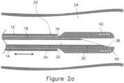
- device 10 comprises a handle or handpiece 2 and a main body shaft 12 having a secondary lumen 18 and a primary lumen 14 ( Fig. 2a ).
- the practitioner selects an appropriate procedural site having each of a primary blood vessel 24 and a secondary blood vessel 26 ( Fig. 1 ) in close proximity to one another.
- the primary blood vessel 24 comprises a vein
- the secondary blood vessel 26 comprises an artery, but the device is not limited to this arrangement.
- the main body 12 is inserted into primary vessel 24 so that the distal end 32 thereof ( Fig. 2a ) lies within the blood flow passage of the primary vessel.
- this insertion step is performed using percutaneous technique, but open surgery may also be employed.
- a piercing element 20 comprises a piercing element shaft 34, lumen 22, and a distal tip 36, and can be adjustably oriented axially within the secondary lumen 18 of a needle guide 16, and lumen 22 provides an externally communicating passage.
- a distal end 40 of the needle guide 16 comprises a blunt large diameter atraumatic tip, comprised of a polymer material, having a rounded distal edge. This distal end 40 also has features that make it visible under different imaging techniques, such as ultrasound, fluoroscopy, CT, or MRI.
- the blunt distal end 40 is manipulated to contact an inner wall of the primary vessel and to push it into desired engagement with the adjacent wall of the secondary vessel, as shown in Fig. 3a .
- the position of desired engagement is arranged to optimize the piercing step to be next described.
- the distal tip 36 of the piercing element 20 may be longitudinally extended with respect to the needle guide 16, using a slide 8 on the handle 2.
- a range of the radius of curvature may be imparted on the piercing element 20 by axially adjusting the position of the main body 12 relative to needle guide 16, using a knob 4 on the handle 2.
- a first, or straightened, position is illustrated in Fig.
- Needle guide 16 is fabricated of a material that has shape memory properties that allow it to be held in an essentially axial position indefinitely by main body shaft 12, while in the orientation shown in Fig. 2a , and can achieve an incremental increase in the radius of curvature as main body shaft 12 is retracted, as shown in Fig. 3a .
- the needle guide 16 is fabricated of a superelastic material, such as Nitinol, to achieve this curvature effect.
- the piercing element shaft 34 can be formed with a radius of curvature. The strength of the piercing element shaft 34 is such that as the main body shaft 12 is retracted the piercing element shaft 34 imparts the radius of curvature onto the needle guide 16.
- the needle guide 16 need not necessarily be made of a superelastic material for this device to function. Since the shape of the needle guide comes from the piercing element shaft 34, its shape is determined by moving the primary lumen 14 axially.
- piercing distal tip 36 is configured to have echogenic and radiopaque properties to allow the practitioner to visualize the orientation of piercing tip 36 under real time imaging guidance, and the main body 12 of device 10 is incrementally rotatable about its axis, this will allow the practitioner to more effectively aim piercing tip 36 through direct visualization as secondary blood vessel 26 is "nudged" by the atraumatic tip of the needle guide 16 of the device 10 as the main body is incrementally rotated and the radius of curvature as desired, to allow more accurate penetration from primary blood vessel 24 to secondary blood vessel 26.
- knob 8 of handle 2 is advanced to penetrate from primary blood vessel 24 through the primary vessel wall 44 to secondary blood vessel 26 through the secondary vessel wall 46. This may be done under direct imaging guidance to verify complete penetration without extending beyond the flow passage of blood vessel 26. The practitioner may also verify acceptable penetration through direct visualization of blood that flows through lumen 22 and exits through an aperture 6 of the handle 2 as shown in Fig. 1a .
- a guidewire 28 preferably having a diameter of .014" (approximately 0.0356 cm) or less, is advanced through the aperture 6 of the handle 2 until the guidewire is positioned in the blood flow path of blood vessel 26 sufficiently to allow device 10 to be removed while retaining its position in blood vessel 26.
- Fig. 7 illustrates a detail view of the configuration of the piercing tip 36 utilized in both of the illustrated devices of Figs. 1a to 5b .
- the tip is configured to have a lancet point 48 to enhance the penetration from primary blood vessel 24 to secondary blood vessel 26.
- a primary bevel 50 is ground at an angle between 12 and 20 degrees with a secondary angle between 5-20 degrees, with a rotation angle between 25-45 degrees.
- the needle grind is designed such that it pierces through the vessel wall and does not core, or cut a plug, through the vessel wall, to minimize bleeding between vessels when removed after the guidewire is placed into the secondary vessel.
- the outer diameter of the piercing member is also minimized to further reduce bleeding.
- the piercing member is oriented within the secondary lumen such that the tip of the lancet point is directed toward the adjacent secondary vessel.
- Other piercing mechanisms, or needle point grind configurations, known to those skilled in the art may be provided.
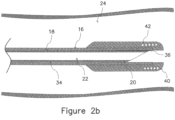
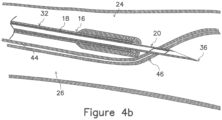
- the device of Figs. 1b , 2b , 3b , 4b , and 5b (the "B" device) is similar in most respects to that of Figs. 1a , 2a , 3a , 4a , and 5a (the "A” device), differing only in the details to be explained below. All common elements to those in the A device are identified by common reference numerals in the figures illustrating the B device, and the method sequencing shown in Figs. 2b , 3b , 4b , and 5b is similar to that shown in Figs. 2a , 3a , 4a , and 5a .
- Figs. 6 and 7 are common to both devices.
- the primary lumen 14 has been eliminated.
- the shape of the needle guide 16 is not adjustable. Thus, it remains straight, and need not be fabricated of superelastic material.
- the blunt distal end 40 may be manipulated by the practitioner to ensure that the adjacent vessel walls of the primary and secondary vessel may be pierced by an axial advancement of the piercing member, as shown in Fig. 3b .
- the knob 4 has also been eliminated, since control of the curvature of needle guide 16 is not required.
- the blunt distal end 40 of the needle guide 16 includes an alignment attachment, implant, or multiple implants embedded in or attached to the distal alignment end 40.
- a guidewire 52 is placed into the secondary blood vessel 26, as shown, wherein the guidewire 52 has an alignment tip 54.
- the alignment end 40 and alignment tip 54 each comprise a magnetic material, either entirely or as an implant or multiple implants embedded in or attached to the each respective end 40 and tip 54.
- the alignment tips 40 and 54 are established with opposite polarity, so that they are mutually attracted to one another.
- Each of the alignment members 40 and 54 discussed above may comprise, in addition to magnetic attachments or implants, proximity sensors or ultrasonic sensors, as well as any other equivalent devices or systems for facilitating alignment of two members separated by opaque tissue, where imaging alignment procedures are less effective.
- the practitioner selects an appropriate procedural site having each of a primary blood vessel 24 and a secondary blood vessel 26 in close proximity to one another.
- the primary blood vessel 24 comprises a vein
- the secondary blood vessel 26 comprises an artery, but the device is not limited to this arrangement.
- the main body 12 is inserted into primary vessel 24 so that the distal end 32 thereof ( Fig. 2a ) lies within the blood flow passage of the primary vessel.
- this insertion step is performed using percutaneous technique, but open surgery may also be employed.
- the lumen 22 provides an externally communicating passage.
- the distal end 40 of the needle guide 16, as noted above, comprises a magnetic material.
- the magnetic distal end 40 is manipulated to a position proximate to or in contact with an inner wall of the primary vessel, as shown in Fig. 8 , at a location desirable for the creation of an AVF.
- the guidewire 52 with magnetic tip 54, is maneuvered within the blood vessel 26 to the same location.
- the magnetic tips 40 and 54 once they are maneuvered to locations adequately proximate to one another, become magnetically attracted to one another through the tissue walls of the respective vessels 24, 26.
- This mutual magnetic attraction causes the tips 40 and 54 to approach one another and to come into alignment, thus also functioning to physically push the vessels 24 and 26 together and into alignment as well. This alignment is shown in Fig. 8 .
- the respective magnetic tips provide good tactile and visual feedback to the practitioner when they are engaged, permitting confidence in knowing that the vessels 24 and 26 are aligned.
- the alignment of the vessels 24 and 26 optimizes the piercing step to be next described.
- the distal tip 36 of the piercing element 20 may be longitudinally extended with respect to the needle guide 16, between a range of the radius of curvature along the axis of needle guide 16, using a slide 8 on the handle 2.
- a first, or retracted, position is illustrated in Fig. 8 .
- Fig. 9 the distal tip 36 of the needle or piercing element 20 has been extended beyond the end of needle guide 16, and through the adjacent tissue walls of each vessel 24, 26.
- the needle functions to dislodge the arterial magnet 54 by pushing and advancing the magnet 54 away from the magnetic tip 40 and advances its attached guidewire 52 as well.
- a guidewire 28 may be disposed through the procedural site and device 10 may be withdrawn, as shown in Fig. 6 and as discussed in connection with the prior embodiment. Instrumentation may then be introduced to the procedural site over the guidewire 28 to create the desired AVF, as taught and disclosed, for example, in commonly assigned U.S. Patent Nos. 9,439,710, 9,452,015 , and 9,474,562 .
Landscapes
- Health & Medical Sciences (AREA)
- Life Sciences & Earth Sciences (AREA)
- Biophysics (AREA)
- Pulmonology (AREA)
- Engineering & Computer Science (AREA)
- Anesthesiology (AREA)
- Biomedical Technology (AREA)
- Heart & Thoracic Surgery (AREA)
- Hematology (AREA)
- Animal Behavior & Ethology (AREA)
- General Health & Medical Sciences (AREA)
- Public Health (AREA)
- Veterinary Medicine (AREA)
- Surgical Instruments (AREA)
- Media Introduction/Drainage Providing Device (AREA)
Claims (5)
- Dispositif (10) permettant de créer un accès intravasculaire et la mise en place d'un fil-guide, comprenant :un corps principal (12) comportant une lumière (18) ;un élément de perçage (20) disposé dans ladite lumière (18) ;une poignée (2) fixée audit corps principal (12) et comportant un actionneur (4) pour déplacer ledit élément de perçage (20) ;un guide-aiguille (16) pour guider l'élément de perçage (20), le guide-aiguille (16) comportant une extrémité distale (40) qui comprend un matériau magnétique ; etun fil-guide (52) comportant un bout distal magnétique (54) ;dans lequel :l'extrémité distale (40) du guide-aiguille (16) et le bout distal magnétique (54) du fil-guide (52) sont des pointes d'alignement établies avec une polarité opposée, de sorte qu'ils soient mutuellement attirés l'un vers l'autre,l'élément de perçage (20) est configuré pour être déplacé distalement hors de ladite lumière (18), tandis que l'extrémité distale (40) du guide-aiguille (16) et le bout distal magnétique (54) du fil-guide (52) sont magnétiquement attirés l'un vers l'autre à travers les parois tissulaires de vaisseaux primaire et secondaire (24, 26) respectifs, et pour percer le tissu tout en étant déplacé distalement, etle bout distal magnétique (54) du fil-guide (52) est configuré pour être poussé et éloigné de l'extrémité distale (40) du guide-aiguille (16) par l'élément de perçage (20) qui entre en contact avec le bout distal magnétique (54) une fois que la pénétration du vaisseau primaire (24) vers le vaisseau secondaire (26) a été réalisée.
- Dispositif (10) selon la revendication 1, dans lequel l'élément de perçage (20) présente une pointe acérée à une extrémité (36) de celui-ci.
- Dispositif (10) selon la revendication 2, dans lequel l'élément de perçage (20) est rétractable dans la lumière de corps principal (18).
- Dispositif (10) selon la revendication 1, dans lequel l'actionneur (4) comprend un bouton rotatif.
- Dispositif (10) selon la revendication 2, dans lequel la pointe acérée comprend une pointe de lancette (48) et des biseaux primaires (50).
Applications Claiming Priority (2)
| Application Number | Priority Date | Filing Date | Title |
|---|---|---|---|
| US201662421125P | 2016-11-11 | 2016-11-11 | |
| PCT/US2017/060940 WO2018089689A1 (fr) | 2016-11-11 | 2017-11-09 | Systèmes et procédés servant à un accès intravasculaire percutané et le placement d'un fil-guide |
Publications (3)
| Publication Number | Publication Date |
|---|---|
| EP3538192A1 EP3538192A1 (fr) | 2019-09-18 |
| EP3538192A4 EP3538192A4 (fr) | 2020-09-30 |
| EP3538192B1 true EP3538192B1 (fr) | 2024-10-23 |
Family
ID=62106508
Family Applications (1)
| Application Number | Title | Priority Date | Filing Date |
|---|---|---|---|
| EP17870559.6A Active EP3538192B1 (fr) | 2016-11-11 | 2017-11-09 | Systèmes servant à un accès intravasculaire percutané et le placement d'un fil-guide |
Country Status (6)
| Country | Link |
|---|---|
| US (2) | US11207503B2 (fr) |
| EP (1) | EP3538192B1 (fr) |
| JP (1) | JP2019533539A (fr) |
| CN (1) | CN109996580A (fr) |
| AU (1) | AU2017357918A1 (fr) |
| WO (1) | WO2018089689A1 (fr) |
Families Citing this family (7)
| Publication number | Priority date | Publication date | Assignee | Title |
|---|---|---|---|---|
| CN110997036A (zh) * | 2017-06-19 | 2020-04-10 | 加利福尼亚大学董事会 | 用于无创和经皮形成动静脉瘘的装置和方法 |
| WO2020081597A1 (fr) | 2018-10-15 | 2020-04-23 | Aharon Alon S | Systèmes et procédés d'accès et de distribution par perforation magnétique |
| US11666279B2 (en) * | 2018-12-18 | 2023-06-06 | Movano Inc. | Removable smartphone case for radio wave based health monitoring that includes an alignment feature |
| CN115279282B (zh) | 2019-12-30 | 2024-12-17 | Tva医疗公司 | 用于形成瘘管的系统 |
| WO2022099246A1 (fr) | 2020-11-09 | 2022-05-12 | Venova Medical, Inc. | Implants endovasculaires ainsi que dispositifs et procédés de placement précis |
| JP2024523174A (ja) * | 2021-06-16 | 2024-06-28 | コーニンクレッカ フィリップス エヌ ヴェ | 動脈閉塞および静脈閉塞のための磁気駆動横断ツール |
| EP4556046A1 (fr) * | 2023-11-16 | 2025-05-21 | Artedrone | Système d'administration pour un dispositif médical, fil-guide, dispositif cathéter, dispositif médical et procédé de traitement d'un patient |
Family Cites Families (72)
| Publication number | Priority date | Publication date | Assignee | Title |
|---|---|---|---|---|
| JP2558584B2 (ja) | 1991-04-05 | 1996-11-27 | メトカル・インコーポレーテッド | 身体組織を切断し、凝固し、除去するための器具 |
| US5290278A (en) | 1992-10-20 | 1994-03-01 | Proclosure Inc. | Method and apparatus for applying thermal energy to luminal tissue |
| GB9307572D0 (en) | 1993-04-13 | 1993-06-02 | Gould Derek A | Transintimal recanalisation device |
| US5380292A (en) * | 1993-12-22 | 1995-01-10 | Wilson-Cook Medical, Inc. | Gastrointestinal needle mechanism |
| US6068637A (en) | 1995-10-03 | 2000-05-30 | Cedar Sinai Medical Center | Method and devices for performing vascular anastomosis |
| IL151563A0 (en) | 1995-10-13 | 2003-04-10 | Transvascular Inc | A longitudinal compression apparatus for compressing tissue |
| US6726677B1 (en) | 1995-10-13 | 2004-04-27 | Transvascular, Inc. | Stabilized tissue penetrating catheters |
| US6375615B1 (en) | 1995-10-13 | 2002-04-23 | Transvascular, Inc. | Tissue penetrating catheters having integral imaging transducers and their methods of use |
| CN1204242A (zh) | 1995-10-13 | 1999-01-06 | 血管转换公司 | 为动脉阻塞物加设旁路和/或其他经血管操作的方法和装置 |
| US6302875B1 (en) | 1996-10-11 | 2001-10-16 | Transvascular, Inc. | Catheters and related devices for forming passageways between blood vessels or other anatomical structures |
| ATE515237T1 (de) | 1995-10-13 | 2011-07-15 | Medtronic Vascular Inc | Vorrichtung und system bei einem interstitiellen transvaskulären eingriff |
| US6283983B1 (en) | 1995-10-13 | 2001-09-04 | Transvascular, Inc. | Percutaneous in-situ coronary bypass method and apparatus |
| IL125416A0 (en) | 1996-02-02 | 1999-03-12 | Transvascular Inc | Methods and apparatus for connecting openings formed in adjacent blood vessels or other anatomical structures |
| US6579311B1 (en) | 1996-02-02 | 2003-06-17 | Transvascular, Inc. | Method for interstitial transvascular intervention |
| US6709444B1 (en) | 1996-02-02 | 2004-03-23 | Transvascular, Inc. | Methods for bypassing total or near-total obstructions in arteries or other anatomical conduits |
| US5830224A (en) | 1996-03-15 | 1998-11-03 | Beth Israel Deaconess Medical Center | Catheter apparatus and methodology for generating a fistula on-demand between closely associated blood vessels at a pre-chosen anatomic site in-vivo |
| US6379319B1 (en) | 1996-10-11 | 2002-04-30 | Transvascular, Inc. | Systems and methods for directing and snaring guidewires |
| US6626901B1 (en) | 1997-03-05 | 2003-09-30 | The Trustees Of Columbia University In The City Of New York | Electrothermal instrument for sealing and joining or cutting tissue |
| WO1998046115A2 (fr) | 1997-04-11 | 1998-10-22 | Transvascular, Inc. | Procedes et appareil pour la revascularisation coronarienne directe transmyocardique |
| US6071292A (en) | 1997-06-28 | 2000-06-06 | Transvascular, Inc. | Transluminal methods and devices for closing, forming attachments to, and/or forming anastomotic junctions in, luminal anatomical structures |
| US6083223A (en) | 1997-08-28 | 2000-07-04 | Baker; James A. | Methods and apparatus for welding blood vessels |
| US8184557B2 (en) | 1997-10-21 | 2012-05-22 | Intel Corporation | Apparatus and method for computer controlled call processing applications in packet switched telephone networks |
| US6330884B1 (en) | 1997-11-14 | 2001-12-18 | Transvascular, Inc. | Deformable scaffolding multicellular stent |
| US6561998B1 (en) | 1998-04-07 | 2003-05-13 | Transvascular, Inc. | Transluminal devices, systems and methods for enlarging interstitial penetration tracts |
| US6361559B1 (en) * | 1998-06-10 | 2002-03-26 | Converge Medical, Inc. | Thermal securing anastomosis systems |
| US6102887A (en) | 1998-08-11 | 2000-08-15 | Biocardia, Inc. | Catheter drug delivery system and method for use |
| US6235027B1 (en) | 1999-01-21 | 2001-05-22 | Garrett D. Herzon | Thermal cautery surgical forceps |
| US6248117B1 (en) | 1999-04-16 | 2001-06-19 | Vital Access Corp | Anastomosis apparatus for use in intraluminally directed vascular anastomosis |
| US6488689B1 (en) | 1999-05-20 | 2002-12-03 | Aaron V. Kaplan | Methods and apparatus for transpericardial left atrial appendage closure |
| US6391038B2 (en) | 1999-07-28 | 2002-05-21 | Cardica, Inc. | Anastomosis system and method for controlling a tissue site |
| US7892246B2 (en) | 1999-07-28 | 2011-02-22 | Bioconnect Systems, Inc. | Devices and methods for interconnecting conduits and closing openings in tissue |
| US7056294B2 (en) | 2000-04-13 | 2006-06-06 | Ev3 Sunnyvale, Inc | Method and apparatus for accessing the left atrial appendage |
| US6464665B1 (en) | 2000-07-05 | 2002-10-15 | Richard R. Heuser | Catheter apparatus and method for arterializing a vein |
| US20060106278A1 (en) | 2004-05-14 | 2006-05-18 | Ample Medical, Inc. | Devices, systems, and methods for reshaping a heart valve annulus, including the use of an adjustable bridge implant system |
| US7004173B2 (en) | 2000-12-05 | 2006-02-28 | Lumend, Inc. | Catheter system for vascular re-entry from a sub-intimal space |
| US6699245B2 (en) | 2001-02-05 | 2004-03-02 | A-Med Systems, Inc. | Anastomosis system and related methods |
| US7169127B2 (en) | 2002-02-21 | 2007-01-30 | Boston Scientific Scimed, Inc. | Pressure apron direct injection catheter |
| AU2003223583A1 (en) | 2002-04-11 | 2003-10-27 | Transvascular, Inc. | Devices and methods for transluminal or transthoracic interstitial electrode placement |
| US7351247B2 (en) | 2002-09-04 | 2008-04-01 | Bioconnect Systems, Inc. | Devices and methods for interconnecting body conduits |
| JP5074765B2 (ja) | 2003-10-09 | 2012-11-14 | センターハート・インコーポレイテッド | 組織の結紮のための装置及び方法 |
| EP1694214A1 (fr) | 2003-11-06 | 2006-08-30 | NMT Medical, Inc. | Appareil de ponction transseptale |
| GB0419954D0 (en) * | 2004-09-08 | 2004-10-13 | Advotek Medical Devices Ltd | System for directing therapy |
| US20060111704A1 (en) | 2004-11-22 | 2006-05-25 | Rox Medical, Inc. | Devices, systems, and methods for energy assisted arterio-venous fistula creation |
| US8277465B2 (en) | 2004-12-15 | 2012-10-02 | Correx, Inc. | Apparatus and method for connecting a conduit to a hollow vessel |
| US8328797B2 (en) | 2004-12-23 | 2012-12-11 | C. R. Bard, Inc. | Blood vessel transecting and anastomosis |
| WO2006110734A2 (fr) | 2005-04-07 | 2006-10-19 | Sentreheart, Inc. | Procede et dispositif de ligature de tissus |
| EP1912592A4 (fr) | 2005-07-26 | 2016-01-06 | Rox Medical Inc | Dispositifs, systemes et procedes de creation de fistule arterio-veineuse |
| US20070203515A1 (en) * | 2006-01-25 | 2007-08-30 | Heuser Richard R | Catheter system for connecting adjacent blood vessels |
| US8062321B2 (en) * | 2006-01-25 | 2011-11-22 | Pq Bypass, Inc. | Catheter system for connecting adjacent blood vessels |
| US20080161904A1 (en) | 2006-01-25 | 2008-07-03 | Heuser Richard R | Connection of adjacent blood vessels |
| WO2008121278A2 (fr) | 2007-03-30 | 2008-10-09 | Sentreheart, Inc. | Dispositifs, systèmes, et procédés pour la fermeture de l'appendice auriculaire gauche |
| US8469983B2 (en) | 2007-09-20 | 2013-06-25 | Sentreheart, Inc. | Devices and methods for remote suture management |
| US7713215B2 (en) | 2008-01-31 | 2010-05-11 | Shriver Edgar L | Steering, piercing, anchoring, distending extravascular guidewire |
| US9901714B2 (en) * | 2008-08-22 | 2018-02-27 | C. R. Bard, Inc. | Catheter assembly including ECG sensor and magnetic assemblies |
| EP2368499B1 (fr) | 2008-12-24 | 2017-08-02 | Olympus Corporation | Appareil de traitement |
| EP2413815B1 (fr) | 2009-04-01 | 2018-12-12 | Sentreheart, Inc. | Dispositifs de ligature tissulaire et leurs commandes |
| WO2010124057A1 (fr) | 2009-04-22 | 2010-10-28 | Teitelbaum George P | Conduit d'entrée à répétition pour vaisseaux sanguins |
| US20120265229A1 (en) | 2009-09-03 | 2012-10-18 | Dan Rottenberg | Lancet micro-catheter |
| US20110184504A1 (en) | 2010-01-22 | 2011-07-28 | Medtronic Vascular, Inc. | Methods and Apparatus for Providing an Arteriovenous Fistula |
| CN104997574B (zh) | 2010-04-13 | 2017-06-06 | 森特里心脏股份有限公司 | 用于向心脏介入和置放装置的方法和装置 |
| EP2582314B1 (fr) | 2010-06-15 | 2019-12-18 | Avenu Medical, Inc. | Anastomose intravasculaire d'une artère à une veine, et cathéter pour soudage de tissu |
| US8951276B2 (en) | 2011-11-04 | 2015-02-10 | Avenu Medical, Inc. | Systems and methods for percutaneous intravascular access and guidewire placement |
| JP6182545B2 (ja) | 2012-02-08 | 2017-08-16 | アベヌ メディカル インコーポレイテッドAvenu Medical,Inc. | 血管内の動脈静脈吻合及び組織接合カテーテル |
| EP2841027B1 (fr) * | 2012-04-23 | 2018-08-15 | PQ Bypass, Inc. | Système de contournement d'occlusions dans une artère fémorale |
| JP6301926B2 (ja) * | 2012-08-09 | 2018-03-28 | ユニバーシティ オブ アイオワ リサーチ ファウンデーション | カテーテル、カテーテルシステム、及び組織構造を刺通する方法 |
| JP6175511B2 (ja) | 2012-11-14 | 2017-08-02 | アベヌ メディカル インコーポレイテッドAvenu Medical,Inc. | 動静脈ろうを作成するデバイス |
| CA2902064C (fr) | 2013-03-12 | 2021-06-01 | Sentreheart, Inc. | Dispositifs de ligature de tissu et procedes afferents |
| US9693820B2 (en) * | 2013-03-15 | 2017-07-04 | St. Jude Medical, Atrial Fibrillation Division, Inc. | System for detecting catheter electrodes entering into and exiting from an introducer |
| US20150057687A1 (en) | 2013-08-23 | 2015-02-26 | Cook Medical Technologies Llc | Endovascular delivery system for magnetic compression vascular anastomosis |
| US20150297259A1 (en) * | 2014-01-14 | 2015-10-22 | Volcano Corporation | Catheter assembly for vascular access site creation |
| US9545263B2 (en) | 2014-06-19 | 2017-01-17 | Limflow Gmbh | Devices and methods for treating lower extremity vasculature |
| AU2017208069B2 (en) * | 2016-01-15 | 2021-11-25 | Tva Medical, Inc. | Devices and methods for forming a fistula |
-
2017
- 2017-11-09 EP EP17870559.6A patent/EP3538192B1/fr active Active
- 2017-11-09 JP JP2019524036A patent/JP2019533539A/ja active Pending
- 2017-11-09 US US15/808,711 patent/US11207503B2/en active Active
- 2017-11-09 AU AU2017357918A patent/AU2017357918A1/en not_active Abandoned
- 2017-11-09 WO PCT/US2017/060940 patent/WO2018089689A1/fr not_active Ceased
- 2017-11-09 CN CN201780069959.2A patent/CN109996580A/zh active Pending
-
2021
- 2021-11-15 US US17/454,958 patent/US12403289B2/en active Active
Also Published As
| Publication number | Publication date |
|---|---|
| JP2019533539A (ja) | 2019-11-21 |
| EP3538192A4 (fr) | 2020-09-30 |
| US12403289B2 (en) | 2025-09-02 |
| AU2017357918A1 (en) | 2019-06-06 |
| US20180133441A1 (en) | 2018-05-17 |
| WO2018089689A1 (fr) | 2018-05-17 |
| EP3538192A1 (fr) | 2019-09-18 |
| CA3043175A1 (fr) | 2018-05-17 |
| US11207503B2 (en) | 2021-12-28 |
| US20220072280A1 (en) | 2022-03-10 |
| CN109996580A (zh) | 2019-07-09 |
Similar Documents
| Publication | Publication Date | Title |
|---|---|---|
| US12403289B2 (en) | Systems and methods for percutaneous intravascular access and guidewire placement | |
| EP2773413B1 (fr) | Systèmes d'accès intravasculaire percutané et mise en place d'un fil-guide | |
| CN108883251B (zh) | 用于推进金属丝的装置和方法 | |
| JP3493464B2 (ja) | 血管の間に通路を生成するためのカテーテル装置 | |
| US9138230B1 (en) | Systems and methods for creating arteriovenous (AV) fistulas | |
| EP4252815A2 (fr) | Dispositifs et systèmes de fenêtrage | |
| US20190183507A1 (en) | Tissue fastening tool | |
| US20090036872A1 (en) | Methods, Systems and Devices for Establising Communication Between Hollow Organs and Tissue Lumens | |
| US11786299B2 (en) | Single catheter electrode tissue cutting system for creating anastomoses | |
| CN110997036A (zh) | 用于无创和经皮形成动静脉瘘的装置和方法 | |
| EP2879753B1 (fr) | Systèmes d'accès intravasculaire percutané pour fistule artério-veineuse | |
| US20250176983A1 (en) | Magnetic Snare Endovascular Catheter System for Central Venous Stenosis | |
| CA3043175C (fr) | Systemes et procedes servant a un acces intravasculaire percutane et le placement d'un fil-guide |
Legal Events
| Date | Code | Title | Description |
|---|---|---|---|
| STAA | Information on the status of an ep patent application or granted ep patent |
Free format text: STATUS: THE INTERNATIONAL PUBLICATION HAS BEEN MADE |
|
| PUAI | Public reference made under article 153(3) epc to a published international application that has entered the european phase |
Free format text: ORIGINAL CODE: 0009012 |
|
| STAA | Information on the status of an ep patent application or granted ep patent |
Free format text: STATUS: REQUEST FOR EXAMINATION WAS MADE |
|
| 17P | Request for examination filed |
Effective date: 20190521 |
|
| AK | Designated contracting states |
Kind code of ref document: A1 Designated state(s): AL AT BE BG CH CY CZ DE DK EE ES FI FR GB GR HR HU IE IS IT LI LT LU LV MC MK MT NL NO PL PT RO RS SE SI SK SM TR |
|
| AX | Request for extension of the european patent |
Extension state: BA ME |
|
| DAV | Request for validation of the european patent (deleted) | ||
| DAX | Request for extension of the european patent (deleted) | ||
| A4 | Supplementary search report drawn up and despatched |
Effective date: 20200828 |
|
| RIC1 | Information provided on ipc code assigned before grant |
Ipc: A61M 25/01 20060101ALI20200824BHEP Ipc: A61M 25/09 20060101ALI20200824BHEP Ipc: A61M 25/06 20060101AFI20200824BHEP |
|
| STAA | Information on the status of an ep patent application or granted ep patent |
Free format text: STATUS: EXAMINATION IS IN PROGRESS |
|
| 17Q | First examination report despatched |
Effective date: 20210406 |
|
| GRAP | Despatch of communication of intention to grant a patent |
Free format text: ORIGINAL CODE: EPIDOSNIGR1 |
|
| STAA | Information on the status of an ep patent application or granted ep patent |
Free format text: STATUS: GRANT OF PATENT IS INTENDED |
|
| INTG | Intention to grant announced |
Effective date: 20240605 |
|
| GRAS | Grant fee paid |
Free format text: ORIGINAL CODE: EPIDOSNIGR3 |
|
| GRAA | (expected) grant |
Free format text: ORIGINAL CODE: 0009210 |
|
| STAA | Information on the status of an ep patent application or granted ep patent |
Free format text: STATUS: THE PATENT HAS BEEN GRANTED |
|
| AK | Designated contracting states |
Kind code of ref document: B1 Designated state(s): AL AT BE BG CH CY CZ DE DK EE ES FI FR GB GR HR HU IE IS IT LI LT LU LV MC MK MT NL NO PL PT RO RS SE SI SK SM TR |
|
| REG | Reference to a national code |
Ref country code: GB Ref legal event code: FG4D |
|
| REG | Reference to a national code |
Ref country code: CH Ref legal event code: EP |
|
| REG | Reference to a national code |
Ref country code: DE Ref legal event code: R096 Ref document number: 602017085703 Country of ref document: DE |
|
| REG | Reference to a national code |
Ref country code: IE Ref legal event code: FG4D |
|
| REG | Reference to a national code |
Ref country code: LT Ref legal event code: MG9D |
|
| REG | Reference to a national code |
Ref country code: NL Ref legal event code: MP Effective date: 20241023 |
|
| REG | Reference to a national code |
Ref country code: AT Ref legal event code: MK05 Ref document number: 1734335 Country of ref document: AT Kind code of ref document: T Effective date: 20241023 |
|
| PG25 | Lapsed in a contracting state [announced via postgrant information from national office to epo] |
Ref country code: NL Free format text: LAPSE BECAUSE OF FAILURE TO SUBMIT A TRANSLATION OF THE DESCRIPTION OR TO PAY THE FEE WITHIN THE PRESCRIBED TIME-LIMIT Effective date: 20241023 |
|
| PG25 | Lapsed in a contracting state [announced via postgrant information from national office to epo] |
Ref country code: NL Free format text: LAPSE BECAUSE OF FAILURE TO SUBMIT A TRANSLATION OF THE DESCRIPTION OR TO PAY THE FEE WITHIN THE PRESCRIBED TIME-LIMIT Effective date: 20241023 |
|
| PG25 | Lapsed in a contracting state [announced via postgrant information from national office to epo] |
Ref country code: HR Free format text: LAPSE BECAUSE OF FAILURE TO SUBMIT A TRANSLATION OF THE DESCRIPTION OR TO PAY THE FEE WITHIN THE PRESCRIBED TIME-LIMIT Effective date: 20241023 Ref country code: IS Free format text: LAPSE BECAUSE OF FAILURE TO SUBMIT A TRANSLATION OF THE DESCRIPTION OR TO PAY THE FEE WITHIN THE PRESCRIBED TIME-LIMIT Effective date: 20250223 Ref country code: PT Free format text: LAPSE BECAUSE OF FAILURE TO SUBMIT A TRANSLATION OF THE DESCRIPTION OR TO PAY THE FEE WITHIN THE PRESCRIBED TIME-LIMIT Effective date: 20250224 |
|
| PG25 | Lapsed in a contracting state [announced via postgrant information from national office to epo] |
Ref country code: FI Free format text: LAPSE BECAUSE OF FAILURE TO SUBMIT A TRANSLATION OF THE DESCRIPTION OR TO PAY THE FEE WITHIN THE PRESCRIBED TIME-LIMIT Effective date: 20241023 |
|
| PG25 | Lapsed in a contracting state [announced via postgrant information from national office to epo] |
Ref country code: BG Free format text: LAPSE BECAUSE OF FAILURE TO SUBMIT A TRANSLATION OF THE DESCRIPTION OR TO PAY THE FEE WITHIN THE PRESCRIBED TIME-LIMIT Effective date: 20241023 |
|
| PG25 | Lapsed in a contracting state [announced via postgrant information from national office to epo] |
Ref country code: ES Free format text: LAPSE BECAUSE OF FAILURE TO SUBMIT A TRANSLATION OF THE DESCRIPTION OR TO PAY THE FEE WITHIN THE PRESCRIBED TIME-LIMIT Effective date: 20241023 |
|
| PG25 | Lapsed in a contracting state [announced via postgrant information from national office to epo] |
Ref country code: NO Free format text: LAPSE BECAUSE OF FAILURE TO SUBMIT A TRANSLATION OF THE DESCRIPTION OR TO PAY THE FEE WITHIN THE PRESCRIBED TIME-LIMIT Effective date: 20250123 |
|
| PG25 | Lapsed in a contracting state [announced via postgrant information from national office to epo] |
Ref country code: GR Free format text: LAPSE BECAUSE OF FAILURE TO SUBMIT A TRANSLATION OF THE DESCRIPTION OR TO PAY THE FEE WITHIN THE PRESCRIBED TIME-LIMIT Effective date: 20250124 Ref country code: LV Free format text: LAPSE BECAUSE OF FAILURE TO SUBMIT A TRANSLATION OF THE DESCRIPTION OR TO PAY THE FEE WITHIN THE PRESCRIBED TIME-LIMIT Effective date: 20241023 Ref country code: AT Free format text: LAPSE BECAUSE OF FAILURE TO SUBMIT A TRANSLATION OF THE DESCRIPTION OR TO PAY THE FEE WITHIN THE PRESCRIBED TIME-LIMIT Effective date: 20241023 |
|
| PG25 | Lapsed in a contracting state [announced via postgrant information from national office to epo] |
Ref country code: PL Free format text: LAPSE BECAUSE OF FAILURE TO SUBMIT A TRANSLATION OF THE DESCRIPTION OR TO PAY THE FEE WITHIN THE PRESCRIBED TIME-LIMIT Effective date: 20241023 |
|
| PG25 | Lapsed in a contracting state [announced via postgrant information from national office to epo] |
Ref country code: RS Free format text: LAPSE BECAUSE OF FAILURE TO SUBMIT A TRANSLATION OF THE DESCRIPTION OR TO PAY THE FEE WITHIN THE PRESCRIBED TIME-LIMIT Effective date: 20250123 |
|
| REG | Reference to a national code |
Ref country code: CH Ref legal event code: PL |
|
| PG25 | Lapsed in a contracting state [announced via postgrant information from national office to epo] |
Ref country code: SM Free format text: LAPSE BECAUSE OF FAILURE TO SUBMIT A TRANSLATION OF THE DESCRIPTION OR TO PAY THE FEE WITHIN THE PRESCRIBED TIME-LIMIT Effective date: 20241023 |
|
| PG25 | Lapsed in a contracting state [announced via postgrant information from national office to epo] |
Ref country code: MC Free format text: LAPSE BECAUSE OF FAILURE TO SUBMIT A TRANSLATION OF THE DESCRIPTION OR TO PAY THE FEE WITHIN THE PRESCRIBED TIME-LIMIT Effective date: 20241023 |
|
| PG25 | Lapsed in a contracting state [announced via postgrant information from national office to epo] |
Ref country code: DK Free format text: LAPSE BECAUSE OF FAILURE TO SUBMIT A TRANSLATION OF THE DESCRIPTION OR TO PAY THE FEE WITHIN THE PRESCRIBED TIME-LIMIT Effective date: 20241023 |
|
| PG25 | Lapsed in a contracting state [announced via postgrant information from national office to epo] |
Ref country code: LU Free format text: LAPSE BECAUSE OF NON-PAYMENT OF DUE FEES Effective date: 20241109 |
|
| REG | Reference to a national code |
Ref country code: CH Ref legal event code: PL |
|
| PG25 | Lapsed in a contracting state [announced via postgrant information from national office to epo] |
Ref country code: EE Free format text: LAPSE BECAUSE OF FAILURE TO SUBMIT A TRANSLATION OF THE DESCRIPTION OR TO PAY THE FEE WITHIN THE PRESCRIBED TIME-LIMIT Effective date: 20241023 |
|
| PG25 | Lapsed in a contracting state [announced via postgrant information from national office to epo] |
Ref country code: CH Free format text: LAPSE BECAUSE OF NON-PAYMENT OF DUE FEES Effective date: 20241130 |
|
| PG25 | Lapsed in a contracting state [announced via postgrant information from national office to epo] |
Ref country code: RO Free format text: LAPSE BECAUSE OF FAILURE TO SUBMIT A TRANSLATION OF THE DESCRIPTION OR TO PAY THE FEE WITHIN THE PRESCRIBED TIME-LIMIT Effective date: 20241023 |
|
| REG | Reference to a national code |
Ref country code: DE Ref legal event code: R097 Ref document number: 602017085703 Country of ref document: DE |
|
| PG25 | Lapsed in a contracting state [announced via postgrant information from national office to epo] |
Ref country code: SK Free format text: LAPSE BECAUSE OF FAILURE TO SUBMIT A TRANSLATION OF THE DESCRIPTION OR TO PAY THE FEE WITHIN THE PRESCRIBED TIME-LIMIT Effective date: 20241023 |
|
| PG25 | Lapsed in a contracting state [announced via postgrant information from national office to epo] |
Ref country code: CZ Free format text: LAPSE BECAUSE OF FAILURE TO SUBMIT A TRANSLATION OF THE DESCRIPTION OR TO PAY THE FEE WITHIN THE PRESCRIBED TIME-LIMIT Effective date: 20241023 |
|
| PG25 | Lapsed in a contracting state [announced via postgrant information from national office to epo] |
Ref country code: IT Free format text: LAPSE BECAUSE OF FAILURE TO SUBMIT A TRANSLATION OF THE DESCRIPTION OR TO PAY THE FEE WITHIN THE PRESCRIBED TIME-LIMIT Effective date: 20241023 |
|
| REG | Reference to a national code |
Ref country code: BE Ref legal event code: MM Effective date: 20241130 |
|
| PLBE | No opposition filed within time limit |
Free format text: ORIGINAL CODE: 0009261 |
|
| STAA | Information on the status of an ep patent application or granted ep patent |
Free format text: STATUS: NO OPPOSITION FILED WITHIN TIME LIMIT |
|
| PG25 | Lapsed in a contracting state [announced via postgrant information from national office to epo] |
Ref country code: SE Free format text: LAPSE BECAUSE OF FAILURE TO SUBMIT A TRANSLATION OF THE DESCRIPTION OR TO PAY THE FEE WITHIN THE PRESCRIBED TIME-LIMIT Effective date: 20241023 |
|
| GBPC | Gb: european patent ceased through non-payment of renewal fee |
Effective date: 20250123 |
|
| 26N | No opposition filed |
Effective date: 20250724 |
|
| PG25 | Lapsed in a contracting state [announced via postgrant information from national office to epo] |
Ref country code: GB Free format text: LAPSE BECAUSE OF NON-PAYMENT OF DUE FEES Effective date: 20250123 Ref country code: BE Free format text: LAPSE BECAUSE OF NON-PAYMENT OF DUE FEES Effective date: 20241130 |
|
| PG25 | Lapsed in a contracting state [announced via postgrant information from national office to epo] |
Ref country code: IE Free format text: LAPSE BECAUSE OF NON-PAYMENT OF DUE FEES Effective date: 20241109 |
|
| PGFP | Annual fee paid to national office [announced via postgrant information from national office to epo] |
Ref country code: DE Payment date: 20251022 Year of fee payment: 9 |
|
| PGFP | Annual fee paid to national office [announced via postgrant information from national office to epo] |
Ref country code: FR Payment date: 20251022 Year of fee payment: 9 |
|
| PG25 | Lapsed in a contracting state [announced via postgrant information from national office to epo] |
Ref country code: HU Free format text: LAPSE BECAUSE OF FAILURE TO SUBMIT A TRANSLATION OF THE DESCRIPTION OR TO PAY THE FEE WITHIN THE PRESCRIBED TIME-LIMIT; INVALID AB INITIO Effective date: 20171109 |
|
| PG25 | Lapsed in a contracting state [announced via postgrant information from national office to epo] |
Ref country code: CY Free format text: LAPSE BECAUSE OF FAILURE TO SUBMIT A TRANSLATION OF THE DESCRIPTION OR TO PAY THE FEE WITHIN THE PRESCRIBED TIME-LIMIT; INVALID AB INITIO Effective date: 20171109 |