EP3538965B1 - Système de sécurité pour le fonctionnement d'un véhicule aérien sans pilote - Google Patents
Système de sécurité pour le fonctionnement d'un véhicule aérien sans pilote Download PDFInfo
- Publication number
- EP3538965B1 EP3538965B1 EP17869393.3A EP17869393A EP3538965B1 EP 3538965 B1 EP3538965 B1 EP 3538965B1 EP 17869393 A EP17869393 A EP 17869393A EP 3538965 B1 EP3538965 B1 EP 3538965B1
- Authority
- EP
- European Patent Office
- Prior art keywords
- uav
- activator
- command
- controller
- button
- Prior art date
- Legal status (The legal status is an assumption and is not a legal conclusion. Google has not performed a legal analysis and makes no representation as to the accuracy of the status listed.)
- Active
Links
Images


Classifications
-
- G—PHYSICS
- G05—CONTROLLING; REGULATING
- G05D—SYSTEMS FOR CONTROLLING OR REGULATING NON-ELECTRIC VARIABLES
- G05D1/00—Control of position, course, altitude or attitude of land, water, air or space vehicles, e.g. using automatic pilots
- G05D1/0011—Control of position, course, altitude or attitude of land, water, air or space vehicles, e.g. using automatic pilots associated with a remote control arrangement
- G05D1/0016—Control of position, course, altitude or attitude of land, water, air or space vehicles, e.g. using automatic pilots associated with a remote control arrangement characterised by the operator's input device
-
- G—PHYSICS
- G05—CONTROLLING; REGULATING
- G05D—SYSTEMS FOR CONTROLLING OR REGULATING NON-ELECTRIC VARIABLES
- G05D1/00—Control of position, course, altitude or attitude of land, water, air or space vehicles, e.g. using automatic pilots
- G05D1/0055—Control of position, course, altitude or attitude of land, water, air or space vehicles, e.g. using automatic pilots with safety arrangements
-
- G—PHYSICS
- G05—CONTROLLING; REGULATING
- G05D—SYSTEMS FOR CONTROLLING OR REGULATING NON-ELECTRIC VARIABLES
- G05D1/00—Control of position, course, altitude or attitude of land, water, air or space vehicles, e.g. using automatic pilots
- G05D1/60—Intended control result
- G05D1/617—Safety or protection, e.g. defining protection zones around obstacles or avoiding hazards
-
- B—PERFORMING OPERATIONS; TRANSPORTING
- B64—AIRCRAFT; AVIATION; COSMONAUTICS
- B64C—AEROPLANES; HELICOPTERS
- B64C39/00—Aircraft not otherwise provided for
- B64C39/02—Aircraft not otherwise provided for characterised by special use
- B64C39/024—Aircraft not otherwise provided for characterised by special use of the remote controlled vehicle type, i.e. RPV
-
- B—PERFORMING OPERATIONS; TRANSPORTING
- B64—AIRCRAFT; AVIATION; COSMONAUTICS
- B64U—UNMANNED AERIAL VEHICLES [UAV]; EQUIPMENT THEREFOR
- B64U10/00—Type of UAV
- B64U10/20—Vertical take-off and landing [VTOL] aircraft
-
- G—PHYSICS
- G05—CONTROLLING; REGULATING
- G05D—SYSTEMS FOR CONTROLLING OR REGULATING NON-ELECTRIC VARIABLES
- G05D1/00—Control of position, course, altitude or attitude of land, water, air or space vehicles, e.g. using automatic pilots
- G05D1/20—Control system inputs
- G05D1/22—Command input arrangements
- G05D1/221—Remote-control arrangements
- G05D1/222—Remote-control arrangements operated by humans
- G05D1/223—Command input arrangements on the remote controller, e.g. joysticks or touch screens
-
- G—PHYSICS
- G05—CONTROLLING; REGULATING
- G05D—SYSTEMS FOR CONTROLLING OR REGULATING NON-ELECTRIC VARIABLES
- G05D1/00—Control of position, course, altitude or attitude of land, water, air or space vehicles, e.g. using automatic pilots
- G05D1/80—Arrangements for reacting to or preventing system or operator failure
-
- B—PERFORMING OPERATIONS; TRANSPORTING
- B64—AIRCRAFT; AVIATION; COSMONAUTICS
- B64U—UNMANNED AERIAL VEHICLES [UAV]; EQUIPMENT THEREFOR
- B64U10/00—Type of UAV
- B64U10/10—Rotorcrafts
-
- B—PERFORMING OPERATIONS; TRANSPORTING
- B64—AIRCRAFT; AVIATION; COSMONAUTICS
- B64U—UNMANNED AERIAL VEHICLES [UAV]; EQUIPMENT THEREFOR
- B64U10/00—Type of UAV
- B64U10/25—Fixed-wing aircraft
-
- B—PERFORMING OPERATIONS; TRANSPORTING
- B64—AIRCRAFT; AVIATION; COSMONAUTICS
- B64U—UNMANNED AERIAL VEHICLES [UAV]; EQUIPMENT THEREFOR
- B64U2101/00—UAVs specially adapted for particular uses or applications
- B64U2101/30—UAVs specially adapted for particular uses or applications for imaging, photography or videography
-
- B—PERFORMING OPERATIONS; TRANSPORTING
- B64—AIRCRAFT; AVIATION; COSMONAUTICS
- B64U—UNMANNED AERIAL VEHICLES [UAV]; EQUIPMENT THEREFOR
- B64U2201/00—UAVs characterised by their flight controls
- B64U2201/10—UAVs characterised by their flight controls autonomous, i.e. by navigating independently from ground or air stations, e.g. by using inertial navigation systems [INS]
-
- B—PERFORMING OPERATIONS; TRANSPORTING
- B64—AIRCRAFT; AVIATION; COSMONAUTICS
- B64U—UNMANNED AERIAL VEHICLES [UAV]; EQUIPMENT THEREFOR
- B64U2201/00—UAVs characterised by their flight controls
- B64U2201/20—Remote controls
-
- B—PERFORMING OPERATIONS; TRANSPORTING
- B64—AIRCRAFT; AVIATION; COSMONAUTICS
- B64U—UNMANNED AERIAL VEHICLES [UAV]; EQUIPMENT THEREFOR
- B64U30/00—Means for producing lift; Empennages; Arrangements thereof
- B64U30/10—Wings
-
- B—PERFORMING OPERATIONS; TRANSPORTING
- B64—AIRCRAFT; AVIATION; COSMONAUTICS
- B64U—UNMANNED AERIAL VEHICLES [UAV]; EQUIPMENT THEREFOR
- B64U30/00—Means for producing lift; Empennages; Arrangements thereof
- B64U30/20—Rotors; Rotor supports
-
- B—PERFORMING OPERATIONS; TRANSPORTING
- B64—AIRCRAFT; AVIATION; COSMONAUTICS
- B64U—UNMANNED AERIAL VEHICLES [UAV]; EQUIPMENT THEREFOR
- B64U70/00—Launching, take-off or landing arrangements
-
- B—PERFORMING OPERATIONS; TRANSPORTING
- B64—AIRCRAFT; AVIATION; COSMONAUTICS
- B64U—UNMANNED AERIAL VEHICLES [UAV]; EQUIPMENT THEREFOR
- B64U70/00—Launching, take-off or landing arrangements
- B64U70/80—Vertical take-off or landing, e.g. using rockets
-
- B—PERFORMING OPERATIONS; TRANSPORTING
- B64—AIRCRAFT; AVIATION; COSMONAUTICS
- B64U—UNMANNED AERIAL VEHICLES [UAV]; EQUIPMENT THEREFOR
- B64U80/00—Transport or storage specially adapted for UAVs
- B64U80/20—Transport or storage specially adapted for UAVs with arrangements for servicing the UAV
- B64U80/25—Transport or storage specially adapted for UAVs with arrangements for servicing the UAV for recharging batteries; for refuelling
-
- B—PERFORMING OPERATIONS; TRANSPORTING
- B64—AIRCRAFT; AVIATION; COSMONAUTICS
- B64U—UNMANNED AERIAL VEHICLES [UAV]; EQUIPMENT THEREFOR
- B64U80/00—Transport or storage specially adapted for UAVs
- B64U80/30—Transport or storage specially adapted for UAVs with arrangements for data transmission
-
- G—PHYSICS
- G05—CONTROLLING; REGULATING
- G05D—SYSTEMS FOR CONTROLLING OR REGULATING NON-ELECTRIC VARIABLES
- G05D2101/00—Details of software or hardware architectures used for the control of position
- G05D2101/10—Details of software or hardware architectures used for the control of position using artificial intelligence [AI] techniques
-
- G—PHYSICS
- G05—CONTROLLING; REGULATING
- G05D—SYSTEMS FOR CONTROLLING OR REGULATING NON-ELECTRIC VARIABLES
- G05D2109/00—Types of controlled vehicles
- G05D2109/20—Aircraft, e.g. drones
-
- G—PHYSICS
- G06—COMPUTING OR CALCULATING; COUNTING
- G06F—ELECTRIC DIGITAL DATA PROCESSING
- G06F3/00—Input arrangements for transferring data to be processed into a form capable of being handled by the computer; Output arrangements for transferring data from processing unit to output unit, e.g. interface arrangements
- G06F3/01—Input arrangements or combined input and output arrangements for interaction between user and computer
- G06F3/048—Interaction techniques based on graphical user interfaces [GUI]
- G06F3/0487—Interaction techniques based on graphical user interfaces [GUI] using specific features provided by the input device, e.g. functions controlled by the rotation of a mouse with dual sensing arrangements, or of the nature of the input device, e.g. tap gestures based on pressure sensed by a digitiser
- G06F3/0488—Interaction techniques based on graphical user interfaces [GUI] using specific features provided by the input device, e.g. functions controlled by the rotation of a mouse with dual sensing arrangements, or of the nature of the input device, e.g. tap gestures based on pressure sensed by a digitiser using a touch-screen or digitiser, e.g. input of commands through traced gestures
- G06F3/04883—Interaction techniques based on graphical user interfaces [GUI] using specific features provided by the input device, e.g. functions controlled by the rotation of a mouse with dual sensing arrangements, or of the nature of the input device, e.g. tap gestures based on pressure sensed by a digitiser using a touch-screen or digitiser, e.g. input of commands through traced gestures for inputting data by handwriting, e.g. gesture or text
-
- H—ELECTRICITY
- H04—ELECTRIC COMMUNICATION TECHNIQUE
- H04N—PICTORIAL COMMUNICATION, e.g. TELEVISION
- H04N7/00—Television systems
- H04N7/18—Closed-circuit television [CCTV] systems, i.e. systems in which the video signal is not broadcast
- H04N7/183—Closed-circuit television [CCTV] systems, i.e. systems in which the video signal is not broadcast for receiving images from a single remote source
- H04N7/185—Closed-circuit television [CCTV] systems, i.e. systems in which the video signal is not broadcast for receiving images from a single remote source from a mobile camera, e.g. for remote control
Definitions
- Embodiments relate generally to methods of commanding unmanned aerial vehicles (UAVs).
- UAVs unmanned aerial vehicles
- the device comprises means controlled by a touch zone forming an activation/deactivation button to cause the drone piloting mode to switch in alternation between: i) an activation mode in which a self-contained stabilizer system of the drone is activated, and ii) a deactivation mode in which the self-contained stabilizer system of the drone is deactivated.
- Additional method embodiments may include: receiving, by the UAV, the UAV command; and executing the received UAV command on the UAV.
- the UAV command may be sent if the first activator is selected prior to the selection of the second activator.
- Additional method embodiments may include: determining, by the controller, a remaining flight time based on a battery state of charge needed by the UAV to return to and land at a launch location; and presenting the remaining flight time on the display of the controller. Additional method embodiments may include: determining, by the controller, a position of the UAV relative to the controller; and presenting a wayfinder on the display of the controller, wherein the wayfinder is oriented toward the position of the UAV.
- the selected UAV command may be a return and land command, where the first activator may be a button, where the second activator may be a horizontal slider, and wherein selecting the second activator comprises sliding a button horizontally in the slider relative to a display of the controller.
- the return and land command may direct the UAV to land at a location it launched from.
- the method may include: determining, by a processor of an unmanned aerial vehicle (UAV), a remaining battery state of charge needed by the UAV to return to and land at a launch location; and commanding, by the processor of the UAV, the UAV to return to and land on the launch location if the determined remaining battery state of charge is within a set limit.
- the method may further include: commanding, by the processor of the UAV, the UAV to land now at the UAV current location if the determined remaining battery state of charge is under a set limit for returning and landing at the launch location.
- the method may further include: determining, by the processor of the UAV, if a fault condition has occurred; and commanding, by the processor of the UAV, the UAV to at least one of: return to and land on the launch location and land now at the UAV current location.
- the disclosed safety system for the operation of an automatic or autonomous flying UAV is configured to prevent or limit unintended activation of a critical action, such as the initiation and/or termination of flight operations of the UAV. This is achieved by the system requiring that the user to manipulate or operate more than one separate activator before the desired event or action commences. At least one of these activators may be a slider or swiping bar.
- the safety system may initiate a set of actions without user interaction in order to preserve the safest outcome possible given the circumstances.
- the initiation of flight may include the vertical take-off of a UAV.
- the termination of flight may include a vertical landing either at, or near, the original take-off location.
- This landing maneuver may be referred to as a return to home (RTH), return home, return to launch, or return to base (RTB) termination.
- RTH return to home
- RTB return to base
- the UAV may also land at a location relatively near the UAV's flight position upon termination of flight.
- This landing maneuver may be referred to as a land now, land immediate, or land immediately termination, which may be useful in emergency situations.
- a more severe example of the termination of flight may be an emergency stop command that stops all propulsion of the aircraft. This final action would only be used in a more extreme safety event, e.g., a tumbling out-of-control aircraft or unintended controlled flight into terrain.
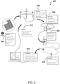
- FIG. 1A depicts an exemplary autonomous vertical take-off and landing (VTOL) unmanned aerial vehicle (UAV) 100 with a set of indicators 102, e.g., a light bar, positioned on an exterior of the UAV.
- FIG. 1B depicts an exemplary controller 104 for operating the UAV 100 of FIG. 1A from a distance.
- the UAV 100 may have a set of propellers or rotors 106 with motors 108 in motor pods 110 positioned upward at the wingtips. There may be four rotors and corresponding motor pods with two of them unseen and positioned directly behind those shown, such that there is a pair on either side of each wing tip to provide a quad-rotor configuration.
- the UAV may have a processor with addressable memory to control one or more functions of the UAV, receive commands from the controller 104 via a receiver or transceiver, and send data to the controller 104 or other devices via a transmitter or receiver.
- the UAV 100 may include a UAV state monitor that may include the use of any of a variety of sensors, such as a gyroscope, an accelerometer, a pressure sensors, an Inertial Measurement Unit (IMU), an Inertial Navigation System (INS), a compass, a global positioning satellite (GPS) unit, an optical sensor, a radar, a sonic sensor, and a battery state-of-charge sensor.
- sensors such as a gyroscope, an accelerometer, a pressure sensors, an Inertial Measurement Unit (IMU), an Inertial Navigation System (INS), a compass, a global positioning satellite (GPS) unit, an optical sensor, a radar, a sonic sensor, and a battery state-of-charge sensor.
- GPS global positioning satellite
- the measurements from these sensors may be tracked and compared by the UAV's processor against a set of limits or other values to determine if the UAV is properly positioned to maintain and continue the flight.
- the UAV processor may terminate the flight to maintain or maximize safe operations. Additionally, the UAV processor may execute a set of actions dynamically based on data received from the UAV state monitor with or without a connecting to the system controller 104.
- the system controller 104 may have a display or screen 112 for operating the UAV 100 from a distance.
- the controller 104 may include a controller processor, addressable memory, and transmitters/receivers for establishing a connection via a communication channel.
- the display 112 may be a flat panel touch screen that projects variable control activators, e.g., graphic buttons, switches, knobs, and sliders, to control the operation of the UAV 100.
- the controller processor may convert the user inputs to commands to be sent by the communication channel, e.g., a wired or wireless connection to the UAV 100 and provide a graphical display of the operation of the UAV 100, such as images transmitted by the UAV 100 and/or other operational information.
- the controller 104 may be handheld and may include any of a variety of position sensors such as gyroscopes and accelerometers and cameras. While a tablet is shown, other computing devices may be used in its place, such as a smartphone, a laptop, desktop, etc.
- FIG. 1C depicts a set of indicator lights for the UAV of FIG. 1A during various operating conditions.
- the lights may have a slow pulsing or breathing sequence 114 to indicate that the UAV is ready for flight but is not yet operating.
- the lights may flash green 116. If an error or fault occurs, the lights may flash red 118.
- the lights may chase up 120.
- the lights may chase down 124.
- the lights may scan 126.
- the various colors and patterns of the indicator lights may provide and convey visual confirmation to a user of the UAV, status from a safe operating distance.
- the user is alerted that the UAV may be in startup mode and indicating that the user has time to move a safe distance from the UAV. If the UAV lands with flashing red lights 118, the user is alerted that an error or fault has occurred and may proceed with diagnostics to determine the problem prior to a next flight of the UAV.
- FIG. 3 depicts a vertical take-off and transition to horizontal flight of the exemplary VTOL UAV 100 of FIG. 1A .
- the UAV 100 may transition from vertical flight to horizontal flight by varying the thrust produced by its motors.
- the UAV 100 is in a first position 301 on the ground ready for vertical take-off.
- An on-board controller having a processor and addressable memory may send a signal to the motors to produce thrust needed for vertical take-off and subsequent adjustments to thrust during flight.
- Flight control may be autonomous, pre-programmed, and/or controlled by an external user at a ground control system.
- Top motors 310 create top thrust 314, and bottom motors 320 create bottom thrust 324.
- the top thrust 314 and bottom thrust 324 may be substantially equal.
- the top thrust 314 and the bottom thrust 324 are depicted as angled based on the angles of the respective motors 310, 320 to have both a vertical and a lateral component.
- FIG. 4A depicts a visual display screen 400 for the controller of FIG. 1B for launching the UAV of FIG. 1A .
- the display screen may also be used on an auxiliary device, second controller, or any number of mirrored displays.
- the screen 400 may include a launch activator or button 420 positioned in a slider 410 along with a lock activator or button 430.
- the system may require that the lock button 430 be activated, i.e., pressed, simultaneously with, or sequentially with, the sliding of the launch button 420 through, or at least substantially through, the length of the slider 410.
- the required dual action with simultaneous sliding of the button 420 further reduces the potential for an unintended activation. Moving the button 420 by itself and without pressing the lock button at the same time will not activate the launch of the UAV.
- the button 420 may or may not move without the lock button being activated. Accordingly, a launch may not be initiated without the depression of the lock button 430.
- the lock button 430 may be configured to retain its unlocked position after being pressed until the launch button 420 is activated, which may allow for a single finger or non-simultaneous operation of the buttons 420, 430.
- the screen may include an indicator 440 for the final position of the button 420 in the slider 410.
- the movement of the button 420 in the slider 410 mirrors the action of the UAV, i.e., the UAV is moving upward in a vertical launch as the button 420 is moving upward in the slider. This mirroring of the action ensures that the user does not utilize an incorrect screen.
- FIG. 4B depicts a user 402 interacting with the screen 400 of FIG. 4A to launch the UAV of FIG. 1A .
- the user 402 slides the launch button 420 in the slider 410.
- the user 402 may need to concurrently depress the lock button 430 at the same time or have pressed the lock button 430 before sliding the launch button 420.
- An indicator 404 such as an arrow, may appear once the user presses the launch button 420 to indicate the direction to slide the launch button 420 in the slider 410 to launch the UAV.
- the launch slider 420 may be arranged in a vertical orientation, relative to the screen or display 400.
- This intuitive operation may be enhanced by the addition of a graphic in or about the slider indicating the sky, or otherwise, such as an image of the sun as an indicator 440 that the user moves the launch button 420 over.
- a tab may be used as an emergency stop tab 602, which when activated or pressed will take the user to an emergency stop screen, which is shown in FIGS. 10A-10B .
- Another tab is a land now tab 604, which when activated or pressed will take the user to a land now screen, which is shown in FIGS. 9A-9B .
- a third tab is a return & land tab 606, which when activated or pressed will take the user to a return and land screen, which is shown in FIGS. 8A-8B .
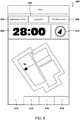
- the screen 600 may also include a wayfinder 610.
- the wayfinder 610 may point in the direction of the UAV relative to the controller. While the operator of the UAV should maintain constant line of sight, when in the air, the wayfinder 610 provides security in case the operator temporarily loses track of the UAV in their line of sign.
- the wayfinder 610 may also be used to locate the UAV in the event of a land now command.
- the wayfinder 610 may be most accurate when the controller is held parallel to the ground.
- the wayfinder 610 may use a combination of the UAV location and an orientation of the controller to determine the direction of the indicator of the wayfinder 610.
- the screen 600 may have one or more tabs 612, 614, 616, 618 to access one or more features of the system.
- the user may use these tabs 612, 614, 616, 618 to switch between a map view, an annotation view allowing the user to annotate the map view, a gallery including one or more pictures, videos, or data captured by the UAV, and additional information such as a user guide or tips.
- the survey boundary 502, 504, 506 lines indicate where the UAV will perform its scanning operations broken down into individual segments, such as segments 704, 706.
- the survey boundaries may be determined prior to flight during the user's mission planning either by using a controller, such as controller 120 and/or through an online portal, as in FIG. 5 .
- the surrounding polygons around the survey boundaries indicate the airspace 508 required for the UAV to turn around between scanning passes. This surrounding area 508 is therefore part of an overfly zone but is not imaged or scanned.
- the flight operations of the UAV may conclude when the UAV has covered and obtained data on all of the land within survey boundary 502, 504, 506. The UAV will then return to the landing location 510. Any of the three contingency actions disclosed herein may conclude the flight earlier than planned, such as, if an error or fault has occurred.
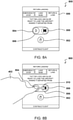
- Display screen or window 800 is displayed to a user on the controller of FIG. 1B or similar device.
- the screen 800 may be the next screen displayed to the user immediately after activation of the return & land tab 606 on the flight operation screen of FIG. 6 .
- the screen 800 may comprise a lock button 802 that must be pressed or held concurrently with a return and land activator or button 804 positioned in a slider 806.
- the system may require the sliding of the return and land button 804 through, or at least substantially through, the length of the slider 806. The required sliding of the button 804 further reduces the potential for an unintended activation.
- the user may have to perform a multi-step operation. For example, a three-step operation of first activating the return & land tab 606, pressing or holding the lock button 802, and then on screen 800 sliding the button 804 through the slider 806.
- FIG. 8B depicts a user 402 interacting with the screen 800 of FIG. 8A to land the UAV of FIG. 1A to an original departure location.
- the user 402 may slide the return and land button 804 in the slider 806.
- the user 402 may need to concurrently depress the lock button 802 at the same time or have pressed the lock button 802 before sliding the return and land button 804 to enable the return and land operation.
- An indicator 810 such as an arrow, may appear once the user presses the return and land button 804 and/or the lock button 802 to indicate the direction to slide the return and land button 804 in the slider 806 to return and land the UAV to where it departed from.
- the return and land slider 806 may be arranged in a horizontal orientation relative to the screen or display 800.
- This intuitive operation may be enhanced by the addition of a graphic in or about the slider indicating a landing location, or otherwise, such as an image of a helicopter landing pad as an indicator 808 that the user needs to move the return and land button 804 over.
- the user has to perform a multi-step operation. For example, a two-step operation of first activating the land now tab 604, and then sliding the button 902 on the screen 900 through the slider 904. There may be a three-step operation of activating the land now tab 604, pressing and/or holding a lock button 906, and then sliding the land now button 902 through the slider 904 to a set location, which may be marked with an indicator 908, such as a flat line for the ground.
- an indicator 908 such as a flat line for the ground.
- FIG. 9B depicts a user interacting with the screen 900 of FIG. 9A to land the UAV of FIG. 1A at the current location of the UAV.
- the user 402 may slide the land now button 902 in the slider 904 to effect the landing of the UAV.
- the user 402 may need to concurrently depress the lock button 906 at the same time or have pressed the lock button 906 before sliding the land now button 902.
- An indicator 910 such as an arrow, may appear once the user presses the land now button 902 and/or the lock button 906 to indicate the direction to slide the land now button 902 in the slider 904, to land the UAV at its current location.
- the land now slider 904 may be arranged in a vertical orientation, relative to the screen or display 900.
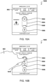
- FIG. 10A depicts a visual display screen 1000 for the controller of FIG. 1B for effecting an emergency stop of the UAV of FIG. 1A .
- the screen 1000 may be the next screen displayed to the user immediately after activation of the emergency stop tab 602.
- the screen 1000 may include an emergency stop activator or button 1002 positioned in a slider 1004.
- the sliding of the emergency land button 1002 through, or at least substantially through, the length of the slider 1004 may be required. The required sliding of the button 1002 further reduces the potential for an unintended activation.
- the arrangement of the emergency stop slider 1004 in a vertical orientation, relative to the screen or display 1008, and the indication of a slide direction downward may correspond to the UAV stopping and falling to the ground at its present location.
- the user is showing in the figure as moving the button 1002 downward to follow or mimic the operation of the UAV falling to the ground without any substantial, or further, horizontal movement from its then current location.
- This intuitive operation may be enhanced by the addition of a graphic in or about the slider indicating 1008 a landing location, such as an image of a stylized flat landing location that the user moves the emergency stop button 1002 over.
- the vertical movement of the emergency stop button 1002 and slider 1004 distinguishes from the horizontal orientation of the return and land button as slider, as shown in FIGS.
- the change in orientation ensures that a user does not accidentally land the UAV at its present location when the user wants the UAV to return to the location from which it launched.
- the emergency stop button 1002 and slider 1004 may be distinguished from the land now button and slider, as shown in FIGS. 9A-9B , by, for example, additional warnings, color coding of the screens, a visual warning, etc. While the land now button acts to vertically land the UAV in its present location, the emergency stop button 1002 and slider 1004 act to cut power to the UAV, which may cause damage or complete loss of the UAV.
- the emergency stop capability may be necessary in instances where the UAV has encountered a severe fault, is out of control, or other scenarios where the emergency stop is necessitated.
- FIG. 10B depicts a user 402 interacting with the screen 1000 of FIG. 10A to effect the emergency stop of the UAV of FIG. 1A .
- the user 402 is shown sliding the emergency stop button 1002 in the slider 1004.
- the user 402 may need to concurrently depress the lock button 1006 at the same time or have pressed the lock button 1006 before sliding the emergency stop button 1002.
- An indicator 1010 such as an arrow, may appear once the user presses the emergency stop button 1002 and/or the lock button 1006 to indicate the direction to slide the emergency stop button 1002 in the slider 1004 to cut power to the UAV motors at its current location.
- the emergency stop slider 1004 is arranged in a vertical orientation, relative to the screen or display 1000.
- This intuitive operation may be enhanced by the addition of a graphic in or about the slider indicating a landing location, or otherwise, such as an image of a flat ground as an indicator 1008 that the user moves the emergency stop button 1002 over.
- FIG. 11 depicts a flowchart of a method 1100 of operating the UAV of FIG. 1A with a safety system via the controller of FIG. 1B .
- An autonomous flying UAV such as in FIG. 1A , may be positioned on the ground in a pre-flight state without the rotor motors operating (step 1102).
- the UAV may be operated by a user via a wireless controller, such as the controller of FIG. 1B .
- the UAV may initiate operation by the user operating a first activator and second activator on the controller (step 1104). Activating only one of the two activators alone will not initiate operation of the UAV.
- At least one of the activators may be a slider.
- the controller may process the operation of the first activator, second activator, and optionally third activator, and send a wireless signal to the UAV to initiate operation of the UAV (step 1106).
- the processor of the UAV may receive the signal from the controller to initiate operation of the UAV to execute the command (step 1108).
- the UAV processor may then command the UAV motors to turn the attached propellers at a low speed to limit damage in the event of contact with any object or article (step 1110).
- the slow start-up of the rotors may also provide a warning to the user and/or any individuals near the UAV that the UAV is about to launch and that they should move a safe distance from the UAV.
- the speed of the propellers may be adjusted during this warning step, where the speed may vary depending on the distance of the controller to the UAV. That is, the system including the UAV and speed of any propeller thereof, may be adjusted during this operation, to be sufficient to warn any person in the vicinity of the UAV.
- This warning may occur prior to, subsequent to, or simultaneously with the warning lights (step 1112) or monitoring sensors (step 1114).
- the UAV processor may then turn on warning lights on the UAV (step 1112).
- the UAV processor may begin monitoring sensors to determine the state of the UAV, to terminate operation of the UAV in the event the UAV state exceeds predefined limits (step 1114). This monitoring may include operational hazards, unsafe conditions, or crash detection monitoring.
- the UAV state monitor may include the use of any of a variety of sensors, such as gyroscopes, accelerometers, pressure sensors, Inertial Measurement Unit (IMU), Inertial Navigation System (INS), compasses, global positioning satellite (GPS) units, optical (visual flow) sensors, radar, sonic sensors, battery energy estimates, servo actuator current, motor current, data quality, and the like.
- the measurements from such sensors are then tracked and compared by the UAV's processor against a set of limits or other values to determine if the UAV is properly positioned to maintain and continue the flight.
- the UAV state monitor determines that the UAV has, or is going to, surpass a set of defined limits
- the UAV processor may terminate the flight to maintain or maximize safe operations.
- the UAV's processor is able to compare derived values for the aircraft health data against what is required for the flight.
- the UAV processor may verify that the aircraft battery is reporting sufficient battery energy to execute the planned mission, where the processor may be configured to monitor a variable energy threshold based on the size of the planned mission area and hence against the required battery energy.
- the battery level may not support completion of the current planned mission and therefore, the UAV processor may redirect the UAV in a different route to achieve as much of the planned mission as possible, this being based on the battery level left and prior usage of the battery in the same mission. Accordingly, by use of previous information and state of the UAV system, a hysteresis system may be implemented where a current state of the system and output is not a strict function of the corresponding input, but also depends on the previously collected data.
- the UAV processor may then command an increased speed of the motors and propellers to begin flight of the UAV (step 1116). If needed, the flight may be terminated by operating a first activator and a second activator on the controller (step 1118). Activating only one of the two activators alone may not terminate the flight of the UAV. At least one of the activators may be a slider. Three activators may be required, e.g., selecting a flight termination tab, pressing and/or holding a lock button, and sliding a button in a slider.
- FIG. 12 depicts an exemplary safety system 1200 for the UAV 100 of FIG. 1A .
- the UAV may start from a launch location 1202 on the ground 1203.
- the launch location 1202 may be a UAV pod that provides battery charging for the UAV 100 and/or data transfer from the UAV following a mission.
- the UAV 100 may follow a flight path 1204 from vertical take-off to horizontal flight.
- the UAV 100 may use horizontal flight to maximize flight time and the area that may be imaged by one or more sensors on the UAV 100.
- the user 402 may use the controller 104 to monitor and control the UAV 100.
- the user 402 may initiate a vertical launch of the UAV 100 by two or more activators on the controller 104, as in FIGS. 4A-4B .
- the user may select a launch window, press or hold a lock button, and slide a launch button in a slider to launch the UAV 100.
- the launch button may be slid vertically upwards relative to the screen of the controller to match the vertical take-off of the UAV 100.
- the user 402 may avoid an accidental launch of the UAV 100.
- the UAV 100 Prior to launch, the UAV 100 may emit one or more warnings, such as indicator lights as shown in FIG.
- an audible warning from a speaker, the motors, or the controller, and/or an initial slow turning of the rotors or propellers of the UAV 100 Since the user 402 may need to be positioned a safe distance 1206 from the UAV launch location 1206, the one or more warnings prior to launch may ensure that the user 402 or any other individuals are not too close to the UAV 100 at launch. If the user 402 or any other individual is too close to the UAV 100, the warnings provide time to move a safe distance away and/or to terminate the launch.
- the user 402 may send one or more flight termination commands 1208 to the UAV 100 via the controller 104.
- the UAV 100 may send data 1210 to the controller 104 during flight.
- the UAV data may include sensed information, UAV status, any errors or faults, time to land, sensor status, location of the UAV, etc.
- the UAV 100 may determine a wind speed and/or direction by launching vertically, hovering, and calculating a wind speed and/or direction based on the movement of the UAV 100 relative to the ground 1203 and/or launch location 1202 while hovering.
- the UAV 100 may use this calculated wind speed and/or direction to determine an optimized flight path 1204 and/or determine a time to land.
- the UAV may send a signal to the controller indicating that based on the UAV processor calculations, the current flight path may not be achievable and accordingly, request that a user at the controller initiate a land now or return and land action.
- a processor of the UAV 100 may continuously calculate the energy required to return to and land 1212 on the launch location 1202. The processor may also continuously calculate the energy required to perform a land now 1214 operation at its current location. If the processor determines that the UAV 100 has just enough battery to return and land 1212, the processor may cause the UAV to abort the present mission and return and land 1212 at its launch location 1202. The need to return and land 1212 may occur if there are high winds and the UAV is using more energy than anticipated to fly through its flight path 1204.
- the user 402 may also command the UAV 100 to return and land 1212 via the controller 104 by using two or more activators, such as selecting a tab, pressing or holding a lock button, and sliding a button in a slider.
- the user 402 may enact a return and land 1212 command via the controller 104 if the user 402 detects a fault, wants the UAV 100 to land, observes a negative change in the weather such as thunderstorms, etc.
- the return and land 1212 command returns the UAV 100 to its launching location 1202 for landing, with no damage to the UAV 100 or objects in the surrounding area.
- the UAV 100 may enact an automated return and land 1212 if it detects a fault or error that does not carry a risk of returning to the launch location 1202, such as a malfunction or obscuration of a visual sensor used to gather data 1210.
- the user may select a return and land tab, as in FIGS. 8A-8B , press or hold a lock button, and slide a return and land button in a slider to return and land 1212 the UAV 100.
- the return and land button may be slid horizontally relative to the screen of the controller to match the horizontal movement of the UAV 100 to the launch location 1202.
- the user 402 may avoid an accidental return and land 1212 of the UAV 100.
- the processor of the UAV 100 may enact a land now 1214 in which the UAV 100 will land at a location 1216 on the ground 1203 near its present location, i.e., the UAV 100 may transition from horizontal flight to vertical flight to land.
- This land now 1214 ensures that the UAV 100 does not run out of battery and fall to the ground, which may result in damage to the UAV 100 or objects in the surrounding area.
- the UAV 100 processor may enact an automated land now 1214 operation if it encounters a fault that would not allow for a safe return and land 1212, such as a loss of GPS connection leading to not having location data information for the UAV. In this exemplary scenario, if the UAV 100 loses GPS it may not be able to safely navigate and so the processor may automatically cause the UAV 100 to land now 1214.
- the user 402 may enact the land now 1214 command via the controller 104 if the user 402 detects a fault, wants the UAV 100 to land, observes a negative change in the weather such as thunderstorms, etc.
- the user 402 may observe the area over which the UAV is flying to determine whether a land now 1214 is safe for the UAV 100 and any objects on the ground 1203 in the location 1216 under the UAV 100.
- the land now 1214 command returns the UAV 100 to the ground 1203 with no damage to the UAV 100 or surrounding area as long as there is a clear path to the location 1216 on the ground 1203 that the UAV will land on.
- the user may select a land now tab, as in FIGS. 9A-9B , press or hold a lock button, and slide a return and land button in a slider to land now 1214.
- the land now button may be slid vertically from top to bottom relative to the screen of the controller to match the vertical downward movement of the UAV 100 to the landing location 1216 on the ground 1203.
- the user 402 may avoid an accidental land now 1214 of the UAV 100.
- the user 402 may enact an emergency stop 1218 command via the controller 104 if the user 402 detects a fault and/or needs the UAV 100 to stop flight immediately.
- the emergency stop 1218 command may cut power to one or more motors of the UAV 100, which may cause the UAV 100 to crash at a location 1220 on the ground. Due to the momentum in horizontal flight, the option to enact an emergency stop 1218 may only be available to a user 402 on the controller 104 when the UAV 100 is hovering or in vertical flight, so as to prevent landing in an undesired location.
- the emergency stop 1218 may result in a loss of the UAV 100 as it crashes to the ground 1203.
- the user may select an emergency land tab, as in FIGS. 10A-10B , press or hold a lock button, and slide an emergency land button in a slider to emergency stop 1218.
- the emergency stop button may be slid vertically from top to bottom relative to the screen of the controller to match the vertical downward movement of the UAV 100 to the landing location 1220 on the ground 1203.
- the user 402 may avoid an accidental emergency land 128 of the UAV 100.
- FIG. 13 illustrates an exemplary top level functional block diagram of a computing device 1300 of a safety system, such as controller 104 of FIG. 1B , and/or one or more VTOL UAV, such as VTOL UAV 100 of FIG. 1A .
- the exemplary device 1300 is shown as a computing device 1320 having a processor 1324, such as a central processing unit (CPU), addressable memory 1327, an external device interface 1326, e.g., an optional universal serial bus port and related processing, and/or an Ethernet port and related processing, and an optional user interface 1329 (See FIGS.
- a processor 1324 such as a central processing unit (CPU), addressable memory 1327, an external device interface 1326, e.g., an optional universal serial bus port and related processing, and/or an Ethernet port and related processing, and an optional user interface 1329 (See FIGS.
- CPU central processing unit
- external device interface 1326 e.g., an optional universal serial bus port and related processing, and/or an Ethernet
- the addressable memory 1327 may for example be: flash memory, eprom, and/or a disk drive or other hard drive. These elements may be in communication with one another via a data bus 1328.
- the processor 1324 may have an operating system 1325 such as one supporting a web browser 1323 and/or applications 1322, which may be configured to execute steps of a process described herein.
Landscapes
- Engineering & Computer Science (AREA)
- Aviation & Aerospace Engineering (AREA)
- Remote Sensing (AREA)
- Physics & Mathematics (AREA)
- General Physics & Mathematics (AREA)
- Radar, Positioning & Navigation (AREA)
- Automation & Control Theory (AREA)
- Mechanical Engineering (AREA)
- Theoretical Computer Science (AREA)
- Mathematical Physics (AREA)
- Computing Systems (AREA)
- General Engineering & Computer Science (AREA)
- Transportation (AREA)
- Multimedia (AREA)
- Signal Processing (AREA)
- Human Computer Interaction (AREA)
- Computer Networks & Wireless Communication (AREA)
- Control Of Position, Course, Altitude, Or Attitude Of Moving Bodies (AREA)
- User Interface Of Digital Computer (AREA)
- Traffic Control Systems (AREA)
Claims (13)
- Procédé comprenant :la sélection d'une commande de véhicule aérien sans pilote, abrégé UAV, sur un dispositif de commande (104, 1300), le dispositif de commande (104, 1300) comprenant un premier processeur (1324) avec une mémoire adressable (1327) ;la présentation d'un premier activateur (430, 906, 1006) et d'un second activateur (410, 904, 1004) sur un affichage (112, 400, 900, 1000) du dispositif de commande (104, 1300) pour la commande UAV sélectionnée, dans lequel le second activateur est un curseur (410, 904, 1004) ; etl'envoi de la commande UAV à un UAV (100) si le premier activateur (430, 906, 1006) et le second activateur (410, 904, 1004) sont sélectionnés, l'UAV (100) comprenant un second processeur avec une mémoire adressable ;dans lequel la commande UAV sélectionnée est une commande de lancement, dans lequel le premier activateur est un bouton (430), dans lequel le second activateur est un curseur vertical (410), et dans lequel la sélection du second activateur (410) comprend le glissement d'un bouton (420) dans une direction vers le haut dans le curseur (410) par rapport à l'affichage (400) du dispositif de commande (104, 1300) ; oudans lequel la commande UAV sélectionnée est une commande d'atterrissage immédiat, dans lequel le premier activateur est un bouton (906), dans lequel le second activateur est un curseur vertical (904), et dans lequel la sélection du second activateur (904) comprend le glissement d'un bouton (902) dans une direction vers le bas dans le curseur (904) par rapport à l'affichage (900) du dispositif de commande (104, 1300) ; oudans lequel la commande UAV sélectionnée est une commande d'arrêt d'urgence, dans lequel le premier activateur est un bouton (1006), dans lequel le second activateur est un curseur vertical (1004), et dans lequel la sélection du second activateur (1004) comprend le glissement d'un bouton (1002) dans une direction vers le bas dans le curseur (1004) par rapport à l'affichage (1000) du dispositif de commande (104, 1300).
- Procédé selon la revendication 1 comprenant en outre :la réception, par l'UAV (100), de la commande UAV ; etl'exécution de la commande UAV reçue sur l'UAV (100).
- Procédé selon la revendication 1, dans lequel la commande UAV est envoyée si le premier activateur (430, 906, 1006) est sélectionné avant la sélection du second activateur (410, 904, 1004).
- Procédé selon la revendication 1, dans lequel la commande UAV est envoyée si le premier activateur (430, 906, 1006) est sélectionné simultanément avec la sélection du second activateur (410, 904, 1004).
- Procédé selon la revendication 1, dans lequel la sélection du premier activateur (430, 906, 1006) en outre
comprend :
le maintien d'une sélection du premier activateur (430, 906, 1006) pendant que le second activateur (410, 904, 1004) est sélectionné. - Procédé selon la revendication 1 comprenant en outre :
la détermination, par le dispositif de commande (104, 1300), d'un temps de vol restant sur la base d'un état de charge de batterie nécessaire pour permettre à l'UAV (100) de revenir et d'atterrir à un emplacement de lancement (1202). - Procédé selon la revendication 6 comprenant en outre :
la présentation du temps de vol restant sur l'affichage (112, 600) du dispositif de commande (104, 1300). - Procédé selon la revendication 1 comprenant en outre :la détermination, par le dispositif de commande (104, 1300), d'une position de l'UAV (100) par rapport au dispositif de commande (104, 1300) ; etla présentation d'une boussole (610) sur l'affichage (112, 600) du dispositif de commande (104, 1300), dans lequel la boussole (610) est orientée vers la position de l'UAV (100).
- Procédé selon la revendication 1, dans lequel la commande UAV sélectionnée est une commande de retour et d'atterrissage, dans lequel le premier activateur est un bouton (802), dans lequel le second activateur est un curseur horizontal (806), et dans lequel la sélection du second activateur (806) comprend le glissement d'un bouton (804) horizontalement dans le curseur (806) par rapport à un affichage (800) du dispositif de commande (104, 1300).
- Procédé selon la revendication 9, dans lequel la commande de retour et d'atterrissage ordonne à l'UAV (100) d'atterrir à un emplacement duquel il a été lancé.
- Procédé selon la revendication 1, dans lequel la commande d'atterrissage immédiat ordonne à l'UAV (100) d'atterrir à un emplacement proche d'une position géographique de l'UAV (100) lorsque l'UAV (100) reçoit la commande d'atterrissage immédiat.
- Procédé selon la revendication 1, dans lequel la commande d'arrêt d'urgence ordonne à l'UAV (100) d'arrêter au moins un moteur de l'UAV (100).
- Système comprenant :
un véhicule aérien sans pilote, abrégé UAV, comprenant un processeur et une mémoire adressable ; le processeur étant configuré pour :déterminer une commande UAV sur la base d'un ensemble d'informations d'état de l'UAV (100), dans lequel l'ensemble d'informations d'état est reçu depuis au moins un capteur associé à l'UAV (100) ;transmettre la commande déterminée à un dispositif de commande à des fins de confirmation ; etun dispositif de commande (104, 1300) comprenant un processeur (1324) et une mémoire adressable (1327), dans lequel le dispositif de commande (104, 1300) est configuré pour :recevoir une commande UAV transmise depuis l'UAV (100) ;présenter un premier activateur (430, 906, 1006) et un second activateur (410, 904, 1004) sur un affichage (112, 400, 900, 1000) du dispositif de commande (104, 1300) pour la commande UAV sélectionnée, dans lequel le second activateur est un curseur (410, 904, 1004) ;confirmer que le premier activateur (430, 906, 1006) et le second activateur (410, 904, 1004) sont exécutés avec succès ; etenvoyer la confirmation de commande UAV à l'UAV (100) pour une exécution de la commande au niveau de l'UAV (100) ;dans lequel l'UAV (100) exécute la commande UAV sur la base de la réception de la confirmation ;dans lequel la commande UAV sélectionnée est une commande de lancement, dans lequel le premier activateur est un bouton (430), dans lequel le second activateur est un curseur vertical (410), et dans lequel la sélection du second activateur (410) comprend le glissement d'un bouton (420) dans une direction vers le haut dans le curseur (410) par rapport à l'affichage (400) du dispositif de commande (104, 1300) ; et/oudans lequel la commande UAV sélectionnée est une commande d'atterrissage immédiat, dans lequel le premier activateur est un bouton (906), dans lequel le second activateur est un curseur vertical (904), et dans lequel la sélection du second activateur (904) comprend le glissement d'un bouton (902) dans une direction vers le bas dans le curseur (904) par rapport à l'affichage (900) du dispositif de commande (104, 1300) ; et/oudans lequel la commande UAV sélectionnée est une commande d'arrêt d'urgence, dans lequel le premier activateur est un bouton (1006), dans lequel le second activateur est un curseur vertical (1004), et dans lequel la sélection du second activateur (1004) comprend le glissement d'un bouton (1002) dans une direction vers le bas dans le curseur (1004) par rapport à l'affichage (1000) du dispositif de commande (104, 1300).
Applications Claiming Priority (2)
| Application Number | Priority Date | Filing Date | Title |
|---|---|---|---|
| US201662421163P | 2016-11-11 | 2016-11-11 | |
| PCT/US2017/060945 WO2018089694A1 (fr) | 2016-11-11 | 2017-11-09 | Système de sécurité pour le fonctionnement d'un véhicule aérien sans pilote |
Publications (3)
| Publication Number | Publication Date |
|---|---|
| EP3538965A1 EP3538965A1 (fr) | 2019-09-18 |
| EP3538965A4 EP3538965A4 (fr) | 2020-07-08 |
| EP3538965B1 true EP3538965B1 (fr) | 2022-02-23 |
Family
ID=62110483
Family Applications (1)
| Application Number | Title | Priority Date | Filing Date |
|---|---|---|---|
| EP17869393.3A Active EP3538965B1 (fr) | 2016-11-11 | 2017-11-09 | Système de sécurité pour le fonctionnement d'un véhicule aérien sans pilote |
Country Status (8)
| Country | Link |
|---|---|
| US (5) | US10209707B2 (fr) |
| EP (1) | EP3538965B1 (fr) |
| JP (1) | JP2020513606A (fr) |
| KR (1) | KR20190076982A (fr) |
| CN (1) | CN110226141B (fr) |
| AU (1) | AU2017357923B2 (fr) |
| DK (1) | DK3538965T3 (fr) |
| WO (1) | WO2018089694A1 (fr) |
Families Citing this family (37)
| Publication number | Priority date | Publication date | Assignee | Title |
|---|---|---|---|---|
| EP3677510A3 (fr) * | 2014-07-16 | 2020-10-07 | SZ DJI Technology Co., Ltd. | Véhicule aérien électrique sans pilote et procédé de protection de véhicule aérien électrique sans pilote |
| JP2020513606A (ja) | 2016-11-11 | 2020-05-14 | エアロバイロメント, インコーポレイテッドAerovironment, Inc. | 無人航空機の動作のための安全装置 |
| KR20180056068A (ko) * | 2016-11-18 | 2018-05-28 | 삼성전자주식회사 | 무인 비행체를 제어하기 위한 전자 장치 및 방법 |
| KR102706191B1 (ko) * | 2016-11-30 | 2024-09-13 | 삼성전자주식회사 | 무인 비행 장치 및 무인 비행 장치의 비행 제어방법 |
| US11279481B2 (en) | 2017-05-12 | 2022-03-22 | Phirst Technologies, Llc | Systems and methods for tracking, evaluating and determining a response to emergency situations using unmanned airborne vehicles |
| US11086337B2 (en) * | 2017-06-20 | 2021-08-10 | Planck Aerosystems Inc. | Systems and methods for charging unmanned aerial vehicles on a moving platform |
| US10946960B2 (en) * | 2017-11-21 | 2021-03-16 | Vantage Robotics, Llc | Anomalous payload detection for multirotor unmanned aerial systems |
| WO2019113727A1 (fr) * | 2017-12-11 | 2019-06-20 | 深圳市道通智能航空技术有限公司 | Procédé et dispositif de retour de véhicule aérien sans pilote, support de stockage, et véhicule aérien sans pilote |
| WO2019125429A1 (fr) * | 2017-12-20 | 2019-06-27 | Intel Corporation | Véhicules sans pilote autonomes conçus pour répondre à des situations |
| KR102441082B1 (ko) * | 2018-01-03 | 2022-09-06 | 현대자동차주식회사 | 주차 원격 제어 장치, 그를 포함한 시스템 및 그 방법 |
| US11822346B1 (en) * | 2018-03-06 | 2023-11-21 | Snap Inc. | Systems and methods for estimating user intent to launch autonomous aerial vehicle |
| WO2019226917A1 (fr) | 2018-05-23 | 2019-11-28 | Planck Aerosystems Inc. | Système et procédé de liaison de drone |
| CN112384441B (zh) * | 2018-06-04 | 2024-03-19 | 株式会社尼罗沃克 | 无人机系统 |
| EP3587264B1 (fr) * | 2018-06-28 | 2022-08-17 | Leonardo S.p.A. | Avion à décollage debout |
| US10803657B2 (en) * | 2018-08-21 | 2020-10-13 | Here Global B.V. | Method, apparatus, and computer program product for dynamic flight range visualization |
| US11521500B1 (en) * | 2018-10-17 | 2022-12-06 | Amazon Technologies, Inc. | Unmanned aerial systems with range finding |
| US11443640B2 (en) * | 2018-10-19 | 2022-09-13 | Anduril Industries, Inc. | Ruggedized autonomous helicopter platform |
| US11281234B2 (en) * | 2018-12-20 | 2022-03-22 | Motorola Mobility Llc | Methods and systems for crashing unmanned aircraft |
| WO2020209915A2 (fr) | 2019-01-15 | 2020-10-15 | Planck Aerosystems Inc. | Systèmes et procédés de distribution faisant appel à des véhicules aériens sans pilote |
| CN113518747A (zh) * | 2019-02-22 | 2021-10-19 | 株式会社尼罗沃克 | 无人机操纵器及操纵用程序 |
| CN113632459A (zh) * | 2019-03-27 | 2021-11-09 | 索尼集团公司 | 信息处理装置、方法和程序 |
| USD941351S1 (en) * | 2019-04-29 | 2022-01-18 | Samsung Electronics Co., Ltd. | Display screen or portion thereof with animated graphical user interface |
| US11214367B2 (en) * | 2019-06-30 | 2022-01-04 | Ford Global Technologies, Llc | Systems and methods for secure transportation and safe deployment of unmanned aerial vehicles |
| US12054239B2 (en) * | 2019-10-09 | 2024-08-06 | Beta Air, Llc | In-flight stabilization of an aircraft |
| US20210297813A1 (en) * | 2020-03-18 | 2021-09-23 | Ann Imrie Camp | Locking earring tracking device with remote |
| KR102375492B1 (ko) * | 2020-07-21 | 2022-03-18 | 주식회사 티에스티이 | 모듈형 테일시터 수직이착륙 드론 |
| AU2021379604A1 (en) * | 2020-11-10 | 2023-06-08 | Lindsay Corporation | Irrigation system with unmanned aerial vehicles |
| CN114641747A (zh) * | 2020-12-25 | 2022-06-17 | 深圳市大疆创新科技有限公司 | 可移动平台的控制方法、体感遥控器及存储介质 |
| JP7572261B2 (ja) * | 2021-02-17 | 2024-10-23 | 帝国繊維株式会社 | 大容量放水システム |
| US20220315207A1 (en) * | 2021-04-05 | 2022-10-06 | Beta Air, Llc | Aircraft for neutralizing vertical flight |
| CN113467493A (zh) * | 2021-06-28 | 2021-10-01 | 中交遥感载荷(江苏)科技有限公司 | 一种无人机应急飞行方法及机动性高效无人机 |
| US11827376B2 (en) | 2022-04-19 | 2023-11-28 | Honeywell International Inc. | Enhanced ground proximity warning system that selectively operates in both a helicopter mode and a fixed-wing mode |
| CN114690795A (zh) * | 2022-04-21 | 2022-07-01 | 赵强 | 飞行器状态显示方法、系统及设备 |
| US12287647B2 (en) * | 2022-04-27 | 2025-04-29 | Snap Inc. | Autonomous drone navigation based on vision |
| US12190739B2 (en) * | 2022-04-27 | 2025-01-07 | Snap Inc. | Navigation correction for excessive wind |
| US11912430B2 (en) * | 2022-04-28 | 2024-02-27 | BETA Technologies, Inc. | Systems and methods for displaying a pilot display for an aircraft |
| KR20260016053A (ko) * | 2024-07-26 | 2026-02-03 | 세종대학교산학협력단 | 무인이동체의 킬스위치 장치 및 동작 방법 |
Family Cites Families (55)
| Publication number | Priority date | Publication date | Assignee | Title |
|---|---|---|---|---|
| US7546548B2 (en) * | 2002-06-28 | 2009-06-09 | Microsoft Corporation | Method and system for presenting menu commands for selection |
| US20060224280A1 (en) | 2005-04-01 | 2006-10-05 | Flanigan Thomas C | Remote vehicle control systems |
| US7657849B2 (en) * | 2005-12-23 | 2010-02-02 | Apple Inc. | Unlocking a device by performing gestures on an unlock image |
| US20080114603A1 (en) * | 2006-11-15 | 2008-05-15 | Adacel, Inc. | Confirmation system for command or speech recognition using activation means |
| US9000886B2 (en) * | 2008-04-01 | 2015-04-07 | Micro Motion, Inc. | Method, computer program product, and system for preventing inadvertent configuration of electronic devices provided with infrared data association interfaces |
| US8521339B2 (en) | 2008-09-09 | 2013-08-27 | Aeryon Labs Inc. | Method and system for directing unmanned vehicles |
| FR2938774A1 (fr) | 2008-11-27 | 2010-05-28 | Parrot | Dispositif de pilotage d'un drone |
| US8977407B2 (en) | 2009-05-27 | 2015-03-10 | Honeywell International Inc. | Adaptive user interface for semi-automatic operation |
| US20110014983A1 (en) * | 2009-07-14 | 2011-01-20 | Sony Computer Entertainment America Inc. | Method and apparatus for multi-touch game commands |
| KR101830651B1 (ko) * | 2011-01-04 | 2018-02-21 | 엘지전자 주식회사 | 정보 표시 장치 및 그 방법 |
| US8918230B2 (en) * | 2011-01-21 | 2014-12-23 | Mitre Corporation | Teleoperation of unmanned ground vehicle |
| US9033281B1 (en) * | 2011-03-01 | 2015-05-19 | Richard D. Adams | Remote controlled aerial reconnaissance vehicle |
| CN103477297B (zh) * | 2011-03-16 | 2017-07-25 | 索尼移动通信公司 | 用于在解锁消费电子设备时直接访问应用的系统和方法 |
| US8676406B2 (en) * | 2011-05-03 | 2014-03-18 | Raytheon Company | Unmanned aerial vehicle control using a gamepad |
| US9288513B2 (en) * | 2011-08-29 | 2016-03-15 | Aerovironment, Inc. | System and method of high-resolution digital data image transmission |
| DE102012102749A1 (de) * | 2012-03-29 | 2013-10-02 | Reis Group Holding Gmbh & Co. Kg | Vorrichtung und Verfahren zur Bedienung eines Industrieroboters |
| KR20140042280A (ko) * | 2012-09-28 | 2014-04-07 | 엘지전자 주식회사 | 포터블 디바이스 및 그 제어 방법 |
| AT513675A1 (de) * | 2012-11-15 | 2014-06-15 | Keba Ag | Verfahren zum sicheren und bewussten Aktivieren von Funktionen und/oder Bewegungen einer steuerbaren technischen Einrichtung |
| TW201432490A (zh) * | 2013-02-04 | 2014-08-16 | Hon Hai Prec Ind Co Ltd | 電子裝置和用於電子裝置中的解鎖方法 |
| US9102406B2 (en) | 2013-02-15 | 2015-08-11 | Disney Enterprises, Inc. | Controlling unmanned aerial vehicles as a flock to synchronize flight in aerial displays |
| US20150321758A1 (en) * | 2013-08-31 | 2015-11-12 | II Peter Christopher Sarna | UAV deployment and control system |
| CN103592948B (zh) * | 2013-12-04 | 2016-04-06 | 成都纵横自动化技术有限公司 | 无人机飞行防撞方法 |
| US9592744B2 (en) * | 2013-12-06 | 2017-03-14 | SZ DJI Technology Co., Ltd | Battery and unmanned aerial vehicle with the battery |
| CN103869255B (zh) * | 2014-03-18 | 2016-06-15 | 南京航空航天大学 | 微小型电动无人机续航时间估算方法 |
| US20160023755A1 (en) | 2014-05-05 | 2016-01-28 | King Fahd University Of Petroleum And Minerals | System and method for control of quadrotor air vehicles with tiltable rotors |
| US9335764B2 (en) * | 2014-05-27 | 2016-05-10 | Recreational Drone Event Systems, Llc | Virtual and augmented reality cockpit and operational control systems |
| US9611038B2 (en) * | 2014-06-03 | 2017-04-04 | Working Drones, Inc. | Mobile computing device-based guidance navigation and control for unmanned aerial vehicles and robotic systems |
| WO2015192042A1 (fr) | 2014-06-13 | 2015-12-17 | Twitter, Inc. | Véhicule aérien sans pilote adapté aux applications de messagerie |
| CN107168352B (zh) * | 2014-07-30 | 2020-07-14 | 深圳市大疆创新科技有限公司 | 目标追踪系统及方法 |
| KR101650385B1 (ko) * | 2014-09-02 | 2016-08-23 | 엘지전자 주식회사 | 이동단말기 및 그 제어방법 |
| CN104267738A (zh) * | 2014-09-25 | 2015-01-07 | 安徽科耀智能科技有限公司 | 一种无人机防碰撞系统 |
| CN113628500A (zh) * | 2014-09-30 | 2021-11-09 | 深圳市大疆创新科技有限公司 | 用于支持模拟移动的系统和方法 |
| KR102243659B1 (ko) | 2014-12-29 | 2021-04-23 | 엘지전자 주식회사 | 이동 단말기 및 그 제어 방법 |
| US9738380B2 (en) * | 2015-03-16 | 2017-08-22 | XCraft Enterprises, LLC | Unmanned aerial vehicle with detachable computing device |
| US9930027B2 (en) * | 2015-03-27 | 2018-03-27 | Amazon Technologies, Inc. | Authenticated messages between unmanned vehicles |
| US9663226B2 (en) | 2015-03-27 | 2017-05-30 | Amazon Technologies, Inc. | Influencing acceptance of messages in unmanned vehicles |
| JP6459014B2 (ja) * | 2015-03-31 | 2019-01-30 | エスゼット ディージェイアイ テクノロジー カンパニー リミテッドSz Dji Technology Co.,Ltd | ジオフェンシング装置 |
| CN107409051B (zh) * | 2015-03-31 | 2021-02-26 | 深圳市大疆创新科技有限公司 | 用于生成飞行管制的认证系统和方法 |
| US10831186B2 (en) * | 2015-04-14 | 2020-11-10 | Vantage Robotics, Llc | System for authoring, executing, and distributing unmanned aerial vehicle flight-behavior profiles |
| US9581999B2 (en) * | 2015-04-28 | 2017-02-28 | Wesley Zhou | Property preview drone system and method |
| US20160371987A1 (en) * | 2015-06-17 | 2016-12-22 | Verizon Patent And Licensing Inc. | Command and control interface for uavs communication through a mobile wireless network |
| CN105000170B (zh) * | 2015-07-15 | 2017-11-28 | 珠海市磐石电子科技有限公司 | 触摸屏控制器及行驶装置的控制方法 |
| CN205120933U (zh) * | 2015-09-17 | 2016-03-30 | 杨珊珊 | 一种续航能力监测系统及其无人飞行器和飞控台 |
| CN105549604B (zh) * | 2015-12-10 | 2018-01-23 | 腾讯科技(深圳)有限公司 | 飞行器操控方法和装置 |
| CN105425952A (zh) * | 2015-11-04 | 2016-03-23 | 腾讯科技(深圳)有限公司 | 无人机操控界面交互方法和装置 |
| US10319243B2 (en) * | 2015-11-30 | 2019-06-11 | At&T Intellectual Property I, L.P. | Computer aided dispatch of drones |
| US20170233071A1 (en) * | 2016-02-15 | 2017-08-17 | Skyyfish, LLC | System and Method for Return-Home Command in Manual Flight Control |
| CN105759218B (zh) * | 2016-03-01 | 2019-06-18 | 深圳飞马机器人科技有限公司 | 一种电动无人机剩余里程估计方法 |
| WO2017160736A2 (fr) * | 2016-03-16 | 2017-09-21 | Bryan Sydnor | Commande d'un système aérien sans pilote |
| US10133271B2 (en) * | 2016-03-25 | 2018-11-20 | Qualcomm Incorporated | Multi-axis controlller |
| CN105739533B (zh) * | 2016-03-29 | 2019-09-03 | 普宙飞行器科技(深圳)有限公司 | 一种基于触摸感应交互的无人机控制方法及系统 |
| CN105843241A (zh) * | 2016-04-11 | 2016-08-10 | 零度智控(北京)智能科技有限公司 | 无人机、无人机起飞控制方法及装置 |
| CN109906186B (zh) * | 2016-09-21 | 2022-09-06 | 兹普澜国际股份有限公司 | 用于无人驾驶飞机的自动化回收系统 |
| JP2020513606A (ja) * | 2016-11-11 | 2020-05-14 | エアロバイロメント, インコーポレイテッドAerovironment, Inc. | 無人航空機の動作のための安全装置 |
| KR20180056068A (ko) * | 2016-11-18 | 2018-05-28 | 삼성전자주식회사 | 무인 비행체를 제어하기 위한 전자 장치 및 방법 |
-
2017
- 2017-11-09 JP JP2019522360A patent/JP2020513606A/ja active Pending
- 2017-11-09 DK DK17869393.3T patent/DK3538965T3/da active
- 2017-11-09 KR KR1020197013343A patent/KR20190076982A/ko not_active Ceased
- 2017-11-09 EP EP17869393.3A patent/EP3538965B1/fr active Active
- 2017-11-09 AU AU2017357923A patent/AU2017357923B2/en active Active
- 2017-11-09 US US15/808,783 patent/US10209707B2/en active Active
- 2017-11-09 CN CN201780069348.8A patent/CN110226141B/zh active Active
- 2017-11-09 WO PCT/US2017/060945 patent/WO2018089694A1/fr not_active Ceased
-
2019
- 2019-01-07 US US16/241,341 patent/US11029684B2/en active Active
-
2021
- 2021-05-10 US US17/316,100 patent/US11977380B2/en active Active
-
2024
- 2024-04-08 US US18/629,029 patent/US12468298B2/en active Active
-
2025
- 2025-10-15 US US19/358,594 patent/US20260036988A1/en active Pending
Also Published As
| Publication number | Publication date |
|---|---|
| CA3043336A1 (fr) | 2018-05-17 |
| JP2020513606A (ja) | 2020-05-14 |
| US20190138001A1 (en) | 2019-05-09 |
| US11977380B2 (en) | 2024-05-07 |
| US12468298B2 (en) | 2025-11-11 |
| US20240255945A1 (en) | 2024-08-01 |
| US20260036988A1 (en) | 2026-02-05 |
| US11029684B2 (en) | 2021-06-08 |
| EP3538965A4 (fr) | 2020-07-08 |
| EP3538965A1 (fr) | 2019-09-18 |
| US10209707B2 (en) | 2019-02-19 |
| CN110226141A (zh) | 2019-09-10 |
| AU2017357923B2 (en) | 2022-04-07 |
| WO2018089694A1 (fr) | 2018-05-17 |
| AU2017357923A1 (en) | 2019-05-23 |
| US20210325879A1 (en) | 2021-10-21 |
| CN110226141B (zh) | 2023-10-13 |
| US20180321676A1 (en) | 2018-11-08 |
| DK3538965T3 (da) | 2022-03-21 |
| KR20190076982A (ko) | 2019-07-02 |
Similar Documents
| Publication | Publication Date | Title |
|---|---|---|
| US12468298B2 (en) | Safety system for operation of an unmanned aerial vehicle | |
| US11042074B2 (en) | Flying camera with string assembly for localization and interaction | |
| US10969781B1 (en) | User interface to facilitate control of unmanned aerial vehicles (UAVs) | |
| JP6913106B2 (ja) | 航空機乗務員自動化システム及び方法 | |
| US20200019189A1 (en) | Systems and methods for operating unmanned aerial vehicle | |
| US8521339B2 (en) | Method and system for directing unmanned vehicles | |
| WO2016192249A1 (fr) | Procédé et appareil permettant de manœuvrer un véhicule aérien | |
| EP3399380A1 (fr) | Contrôleur à distance somatosensoriel, système et procédé de vol par commande à distance somatosensorielle, et procédé de commande à distance | |
| JP2017136879A (ja) | 飛行安全システム | |
| CA3043336C (fr) | Systeme de securite pour le fonctionnement d'un vehicule aerien sans pilote | |
| US20250390094A1 (en) | Information processing method, information processing device, and mobile body control system | |
| US10023310B2 (en) | Unmanned flying object and flight control method thereof | |
| HK40010657A (en) | Equipment for controlling flight and operation method thereof | |
| HK40010657B (en) | Equipment for controlling flight and operation method thereof | |
| RO126349B1 (ro) | Avion ultrauşor cu pilotare de la bord sau de la sol | |
| CA2852891A1 (fr) | Mecanisme de vol |
Legal Events
| Date | Code | Title | Description |
|---|---|---|---|
| STAA | Information on the status of an ep patent application or granted ep patent |
Free format text: STATUS: THE INTERNATIONAL PUBLICATION HAS BEEN MADE |
|
| PUAI | Public reference made under article 153(3) epc to a published international application that has entered the european phase |
Free format text: ORIGINAL CODE: 0009012 |
|
| STAA | Information on the status of an ep patent application or granted ep patent |
Free format text: STATUS: REQUEST FOR EXAMINATION WAS MADE |
|
| 17P | Request for examination filed |
Effective date: 20190509 |
|
| AK | Designated contracting states |
Kind code of ref document: A1 Designated state(s): AL AT BE BG CH CY CZ DE DK EE ES FI FR GB GR HR HU IE IS IT LI LT LU LV MC MK MT NL NO PL PT RO RS SE SI SK SM TR |
|
| AX | Request for extension of the european patent |
Extension state: BA ME |
|
| DAV | Request for validation of the european patent (deleted) | ||
| DAX | Request for extension of the european patent (deleted) | ||
| A4 | Supplementary search report drawn up and despatched |
Effective date: 20200609 |
|
| RIC1 | Information provided on ipc code assigned before grant |
Ipc: G05D 1/00 20060101AFI20200603BHEP Ipc: G06F 3/048 20130101ALI20200603BHEP |
|
| GRAP | Despatch of communication of intention to grant a patent |
Free format text: ORIGINAL CODE: EPIDOSNIGR1 |
|
| STAA | Information on the status of an ep patent application or granted ep patent |
Free format text: STATUS: GRANT OF PATENT IS INTENDED |
|
| INTG | Intention to grant announced |
Effective date: 20210506 |
|
| GRAJ | Information related to disapproval of communication of intention to grant by the applicant or resumption of examination proceedings by the epo deleted |
Free format text: ORIGINAL CODE: EPIDOSDIGR1 |
|
| STAA | Information on the status of an ep patent application or granted ep patent |
Free format text: STATUS: REQUEST FOR EXAMINATION WAS MADE |
|
| GRAP | Despatch of communication of intention to grant a patent |
Free format text: ORIGINAL CODE: EPIDOSNIGR1 |
|
| STAA | Information on the status of an ep patent application or granted ep patent |
Free format text: STATUS: GRANT OF PATENT IS INTENDED |
|
| INTC | Intention to grant announced (deleted) | ||
| INTG | Intention to grant announced |
Effective date: 20211007 |
|
| GRAS | Grant fee paid |
Free format text: ORIGINAL CODE: EPIDOSNIGR3 |
|
| GRAA | (expected) grant |
Free format text: ORIGINAL CODE: 0009210 |
|
| STAA | Information on the status of an ep patent application or granted ep patent |
Free format text: STATUS: THE PATENT HAS BEEN GRANTED |
|
| AK | Designated contracting states |
Kind code of ref document: B1 Designated state(s): AL AT BE BG CH CY CZ DE DK EE ES FI FR GB GR HR HU IE IS IT LI LT LU LV MC MK MT NL NO PL PT RO RS SE SI SK SM TR |
|
| REG | Reference to a national code |
Ref country code: GB Ref legal event code: FG4D |
|
| REG | Reference to a national code |
Ref country code: CH Ref legal event code: EP |
|
| REG | Reference to a national code |
Ref country code: AT Ref legal event code: REF Ref document number: 1470937 Country of ref document: AT Kind code of ref document: T Effective date: 20220315 |
|
| REG | Reference to a national code |
Ref country code: IE Ref legal event code: FG4D |
|
| REG | Reference to a national code |
Ref country code: DE Ref legal event code: R096 Ref document number: 602017053850 Country of ref document: DE |
|
| REG | Reference to a national code |
Ref country code: DK Ref legal event code: T3 Effective date: 20220316 |
|
| REG | Reference to a national code |
Ref country code: NL Ref legal event code: FP |
|
| REG | Reference to a national code |
Ref country code: LT Ref legal event code: MG9D |
|
| REG | Reference to a national code |
Ref country code: AT Ref legal event code: MK05 Ref document number: 1470937 Country of ref document: AT Kind code of ref document: T Effective date: 20220223 |
|
| PG25 | Lapsed in a contracting state [announced via postgrant information from national office to epo] |
Ref country code: SE Free format text: LAPSE BECAUSE OF FAILURE TO SUBMIT A TRANSLATION OF THE DESCRIPTION OR TO PAY THE FEE WITHIN THE PRESCRIBED TIME-LIMIT Effective date: 20220223 Ref country code: RS Free format text: LAPSE BECAUSE OF FAILURE TO SUBMIT A TRANSLATION OF THE DESCRIPTION OR TO PAY THE FEE WITHIN THE PRESCRIBED TIME-LIMIT Effective date: 20220223 Ref country code: PT Free format text: LAPSE BECAUSE OF FAILURE TO SUBMIT A TRANSLATION OF THE DESCRIPTION OR TO PAY THE FEE WITHIN THE PRESCRIBED TIME-LIMIT Effective date: 20220623 Ref country code: NO Free format text: LAPSE BECAUSE OF FAILURE TO SUBMIT A TRANSLATION OF THE DESCRIPTION OR TO PAY THE FEE WITHIN THE PRESCRIBED TIME-LIMIT Effective date: 20220523 Ref country code: LT Free format text: LAPSE BECAUSE OF FAILURE TO SUBMIT A TRANSLATION OF THE DESCRIPTION OR TO PAY THE FEE WITHIN THE PRESCRIBED TIME-LIMIT Effective date: 20220223 Ref country code: HR Free format text: LAPSE BECAUSE OF FAILURE TO SUBMIT A TRANSLATION OF THE DESCRIPTION OR TO PAY THE FEE WITHIN THE PRESCRIBED TIME-LIMIT Effective date: 20220223 Ref country code: ES Free format text: LAPSE BECAUSE OF FAILURE TO SUBMIT A TRANSLATION OF THE DESCRIPTION OR TO PAY THE FEE WITHIN THE PRESCRIBED TIME-LIMIT Effective date: 20220223 Ref country code: BG Free format text: LAPSE BECAUSE OF FAILURE TO SUBMIT A TRANSLATION OF THE DESCRIPTION OR TO PAY THE FEE WITHIN THE PRESCRIBED TIME-LIMIT Effective date: 20220523 |
|
| PG25 | Lapsed in a contracting state [announced via postgrant information from national office to epo] |
Ref country code: PL Free format text: LAPSE BECAUSE OF FAILURE TO SUBMIT A TRANSLATION OF THE DESCRIPTION OR TO PAY THE FEE WITHIN THE PRESCRIBED TIME-LIMIT Effective date: 20220223 Ref country code: LV Free format text: LAPSE BECAUSE OF FAILURE TO SUBMIT A TRANSLATION OF THE DESCRIPTION OR TO PAY THE FEE WITHIN THE PRESCRIBED TIME-LIMIT Effective date: 20220223 Ref country code: GR Free format text: LAPSE BECAUSE OF FAILURE TO SUBMIT A TRANSLATION OF THE DESCRIPTION OR TO PAY THE FEE WITHIN THE PRESCRIBED TIME-LIMIT Effective date: 20220524 Ref country code: FI Free format text: LAPSE BECAUSE OF FAILURE TO SUBMIT A TRANSLATION OF THE DESCRIPTION OR TO PAY THE FEE WITHIN THE PRESCRIBED TIME-LIMIT Effective date: 20220223 Ref country code: AT Free format text: LAPSE BECAUSE OF FAILURE TO SUBMIT A TRANSLATION OF THE DESCRIPTION OR TO PAY THE FEE WITHIN THE PRESCRIBED TIME-LIMIT Effective date: 20220223 |
|
| PG25 | Lapsed in a contracting state [announced via postgrant information from national office to epo] |
Ref country code: IS Free format text: LAPSE BECAUSE OF FAILURE TO SUBMIT A TRANSLATION OF THE DESCRIPTION OR TO PAY THE FEE WITHIN THE PRESCRIBED TIME-LIMIT Effective date: 20220623 |
|
| PG25 | Lapsed in a contracting state [announced via postgrant information from national office to epo] |
Ref country code: SM Free format text: LAPSE BECAUSE OF FAILURE TO SUBMIT A TRANSLATION OF THE DESCRIPTION OR TO PAY THE FEE WITHIN THE PRESCRIBED TIME-LIMIT Effective date: 20220223 Ref country code: SK Free format text: LAPSE BECAUSE OF FAILURE TO SUBMIT A TRANSLATION OF THE DESCRIPTION OR TO PAY THE FEE WITHIN THE PRESCRIBED TIME-LIMIT Effective date: 20220223 Ref country code: RO Free format text: LAPSE BECAUSE OF FAILURE TO SUBMIT A TRANSLATION OF THE DESCRIPTION OR TO PAY THE FEE WITHIN THE PRESCRIBED TIME-LIMIT Effective date: 20220223 Ref country code: EE Free format text: LAPSE BECAUSE OF FAILURE TO SUBMIT A TRANSLATION OF THE DESCRIPTION OR TO PAY THE FEE WITHIN THE PRESCRIBED TIME-LIMIT Effective date: 20220223 Ref country code: CZ Free format text: LAPSE BECAUSE OF FAILURE TO SUBMIT A TRANSLATION OF THE DESCRIPTION OR TO PAY THE FEE WITHIN THE PRESCRIBED TIME-LIMIT Effective date: 20220223 |
|
| REG | Reference to a national code |
Ref country code: DE Ref legal event code: R097 Ref document number: 602017053850 Country of ref document: DE |
|
| PG25 | Lapsed in a contracting state [announced via postgrant information from national office to epo] |
Ref country code: AL Free format text: LAPSE BECAUSE OF FAILURE TO SUBMIT A TRANSLATION OF THE DESCRIPTION OR TO PAY THE FEE WITHIN THE PRESCRIBED TIME-LIMIT Effective date: 20220223 |
|
| PLBE | No opposition filed within time limit |
Free format text: ORIGINAL CODE: 0009261 |
|
| STAA | Information on the status of an ep patent application or granted ep patent |
Free format text: STATUS: NO OPPOSITION FILED WITHIN TIME LIMIT |
|
| 26N | No opposition filed |
Effective date: 20221124 |
|
| PG25 | Lapsed in a contracting state [announced via postgrant information from national office to epo] |
Ref country code: SI Free format text: LAPSE BECAUSE OF FAILURE TO SUBMIT A TRANSLATION OF THE DESCRIPTION OR TO PAY THE FEE WITHIN THE PRESCRIBED TIME-LIMIT Effective date: 20220223 |
|
| PG25 | Lapsed in a contracting state [announced via postgrant information from national office to epo] |
Ref country code: MC Free format text: LAPSE BECAUSE OF FAILURE TO SUBMIT A TRANSLATION OF THE DESCRIPTION OR TO PAY THE FEE WITHIN THE PRESCRIBED TIME-LIMIT Effective date: 20220223 |
|
| REG | Reference to a national code |
Ref country code: CH Ref legal event code: PL |
|
| REG | Reference to a national code |
Ref country code: BE Ref legal event code: MM Effective date: 20221130 |
|
| PG25 | Lapsed in a contracting state [announced via postgrant information from national office to epo] |
Ref country code: LI Free format text: LAPSE BECAUSE OF NON-PAYMENT OF DUE FEES Effective date: 20221130 Ref country code: IT Free format text: LAPSE BECAUSE OF FAILURE TO SUBMIT A TRANSLATION OF THE DESCRIPTION OR TO PAY THE FEE WITHIN THE PRESCRIBED TIME-LIMIT Effective date: 20220223 Ref country code: CH Free format text: LAPSE BECAUSE OF NON-PAYMENT OF DUE FEES Effective date: 20221130 |
|
| PG25 | Lapsed in a contracting state [announced via postgrant information from national office to epo] |
Ref country code: LU Free format text: LAPSE BECAUSE OF NON-PAYMENT OF DUE FEES Effective date: 20221109 |
|
| P01 | Opt-out of the competence of the unified patent court (upc) registered |
Effective date: 20230825 |
|
| PG25 | Lapsed in a contracting state [announced via postgrant information from national office to epo] |
Ref country code: IE Free format text: LAPSE BECAUSE OF NON-PAYMENT OF DUE FEES Effective date: 20221109 |
|
| PG25 | Lapsed in a contracting state [announced via postgrant information from national office to epo] |
Ref country code: BE Free format text: LAPSE BECAUSE OF NON-PAYMENT OF DUE FEES Effective date: 20221130 |
|
| PG25 | Lapsed in a contracting state [announced via postgrant information from national office to epo] |
Ref country code: HU Free format text: LAPSE BECAUSE OF FAILURE TO SUBMIT A TRANSLATION OF THE DESCRIPTION OR TO PAY THE FEE WITHIN THE PRESCRIBED TIME-LIMIT; INVALID AB INITIO Effective date: 20171109 |
|
| PG25 | Lapsed in a contracting state [announced via postgrant information from national office to epo] |
Ref country code: CY Free format text: LAPSE BECAUSE OF FAILURE TO SUBMIT A TRANSLATION OF THE DESCRIPTION OR TO PAY THE FEE WITHIN THE PRESCRIBED TIME-LIMIT Effective date: 20220223 |
|
| PG25 | Lapsed in a contracting state [announced via postgrant information from national office to epo] |
Ref country code: MK Free format text: LAPSE BECAUSE OF FAILURE TO SUBMIT A TRANSLATION OF THE DESCRIPTION OR TO PAY THE FEE WITHIN THE PRESCRIBED TIME-LIMIT Effective date: 20220223 |
|
| PG25 | Lapsed in a contracting state [announced via postgrant information from national office to epo] |
Ref country code: TR Free format text: LAPSE BECAUSE OF FAILURE TO SUBMIT A TRANSLATION OF THE DESCRIPTION OR TO PAY THE FEE WITHIN THE PRESCRIBED TIME-LIMIT Effective date: 20220223 |
|
| PG25 | Lapsed in a contracting state [announced via postgrant information from national office to epo] |
Ref country code: MT Free format text: LAPSE BECAUSE OF FAILURE TO SUBMIT A TRANSLATION OF THE DESCRIPTION OR TO PAY THE FEE WITHIN THE PRESCRIBED TIME-LIMIT Effective date: 20220223 |
|
| PGFP | Annual fee paid to national office [announced via postgrant information from national office to epo] |
Ref country code: NL Payment date: 20251121 Year of fee payment: 9 |
|
| PGFP | Annual fee paid to national office [announced via postgrant information from national office to epo] |
Ref country code: DE Payment date: 20251118 Year of fee payment: 9 |
|
| PGFP | Annual fee paid to national office [announced via postgrant information from national office to epo] |
Ref country code: GB Payment date: 20251118 Year of fee payment: 9 |
|
| PGFP | Annual fee paid to national office [announced via postgrant information from national office to epo] |
Ref country code: DK Payment date: 20251120 Year of fee payment: 9 |
|
| PGFP | Annual fee paid to national office [announced via postgrant information from national office to epo] |
Ref country code: FR Payment date: 20251117 Year of fee payment: 9 |