EP3540152A1 - Section de paroi pour construction d'un mur - Google Patents
Section de paroi pour construction d'un mur Download PDFInfo
- Publication number
- EP3540152A1 EP3540152A1 EP18162276.2A EP18162276A EP3540152A1 EP 3540152 A1 EP3540152 A1 EP 3540152A1 EP 18162276 A EP18162276 A EP 18162276A EP 3540152 A1 EP3540152 A1 EP 3540152A1
- Authority
- EP
- European Patent Office
- Prior art keywords
- wall
- end part
- elements
- wall section
- section according
- Prior art date
- Legal status (The legal status is an assumption and is not a legal conclusion. Google has not performed a legal analysis and makes no representation as to the accuracy of the status listed.)
- Withdrawn
Links
- 239000011796 hollow space material Substances 0.000 claims abstract description 10
- XLYOFNOQVPJJNP-UHFFFAOYSA-N water Substances O XLYOFNOQVPJJNP-UHFFFAOYSA-N 0.000 description 10
- 239000004567 concrete Substances 0.000 description 4
- 230000005611 electricity Effects 0.000 description 4
- 238000000034 method Methods 0.000 description 3
- 239000004575 stone Substances 0.000 description 3
- 238000010276 construction Methods 0.000 description 2
- 239000000463 material Substances 0.000 description 2
- 238000005406 washing Methods 0.000 description 2
- 230000001419 dependent effect Effects 0.000 description 1
- 239000002184 metal Substances 0.000 description 1
- 239000004570 mortar (masonry) Substances 0.000 description 1
- 239000004033 plastic Substances 0.000 description 1
- 238000000638 solvent extraction Methods 0.000 description 1
Images




Classifications
-
- E—FIXED CONSTRUCTIONS
- E02—HYDRAULIC ENGINEERING; FOUNDATIONS; SOIL SHIFTING
- E02D—FOUNDATIONS; EXCAVATIONS; EMBANKMENTS; UNDERGROUND OR UNDERWATER STRUCTURES
- E02D27/00—Foundations as substructures
- E02D27/01—Flat foundations
-
- E—FIXED CONSTRUCTIONS
- E04—BUILDING
- E04B—GENERAL BUILDING CONSTRUCTIONS; WALLS, e.g. PARTITIONS; ROOFS; FLOORS; CEILINGS; INSULATION OR OTHER PROTECTION OF BUILDINGS
- E04B1/00—Constructions in general; Structures which are not restricted either to walls, e.g. partitions, or floors or ceilings or roofs
- E04B1/02—Structures consisting primarily of load-supporting, block-shaped, or slab-shaped elements
- E04B1/04—Structures consisting primarily of load-supporting, block-shaped, or slab-shaped elements the elements consisting of concrete, e.g. reinforced concrete, or other stone-like material
Definitions
- the present invention relates to a wall section and to a wall constructed by such wall sections.
- a wall Today there are several known methods to construct a wall, e.g. by using building blocks of concrete or stone, which are stacked to desired height and length. The building blocks are often united with mortar, concrete or the like.
- Another type of wall is a so-called support wall including a number of L-elements arranged after each other.
- An object of the present invention is to provide improvements over prior art. This object is achieved by a technique defined in the appended independent claims; certain embodiments being set forth in the related dependent claims.
- a wall section for constructing a wall including a pre-fabricated L-element, a pre-fabricated wall element, connected to the L-element by connecting means, such that the wall element is arranged in a substantially vertical position.
- the wall section further includes a pre-fabricated top element, arranged to enclose the top of the L-element and the top of the wall element.
- the connecting means include at least a bottom positioning element, configured to position the wall element on the L-element, and a top connecting element partly arranged in an opening of the wall element and/or the L-element.
- the L-element, the wall element and the top element define a hollow space inside of the wall section.
- This wall section enables an effective construction of a wall with the three main elements, the wall element, the L-element and the top element. Further, the wall section provides a flexibility for choosing features of the wall arranged in the hollow space as defined by the three elements. Such features could be electricity, water or the like. Electricity could be useful e.g. for lighting, an electrical driven gate or a security system. Water could be useful e.g. for watering the surroundings or a tap for providing water when washing the car.
- the L-element has a back part and thereto an integrated foot part, where the bottom positioning element is arranged on the end portion of the foot part extending away from the back part.
- an upper surface of the foot part is arranged to slant away from the back part. This is preferred to easily drain water otherwise gathering on the surface.
- the bottom positioning element may be substantially U-shaped, attached to the L-element and configured to receive a bottom part of the wall element, such that the wall element is positioned in a standing position. This type of bottom positioning element creates a stable foundation for the wall element.
- the top connecting element may include a first end part, arranged in an opening of the wall element or the L-element, a second end part connected to the other of the wall element and the L-element and an intermediate part extending between the first end part and the second end part.
- the first end part creates a strong attachment to either the wall element or the L-element, which also makes it easier to position the two elements at the right distance from each other.
- the second end part may also be arranged in an opening of the other of the wall element and the L-element, preferably in a similar way as the first end part.
- first end part and the second end part are arranged in an opening of respective top of the wall element and the L-element. This mitigates the assembling process of the wall once the wall element and L-element is in position to be fixed in position.
- the top connecting element is an I-beam.
- the second end part may be arranged to hook the other of the wall element and the L-element. It may in some situations be more preferred to hook the second end part to the other of the wall element or L-element.
- the second end part may include a first unit integrated with the intermediate part and arranged to extend over the top of the other of the wall element or L-element, and a second unit integrated with the first unit and arranged to extend substantially perpendicular to the first unit down along an outer side of the wall element or L-element.
- the hollow space is configured to house cables, pipes, hoses, equipment for a gate, or the like.
- the wall section provides a flexibility for choosing features of the wall arranged in the hollow space. Such features could be electricity, water or the like. Electricity could be useful e.g. for lighting, an electrical driven gate or a security system. Water could be useful e.g. for watering the surroundings or a tap for providing water when washing the car.
- a wall constructed by several wall sections as described above.
- each wall section has a first end part, arranged in openings of two adjacent wall elements or L-elements, a second end part arranged to connect two adjacent of the other of the wall elements and L-elements, and an intermediate part extending between the first end part and the second end part.
- the second end part may either be arranged in openings of the two adjacent of the other of the wall elements and L-elements or hook the two adjacent of the other of the wall elements and L-elements.
- a wall 1 and a wall section 10 constructing the wall 1 are illustrated.
- the wall 10 is preferably used to define a land area.
- the wall 1 may be used as a decorative garden wall to define a residential area.
- an end piece 30 is arranged to mark the ending of the wall 1.
- a gate (not shown) or the like can be attached to the end piece 30.
- Fig. 2 illustrate a cross section view of a wall 1 where the ground level G, G' differs on respective side of the wall 1.
- the below described wall 1 and wall section 10 can further be used as a combination of a retaining wall, which is able to control height differences in the ground level and configured to prevent the ground from moving, and a boundary wall, which is mainly configured to separate two areas from each other.
- a wall section 10 includes a pre-fabricated L-element 11 which consists of a back part 12 and thereto an integrated foot part 13.
- the back part 12 is arranged in a substantially vertical position when constructing the wall 10 and has a thickness X1 in between 60 and 150mm, preferably 100 or 120mm.
- the foot part 13 extends substantially perpendicular to the back part 12 from the bottom of the back part 12.
- a top surface 14 of the foot part 13 is preferably slanted, i.e. constructed to slant away from the back part 12 of the L-element 11. This provides the L-element 11 with a natural drain for water which otherwise would risk being gathered on the top surface 14 of the foot part 13.
- the L-element 11 acts as the main foundation of the wall 1 and may at least partly be made of concrete or stone.
- the wall section 10 further includes a pre-fabricated wall element 16, with a rectangular cross section and a height to substantially match the height of the back part 12.
- the thickness X2 of the wall element 16 is preferably between 20 and 200mm.
- the wall element 16 may be made of many different types of material, such as concrete, plastic, wood or stone. Due to the application and the desired appearance of the wall 1 the material of the wall element 16 may be different.
- the wall element 16 is connected to the L-element 11 by connecting means 18, 19.
- the connecting means 18, 19 are configured to arrange the wall element in a substantially vertical, standing position, parallel to the back part 12 of the L-element 11.
- the connecting means includes at least a bottom positioning element 18, configured to position the wall element 16 on the L-element 11, and a top connecting element 19 configured to connect the top 11 a of the L-element 11 with the top 16a of the wall element 16.
- the bottom positioning element 18 and the top connecting element 19 are also configured to position the wall element 16 on a desired distance from the back part 12 of the L-element 11 and to ensure that they are arranged in parallel.
- the bottom positioning element 18, as illustrated in Figs 6a-c is a substantially U-shaped portion but with a slanted bottom to match the inclination of the top surface 14 of the foot part 13.
- the bottom positioning element 18 is provided with a protrusion 18', which preferably is an extension of one of the sides of the U-shape.
- the protrusion 18' is arranged in a slit 13' of the foot part 13.
- the bottom positioning element 18 is configured to receive the bottom 16b of the wall element 16.
- a bottom positioning element 18 is arranged to overlap two adjacent foot parts 13a, 13b of two adjacent wall sections 10.
- a preferred length of the bottom partitioning element 18 is between 100 and 400 mm, for example 200mm. Due to its shape, it further ensures the wall element 16 to be arranged in parallel with the substantially horizontal extension of the wall 1.
- the bottom positioning element 18 includes a drain hole 25 which is configured to lead away water gathering in the bottom positioning element 18.
- the drain hole 25 is located near the bottom of the slanted bottom of the U-shape to which the water easily can run.
- An alternative shape (not shown) of a bottom positioning element could be an L-shape.
- Another alternative (not shown) to the bottom positioning element is a rod, protruding from the top surface of the foot part and extending into an opening in the bottom of the wall element.
- the top connecting element 19, as illustrated in Figs 4a-d is one possible embodiment which is configured to connect the top 11 a of the L-element 11 with the top 16a of the wall element 16.
- the top connecting element 19 has a first end part 21, a second end part 22 and an intermediate part 23 extending between the first end part 21 and the second end part 22.
- the first end part 21 is arranged in an opening 16a' in the top 16a of the wall element 16, which preferably has been pre-grinded out of the element 16.
- the second end part 22 is, in turn, arranged in an opening 11 a' in the top 11 a of the L-element 11, which also preferably has been pre-grinded out of the element 11.
- the top connecting element 19 is shaped as an I, where the first and second end parts 21, 22 are the top and the bottom of the I.
- the length X5 of the top connecting element 19 should basically represent a desired distance between the wall element 16 and the L-element 11.
- the height X6 of the I-shaped top connecting element 19 is preferably even throughout its extension as illustrated in Fig. 4c .
- a preferred height X6 is between 10 and 50mm, e.g. 30mm.
- the top connecting element 19 may preferably be made of metal having an even thickness X7 throughout the element of between 2 and 5mm.
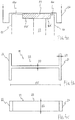
- Fig. 4d illustrate a top view of a wall 1, with the top element removed, constructed by two wall sections 10a, 10b arranged end to end adjacent each other.
- the top connecting element 19 is arranged in openings of both wall sections 10a, 10b.
- the top connecting element 19 is, as described above, an I-shaped element with a first end part 21 and a second end part 22.
- the first end part 21 has a first end portion 21 a arranged in the opening in the wall element of the first wall section 10a and a second end portion 21 b arranged in the opening in the wall element of the second wall section 10b.
- the first end part 21 is arranged at an optional distance from the outside of the wall element.
- the second end part 22 has a first end portion 22a arranged in the opening in the L-element of the first wall section 10a and a second end portion 22b arranged in the opening in the L-element of the second wall section 10b. Also, the second end part 22 is arranged at an optional distance from the outside of the L-element.
- the top connecting element 19 further has an intermediate part 23 extending between the first end part 21 and the second end part 22. With this feature it is preferred to arrange a top connecting element 19 in the boundary between two wall sections 10a, 10b.
- the top connecting element 119 is another possible embodiment, which also is configured to connect the top 11 a of the L-element 11 with the top 16a of the wall element 16.
- the top connecting element 119 has a first end part 121, a second end part 122 and an intermediate part 123 extending between the first end part 121 and the second end part 122.
- the top connecting element 119 has an even thickness X8 of between 2 and 10mm, for example 5mm.
- the first end part 21 is arranged in the opening 16a' in the top 16a of the wall element 16, similar to the previously described embodiment.
- the second end part 122 is instead arranged to hook the top 11 a of the L-element 11. It is of course possible to arrange the top connecting element 119 the other way around so that the first end part 121 is arranged in the opening of the top of the L-element and the second end part is arranged to hook the top of the wall element.
- the second end part 122 includes a first unit 122a integrated with the intermediate part 123.
- the first unit 122a is arranged to extend over the top 11 a of the L-element 11.
- the second end part 122 includes a second unit 122b integrated with the first unit 122a.
- the second unit 122b extends substantially perpendicular to the first unit 122a down along the outer side of the L-element 11.
- the second unit 122b of the second end part 122 should however not extend down more that what the top element 26 covers so that it becomes visible from the outside of the wall 1.
- the first end part 121 may extend down into the wall element 16 as far as necessary, for example between 100 and 300mm.
- Fig. 5c illustrate a top view of a wall 1, with the top element removed, constructed by two wall sections 10a, 10b arranged end to end adjacent each other.
- the top connecting element 119 is, as described above, arranged to connect the two wall sections 10a, 10b.
- the first end part 121 is arranged in the wall elements of the first and second wall section 10a, 10b.
- the second end part 122 is arranged to hook the L-elements if of the first and second wall section 10a, 10b.
- the top connecting element 119 has, as described, an intermediate part 123 extending between the first end part 121 and the second end part 122.
- top connecting element 119 in the boundary between two wall sections 10a, 10b.
- the top connecting element as also described above, may be arranged the other way around such that the first end part is arranged in the L-elements and the second end part is arranged to hook the wall elements.
- the wall section 10 further includes a pre-fabricated top element 26 which is arranged to enclose the top 11 a of the L-element 11 and the top 16a of the wall element 16.
- the top element 26 has a first and a second side portion 26a, 26b which are arranged to extend in a vertical direction down along the extension of the L-element 11 and the wall element 16 respectively. Between an inner surface of the first side portion 26a and the L-element there is preferably a space.
- the space may have a width X3a of between 10 and 15mm, preferably 12mm.
- the space may have a width X3b of between 10 and 15 mm, also preferably 12mm.
- the two spaces are preferred if there is a desire to for example mount a light arrangement or the like as the light arrangement may be arranged within the spaces to create a flowing light from the top of the wall 1 down along respective side.
- the L-element 11, the wall element 16 and the top element 26 define a hollow space 27 inside the wall section 10.
- the hollow space 27 is configured to house cables, pipes, hoses, equipment for a gate, e.g. a motor, or the like and has preferably a width X4 of 30-300mm depending on the use of the wall.
Landscapes
- Engineering & Computer Science (AREA)
- Life Sciences & Earth Sciences (AREA)
- General Life Sciences & Earth Sciences (AREA)
- Mining & Mineral Resources (AREA)
- Paleontology (AREA)
- Civil Engineering (AREA)
- General Engineering & Computer Science (AREA)
- Structural Engineering (AREA)
- Non-Portable Lighting Devices Or Systems Thereof (AREA)
Priority Applications (1)
| Application Number | Priority Date | Filing Date | Title |
|---|---|---|---|
| EP18162276.2A EP3540152A1 (fr) | 2018-03-16 | 2018-03-16 | Section de paroi pour construction d'un mur |
Applications Claiming Priority (1)
| Application Number | Priority Date | Filing Date | Title |
|---|---|---|---|
| EP18162276.2A EP3540152A1 (fr) | 2018-03-16 | 2018-03-16 | Section de paroi pour construction d'un mur |
Publications (1)
| Publication Number | Publication Date |
|---|---|
| EP3540152A1 true EP3540152A1 (fr) | 2019-09-18 |
Family
ID=61692197
Family Applications (1)
| Application Number | Title | Priority Date | Filing Date |
|---|---|---|---|
| EP18162276.2A Withdrawn EP3540152A1 (fr) | 2018-03-16 | 2018-03-16 | Section de paroi pour construction d'un mur |
Country Status (1)
| Country | Link |
|---|---|
| EP (1) | EP3540152A1 (fr) |
Citations (6)
| Publication number | Priority date | Publication date | Assignee | Title |
|---|---|---|---|---|
| DE1908502A1 (de) * | 1969-02-20 | 1970-08-27 | Voss Dipl Ing Reinhard | Einfriedigung aus Beton od.dgl. |
| FR2457928A1 (fr) * | 1979-06-01 | 1980-12-26 | Salviam Brun | Dispositif formant glissiere de securite et support de panneaux |
| GB2267105A (en) * | 1992-05-20 | 1993-11-24 | Albert Seward | A wall structure suitable for, e.g. a barbecue, coal bunker, or garden shed |
| FR2841280A1 (fr) * | 2002-06-24 | 2003-12-26 | Vezenobres Atel | Procede et elements prefrabriques pour la construction d'un mur |
| FR2994702A1 (fr) * | 2012-08-27 | 2014-02-28 | Lauf Maths | Module de paroi laterale, notamment de bassin ou de mur routier ou de cloture, ensemble de tels modules et bassin comportant de tels modules |
| EP3205788A1 (fr) * | 2016-02-09 | 2017-08-16 | G2S Technologies S.A. | Bloc de construction isolé avec l'isolation entre parois externes avec une structure de maintien des parois |
-
2018
- 2018-03-16 EP EP18162276.2A patent/EP3540152A1/fr not_active Withdrawn
Patent Citations (6)
| Publication number | Priority date | Publication date | Assignee | Title |
|---|---|---|---|---|
| DE1908502A1 (de) * | 1969-02-20 | 1970-08-27 | Voss Dipl Ing Reinhard | Einfriedigung aus Beton od.dgl. |
| FR2457928A1 (fr) * | 1979-06-01 | 1980-12-26 | Salviam Brun | Dispositif formant glissiere de securite et support de panneaux |
| GB2267105A (en) * | 1992-05-20 | 1993-11-24 | Albert Seward | A wall structure suitable for, e.g. a barbecue, coal bunker, or garden shed |
| FR2841280A1 (fr) * | 2002-06-24 | 2003-12-26 | Vezenobres Atel | Procede et elements prefrabriques pour la construction d'un mur |
| FR2994702A1 (fr) * | 2012-08-27 | 2014-02-28 | Lauf Maths | Module de paroi laterale, notamment de bassin ou de mur routier ou de cloture, ensemble de tels modules et bassin comportant de tels modules |
| EP3205788A1 (fr) * | 2016-02-09 | 2017-08-16 | G2S Technologies S.A. | Bloc de construction isolé avec l'isolation entre parois externes avec une structure de maintien des parois |
Similar Documents
| Publication | Publication Date | Title |
|---|---|---|
| CA2105787C (fr) | Tuyau de drainage a fente | |
| US9206595B2 (en) | Handmade structure system | |
| US8186127B1 (en) | Basement water drainage method for use with a foundation having no footing | |
| AU757709B2 (en) | Modular element for crawl spaces and floor structures | |
| US5400555A (en) | Modular swimming pool with wall hanging assembly | |
| US20140147210A1 (en) | Prefabricated drain structure | |
| JP2008031824A (ja) | 柵のビーム取付構造 | |
| ES2302741T3 (es) | Procedimiento y sistema para construir losas grandes continuas de hormigon. | |
| KR101220128B1 (ko) | 중공슬래브용 경량체 모듈 | |
| KR100795084B1 (ko) | 주주용 베이스 | |
| US12163335B1 (en) | Drainage junction shield | |
| EP2503078A1 (fr) | Structure de protection, en particulier pour un équipement électrique | |
| KR101323380B1 (ko) | 매립형 고정 브라켓 | |
| ES2644688T3 (es) | Conjunto para la colocación de hormigón, que incluye una guía de enrasado/junta de control | |
| JP3191835U (ja) | 路面用排水溝 | |
| KR101580133B1 (ko) | 한옥의 지붕슬래브 서까래 고정장치 및 그를 이용한 조립식 한옥지붕 | |
| KR20240120194A (ko) | 시공이 쉬운 두겁대 | |
| US20250125604A1 (en) | Precast concrete utility vault | |
| KR101159636B1 (ko) | 유도휀스가 구비된 배수로 | |
| JP2021102886A (ja) | 歩車道境界ブロック | |
| JP7046713B2 (ja) | 給電柱 | |
| JP2021102888A (ja) | 歩車道境界ブロック | |
| KR101696396B1 (ko) | 자연석 옹벽 구조물 | |
| JP4474920B2 (ja) | 人工地盤用壁体及びそれを用いた緑化設備 | |
| KR200344166Y1 (ko) | 상하수도관의 매립설치구조물 |
Legal Events
| Date | Code | Title | Description |
|---|---|---|---|
| PUAI | Public reference made under article 153(3) epc to a published international application that has entered the european phase |
Free format text: ORIGINAL CODE: 0009012 |
|
| AK | Designated contracting states |
Kind code of ref document: A1 Designated state(s): AL AT BE BG CH CY CZ DE DK EE ES FI FR GB GR HR HU IE IS IT LI LT LU LV MC MK MT NL NO PL PT RO RS SE SI SK SM TR |
|
| AX | Request for extension of the european patent |
Extension state: BA ME |
|
| STAA | Information on the status of an ep patent application or granted ep patent |
Free format text: STATUS: THE APPLICATION IS DEEMED TO BE WITHDRAWN |
|
| 18D | Application deemed to be withdrawn |
Effective date: 20200603 |