EP3540251A1 - Zylinderförmiges kugellager - Google Patents
Zylinderförmiges kugellager Download PDFInfo
- Publication number
- EP3540251A1 EP3540251A1 EP17869734.8A EP17869734A EP3540251A1 EP 3540251 A1 EP3540251 A1 EP 3540251A1 EP 17869734 A EP17869734 A EP 17869734A EP 3540251 A1 EP3540251 A1 EP 3540251A1
- Authority
- EP
- European Patent Office
- Prior art keywords
- diameter side
- cylindrical roller
- inner diameter
- roller
- cage
- Prior art date
- Legal status (The legal status is an assumption and is not a legal conclusion. Google has not performed a legal analysis and makes no representation as to the accuracy of the status listed.)
- Withdrawn
Links
- 229920005989 resin Polymers 0.000 claims description 9
- 239000011347 resin Substances 0.000 claims description 9
- 230000000694 effects Effects 0.000 description 8
- 238000012986 modification Methods 0.000 description 8
- 230000004048 modification Effects 0.000 description 8
- 238000000465 moulding Methods 0.000 description 5
- 239000000314 lubricant Substances 0.000 description 3
- 230000001050 lubricating effect Effects 0.000 description 3
- 238000005461 lubrication Methods 0.000 description 3
- 230000002265 prevention Effects 0.000 description 3
- 229910052799 carbon Inorganic materials 0.000 description 2
- 238000001746 injection moulding Methods 0.000 description 2
- 229920003002 synthetic resin Polymers 0.000 description 2
- 239000000057 synthetic resin Substances 0.000 description 2
- 229920000049 Carbon (fiber) Polymers 0.000 description 1
- 239000004696 Poly ether ether ketone Substances 0.000 description 1
- 229930182556 Polyacetal Natural products 0.000 description 1
- 239000004952 Polyamide Substances 0.000 description 1
- 239000004642 Polyimide Substances 0.000 description 1
- 239000004734 Polyphenylene sulfide Substances 0.000 description 1
- 229920006231 aramid fiber Polymers 0.000 description 1
- 230000004323 axial length Effects 0.000 description 1
- 239000004917 carbon fiber Substances 0.000 description 1
- 239000003365 glass fiber Substances 0.000 description 1
- 239000004519 grease Substances 0.000 description 1
- 238000003780 insertion Methods 0.000 description 1
- 230000037431 insertion Effects 0.000 description 1
- 238000009434 installation Methods 0.000 description 1
- 230000001788 irregular Effects 0.000 description 1
- 239000010687 lubricating oil Substances 0.000 description 1
- 239000000463 material Substances 0.000 description 1
- VNWKTOKETHGBQD-UHFFFAOYSA-N methane Chemical compound C VNWKTOKETHGBQD-UHFFFAOYSA-N 0.000 description 1
- 239000003921 oil Substances 0.000 description 1
- 229920002647 polyamide Polymers 0.000 description 1
- 229920002530 polyetherether ketone Polymers 0.000 description 1
- 229920001721 polyimide Polymers 0.000 description 1
- 229920006324 polyoxymethylene Polymers 0.000 description 1
- 229920000069 polyphenylene sulfide Polymers 0.000 description 1
- 239000012779 reinforcing material Substances 0.000 description 1
- 238000005096 rolling process Methods 0.000 description 1
- 239000000243 solution Substances 0.000 description 1
Images


Classifications
-
- F—MECHANICAL ENGINEERING; LIGHTING; HEATING; WEAPONS; BLASTING
- F16—ENGINEERING ELEMENTS AND UNITS; GENERAL MEASURES FOR PRODUCING AND MAINTAINING EFFECTIVE FUNCTIONING OF MACHINES OR INSTALLATIONS; THERMAL INSULATION IN GENERAL
- F16C—SHAFTS; FLEXIBLE SHAFTS; ELEMENTS OR CRANKSHAFT MECHANISMS; ROTARY BODIES OTHER THAN GEARING ELEMENTS; BEARINGS
- F16C19/00—Bearings with rolling contact, for exclusively rotary movement
- F16C19/22—Bearings with rolling contact, for exclusively rotary movement with bearing rollers essentially of the same size in one or more circular rows, e.g. needle bearings
- F16C19/24—Bearings with rolling contact, for exclusively rotary movement with bearing rollers essentially of the same size in one or more circular rows, e.g. needle bearings for radial load mainly
- F16C19/26—Bearings with rolling contact, for exclusively rotary movement with bearing rollers essentially of the same size in one or more circular rows, e.g. needle bearings for radial load mainly with a single row of rollers
-
- F—MECHANICAL ENGINEERING; LIGHTING; HEATING; WEAPONS; BLASTING
- F16—ENGINEERING ELEMENTS AND UNITS; GENERAL MEASURES FOR PRODUCING AND MAINTAINING EFFECTIVE FUNCTIONING OF MACHINES OR INSTALLATIONS; THERMAL INSULATION IN GENERAL
- F16C—SHAFTS; FLEXIBLE SHAFTS; ELEMENTS OR CRANKSHAFT MECHANISMS; ROTARY BODIES OTHER THAN GEARING ELEMENTS; BEARINGS
- F16C33/00—Parts of bearings; Special methods for making bearings or parts thereof
- F16C33/30—Parts of ball or roller bearings
- F16C33/46—Cages for rollers or needles
- F16C33/54—Cages for rollers or needles made from wire, strips, or sheet metal
- F16C33/541—Details of individual pockets, e.g. shape or roller retaining means
-
- F—MECHANICAL ENGINEERING; LIGHTING; HEATING; WEAPONS; BLASTING
- F16—ENGINEERING ELEMENTS AND UNITS; GENERAL MEASURES FOR PRODUCING AND MAINTAINING EFFECTIVE FUNCTIONING OF MACHINES OR INSTALLATIONS; THERMAL INSULATION IN GENERAL
- F16C—SHAFTS; FLEXIBLE SHAFTS; ELEMENTS OR CRANKSHAFT MECHANISMS; ROTARY BODIES OTHER THAN GEARING ELEMENTS; BEARINGS
- F16C33/00—Parts of bearings; Special methods for making bearings or parts thereof
- F16C33/30—Parts of ball or roller bearings
- F16C33/46—Cages for rollers or needles
- F16C33/4617—Massive or moulded cages having cage pockets surrounding the rollers, e.g. machined window cages
- F16C33/4623—Massive or moulded cages having cage pockets surrounding the rollers, e.g. machined window cages formed as one-piece cages, i.e. monoblock cages
- F16C33/4635—Massive or moulded cages having cage pockets surrounding the rollers, e.g. machined window cages formed as one-piece cages, i.e. monoblock cages made from plastic, e.g. injection moulded window cages
-
- F—MECHANICAL ENGINEERING; LIGHTING; HEATING; WEAPONS; BLASTING
- F16—ENGINEERING ELEMENTS AND UNITS; GENERAL MEASURES FOR PRODUCING AND MAINTAINING EFFECTIVE FUNCTIONING OF MACHINES OR INSTALLATIONS; THERMAL INSULATION IN GENERAL
- F16C—SHAFTS; FLEXIBLE SHAFTS; ELEMENTS OR CRANKSHAFT MECHANISMS; ROTARY BODIES OTHER THAN GEARING ELEMENTS; BEARINGS
- F16C33/00—Parts of bearings; Special methods for making bearings or parts thereof
- F16C33/30—Parts of ball or roller bearings
- F16C33/46—Cages for rollers or needles
- F16C33/467—Details of individual pockets, e.g. shape or roller retaining means
- F16C33/4676—Details of individual pockets, e.g. shape or roller retaining means of the stays separating adjacent cage pockets, e.g. guide means for the bearing-surface of the rollers
-
- F—MECHANICAL ENGINEERING; LIGHTING; HEATING; WEAPONS; BLASTING
- F16—ENGINEERING ELEMENTS AND UNITS; GENERAL MEASURES FOR PRODUCING AND MAINTAINING EFFECTIVE FUNCTIONING OF MACHINES OR INSTALLATIONS; THERMAL INSULATION IN GENERAL
- F16C—SHAFTS; FLEXIBLE SHAFTS; ELEMENTS OR CRANKSHAFT MECHANISMS; ROTARY BODIES OTHER THAN GEARING ELEMENTS; BEARINGS
- F16C33/00—Parts of bearings; Special methods for making bearings or parts thereof
- F16C33/30—Parts of ball or roller bearings
- F16C33/46—Cages for rollers or needles
- F16C33/54—Cages for rollers or needles made from wire, strips, or sheet metal
-
- F—MECHANICAL ENGINEERING; LIGHTING; HEATING; WEAPONS; BLASTING
- F16—ENGINEERING ELEMENTS AND UNITS; GENERAL MEASURES FOR PRODUCING AND MAINTAINING EFFECTIVE FUNCTIONING OF MACHINES OR INSTALLATIONS; THERMAL INSULATION IN GENERAL
- F16C—SHAFTS; FLEXIBLE SHAFTS; ELEMENTS OR CRANKSHAFT MECHANISMS; ROTARY BODIES OTHER THAN GEARING ELEMENTS; BEARINGS
- F16C33/00—Parts of bearings; Special methods for making bearings or parts thereof
- F16C33/30—Parts of ball or roller bearings
- F16C33/46—Cages for rollers or needles
- F16C33/56—Selection of substances
-
- F—MECHANICAL ENGINEERING; LIGHTING; HEATING; WEAPONS; BLASTING
- F16—ENGINEERING ELEMENTS AND UNITS; GENERAL MEASURES FOR PRODUCING AND MAINTAINING EFFECTIVE FUNCTIONING OF MACHINES OR INSTALLATIONS; THERMAL INSULATION IN GENERAL
- F16C—SHAFTS; FLEXIBLE SHAFTS; ELEMENTS OR CRANKSHAFT MECHANISMS; ROTARY BODIES OTHER THAN GEARING ELEMENTS; BEARINGS
- F16C2208/00—Plastics; Synthetic resins, e.g. rubbers
- F16C2208/20—Thermoplastic resins
- F16C2208/40—Imides, e.g. polyimide [PI], polyetherimide [PEI]
-
- F—MECHANICAL ENGINEERING; LIGHTING; HEATING; WEAPONS; BLASTING
- F16—ENGINEERING ELEMENTS AND UNITS; GENERAL MEASURES FOR PRODUCING AND MAINTAINING EFFECTIVE FUNCTIONING OF MACHINES OR INSTALLATIONS; THERMAL INSULATION IN GENERAL
- F16C—SHAFTS; FLEXIBLE SHAFTS; ELEMENTS OR CRANKSHAFT MECHANISMS; ROTARY BODIES OTHER THAN GEARING ELEMENTS; BEARINGS
- F16C2208/00—Plastics; Synthetic resins, e.g. rubbers
- F16C2208/20—Thermoplastic resins
- F16C2208/52—Polyphenylene sulphide [PPS]
-
- F—MECHANICAL ENGINEERING; LIGHTING; HEATING; WEAPONS; BLASTING
- F16—ENGINEERING ELEMENTS AND UNITS; GENERAL MEASURES FOR PRODUCING AND MAINTAINING EFFECTIVE FUNCTIONING OF MACHINES OR INSTALLATIONS; THERMAL INSULATION IN GENERAL
- F16C—SHAFTS; FLEXIBLE SHAFTS; ELEMENTS OR CRANKSHAFT MECHANISMS; ROTARY BODIES OTHER THAN GEARING ELEMENTS; BEARINGS
- F16C2208/00—Plastics; Synthetic resins, e.g. rubbers
- F16C2208/20—Thermoplastic resins
- F16C2208/60—Polyamides [PA]
-
- F—MECHANICAL ENGINEERING; LIGHTING; HEATING; WEAPONS; BLASTING
- F16—ENGINEERING ELEMENTS AND UNITS; GENERAL MEASURES FOR PRODUCING AND MAINTAINING EFFECTIVE FUNCTIONING OF MACHINES OR INSTALLATIONS; THERMAL INSULATION IN GENERAL
- F16C—SHAFTS; FLEXIBLE SHAFTS; ELEMENTS OR CRANKSHAFT MECHANISMS; ROTARY BODIES OTHER THAN GEARING ELEMENTS; BEARINGS
- F16C2220/00—Shaping
- F16C2220/02—Shaping by casting
- F16C2220/04—Shaping by casting by injection-moulding
-
- F—MECHANICAL ENGINEERING; LIGHTING; HEATING; WEAPONS; BLASTING
- F16—ENGINEERING ELEMENTS AND UNITS; GENERAL MEASURES FOR PRODUCING AND MAINTAINING EFFECTIVE FUNCTIONING OF MACHINES OR INSTALLATIONS; THERMAL INSULATION IN GENERAL
- F16C—SHAFTS; FLEXIBLE SHAFTS; ELEMENTS OR CRANKSHAFT MECHANISMS; ROTARY BODIES OTHER THAN GEARING ELEMENTS; BEARINGS
- F16C2240/00—Specified values or numerical ranges of parameters; Relations between them
- F16C2240/40—Linear dimensions, e.g. length, radius, thickness, gap
- F16C2240/44—Hole or pocket sizes
-
- F—MECHANICAL ENGINEERING; LIGHTING; HEATING; WEAPONS; BLASTING
- F16—ENGINEERING ELEMENTS AND UNITS; GENERAL MEASURES FOR PRODUCING AND MAINTAINING EFFECTIVE FUNCTIONING OF MACHINES OR INSTALLATIONS; THERMAL INSULATION IN GENERAL
- F16C—SHAFTS; FLEXIBLE SHAFTS; ELEMENTS OR CRANKSHAFT MECHANISMS; ROTARY BODIES OTHER THAN GEARING ELEMENTS; BEARINGS
- F16C2240/00—Specified values or numerical ranges of parameters; Relations between them
- F16C2240/40—Linear dimensions, e.g. length, radius, thickness, gap
- F16C2240/46—Gap sizes or clearances
-
- F—MECHANICAL ENGINEERING; LIGHTING; HEATING; WEAPONS; BLASTING
- F16—ENGINEERING ELEMENTS AND UNITS; GENERAL MEASURES FOR PRODUCING AND MAINTAINING EFFECTIVE FUNCTIONING OF MACHINES OR INSTALLATIONS; THERMAL INSULATION IN GENERAL
- F16C—SHAFTS; FLEXIBLE SHAFTS; ELEMENTS OR CRANKSHAFT MECHANISMS; ROTARY BODIES OTHER THAN GEARING ELEMENTS; BEARINGS
- F16C2240/00—Specified values or numerical ranges of parameters; Relations between them
- F16C2240/40—Linear dimensions, e.g. length, radius, thickness, gap
- F16C2240/70—Diameters; Radii
-
- F—MECHANICAL ENGINEERING; LIGHTING; HEATING; WEAPONS; BLASTING
- F16—ENGINEERING ELEMENTS AND UNITS; GENERAL MEASURES FOR PRODUCING AND MAINTAINING EFFECTIVE FUNCTIONING OF MACHINES OR INSTALLATIONS; THERMAL INSULATION IN GENERAL
- F16C—SHAFTS; FLEXIBLE SHAFTS; ELEMENTS OR CRANKSHAFT MECHANISMS; ROTARY BODIES OTHER THAN GEARING ELEMENTS; BEARINGS
- F16C2322/00—Apparatus used in shaping articles
- F16C2322/39—General buildup of machine tools, e.g. spindles, slides, actuators
Definitions
- the present invention relates to a cylindrical roller bearing, and particularly to a cylindrical roller bearing suitable for a machine tool spindle.
- dmN inner diameter of bearing + outer diameter of bearing
- rpm rotational speed
- an outer diameter restraint type cage is disposed in the cylindrical roller bearing described in Patent Literature 1.
- the cage is made of a synthetic resin and prevents forced drawing upon release of a product from a mold for injection molding during resin cage molding and prevents the roller from biting into column portions of the cage. Since a guide gap expands due to centrifugal expansion and thermal expansion during operation, the outer diameter restraint type cage is suitable for a certain high-speed use condition without excessive contact with the roller.
- the roller during operation is pressed to an outer ring side by centrifugal force, an act from an pocket opening portion (roller guide portion) to an inner ring side is pressed by the outer diameter restraint type cage, irregular movement (in particular, skew movement) of rolling elements caused by the positive radial gap is restricted, and it is effective in suppressing the squeak noise and suppressing the wear between the inner ring flange surface and the end surface.
- the outer diameter restraint type cage as in Patent Document 1 cannot make a roller holding angle smaller than a certain value.
- the roller holding angle is large, the roller easily bites into the column portions of the cage in the wedge shape under high speed conditions, and thus high-speed performance is determined by the roller holding angle.
- the present invention has been made in view of the above-described problems, and an object thereof is to provide a cylindrical roller bearing capable of suppressing generation of squeak noise and wear of a roller end surface and wear of an inner ring flange surface at low speed, and preventing the roller from biting into column portions of the cage in a wedge shape at a high speed.
- the column portions of the cage include roller holding portions which restrain the cylindrical roller on the outer diameter side and the inner diameter side thereof.
- the roller holding portions are formed such that for the radial movement amount of the cage with respect to the cylindrical roller, the outer diameter side movement amount ⁇ the inner diameter side movement amount, and the outer diameter side opening width of the pocket portion > the inner diameter side opening width of the pocket portion from the state where the revolution center of the cylindrical roller coincides with the axial center of the cage, and the column portion includes the inner diameter side protrusion which protrudes further to the inner diameter side than the inner circumferential surfaces of the annular portions and configures the roller holding portions.
- the cylindrical roller is guided on the outer diameter side of the column portion at low speed, the skew of the cylindrical roller is suppressed, and effects of preventing roller end surface wear, inner ring flange surface wear, and squeak noise are obtained. Further, since the cylindrical roller is guided on the inner diameter sides of the column portions having the opening width narrowed by the inner diameter side protrusion by the thermal expansion and the centrifugal expansion of the cage at high speed, the cylindrical roller can be prevented from biting into the column portions of the cage by the roller holding angle on the relatively narrow inner diameter side.
- a cylindrical roller bearing 10 includes an outer ring 11 having an outer ring raceway surface 11a formed on an inner circumferential surface, an inner ring 12 having an inner ring raceway surface 12a formed on an outer circumferential surface, a plurality of cylindrical rollers 13 rollably disposed between the outer ring raceway surface 11a and the inner ring raceway surface 12a, and a roller guide type resin cage 14 forming a plurality of pocket portions 15 which rotatably hold the plurality of cylindrical rollers 13 respectively.
- the inner ring 12 includes flange portions 12b, 12b at both axial end portions of the inner ring raceway surface 12a.
- the cylindrical roller bearing 10 may be lubricated with any lubricant of lubricating oil and grease.
- the resin cage 14 is made of a synthetic resin material such as polyamide, polyacetal, polyether ether ketone, polyimide, and polyphenylene sulfide, and if necessary, a reinforcing material such as a glass fiber, a carbon fiber, and a aramid fiber may be added to the resin.
- a synthetic resin material such as polyamide, polyacetal, polyether ether ketone, polyimide, and polyphenylene sulfide
- a reinforcing material such as a glass fiber, a carbon fiber, and a aramid fiber may be added to the resin.
- the resin cage 14 includes a pair of annular portions 16, 16, and a plurality of column portions 17 axially connecting the pair of annular portions 16, 16.
- An axially intermediate portion 17a of the column portion 17 includes a pair of roller holding portions 18, 18 disposed so as to be spaced apart from each other in an axial direction.
- the pair of roller holding portions 18, 18 has a predetermined axial length and is formed so as to protrude in a circumferential direction more than a side surface of the column portion 17 located therebetween. In this way, the pair of roller holding portions 18, 18 formed by being divided in the axial direction can be elastically deformed upon receiving a force generated by mutual sliding with the cylindrical roller 13, and can release a part of a force received by the column portion 17.
- Inner surfaces of the roller holding portions 18, 18 on the outer diameter side and the inner diameter side protrude circumferentially toward a center of the pocket portions 15, and restrain the cylindrical rollers 13 on the outer diameter side and the inner diameter side thereof.
- the roller holding portions 18, 18 are formed such that a radial movement amount of the cage 14 with respect to the cylindrical roller 13 from a state where a revolution center C1 of the cylindrical roller 13 coincides with an axial center C2 of the cage 14 is configured so that an outer diameter side movement amount is smaller than an inner diameter side movement amount.
- the outer diameter side movement amount and the inner diameter side movement amount from the state where the revolution center C1 of the cylindrical roller 13 coincides with the axial center C2 of the cage 14 respectively correspond to an outer diameter side gap g1 and an inner diameter side gap g2 along a radial direction between the roller holding portion 18 and the cylindrical roller 13 located on a pitch circle diameter PCD. Therefore, in the present embodiment, the inner diameter side gap g2 is designed to be larger than the outer diameter side gap g1.
- the inner surfaces of the roller holding portions 18, 18 are concaved shape with a single curvature radius R which has a center on an inner side with respect to a center O of the cylindrical roller 13 located on the pitch circle diameter PCD. Accordingly, the above relationship between the outer diameter side gap g1 and the inner diameter side gap g2 is given.
- An inner diameter side opening width W2 of the pocket portion 15 is designed to be narrower than an outer diameter side opening width W1 of the pocket portion 15 by the roller holding portions 18, 18 (outer diameter side opening width W1 > inner diameter side opening width W2).
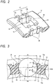
- an axially intermediate portion 17a including the pair of roller holding portions 18, 18 includes an inner diameter side protrusion 30 which protrudes to an inner diameter side than both axial end portions 17b of the column portion 17 located axially outer side than the pair of roller holding portions 18, 18 and the annular portions 16, 16.
- a roller holding angle ⁇ on the inner diameter side can be designed to be smaller than a roller holding angle ⁇ on the outer diameter side.
- the roller holding angle refers to an angle at which line segments connecting contact points where the pair of column portions 17, 17 is brought into contact with the cylindrical roller 13 to the center O of the cylindrical roller 13 intersect when the cage 14 and the cylindrical roller 13 move relatively in the radial direction.
- the cylindrical roller 13 In the cylindrical roller bearing 10 at a low speed, the cylindrical roller 13 is guided on the outer diameter side of the column portion 17, since the skew of the cylindrical roller 13 is suppressed, the wear of a roller end surface, the wear of the inner ring flange surface, and the generation of squeak noise are suppressed. It should be noted that a phenomenon in which the cylindrical roller 13 bites into the column portions 17 in a wedge shape due to a large roller holding angle ⁇ on the outer diameter side is not a problem because the cylindrical roller 13 is in a low speed.
- a contact portion a between the cylindrical roller 13 and each of the roller holding portions 18, 18 is an edge-contact.
- the cage 14 is relatively expanded by thermal expansion and centrifugal expansion, so that the cylindrical roller 13 is guided on an inner diameter side of the column portion 17 having a narrow opening width. Accordingly, inner surfaces on the outer diameter side of the roller holding portions 18, 18 serve as non-guiding surfaces.
- the relatively small roller holding angle ⁇ on the inner diameter side can prevent the cylindrical roller 13 from biting into the column portions 17 of the cage 14 in a wedge shape on the inner surfaces on the inner diameter side.
- a contact portion b between the cylindrical roller 13 and each of the roller bearing portions 18, 18 is an edge-contact.
- An inner diameter ⁇ Di of the inner diameter side protrusion 30 is preferably smaller in order to reduce the roller holding angle ⁇ .
- an inner diameter of the cage 14, that is, an inner diameter ⁇ Di of the inner diameter side protrusion 30 is designed to be larger than an outer diameter ⁇ Bo of the flange portion 12b of the inner ring 12 ⁇ B ⁇ ⁇ ⁇ Di).
- sums A + L and B + L of respective distances A and B from both axial end surfaces of the pocket portion 15 to the inner diameter side protrusion 30 and a width L of the inner diameter side protrusion 30 are designed to be shorter than an axial width C of the cylindrical roller 13 (A + L ⁇ C and B + L ⁇ C). Accordingly, a contact between the inner diameter side protrusion 30 and the flange surface of the inner ring 12 is prevented.
- the inner diameter side of the column portion 17 of the cage 14 is not forcibly drawn out at the time of molding, and does not interfere with roller insertion at the time of bearing assembly.
- each mold member for forming each pocket is radially extracted toward a radial direction outer side at the time of mold releasing after molding (so-called radial draw type). Therefore, an inner diameter side of the roller holding portion 18 protruding toward a pocket center side is not forcibly drawn out.
- the cylindrical roller 13 is inserted into the pocket portions 15 of the cage 14, since the cylindrical roller 13 is inserted into the pocket portions 15 from an outer diameter side opening portion, similarly, the inner diameter side of the roller holding portion 18 is not relevant.
- the column portion 17 of the cage 14 includes roller holding portions 18, 18 which restrain the cylindrical roller 13 on the outer diameter side and the inner diameter side thereof.
- the roller holding portions 18, 18 are formed such that the radial movement amount of the cage 14 with respect to the cylindrical roller 13 from the state where the revolution center C1 of the cylindrical roller 13 coincides with the axial center C2 of the cage 14 is configured so that the outer diameter side movement amount ⁇ the inner diameter side movement amount, and the outer diameter side opening width W1 of the pocket portion 15 > the inner diameter side opening width W2 of the pocket portion 15.
- the column portion 17 includes the inner diameter side protrusion 30 which protrudes further to the inner diameter side than the inner circumferential surfaces of the annular portions 16, 16 and configures the roller holding portions 18, 18. Accordingly, at low speed, the cylindrical roller 13 is guided on the outer diameter side of the column portion 17, the skew of the cylindrical roller 13 is suppressed, and effects of roller end surface wear prevention, inner ring flange surface wear prevention, and squeak noise prevention are obtained. Further, at high speed, since the cylindrical roller 13 is guided on the inner diameter sides of the column portions 17 having the opening width W2 narrowed by the thermal expansion and the centrifugal expansion, the roller holding angle ⁇ on the relatively narrow inner diameter side can prevent the cylindrical roller 13 from biting into the column portions 17 of the cage 14.
- FIG. 5 is a cross-sectional view showing a cylindrical roller and a cage in a cylindrical roller bearing according to the second embodiment.
- the shape of the inner surface 19 of each of the roller holding portions 18, 18 is different from that of the first embodiment.
- the inner surface 19 of each of the roller holding portions 18, 18 includes a flat surface 19a passing through the pitch circle diameter PCD position of the cylindrical roller 13 and concave circular arc surfaces 19b, 19c formed on the outer diameter side and the inner diameter side of the flat surface 19a.
- the circular arc surface 19b on the outer diameter side is concaved shape with a curvature radius R1 which has a center on the inner side with respect to the center O of the cylindrical roller 13 located on the pitch circle diameter PCD.
- the circular arc surface 19C on the inner diameter side is concaved shape with a curvature radius R2 which has a center on the outer side with respect to the center O of the cylindrical roller 13 located on the pitch circle diameter PCD.
- the curvature radius R2 of the circular arc surface 19c on the inner diameter side is larger than the curvature radius R1 of the circular arc surface 19b on the outer diameter side. Accordingly, a lubricating reservoir 20 is formed in the vicinity of a connecting portion between the flat surface 19a and the circular arc surface 19c, and the effect of improving the lubrication life is obtained.
- the second embodiment where in the roller holding portions 18, 18 have the above inner surfaces 19 is the same as the first embodiment in that (i) the radial movement amount of the cage 14 with respect to the cylindrical roller 13 from the state where the revolution center C1 of the cylindrical roller 13 coincides with the axial center C2 of the cage 14 is configured so that the outer diameter side movement amount ⁇ the inner diameter side movement amount, and the outer diameter side opening width W1 of the pocket portion 15 > the inner diameter side opening width W2 of the pocket portion 15, and (ii) the column portion 17 includes the inner diameter side protrusion 30 which protrudes to the inner diameter side than the inner circumferential surfaces of the annular portions 16, 16 and the column portion 17 configures the roller holding portions 18, 18.
- the same effects as the first embodiment can be obtained in the second embodiment.
- FIG. 6 is a cross-sectional view showing a cylindrical roller and a cage in a cylindrical roller bearing according to the third embodiment.
- the shape of the inner surface 19 of each of the roller holding portions 18, 18 is different from that of the first embodiment.
- the inner surface 19 of each of the roller holding portions 18, 18 includes the flat surface 19a passing through the pitch circle diameter PCD position of the cylindrical roller 13, a concave circular arc surfaces 19b formed on the outer diameter side of the flat surface 19a, and a tapered surface 19d formed on the inner diameter side of the flat surface 19a.
- the circular arc surface 19b on the outer diameter side is concave shape with the curvature radius R1 which has center on the inner side with respect to the center O of the cylindrical roller 13 located on the pitch circle diameter PCD.
- the tapered surface 19d on the inner diameter side is inclined toward the center of the pocket portion 15 with respect to the flat surface 19a. Accordingly, in the present embodiment, the lubricating reservoir 20 is also formed in the vicinity of a connecting portion between the flat surface 19a and the tapered surface 19d, and the effect of improving the lubrication life is obtained.
- a tapered angle ⁇ of the tapered surface 19d with respect to the flat surface 19a may be adjusted to be smaller than an angle ⁇ 1 (see FIG. 7A ) at which the tapered surface 19d is edge-contacted with the cylindrical roller 13 and larger than an angle ⁇ 3 (see FIG. 7C ) at which the cylindrical roller 13 bites into the column portion 17.
- the tapered angle ⁇ corresponds to a roller holding angle ⁇ on the inner diameter side, and as shown in FIGS. 7A to 7C , when the tapered angle is ⁇ 1> ⁇ 2> ⁇ 3, the roller holding angle ⁇ is ⁇ 1 ⁇ p2 ⁇ p3.
- the third embodiment where in the roller holding portions 18, 18 have the above inner surfaces 19 is the same as the first embodiment in that (i) the radial movement amount of the cage 14 with respect to the cylindrical roller 13 from the state where the revolution center C1 of the cylindrical roller 13 coincides with the axial center C2 of the cage 14 is configured so that the outer diameter side movement amount ⁇ the inner diameter side movement amount, and the outer diameter side opening width W1 of the pocket portion 15 > the inner diameter side opening width W2 of the pocket portion 15, and (ii) the column portion 17 includes the inner diameter side protrusion 30 which protrudes to the inner diameter side than the inner circumferential surfaces of the annular portions 16, 16 and the column portion 17 configures the roller holding portions 18, 18.
- the same effects as the first embodiment can be obtained in the third embodiment.
- the present invention is not limited to the above-described embodiment and may be appropriately modified, improved, or the like.
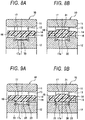
- the shape of the axially intermediate portion 17a of the column portion 17 is deformable as shown in FIGS. 8 to 10 .
- the axially intermediate portion 17a of the column portion 17 may only include the inner diameter side protrusion 30, and as shown in FIG. 8B , the axially intermediate portion 17a of the column portion 17 may include the inner diameter side protrusion 30 and an outer diameter side protrusion 31 protruding to the outer diameter side.
- both axial end surfaces of the inner diameter side protrusion 30 may be tapered surfaces 33, 33, and thus stress concentration of the force acting on the inner diameter side protrusion 30 can be relaxed, and the oil supply and discharge property of the lubricant can be improved.
- the inner diameter side protrusion 30 protruding toward the inner diameter side may be formed to be spaced apart in the axial direction
- both of the inner diameter side and outer diameter side protrusions 30, 31 protruding toward the inner diameter side and the outer diameter side may be formed spaced apart from each other in the axial direction.
- a relief portion 32 formed between the plurality of axially separated protrusions 30, 30 on the inner diameter side holds the lubricant in the circumferential direction of the column portion 17 and contributes to lubricity.
- the strength of the cage 14 may be increased by increasing the radial thickness of the annular portions 16, 16.
- the outer circumferential surfaces of the annular portions 16, 16 may be larger than the outer diameter of the column portion 17 (roller holding portion 18), and in the case of the modification shown in FIG. 11B , the outer circumferential surfaces of the annular portions 16, 16 may be larger than the outer diameter of the outer diameter side projection 31 (roller holding portion 18). Accordingly, it is possible to increase the strength of the annular portions 16, 16 while ensuring the proper opening width of the cylindrical roller 13.
- each of the both axial end portions of the column portion 17 includes an inclined surface 17c which connects an outer circumferential surface of the column portion 17 to each of the outer circumferential surfaces of the annular portions 16, 16, and the strength of the column portion 17 can also be increased by increasing the thickness of the column portion 17 by the inclined surfaces 17c.
- the present invention is not limited to a single-row cylindrical roller bearing, and may be applied to a double-row cylindrical roller bearing as shown in FIG. 12 .
Landscapes
- Engineering & Computer Science (AREA)
- General Engineering & Computer Science (AREA)
- Mechanical Engineering (AREA)
- Rolling Contact Bearings (AREA)
Applications Claiming Priority (2)
| Application Number | Priority Date | Filing Date | Title |
|---|---|---|---|
| JP2016221736A JP2018080718A (ja) | 2016-11-14 | 2016-11-14 | 円筒ころ軸受 |
| PCT/JP2017/040976 WO2018088571A1 (ja) | 2016-11-14 | 2017-11-14 | 円筒ころ軸受 |
Publications (2)
| Publication Number | Publication Date |
|---|---|
| EP3540251A1 true EP3540251A1 (de) | 2019-09-18 |
| EP3540251A4 EP3540251A4 (de) | 2019-11-27 |
Family
ID=62109251
Family Applications (1)
| Application Number | Title | Priority Date | Filing Date |
|---|---|---|---|
| EP17869734.8A Withdrawn EP3540251A4 (de) | 2016-11-14 | 2017-11-14 | Zylinderförmiges kugellager |
Country Status (7)
| Country | Link |
|---|---|
| US (1) | US10605303B2 (de) |
| EP (1) | EP3540251A4 (de) |
| JP (1) | JP2018080718A (de) |
| KR (1) | KR20190057147A (de) |
| CN (1) | CN109923322A (de) |
| TW (1) | TW201817991A (de) |
| WO (1) | WO2018088571A1 (de) |
Cited By (1)
| Publication number | Priority date | Publication date | Assignee | Title |
|---|---|---|---|---|
| EP4269830A1 (de) * | 2022-04-25 | 2023-11-01 | Ringspann GmbH | Käfigfreilauf mit klemmstücken und lagerrollen |
Families Citing this family (7)
| Publication number | Priority date | Publication date | Assignee | Title |
|---|---|---|---|---|
| JP6504299B1 (ja) | 2017-12-07 | 2019-04-24 | 東洋インキScホールディングス株式会社 | 黒色低反射膜、および積層体の製造方法 |
| CN110748560A (zh) * | 2019-11-20 | 2020-02-04 | 上海莱必泰数控机床股份有限公司 | 滚柱直线导轨用钢制链式滚柱保持架 |
| JP7472544B2 (ja) * | 2020-02-28 | 2024-04-23 | 日本精工株式会社 | 外輪付き円筒ころ軸受 |
| CN111765171A (zh) * | 2020-07-16 | 2020-10-13 | 河南科技大学 | 一种圆柱滚子轴承及其保持架 |
| EP4291792B1 (de) | 2021-04-16 | 2024-05-08 | The Timken Company | Schränkwinkelbegrenzender lagerkäfig |
| WO2024018524A1 (ja) * | 2022-07-19 | 2024-01-25 | 株式会社ジェイテクト | ころ軸受 |
| CN116044906A (zh) * | 2022-09-30 | 2023-05-02 | 上海奥德玛机电科技有限公司 | 短圆柱滚子轴承用保持架及短圆柱滚子轴承 |
Family Cites Families (18)
| Publication number | Priority date | Publication date | Assignee | Title |
|---|---|---|---|---|
| US4208078A (en) * | 1977-08-29 | 1980-06-17 | Koyo Seiko Company Limited | Cylindrical roller bearings |
| JPS5514827Y2 (de) * | 1977-12-26 | 1980-04-04 | ||
| DE19531905B4 (de) * | 1995-08-30 | 2004-11-18 | Skf Gmbh | Bord- oder laufbahngeführter Kunststoffkäfig |
| JPH09291942A (ja) * | 1996-02-26 | 1997-11-11 | Nippon Seiko Kk | ラジアル転がり軸受 |
| US6715927B1 (en) | 1999-03-19 | 2004-04-06 | Ntn Corporation | Rolling bearing and bearing apparatus |
| JP2000274437A (ja) | 1999-03-19 | 2000-10-03 | Ntn Corp | 転がり軸受 |
| JP2005069282A (ja) | 2003-08-20 | 2005-03-17 | Ntn Corp | 円筒ころ軸受 |
| JP2006144984A (ja) * | 2004-11-24 | 2006-06-08 | Nsk Ltd | 転がり軸受ユニット |
| JP2006242284A (ja) * | 2005-03-03 | 2006-09-14 | Nsk Ltd | 鍔付円筒ころ軸受 |
| JP2009097525A (ja) * | 2007-10-12 | 2009-05-07 | Nsk Ltd | 保持器付き転がり軸受 |
| JP5749924B2 (ja) * | 2010-12-07 | 2015-07-15 | Ntn株式会社 | 保持器付き針状ころ軸受 |
| JP6422625B2 (ja) * | 2012-03-23 | 2018-11-14 | Ntn株式会社 | 針状ころ軸受の保持器および針状ころ軸受構造 |
| EP2865910A4 (de) | 2012-06-21 | 2016-06-08 | Nsk Ltd | Wälzlage und spindelvorrichtung für werkzeugmaschine |
| JP2014159840A (ja) * | 2013-02-20 | 2014-09-04 | Nsk Ltd | ころがり軸受 |
| JP2014169746A (ja) * | 2013-03-04 | 2014-09-18 | Ntn Corp | 転がり軸受 |
| CN204312547U (zh) * | 2014-11-06 | 2015-05-06 | 西北轴承股份有限公司 | 新型圆柱滚子轴承整体保持架 |
| JP2016221736A (ja) | 2015-05-28 | 2016-12-28 | Daisen株式会社 | 表面に静電植毛加工が施された発泡成形製品とその製造方法 |
| CN204878336U (zh) * | 2015-05-31 | 2015-12-16 | 德清恒富机械有限公司 | 单列滚子轴承的保持架组件 |
-
2016
- 2016-11-14 JP JP2016221736A patent/JP2018080718A/ja active Pending
-
2017
- 2017-10-25 TW TW106136701A patent/TW201817991A/zh unknown
- 2017-11-14 KR KR1020197013219A patent/KR20190057147A/ko not_active Ceased
- 2017-11-14 WO PCT/JP2017/040976 patent/WO2018088571A1/ja not_active Ceased
- 2017-11-14 EP EP17869734.8A patent/EP3540251A4/de not_active Withdrawn
- 2017-11-14 CN CN201780069883.3A patent/CN109923322A/zh active Pending
- 2017-11-14 US US16/346,262 patent/US10605303B2/en active Active
Cited By (3)
| Publication number | Priority date | Publication date | Assignee | Title |
|---|---|---|---|---|
| EP4269830A1 (de) * | 2022-04-25 | 2023-11-01 | Ringspann GmbH | Käfigfreilauf mit klemmstücken und lagerrollen |
| US11859677B2 (en) | 2022-04-25 | 2024-01-02 | Ringspann Gmbh | Cage freewheel with bearing rollers |
| EP4269830B1 (de) | 2022-04-25 | 2025-07-02 | Ringspann GmbH | Käfigfreilauf mit klemmstücken und lagerrollen |
Also Published As
| Publication number | Publication date |
|---|---|
| WO2018088571A1 (ja) | 2018-05-17 |
| US10605303B2 (en) | 2020-03-31 |
| TW201817991A (zh) | 2018-05-16 |
| KR20190057147A (ko) | 2019-05-27 |
| CN109923322A (zh) | 2019-06-21 |
| JP2018080718A (ja) | 2018-05-24 |
| EP3540251A4 (de) | 2019-11-27 |
| US20190257354A1 (en) | 2019-08-22 |
Similar Documents
| Publication | Publication Date | Title |
|---|---|---|
| US10605303B2 (en) | Cylindrical roller bearing | |
| US8944693B2 (en) | Rolling bearing cage and rolling bearing | |
| US8939649B2 (en) | Rolling bearing | |
| JP5012498B2 (ja) | 深溝玉軸受 | |
| EP3543553B1 (de) | Wälzlagerkäfig und wälzlager | |
| JP6507764B2 (ja) | 円すいころ軸受 | |
| US20080285904A1 (en) | Cage for rolling bearing and rolling bearing having the same | |
| CN107435685A (zh) | 滚珠轴承 | |
| JP2006022891A (ja) | 玉軸受用保持器 | |
| US10247234B2 (en) | Bearing | |
| US11248656B2 (en) | Cage and roller assembly | |
| US10180161B2 (en) | Tapered roller bearing | |
| US7891881B2 (en) | Drawn cup roller bearing | |
| US10655678B2 (en) | Cage and roller assembly | |
| JPH1151061A (ja) | ころ軸受用合成樹脂製保持器 | |
| US20150369289A1 (en) | Tapered roller bearing | |
| JP2009275759A (ja) | 深溝玉軸受 | |
| JP2009275722A (ja) | 転がり軸受 | |
| US10634191B2 (en) | Cage and roller assembly | |
| JP4537920B2 (ja) | 樹脂保持器並びに樹脂保持器金型および樹脂保持器の製造方法 | |
| US20190368542A1 (en) | Needle roller thrust bearing | |
| EP3540250A1 (de) | Harzhalter für zylindrische wälzlager und wälzlager | |
| US9091300B2 (en) | Rolling-element bearing | |
| JP2007100909A (ja) | ころ軸受 | |
| US20260016049A1 (en) | Ball bearing with an outer ring-guided cage and an eccentric rotation device |
Legal Events
| Date | Code | Title | Description |
|---|---|---|---|
| PUAI | Public reference made under article 153(3) epc to a published international application that has entered the european phase |
Free format text: ORIGINAL CODE: 0009012 |
|
| 17P | Request for examination filed |
Effective date: 20190507 |
|
| AK | Designated contracting states |
Kind code of ref document: A1 Designated state(s): AL AT BE BG CH CY CZ DE DK EE ES FI FR GB GR HR HU IE IS IT LI LT LU LV MC MK MT NL NO PL PT RO RS SE SI SK SM TR |
|
| AX | Request for extension of the european patent |
Extension state: BA ME |
|
| A4 | Supplementary search report drawn up and despatched |
Effective date: 20191025 |
|
| RIC1 | Information provided on ipc code assigned before grant |
Ipc: F16C 33/54 20060101AFI20191021BHEP Ipc: F16C 33/46 20060101ALI20191021BHEP Ipc: F16C 19/26 20060101ALI20191021BHEP |
|
| DAV | Request for validation of the european patent (deleted) | ||
| DAX | Request for extension of the european patent (deleted) | ||
| STAA | Information on the status of an ep patent application or granted ep patent |
Free format text: STATUS: THE APPLICATION IS DEEMED TO BE WITHDRAWN |
|
| 18D | Application deemed to be withdrawn |
Effective date: 20200603 |