EP3540822A1 - Batteriemodul sowie batteriepack und automobil damit - Google Patents
Batteriemodul sowie batteriepack und automobil damit Download PDFInfo
- Publication number
- EP3540822A1 EP3540822A1 EP18806512.2A EP18806512A EP3540822A1 EP 3540822 A1 EP3540822 A1 EP 3540822A1 EP 18806512 A EP18806512 A EP 18806512A EP 3540822 A1 EP3540822 A1 EP 3540822A1
- Authority
- EP
- European Patent Office
- Prior art keywords
- busbar
- battery module
- short
- module according
- battery
- Prior art date
- Legal status (The legal status is an assumption and is not a legal conclusion. Google has not performed a legal analysis and makes no representation as to the accuracy of the status listed.)
- Granted
Links
Images




Classifications
-
- H—ELECTRICITY
- H01—ELECTRIC ELEMENTS
- H01M—PROCESSES OR MEANS, e.g. BATTERIES, FOR THE DIRECT CONVERSION OF CHEMICAL ENERGY INTO ELECTRICAL ENERGY
- H01M10/00—Secondary cells; Manufacture thereof
- H01M10/05—Accumulators with non-aqueous electrolyte
- H01M10/052—Li-accumulators
- H01M10/0525—Rocking-chair batteries, i.e. batteries with lithium insertion or intercalation in both electrodes; Lithium-ion batteries
-
- H—ELECTRICITY
- H01—ELECTRIC ELEMENTS
- H01M—PROCESSES OR MEANS, e.g. BATTERIES, FOR THE DIRECT CONVERSION OF CHEMICAL ENERGY INTO ELECTRICAL ENERGY
- H01M50/00—Constructional details or processes of manufacture of the non-active parts of electrochemical cells other than fuel cells, e.g. hybrid cells
- H01M50/50—Current conducting connections for cells or batteries
- H01M50/572—Means for preventing undesired use or discharge
- H01M50/574—Devices or arrangements for the interruption of current
- H01M50/578—Devices or arrangements for the interruption of current in response to pressure
-
- H—ELECTRICITY
- H01—ELECTRIC ELEMENTS
- H01M—PROCESSES OR MEANS, e.g. BATTERIES, FOR THE DIRECT CONVERSION OF CHEMICAL ENERGY INTO ELECTRICAL ENERGY
- H01M10/00—Secondary cells; Manufacture thereof
- H01M10/42—Methods or arrangements for servicing or maintenance of secondary cells or secondary half-cells
-
- H—ELECTRICITY
- H01—ELECTRIC ELEMENTS
- H01M—PROCESSES OR MEANS, e.g. BATTERIES, FOR THE DIRECT CONVERSION OF CHEMICAL ENERGY INTO ELECTRICAL ENERGY
- H01M50/00—Constructional details or processes of manufacture of the non-active parts of electrochemical cells other than fuel cells, e.g. hybrid cells
- H01M50/20—Mountings; Secondary casings or frames; Racks, modules or packs; Suspension devices; Shock absorbers; Transport or carrying devices; Holders
- H01M50/204—Racks, modules or packs for multiple batteries or multiple cells
- H01M50/207—Racks, modules or packs for multiple batteries or multiple cells characterised by their shape
- H01M50/211—Racks, modules or packs for multiple batteries or multiple cells characterised by their shape adapted for pouch cells
-
- H—ELECTRICITY
- H01—ELECTRIC ELEMENTS
- H01M—PROCESSES OR MEANS, e.g. BATTERIES, FOR THE DIRECT CONVERSION OF CHEMICAL ENERGY INTO ELECTRICAL ENERGY
- H01M50/00—Constructional details or processes of manufacture of the non-active parts of electrochemical cells other than fuel cells, e.g. hybrid cells
- H01M50/50—Current conducting connections for cells or batteries
-
- H—ELECTRICITY
- H01—ELECTRIC ELEMENTS
- H01M—PROCESSES OR MEANS, e.g. BATTERIES, FOR THE DIRECT CONVERSION OF CHEMICAL ENERGY INTO ELECTRICAL ENERGY
- H01M50/00—Constructional details or processes of manufacture of the non-active parts of electrochemical cells other than fuel cells, e.g. hybrid cells
- H01M50/50—Current conducting connections for cells or batteries
- H01M50/502—Interconnectors for connecting terminals of adjacent batteries; Interconnectors for connecting cells outside a battery casing
- H01M50/503—Interconnectors for connecting terminals of adjacent batteries; Interconnectors for connecting cells outside a battery casing characterised by the shape of the interconnectors
-
- H—ELECTRICITY
- H01—ELECTRIC ELEMENTS
- H01M—PROCESSES OR MEANS, e.g. BATTERIES, FOR THE DIRECT CONVERSION OF CHEMICAL ENERGY INTO ELECTRICAL ENERGY
- H01M50/00—Constructional details or processes of manufacture of the non-active parts of electrochemical cells other than fuel cells, e.g. hybrid cells
- H01M50/50—Current conducting connections for cells or batteries
- H01M50/502—Interconnectors for connecting terminals of adjacent batteries; Interconnectors for connecting cells outside a battery casing
- H01M50/507—Interconnectors for connecting terminals of adjacent batteries; Interconnectors for connecting cells outside a battery casing comprising an arrangement of two or more busbars within a container structure, e.g. busbar modules
-
- H—ELECTRICITY
- H01—ELECTRIC ELEMENTS
- H01M—PROCESSES OR MEANS, e.g. BATTERIES, FOR THE DIRECT CONVERSION OF CHEMICAL ENERGY INTO ELECTRICAL ENERGY
- H01M50/00—Constructional details or processes of manufacture of the non-active parts of electrochemical cells other than fuel cells, e.g. hybrid cells
- H01M50/50—Current conducting connections for cells or batteries
- H01M50/502—Interconnectors for connecting terminals of adjacent batteries; Interconnectors for connecting cells outside a battery casing
- H01M50/514—Methods for interconnecting adjacent batteries or cells
-
- H—ELECTRICITY
- H01—ELECTRIC ELEMENTS
- H01M—PROCESSES OR MEANS, e.g. BATTERIES, FOR THE DIRECT CONVERSION OF CHEMICAL ENERGY INTO ELECTRICAL ENERGY
- H01M50/00—Constructional details or processes of manufacture of the non-active parts of electrochemical cells other than fuel cells, e.g. hybrid cells
- H01M50/50—Current conducting connections for cells or batteries
- H01M50/531—Electrode connections inside a battery casing
-
- H—ELECTRICITY
- H01—ELECTRIC ELEMENTS
- H01M—PROCESSES OR MEANS, e.g. BATTERIES, FOR THE DIRECT CONVERSION OF CHEMICAL ENERGY INTO ELECTRICAL ENERGY
- H01M50/00—Constructional details or processes of manufacture of the non-active parts of electrochemical cells other than fuel cells, e.g. hybrid cells
- H01M50/50—Current conducting connections for cells or batteries
- H01M50/543—Terminals
- H01M50/547—Terminals characterised by the disposition of the terminals on the cells
- H01M50/548—Terminals characterised by the disposition of the terminals on the cells on opposite sides of the cell
-
- H—ELECTRICITY
- H01—ELECTRIC ELEMENTS
- H01M—PROCESSES OR MEANS, e.g. BATTERIES, FOR THE DIRECT CONVERSION OF CHEMICAL ENERGY INTO ELECTRICAL ENERGY
- H01M50/00—Constructional details or processes of manufacture of the non-active parts of electrochemical cells other than fuel cells, e.g. hybrid cells
- H01M50/50—Current conducting connections for cells or batteries
- H01M50/543—Terminals
- H01M50/552—Terminals characterised by their shape
- H01M50/553—Terminals adapted for prismatic, pouch or rectangular cells
-
- H—ELECTRICITY
- H01—ELECTRIC ELEMENTS
- H01M—PROCESSES OR MEANS, e.g. BATTERIES, FOR THE DIRECT CONVERSION OF CHEMICAL ENERGY INTO ELECTRICAL ENERGY
- H01M50/00—Constructional details or processes of manufacture of the non-active parts of electrochemical cells other than fuel cells, e.g. hybrid cells
- H01M50/50—Current conducting connections for cells or batteries
- H01M50/572—Means for preventing undesired use or discharge
- H01M50/574—Devices or arrangements for the interruption of current
-
- H—ELECTRICITY
- H01—ELECTRIC ELEMENTS
- H01M—PROCESSES OR MEANS, e.g. BATTERIES, FOR THE DIRECT CONVERSION OF CHEMICAL ENERGY INTO ELECTRICAL ENERGY
- H01M2200/00—Safety devices for primary or secondary batteries
- H01M2200/20—Pressure-sensitive devices
-
- H—ELECTRICITY
- H01—ELECTRIC ELEMENTS
- H01M—PROCESSES OR MEANS, e.g. BATTERIES, FOR THE DIRECT CONVERSION OF CHEMICAL ENERGY INTO ELECTRICAL ENERGY
- H01M2220/00—Batteries for particular applications
- H01M2220/20—Batteries in motive systems, e.g. vehicle, ship, plane
-
- Y—GENERAL TAGGING OF NEW TECHNOLOGICAL DEVELOPMENTS; GENERAL TAGGING OF CROSS-SECTIONAL TECHNOLOGIES SPANNING OVER SEVERAL SECTIONS OF THE IPC; TECHNICAL SUBJECTS COVERED BY FORMER USPC CROSS-REFERENCE ART COLLECTIONS [XRACs] AND DIGESTS
- Y02—TECHNOLOGIES OR APPLICATIONS FOR MITIGATION OR ADAPTATION AGAINST CLIMATE CHANGE
- Y02E—REDUCTION OF GREENHOUSE GAS [GHG] EMISSIONS, RELATED TO ENERGY GENERATION, TRANSMISSION OR DISTRIBUTION
- Y02E60/00—Enabling technologies; Technologies with a potential or indirect contribution to GHG emissions mitigation
- Y02E60/10—Energy storage using batteries
Definitions
- the present disclosure relates to a battery module and a battery pack and a vehicle comprising the same, and more particularly, to a battery module for preventing the overcharge of the battery module and improving stability and a battery pack and a vehicle comprising the same.
- a lithium secondary battery usually uses a lithium-based oxide and a carbon material for a positive electrode active material and a negative electrode active material respectively.
- the lithium secondary battery includes an electrode assembly including a positive electrode plate and a negative electrode plate respectively coated with the positive electrode active material and the negative electrode active material with a separator interposed between, and a packaging or a battery case to hermetically receive the electrode assembly together with an electrolyte solution.
- lithium secondary batteries may be classified into can-type secondary batteries in which an electrode assembly is embedded in a metal can and pouch-type secondary batteries in which an electrode assembly is embedded in a pouch of an aluminum laminate sheet according to the shape of the case.
- the battery pack of hybrid electric vehicles or electric vehicles includes a plurality of secondary batteries, and the plurality of secondary batteries is connected in series and in parallel to improve the capacity and output.
- a secondary battery has good electrical properties, but decomposition reactions of the components of the battery, an active material and an electrolyte take place under abnormal working conditions, for example, overcharge, overdischarge, high temperature exposure and electrical short, producing heat and gas, and as a result, there is a problem with expansion of the secondary battery, a so-called swelling phenomenon.
- the swelling phenomenon accelerates the decomposition reactions, causing explosions and fires of the secondary battery by thermal runaway phenomenon.
- the secondary battery has a safety system, for example, a protection circuit that interrupts an electric current in the event of overcharge, overdischarge and overcurrent, a Positive Temperature Coefficient (PTC) Element having a sharp increase in resistance as a function of the rising temperature to interrupt an electric current, and a safety vent that interrupts an electric current or discharges gas when the pressure increases by the produced gas.
- a safety system for example, a protection circuit that interrupts an electric current in the event of overcharge, overdischarge and overcurrent, a Positive Temperature Coefficient (PTC) Element having a sharp increase in resistance as a function of the rising temperature to interrupt an electric current, and a safety vent that interrupts an electric current or discharges gas when the pressure increases by the produced gas.
- PTC Positive Temperature Coefficient
- the secondary battery repeats predefined expansion and contraction not only in abnormal working condition but also in normal working condition, the secondary battery may be short-circuited by a normal range of expansion, and thus there is a problem with operation reliability.
- the present disclosure is directed to providing a battery module in which a first busbar and a second busbar move toward each other and are brought into contact by the application of an expansion force caused by volume increase of a first battery cell, so that the first busbar and the second busbar are electrically connected to each other, causing a short, and a blow part formed in the first busbar is blown, thereby preventing the overcharge of the battery module, and a battery pack and a vehicle comprising the same.
- a battery module includes a first busbar electrically connected to a first electrode lead of a first battery cell, a second busbar electrically connected to a second electrode lead of a second battery cell, a short part which moves to the first busbar and the second busbar and comes into contact with the first busbar and the second busbar by the application of an expansion force caused by volume increase of the first battery cell to electrically connect the first busbar to the second busbar, causing a short, and a cartridge which receives or supports at least part of the first electrode lead, the second electrode lead, the first busbar, the second busbar and the short part.
- the short part may include an elastic member which provides an elastic force facing the first busbar and the second busbar, and a slide bar which keeps the elastic member in deformed state by latch coupling of a latching part protruding at one end to produce the elastic force and a latching hole of the cartridge.
- the slide bar may restore the deformed state of the elastic member when the latch coupling of the latching part and the latching hole is released by the application of the expansion force to the latching part, and move the first busbar and the second busbar and come into contact with the first busbar and the second busbar by the elastic force applied from the elastic member restored from the deformed state.
- the slide bar may have, at the other end, a short terminal which comes into contact with the first busbar and the second busbar to electrically short the first busbar and the second busbar.
- the short terminal may be formed from a conductive material.
- the cartridge may have a receiving space of a shape corresponding to a shape of the short part to receive the short part therein.
- the receiving space may be formed to fit a volume of the elastic member in restored state of the elastic member.
- the cartridge may support at least part of each of the first electrode lead and the first busbar electrically connected in surface contact, and support at least part of each of the second electrode lead and the second busbar electrically connected in surface contact.
- At least one of the first busbar and the second busbar may include a blow part which blows to block an electrical connection with outside when the short occurs.
- a battery pack according to the present disclosure may include the above-described battery module.
- a vehicle according to the present disclosure may include the above-described battery module.
- electrical connection between the first busbar and the second busbar is established through an expansion force caused by volume increase of the first battery cell, causing a short, and the blow part formed in at least one of the first busbar and the second busbar is blown, thereby preventing the overcharge of the battery module and improving the stability of the battery module.
- FIG. 1 is a perspective view of a battery module according to an embodiment of the present disclosure
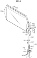
- FIG. 2 is an exploded perspective view of the battery module according to an embodiment of the present disclosure
- FIG. 3 is a diagram showing the top before volume increase of the battery module according to an embodiment of the present disclosure.
- the battery module may include a battery cell 110a, 110b, a busbar 200a, 200b, a short part 300 and a cartridge 400.
- a plurality of battery cells 110a, 110b may be provided, and each battery cell 110a, 110b may be stacked side by side in left-right direction.
- the battery cell 110a, 110b is not limited to a particular type, and various types of secondary batteries may be employed in the battery module according to the present disclosure.
- the battery cell 110a, 110b may include lithium ion batteries, lithium polymer batteries, nickel cadmium batteries, nickel hydrogen batteries and nickel zinc batteries.
- the battery cell 110a, 110b may be a lithium secondary battery.
- the battery cell 110a, 110b may be classified into pouch type, cylindrical and prismatic according to the type of case.
- the battery cell 110a, 110b of the battery module according to the present disclosure may be a pouch-type secondary battery.
- each battery cell 110a, 110b is implemented as a pouch-type secondary battery, as shown in FIG. 2 , each battery cell 110a, 110b is arranged with wide surfaces positioned on the left and right sides, and the wide surfaces between each battery cell 110a, 110b face each other. Additionally, in this case, each battery cell 110a, 110b may have an electrode lead 120a, 120b that protrudes forward and is bent.
- the electrode lead 120a, 120b may include a positive electrode lead and a negative electrode lead, and the positive electrode lead may be connected to a positive electrode plate of an electrode assembly and the negative electrode lead may be connected to a negative electrode plate of the electrode assembly.
- the battery cell 110a, 110b may include a first battery cell 110a disposed on the left side and a second battery cell 110b disposed on the right side.
- each electrode of the first battery cell 110a and the second battery cell 110b is arranged such that the electrode leads 120a, 120b of opposite polarities face the same direction.
- the first battery cell 110a may be disposed with the positive electrode or the first electrode lead 120a facing forward
- the second battery cell 110b may be disposed with the negative electrode or the second electrode lead 120b facing forward.
- first battery cell 110a may be disposed with the negative electrode or the second electrode lead 120b facing rearward
- second battery cell 110b may be disposed with the positive electrode or the first electrode lead 120a facing rearward
- the second electrode lead 120b of the first battery cell 110a and the first electrode lead 120b of the second battery cell 110b may be electrically connected.
- first electrode lead 120a of the first battery cell 110a may be electrically connected to the first busbar 200a as described below to receive the positive voltage from an external voltage source.
- second electrode lead 120b of the second battery cell 110b may be electrically connected to the second busbar 200b as described below to receive the negative voltage from an external voltage source.
- the first busbar 200a may be a busbar that is electrically connected to the first electrode lead 120a of the first battery cell 110a among the busbars 200a, 200b according to the present disclosure
- the second busbar 200b may be a busbar that is electrically connected to the second electrode lead 120b of the second battery cell 110b among the busbars 200a, 200b according to the present disclosure.
- connection structure between the first electrode lead 120a of the first battery cell 110a and the first busbar 200a and the connection structure between the second electrode lead 120b of the second battery cell 110b and the second busbar 200b according to the present disclosure will be described in detail.
- FIG. 4 is a diagram showing the first battery cell, the first busbar, the second battery cell and the second busbar of the battery module according to an embodiment of the present disclosure.
- the first electrode lead 120a of the first battery cell 110a may protrude forward from the first battery cell 110a, and may be bent at an approximately right angle outward from the battery module and come into surface contact with the first busbar 200a.
- the second electrode lead 120b of the second battery cell 110b may protrude forward from the second battery cell 110b and may be bent at an approximately right angle outward from the battery module, i.e., toward the opposite direction to the direction in which the first electrode lead 120a of the first battery cell 110a is bent as described above, and come into surface contact with the second busbar 200b.
- the first busbar 200a and the second busbar 200b are a long plate that runs in up-down direction and is shaped with multiple bends at a right angle.
- the first busbar 200a may include a first bent part B1 that comes into surface contact with the first electrode lead 120a of the first battery cell 110a and is bent forward at a right angle, a second bent part B2 that extends from the first bent part B1 and is bent inward the battery module, a third bent part B3 that extends from the second bent part B2 and is bent forward the battery module, a fourth bent part B4 that extends from the third bent part B3 and is bent outward from the battery module, and a fifth bent part B5 that extends from the fourth bent part B4 and is bent forward the battery module.
- a first bent part B1 that comes into surface contact with the first electrode lead 120a of the first battery cell 110a and is bent forward at a right angle
- a second bent part B2 that extends from the first bent part B1 and is bent inward the battery module
- a third bent part B3 that extends from the second bent part B2 and is bent forward the battery module
- a fourth bent part B4 that extends from the third bent
- the second busbar 200b may include a sixth bent part B6 that comes into surface contact with the second electrode lead 120b of the second battery cell 110b and is bent forward at a right angle, a seventh bent part B7 that extends from the sixth bent part B6 and is bent inward the battery module, an eighth bent part B8 that extends from the seventh bent part B7 and is bent forward the battery module, a ninth bent part B9 that extends from the eighth bent part B8 and is bent outward from the battery module, and a tenth bent part B10 that extends from the ninth bent part B9 and is bent forward the battery module.
- a sixth bent part B6 that comes into surface contact with the second electrode lead 120b of the second battery cell 110b and is bent forward at a right angle
- a seventh bent part B7 that extends from the sixth bent part B6 and is bent inward the battery module
- an eighth bent part B8 that extends from the seventh bent part B7 and is bent forward the battery module
- a ninth bent part B9 that extends from the eighth bent
- first busbar 200a and the second busbar 200b are bent and extend facing each other from the second bent part B2 and the seventh bent part B7, the distance between them reduces, and as they are bent and extend in parallel from the third bent part B3 and the eighth bent part B8 to the front of the battery module, the distance can be maintained.
- the third bent part B3 of the first busbar 200a and the eighth bent part B8 of the second busbar 200b are disposed close to each other, so even though a short terminal (322 of FIG. 3 ) formed at the other end of a slide bar (320 of FIG. 3 ) of the short part (300 of FIG. 3 ) as described below has a small width, it can come into contact with the first busbar 200a and the second busbar 200b simultaneously to cause an electrical short in the first busbar 200a and the second busbar 200b.
- first electrode lead 120a of the first battery cell 110a and the first busbar 200a are brought into surface contact and electrically connected, they may be supported with parts being inserted into a support groove (430 of FIG. 2 ) of the cartridge (400 of FIG. 2 ) as described below.
- the second electrode lead 120b of the second battery cell 110b and the second busbar 200b may be supported with parts being inserted into the support groove (430 of FIG. 2 ) of the cartridge (400 of FIG. 2 ) as described below.
- FIG. 5 is a diagram showing the side before blowing of the blow part of the battery module according to an embodiment of the present disclosure
- FIG. 6 is a diagram showing the side after blowing of the blow part of the battery module according to an embodiment of the present disclosure.
- the first busbar 200a may have a blow part 210a between the first bent part B1 and the second bent part B2, and the blow part 210a has a narrower cross-sectional area than the outer periphery between the first bent part B1 and the second bent part B2.
- the blow part 210a may increase in the resistance value.
- first busbar 200a and the second busbar (200b of FIG. 3 ) are electrically connected to form a short circuit between the first busbar 200a and the second busbar (200b of FIG. 3 ) and the external voltage source, as shown in FIG. 6 , overcurrent flows in the first busbar 200a, producing high temperature resistance heat, and the blow part 210a may be blown.
- the battery module according to the present disclosure may stop charging by blowing of the blow part 210a of the first busbar 200a that electrically connects the first electrode lead 120a of the first battery cell 110a to the external voltage source.
- the battery module according to the present disclosure may apply, to the short part (300 of FIG. 3 ), an expansion force caused by the volume increase of the first battery module 110a due to overcharge, to electrically connect the first busbar 200a and the second busbar (200b of FIG. 3 ). Subsequently, the battery module according to the present disclosure stops charging by blowing of the blow part 210a of the first busbar 200a when a high-current short current flows in the first busbar 200a and the second busbar (200b of FIG. 3 ), thereby preventing the overcharge of the battery module.
- blow part 210a of the battery module is formed in the first busbar 200a
- a blow part of a battery module according to another embodiment of the present disclosure may be formed in the second busbar
- a blow part of a battery module according to still another embodiment of the present disclosure may be formed in both the first busbar and the second busbar.
- the blow part 210a may have a narrower width than adjacent areas, but is not limited thereto, and may be formed from metal having a lower melting point than adjacent areas, and besides, any type that can act as a fuse may be applied as the blow part 210a of the present disclosure without limitation.
- the short part 300 may move to the first busbar 200a and the second busbar 200b and come into contact with the first busbar 200a and the second busbar 200b, causing a short.
- the short part 300 may include an elastic member 310 and a slide bar 320.
- the elastic member 310 may be deformed in the opposite direction to the first busbar 200a and the second busbar 200b by the slide bar 320, and provide an elastic force in the direction b facing the first busbar 200a and the second busbar 200b.
- FIG. 7 is a diagram showing the side of the short part of the battery module according to an embodiment of the present disclosure.
- the elastic member 310 has a spring S inserted between a first plate P1 that contacts the inner side of the cartridge (400 of FIG. 3 ) and a second plate P2 that contact one end of the slide bar 320, to provide an elastic force in the direction facing the first busbar (200a of FIG. 3 ) and the second busbar (200b of FIG. 3 ).
- the slide bar 320 may keep the elastic member 310 in deformed state by the latch coupling of a latching part 321 that protrudes at one end to produce an elastic force from the elastic member 310 and a latching hole (420 of FIG. 2 ) of the cartridge (400 of FIG. 3 ) as described below.
- the slide bar 320 may maintain compression by the latch coupling of the latching part 321 and the latching hole (420 of FIG. 2 ) when the elastic member 320 having the spring inserted between the two plates is compressed in the opposite direction to the first busbar (200a of FIG. 3 ) and the second busbar (200b of FIG. 3 ).
- FIG. 8 is a diagram showing the top after volume increase of the battery module according to an embodiment of the present disclosure.
- the latching part 321 formed at one end of the slide bar 320 may be subjected to the expansion force caused by the volume increase of the first battery cell 110a due to overcharge of the battery module. Accordingly, the latching part 321 may be released from the latch coupling with the latching hole 420 by the expansion force, and the deformed state of the elastic member 310 may be restored.
- the slide bar 320 may move in the direction b facing the first busbar 200a and the second busbar 200b and simultaneously come into contact with the first busbar 200a and the second busbar 200b by the elastic force applied from the elastic member 310 restored from the deformed state.
- the slide bar 320 has a short terminal 322 at the other end to electrically connect the first busbar 200a and the second busbar 200b, causing a short in a circuit including the first busbar 200a and the second busbar 200b.
- the short terminal 322 may be formed from a conductive material.
- the battery module according to an embodiment of the present disclosure is such that the volume of the first battery cell 110a increases in the event of overcharge, producing an expansion force, which is applied to the short part 300, the elastic member 310 in deformed state is restored, and an elastic force produced from the elastic member 310 restored from the deformed state moves the slide bar 320 to the first busbar 200a and the second busbar 200b to electrically connect the first busbar 200a and the second busbar 200b, causing a short.
- FIG. 9 is an equivalent circuit diagram before overcharge of the battery module according to an embodiment of the present disclosure
- FIG. 10 is an equivalent circuit diagram immediately after movement of the short part after overcharge of the battery module according to an embodiment of the present disclosure
- FIG. 11 is an equivalent circuit diagram after blowing of the blow part by movement of the short part after overcharge of the battery module according to an embodiment of the present disclosure.
- the volume of the first battery cell 110a does not increase, and the first busbar 200a and the second busbar 200b may not be electrically shorted.
- the short part 300 moves to the first busbar 200a and the second busbar 200b and comes into contact with the first busbar 200a and the second busbar 200b to electrically connect the first busbar 200a and the second busbar 200b, causing a short.
- a short circuit including the short part 300, the first busbar 200a and the second busbar 200b is formed, allowing a high current I to flow.
- the blow part 210a having a narrow cross-sectional area and a consequential large resistance value blows by generation of high temperature resistance heat, to interrupt the power supply from the external voltage source to the battery module, thereby preventing overcharge.
- FIG. 12 is a diagram showing the cross section of the cartridge of the battery module according to an embodiment of the present disclosure
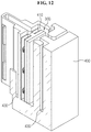
- FIG. 13 is a perspective view showing the inner part of the cartridge of the battery module according to an embodiment of the present disclosure.
- the cartridge 400 is disposed between the first battery cell 110a and the second battery cell 110b, to receive or support at least part of the second electrode lead 120b of the first battery cell 110a, the second electrode lead 120b of the second battery cell 110b, the first busbar 200a, the second busbar 200b and the short part 300.
- the cartridge 400 may support up the first electrode lead 120a of the first battery cell 110a and the first busbar 200a that are brought in surface contact and electrically connected, and support up the second electrode lead 120b of the second battery cell 110b and the second busbar 200b that are brought in surface contact and electrically connected.
- the cartridge 400 may have a support groove 430 of a shape corresponding to the bent shape of the first electrode lead 120a of the first battery cell 110a, the second electrode lead 120b of the second battery cell 110b, the first busbar 200a and the second busbar 200b.
- the cartridge 400 may have a receiving space 410 of a shape corresponding to the shape of the short part 300 on the inner side to receive the short part 300 therein.
- the receiving space 410 of the cartridge 400 may be formed to fit the volume of the elastic member 310 of the short part 300 when restored from the deformed state.
- the receiving space 410 of the cartridge 400 may extend in the direction in which the volume of the elastic member 310 increases in response to the increasing volume when the elastic member 310 of the short part 300 is restored from the deformed state.
- the battery module according to the present disclosure accurately blows the first busbar to interrupt the power supplied from the external voltage source, thereby preventing the overcharge of the battery module and improving the stability of the battery module.
- the battery pack according to the present disclosure includes at least one battery module described above.
- the battery pack may further include a case to receive the battery module and various types of devices to control the charge/discharge of the battery module, for example, a Battery Management System (BMS), a current sensor, a fuse, and the like.
- BMS Battery Management System
- the battery pack according to an embodiment of the present disclosure has a first busbar, a second busbar, a short part and a cartridge for each battery module to perform overcharge prevention for each battery module by blowing the first busbar to interrupt the power supplied from the external voltage source in the event of abnormal expansion of the battery cell.
- the battery module according to the present disclosure may be applied to a vehicle such as an electric vehicle or a hybrid electric vehicle. That is, the vehicle according to the present disclosure may include the battery module according to the present disclosure.
Landscapes
- Chemical & Material Sciences (AREA)
- Chemical Kinetics & Catalysis (AREA)
- Electrochemistry (AREA)
- General Chemical & Material Sciences (AREA)
- Engineering & Computer Science (AREA)
- Manufacturing & Machinery (AREA)
- Materials Engineering (AREA)
- Battery Mounting, Suspending (AREA)
- Connection Of Batteries Or Terminals (AREA)
Priority Applications (1)
| Application Number | Priority Date | Filing Date | Title |
|---|---|---|---|
| PL18806512T PL3540822T3 (pl) | 2017-05-26 | 2018-05-24 | Moduł akumulatorowy, pakiet akumulatorowy i zawierający go samochód |
Applications Claiming Priority (2)
| Application Number | Priority Date | Filing Date | Title |
|---|---|---|---|
| KR1020170065459A KR102201344B1 (ko) | 2017-05-26 | 2017-05-26 | 배터리 모듈과 이를 포함하는 배터리 팩 및 자동차 |
| PCT/KR2018/005918 WO2018217040A1 (ko) | 2017-05-26 | 2018-05-24 | 배터리 모듈과 이를 포함하는 배터리 팩 및 자동차 |
Publications (3)
| Publication Number | Publication Date |
|---|---|
| EP3540822A1 true EP3540822A1 (de) | 2019-09-18 |
| EP3540822A4 EP3540822A4 (de) | 2020-03-25 |
| EP3540822B1 EP3540822B1 (de) | 2020-12-16 |
Family
ID=64396836
Family Applications (1)
| Application Number | Title | Priority Date | Filing Date |
|---|---|---|---|
| EP18806512.2A Active EP3540822B1 (de) | 2017-05-26 | 2018-05-24 | Batteriemodul sowie batteriepack und automobil damit |
Country Status (7)
| Country | Link |
|---|---|
| US (1) | US11121434B2 (de) |
| EP (1) | EP3540822B1 (de) |
| JP (1) | JP7034405B2 (de) |
| KR (1) | KR102201344B1 (de) |
| CN (1) | CN110036506B (de) |
| PL (1) | PL3540822T3 (de) |
| WO (1) | WO2018217040A1 (de) |
Cited By (4)
| Publication number | Priority date | Publication date | Assignee | Title |
|---|---|---|---|---|
| EP3540818A4 (de) * | 2017-06-27 | 2020-01-15 | LG Chem, Ltd. | Batteriemodul sowie batteriepack und fahrzeug damit |
| EP3540823A4 (de) * | 2017-06-15 | 2020-05-06 | LG Chem, Ltd. | Batteriemodul sowie batteriepack und fahrzeug damit |
| US11046206B2 (en) | 2017-07-06 | 2021-06-29 | Lg Chem, Ltd. | Battery module with short-circuit unit, and battery pack and vehicle including the same |
| EP4632956A4 (de) * | 2022-12-05 | 2026-04-22 | Aesc Japan Ltd | Anschlussblock, sammelschienenvorrichtung und batteriepack |
Families Citing this family (4)
| Publication number | Priority date | Publication date | Assignee | Title |
|---|---|---|---|---|
| KR102450418B1 (ko) | 2018-12-07 | 2022-09-30 | 주식회사 엘지에너지솔루션 | 안전성이 개선된 배터리 모듈, 이러한 배터리 모듈을 포함하는 배터리 팩 및 이러한 배터리 팩을 포함하는 자동차 |
| KR102930968B1 (ko) * | 2020-03-18 | 2026-02-25 | 주식회사 엘지에너지솔루션 | 이차 전지 및 전지 모듈 |
| US20240079731A1 (en) * | 2022-09-02 | 2024-03-07 | Ford Global Technologies, Llc | Battery pack electrical connection system and method for electrically connecting battery pack components |
| CN120018687B (zh) * | 2025-04-21 | 2025-08-12 | 宁德时代新能源科技股份有限公司 | 电池组件及其制造方法、用电装置、发电装置 |
Family Cites Families (25)
| Publication number | Priority date | Publication date | Assignee | Title |
|---|---|---|---|---|
| US5521021A (en) | 1994-07-06 | 1996-05-28 | Alexander Manufacturing Corporation | Electric vehicle cell |
| JPH1140203A (ja) * | 1997-07-14 | 1999-02-12 | Hitachi Ltd | 二次電池 |
| KR101046192B1 (ko) | 2007-10-30 | 2011-07-05 | 에스케이이노베이션 주식회사 | 2차 전지용 과충전 안전장치 |
| KR100966549B1 (ko) | 2008-10-14 | 2010-06-29 | 주식회사 엘지화학 | 안전성이 향상된 캡 어셈블리 및 이를 포함하고 있는 원통형 이차전지 |
| KR101072955B1 (ko) * | 2009-08-14 | 2011-10-12 | 에스비리모티브 주식회사 | 전지 모듈 |
| JP5537111B2 (ja) * | 2009-09-30 | 2014-07-02 | 株式会社東芝 | 二次電池装置 |
| KR101294168B1 (ko) * | 2011-09-26 | 2013-08-08 | 기아자동차주식회사 | 배터리의 과충전 방지장치 |
| KR101433199B1 (ko) * | 2011-11-28 | 2014-08-26 | 주식회사 엘지화학 | 배터리 모듈 및 배터리 모듈에 적용되는 버스 바 |
| WO2013103244A1 (ko) * | 2012-01-03 | 2013-07-11 | 주식회사 엘지화학 | 배터리 팩 및 이에 적용되는 커넥팅 바 |
| KR101404712B1 (ko) * | 2012-01-26 | 2014-06-09 | 주식회사 엘지화학 | 안전성이 향상된 전지팩 |
| JP2013178919A (ja) * | 2012-02-28 | 2013-09-09 | Nissan Motor Co Ltd | 電池装置 |
| KR101428331B1 (ko) * | 2012-12-27 | 2014-08-07 | 현대자동차주식회사 | 차량용 배터리모듈의 안전장치 |
| KR101686279B1 (ko) * | 2013-06-19 | 2016-12-13 | 삼성에스디아이 주식회사 | 이차 전지 |
| KR101449307B1 (ko) | 2013-06-28 | 2014-10-08 | 현대자동차주식회사 | 배터리 안전장치 |
| WO2015068871A1 (ko) * | 2013-11-08 | 2015-05-14 | 에스케이이노베이션 주식회사 | 이차 전지용 배터리 셀의 과충전 방지장치 |
| KR20150053597A (ko) | 2013-11-08 | 2015-05-18 | 삼성에스디아이 주식회사 | 배터리 모듈 |
| KR20150071571A (ko) * | 2013-12-18 | 2015-06-26 | 현대자동차주식회사 | 차량 배터리 과충전 방지장치 |
| US10396334B2 (en) * | 2014-03-31 | 2019-08-27 | Lg Chem, Ltd. | Battery module and battery pack comprising same |
| KR101679413B1 (ko) * | 2015-04-03 | 2016-11-25 | (주)오렌지파워 | 중공형 이차전지 |
| EP2996189A4 (de) | 2014-07-14 | 2016-11-30 | Orange Power Ltd | Hohle sekundärbatterie |
| KR101773105B1 (ko) * | 2014-07-31 | 2017-08-30 | 주식회사 엘지화학 | 배터리 모듈 |
| KR102324863B1 (ko) | 2014-10-30 | 2021-11-09 | 현대모비스 주식회사 | 배터리 과충전 방지구조 |
| KR101792820B1 (ko) | 2014-12-22 | 2017-11-01 | 주식회사 엘지화학 | 파단 유도부가 형성된 단자 접속부재 및 댐핑부재를 포함하는 전지팩 |
| KR20170016065A (ko) | 2015-08-03 | 2017-02-13 | 에스케이이노베이션 주식회사 | 이차 전지 |
| KR102017789B1 (ko) | 2015-12-03 | 2019-09-03 | 주식회사 엘지화학 | 반사 방지 필름 |
-
2017
- 2017-05-26 KR KR1020170065459A patent/KR102201344B1/ko active Active
-
2018
- 2018-05-24 EP EP18806512.2A patent/EP3540822B1/de active Active
- 2018-05-24 PL PL18806512T patent/PL3540822T3/pl unknown
- 2018-05-24 CN CN201880004750.2A patent/CN110036506B/zh active Active
- 2018-05-24 US US16/348,023 patent/US11121434B2/en active Active
- 2018-05-24 WO PCT/KR2018/005918 patent/WO2018217040A1/ko not_active Ceased
- 2018-05-24 JP JP2019530160A patent/JP7034405B2/ja active Active
Cited By (7)
| Publication number | Priority date | Publication date | Assignee | Title |
|---|---|---|---|---|
| EP3540823A4 (de) * | 2017-06-15 | 2020-05-06 | LG Chem, Ltd. | Batteriemodul sowie batteriepack und fahrzeug damit |
| US11011802B2 (en) | 2017-06-15 | 2021-05-18 | Lg Chem, Ltd. | Battery module with short-circuit unit, and battery pack and vehicle including same |
| EP3540818A4 (de) * | 2017-06-27 | 2020-01-15 | LG Chem, Ltd. | Batteriemodul sowie batteriepack und fahrzeug damit |
| US10892468B2 (en) | 2017-06-27 | 2021-01-12 | Lg Chem, Ltd. | Battery module with short-circuit unit, and battery pack and vehicle including the same |
| US11046206B2 (en) | 2017-07-06 | 2021-06-29 | Lg Chem, Ltd. | Battery module with short-circuit unit, and battery pack and vehicle including the same |
| EP3512008B1 (de) * | 2017-07-06 | 2023-01-11 | LG Energy Solution, Ltd. | Batteriemodul sowie batteriepack und fahrzeug damit |
| EP4632956A4 (de) * | 2022-12-05 | 2026-04-22 | Aesc Japan Ltd | Anschlussblock, sammelschienenvorrichtung und batteriepack |
Also Published As
| Publication number | Publication date |
|---|---|
| US20190341595A1 (en) | 2019-11-07 |
| WO2018217040A1 (ko) | 2018-11-29 |
| KR102201344B1 (ko) | 2021-01-08 |
| EP3540822B1 (de) | 2020-12-16 |
| CN110036506A (zh) | 2019-07-19 |
| JP7034405B2 (ja) | 2022-03-14 |
| CN110036506B (zh) | 2021-11-26 |
| JP2020501318A (ja) | 2020-01-16 |
| PL3540822T3 (pl) | 2021-05-04 |
| KR20180129433A (ko) | 2018-12-05 |
| EP3540822A4 (de) | 2020-03-25 |
| US11121434B2 (en) | 2021-09-14 |
Similar Documents
| Publication | Publication Date | Title |
|---|---|---|
| US11121434B2 (en) | Battery module and battery pack and vehicle comprising the same | |
| CN109844996B (zh) | 电池模块和包括该电池模块的电池组和车辆 | |
| CN109891627B (zh) | 电池模块和包括所述电池模块的电池组和车辆 | |
| EP2212941B1 (de) | Batteriemodul mit erhöhter sicherheit und mittelgrosse oder grosse batteriepackung damit | |
| EP2768047B1 (de) | Batteriepackung mit erhöhter sicherheit | |
| CN109923695B (zh) | 电池模块以及包括该电池模块的电池组和车辆 | |
| KR102308168B1 (ko) | 배터리 모듈과 이를 포함하는 배터리 팩 및 자동차 | |
| CN103636029A (zh) | 具有改进的安全性的电池组 | |
| KR102250180B1 (ko) | 배터리 모듈과 이를 포함하는 배터리 팩 및 자동차 | |
| KR102249457B1 (ko) | 배터리 모듈과 이를 포함하는 배터리 팩 및 자동차 | |
| CN109891636B (zh) | 电池模块和包括该电池模块的电池组 | |
| KR102267056B1 (ko) | 배터리 모듈과 이를 포함하는 배터리 팩 및 자동차 | |
| KR102378571B1 (ko) | 배터리 모듈, 이를 포함하는 배터리 팩 및 자동차 |
Legal Events
| Date | Code | Title | Description |
|---|---|---|---|
| STAA | Information on the status of an ep patent application or granted ep patent |
Free format text: STATUS: THE INTERNATIONAL PUBLICATION HAS BEEN MADE |
|
| PUAI | Public reference made under article 153(3) epc to a published international application that has entered the european phase |
Free format text: ORIGINAL CODE: 0009012 |
|
| STAA | Information on the status of an ep patent application or granted ep patent |
Free format text: STATUS: REQUEST FOR EXAMINATION WAS MADE |
|
| 17P | Request for examination filed |
Effective date: 20190612 |
|
| AK | Designated contracting states |
Kind code of ref document: A1 Designated state(s): AL AT BE BG CH CY CZ DE DK EE ES FI FR GB GR HR HU IE IS IT LI LT LU LV MC MK MT NL NO PL PT RO RS SE SI SK SM TR |
|
| AX | Request for extension of the european patent |
Extension state: BA ME |
|
| A4 | Supplementary search report drawn up and despatched |
Effective date: 20200220 |
|
| RIC1 | Information provided on ipc code assigned before grant |
Ipc: H01M 10/42 20060101ALI20200215BHEP Ipc: H01M 2/34 20060101AFI20200215BHEP Ipc: H01M 2/10 20060101ALI20200215BHEP Ipc: H01M 2/20 20060101ALI20200215BHEP Ipc: H01M 2/26 20060101ALI20200215BHEP |
|
| DAV | Request for validation of the european patent (deleted) | ||
| DAX | Request for extension of the european patent (deleted) | ||
| GRAP | Despatch of communication of intention to grant a patent |
Free format text: ORIGINAL CODE: EPIDOSNIGR1 |
|
| STAA | Information on the status of an ep patent application or granted ep patent |
Free format text: STATUS: GRANT OF PATENT IS INTENDED |
|
| GRAS | Grant fee paid |
Free format text: ORIGINAL CODE: EPIDOSNIGR3 |
|
| INTG | Intention to grant announced |
Effective date: 20201016 |
|
| GRAA | (expected) grant |
Free format text: ORIGINAL CODE: 0009210 |
|
| STAA | Information on the status of an ep patent application or granted ep patent |
Free format text: STATUS: THE PATENT HAS BEEN GRANTED |
|
| REG | Reference to a national code |
Ref country code: DE Ref legal event code: R079 Ref document number: 602018010931 Country of ref document: DE Free format text: PREVIOUS MAIN CLASS: H01M0002340000 Ipc: H01M0050572000 |
|
| AK | Designated contracting states |
Kind code of ref document: B1 Designated state(s): AL AT BE BG CH CY CZ DE DK EE ES FI FR GB GR HR HU IE IS IT LI LT LU LV MC MK MT NL NO PL PT RO RS SE SI SK SM TR |
|
| REG | Reference to a national code |
Ref country code: GB Ref legal event code: FG4D |
|
| REG | Reference to a national code |
Ref country code: IE Ref legal event code: FG4D |
|
| REG | Reference to a national code |
Ref country code: DE Ref legal event code: R096 Ref document number: 602018010931 Country of ref document: DE |
|
| REG | Reference to a national code |
Ref country code: AT Ref legal event code: REF Ref document number: 1346401 Country of ref document: AT Kind code of ref document: T Effective date: 20210115 |
|
| REG | Reference to a national code |
Ref country code: SE Ref legal event code: TRGR |
|
| PG25 | Lapsed in a contracting state [announced via postgrant information from national office to epo] |
Ref country code: RS Free format text: LAPSE BECAUSE OF FAILURE TO SUBMIT A TRANSLATION OF THE DESCRIPTION OR TO PAY THE FEE WITHIN THE PRESCRIBED TIME-LIMIT Effective date: 20201216 Ref country code: FI Free format text: LAPSE BECAUSE OF FAILURE TO SUBMIT A TRANSLATION OF THE DESCRIPTION OR TO PAY THE FEE WITHIN THE PRESCRIBED TIME-LIMIT Effective date: 20201216 Ref country code: NO Free format text: LAPSE BECAUSE OF FAILURE TO SUBMIT A TRANSLATION OF THE DESCRIPTION OR TO PAY THE FEE WITHIN THE PRESCRIBED TIME-LIMIT Effective date: 20210316 Ref country code: GR Free format text: LAPSE BECAUSE OF FAILURE TO SUBMIT A TRANSLATION OF THE DESCRIPTION OR TO PAY THE FEE WITHIN THE PRESCRIBED TIME-LIMIT Effective date: 20210317 |
|
| REG | Reference to a national code |
Ref country code: AT Ref legal event code: MK05 Ref document number: 1346401 Country of ref document: AT Kind code of ref document: T Effective date: 20201216 |
|
| REG | Reference to a national code |
Ref country code: NL Ref legal event code: MP Effective date: 20201216 |
|
| PG25 | Lapsed in a contracting state [announced via postgrant information from national office to epo] |
Ref country code: BG Free format text: LAPSE BECAUSE OF FAILURE TO SUBMIT A TRANSLATION OF THE DESCRIPTION OR TO PAY THE FEE WITHIN THE PRESCRIBED TIME-LIMIT Effective date: 20210316 Ref country code: LV Free format text: LAPSE BECAUSE OF FAILURE TO SUBMIT A TRANSLATION OF THE DESCRIPTION OR TO PAY THE FEE WITHIN THE PRESCRIBED TIME-LIMIT Effective date: 20201216 |
|
| PG25 | Lapsed in a contracting state [announced via postgrant information from national office to epo] |
Ref country code: HR Free format text: LAPSE BECAUSE OF FAILURE TO SUBMIT A TRANSLATION OF THE DESCRIPTION OR TO PAY THE FEE WITHIN THE PRESCRIBED TIME-LIMIT Effective date: 20201216 Ref country code: NL Free format text: LAPSE BECAUSE OF FAILURE TO SUBMIT A TRANSLATION OF THE DESCRIPTION OR TO PAY THE FEE WITHIN THE PRESCRIBED TIME-LIMIT Effective date: 20201216 |
|
| REG | Reference to a national code |
Ref country code: LT Ref legal event code: MG9D |
|
| PG25 | Lapsed in a contracting state [announced via postgrant information from national office to epo] |
Ref country code: SM Free format text: LAPSE BECAUSE OF FAILURE TO SUBMIT A TRANSLATION OF THE DESCRIPTION OR TO PAY THE FEE WITHIN THE PRESCRIBED TIME-LIMIT Effective date: 20201216 Ref country code: SK Free format text: LAPSE BECAUSE OF FAILURE TO SUBMIT A TRANSLATION OF THE DESCRIPTION OR TO PAY THE FEE WITHIN THE PRESCRIBED TIME-LIMIT Effective date: 20201216 Ref country code: CZ Free format text: LAPSE BECAUSE OF FAILURE TO SUBMIT A TRANSLATION OF THE DESCRIPTION OR TO PAY THE FEE WITHIN THE PRESCRIBED TIME-LIMIT Effective date: 20201216 Ref country code: EE Free format text: LAPSE BECAUSE OF FAILURE TO SUBMIT A TRANSLATION OF THE DESCRIPTION OR TO PAY THE FEE WITHIN THE PRESCRIBED TIME-LIMIT Effective date: 20201216 Ref country code: LT Free format text: LAPSE BECAUSE OF FAILURE TO SUBMIT A TRANSLATION OF THE DESCRIPTION OR TO PAY THE FEE WITHIN THE PRESCRIBED TIME-LIMIT Effective date: 20201216 Ref country code: RO Free format text: LAPSE BECAUSE OF FAILURE TO SUBMIT A TRANSLATION OF THE DESCRIPTION OR TO PAY THE FEE WITHIN THE PRESCRIBED TIME-LIMIT Effective date: 20201216 Ref country code: PT Free format text: LAPSE BECAUSE OF FAILURE TO SUBMIT A TRANSLATION OF THE DESCRIPTION OR TO PAY THE FEE WITHIN THE PRESCRIBED TIME-LIMIT Effective date: 20210416 |
|
| PG25 | Lapsed in a contracting state [announced via postgrant information from national office to epo] |
Ref country code: AT Free format text: LAPSE BECAUSE OF FAILURE TO SUBMIT A TRANSLATION OF THE DESCRIPTION OR TO PAY THE FEE WITHIN THE PRESCRIBED TIME-LIMIT Effective date: 20201216 |
|
| REG | Reference to a national code |
Ref country code: DE Ref legal event code: R097 Ref document number: 602018010931 Country of ref document: DE |
|
| PG25 | Lapsed in a contracting state [announced via postgrant information from national office to epo] |
Ref country code: IS Free format text: LAPSE BECAUSE OF FAILURE TO SUBMIT A TRANSLATION OF THE DESCRIPTION OR TO PAY THE FEE WITHIN THE PRESCRIBED TIME-LIMIT Effective date: 20210416 |
|
| PLBE | No opposition filed within time limit |
Free format text: ORIGINAL CODE: 0009261 |
|
| STAA | Information on the status of an ep patent application or granted ep patent |
Free format text: STATUS: NO OPPOSITION FILED WITHIN TIME LIMIT |
|
| PG25 | Lapsed in a contracting state [announced via postgrant information from national office to epo] |
Ref country code: IT Free format text: LAPSE BECAUSE OF FAILURE TO SUBMIT A TRANSLATION OF THE DESCRIPTION OR TO PAY THE FEE WITHIN THE PRESCRIBED TIME-LIMIT Effective date: 20201216 Ref country code: AL Free format text: LAPSE BECAUSE OF FAILURE TO SUBMIT A TRANSLATION OF THE DESCRIPTION OR TO PAY THE FEE WITHIN THE PRESCRIBED TIME-LIMIT Effective date: 20201216 |
|
| 26N | No opposition filed |
Effective date: 20210917 |
|
| PG25 | Lapsed in a contracting state [announced via postgrant information from national office to epo] |
Ref country code: DK Free format text: LAPSE BECAUSE OF FAILURE TO SUBMIT A TRANSLATION OF THE DESCRIPTION OR TO PAY THE FEE WITHIN THE PRESCRIBED TIME-LIMIT Effective date: 20201216 |
|
| REG | Reference to a national code |
Ref country code: CH Ref legal event code: PL |
|
| PG25 | Lapsed in a contracting state [announced via postgrant information from national office to epo] |
Ref country code: ES Free format text: LAPSE BECAUSE OF FAILURE TO SUBMIT A TRANSLATION OF THE DESCRIPTION OR TO PAY THE FEE WITHIN THE PRESCRIBED TIME-LIMIT Effective date: 20201216 Ref country code: MC Free format text: LAPSE BECAUSE OF FAILURE TO SUBMIT A TRANSLATION OF THE DESCRIPTION OR TO PAY THE FEE WITHIN THE PRESCRIBED TIME-LIMIT Effective date: 20201216 Ref country code: LU Free format text: LAPSE BECAUSE OF NON-PAYMENT OF DUE FEES Effective date: 20210524 Ref country code: LI Free format text: LAPSE BECAUSE OF NON-PAYMENT OF DUE FEES Effective date: 20210531 Ref country code: CH Free format text: LAPSE BECAUSE OF NON-PAYMENT OF DUE FEES Effective date: 20210531 |
|
| REG | Reference to a national code |
Ref country code: BE Ref legal event code: MM Effective date: 20210531 |
|
| PG25 | Lapsed in a contracting state [announced via postgrant information from national office to epo] |
Ref country code: SI Free format text: LAPSE BECAUSE OF FAILURE TO SUBMIT A TRANSLATION OF THE DESCRIPTION OR TO PAY THE FEE WITHIN THE PRESCRIBED TIME-LIMIT Effective date: 20201216 |
|
| PG25 | Lapsed in a contracting state [announced via postgrant information from national office to epo] |
Ref country code: IE Free format text: LAPSE BECAUSE OF NON-PAYMENT OF DUE FEES Effective date: 20210524 |
|
| PG25 | Lapsed in a contracting state [announced via postgrant information from national office to epo] |
Ref country code: IS Free format text: LAPSE BECAUSE OF FAILURE TO SUBMIT A TRANSLATION OF THE DESCRIPTION OR TO PAY THE FEE WITHIN THE PRESCRIBED TIME-LIMIT Effective date: 20210416 |
|
| PG25 | Lapsed in a contracting state [announced via postgrant information from national office to epo] |
Ref country code: BE Free format text: LAPSE BECAUSE OF NON-PAYMENT OF DUE FEES Effective date: 20210531 |
|
| REG | Reference to a national code |
Ref country code: DE Ref legal event code: R081 Ref document number: 602018010931 Country of ref document: DE Owner name: LG ENERGY SOLUTION, LTD., KR Free format text: FORMER OWNER: LG CHEM, LTD., SEOUL, KR |
|
| P01 | Opt-out of the competence of the unified patent court (upc) registered |
Effective date: 20230512 |
|
| PG25 | Lapsed in a contracting state [announced via postgrant information from national office to epo] |
Ref country code: CY Free format text: LAPSE BECAUSE OF FAILURE TO SUBMIT A TRANSLATION OF THE DESCRIPTION OR TO PAY THE FEE WITHIN THE PRESCRIBED TIME-LIMIT Effective date: 20201216 |
|
| PG25 | Lapsed in a contracting state [announced via postgrant information from national office to epo] |
Ref country code: HU Free format text: LAPSE BECAUSE OF FAILURE TO SUBMIT A TRANSLATION OF THE DESCRIPTION OR TO PAY THE FEE WITHIN THE PRESCRIBED TIME-LIMIT; INVALID AB INITIO Effective date: 20180524 |
|
| REG | Reference to a national code |
Ref country code: GB Ref legal event code: 732E Free format text: REGISTERED BETWEEN 20230901 AND 20230906 |
|
| PG25 | Lapsed in a contracting state [announced via postgrant information from national office to epo] |
Ref country code: MK Free format text: LAPSE BECAUSE OF FAILURE TO SUBMIT A TRANSLATION OF THE DESCRIPTION OR TO PAY THE FEE WITHIN THE PRESCRIBED TIME-LIMIT Effective date: 20201216 |
|
| PG25 | Lapsed in a contracting state [announced via postgrant information from national office to epo] |
Ref country code: TR Free format text: LAPSE BECAUSE OF FAILURE TO SUBMIT A TRANSLATION OF THE DESCRIPTION OR TO PAY THE FEE WITHIN THE PRESCRIBED TIME-LIMIT Effective date: 20201216 |
|
| PG25 | Lapsed in a contracting state [announced via postgrant information from national office to epo] |
Ref country code: MT Free format text: LAPSE BECAUSE OF FAILURE TO SUBMIT A TRANSLATION OF THE DESCRIPTION OR TO PAY THE FEE WITHIN THE PRESCRIBED TIME-LIMIT Effective date: 20201216 |
|
| PGFP | Annual fee paid to national office [announced via postgrant information from national office to epo] |
Ref country code: PL Payment date: 20250423 Year of fee payment: 8 Ref country code: DE Payment date: 20250422 Year of fee payment: 8 |
|
| PGFP | Annual fee paid to national office [announced via postgrant information from national office to epo] |
Ref country code: FR Payment date: 20250422 Year of fee payment: 8 |
|
| PGFP | Annual fee paid to national office [announced via postgrant information from national office to epo] |
Ref country code: SE Payment date: 20250422 Year of fee payment: 8 |
|
| PGFP | Annual fee paid to national office [announced via postgrant information from national office to epo] |
Ref country code: GB Payment date: 20260324 Year of fee payment: 9 |