EP3543011A1 - Procédé de mise en forme tridimensionnelle - Google Patents
Procédé de mise en forme tridimensionnelle Download PDFInfo
- Publication number
- EP3543011A1 EP3543011A1 EP19162412.1A EP19162412A EP3543011A1 EP 3543011 A1 EP3543011 A1 EP 3543011A1 EP 19162412 A EP19162412 A EP 19162412A EP 3543011 A1 EP3543011 A1 EP 3543011A1
- Authority
- EP
- European Patent Office
- Prior art keywords
- cutting
- machining unit
- thickness
- upper side
- machining
- Prior art date
- Legal status (The legal status is an assumption and is not a legal conclusion. Google has not performed a legal analysis and makes no representation as to the accuracy of the status listed.)
- Granted
Links
Images

Classifications
-
- B—PERFORMING OPERATIONS; TRANSPORTING
- B23—MACHINE TOOLS; METAL-WORKING NOT OTHERWISE PROVIDED FOR
- B23C—MILLING
- B23C1/00—Milling machines not designed for particular work or special operations
- B23C1/12—Milling machines not designed for particular work or special operations with spindle adjustable to different angles, e.g. either horizontal or vertical
-
- B—PERFORMING OPERATIONS; TRANSPORTING
- B29—WORKING OF PLASTICS; WORKING OF SUBSTANCES IN A PLASTIC STATE IN GENERAL
- B29C—SHAPING OR JOINING OF PLASTICS; SHAPING OF MATERIAL IN A PLASTIC STATE, NOT OTHERWISE PROVIDED FOR; AFTER-TREATMENT OF THE SHAPED PRODUCTS, e.g. REPAIRING
- B29C64/00—Additive manufacturing, i.e. manufacturing of three-dimensional [3D] objects by additive deposition, additive agglomeration or additive layering, e.g. by 3D printing, stereolithography or selective laser sintering
- B29C64/30—Auxiliary operations or equipment
-
- B—PERFORMING OPERATIONS; TRANSPORTING
- B23—MACHINE TOOLS; METAL-WORKING NOT OTHERWISE PROVIDED FOR
- B23C—MILLING
- B23C3/00—Milling particular work; Special milling operations; Machines therefor
- B23C3/12—Trimming or finishing edges, e.g. deburring welded corners
-
- B—PERFORMING OPERATIONS; TRANSPORTING
- B23—MACHINE TOOLS; METAL-WORKING NOT OTHERWISE PROVIDED FOR
- B23K—SOLDERING OR UNSOLDERING; WELDING; CLADDING OR PLATING BY SOLDERING OR WELDING; CUTTING BY APPLYING HEAT LOCALLY, e.g. FLAME CUTTING; WORKING BY LASER BEAM
- B23K26/00—Working by laser beam, e.g. welding, cutting or boring
- B23K26/34—Laser welding for purposes other than joining
- B23K26/342—Build-up welding
-
- B—PERFORMING OPERATIONS; TRANSPORTING
- B23—MACHINE TOOLS; METAL-WORKING NOT OTHERWISE PROVIDED FOR
- B23P—METAL-WORKING NOT OTHERWISE PROVIDED FOR; COMBINED OPERATIONS; UNIVERSAL MACHINE TOOLS
- B23P17/00—Metal-working operations, not covered by a single other subclass or another group in this subclass
-
- B—PERFORMING OPERATIONS; TRANSPORTING
- B29—WORKING OF PLASTICS; WORKING OF SUBSTANCES IN A PLASTIC STATE IN GENERAL
- B29C—SHAPING OR JOINING OF PLASTICS; SHAPING OF MATERIAL IN A PLASTIC STATE, NOT OTHERWISE PROVIDED FOR; AFTER-TREATMENT OF THE SHAPED PRODUCTS, e.g. REPAIRING
- B29C64/00—Additive manufacturing, i.e. manufacturing of three-dimensional [3D] objects by additive deposition, additive agglomeration or additive layering, e.g. by 3D printing, stereolithography or selective laser sintering
- B29C64/10—Processes of additive manufacturing
- B29C64/141—Processes of additive manufacturing using only solid materials
- B29C64/153—Processes of additive manufacturing using only solid materials using layers of powder being selectively joined, e.g. by selective laser sintering or melting
-
- B—PERFORMING OPERATIONS; TRANSPORTING
- B29—WORKING OF PLASTICS; WORKING OF SUBSTANCES IN A PLASTIC STATE IN GENERAL
- B29C—SHAPING OR JOINING OF PLASTICS; SHAPING OF MATERIAL IN A PLASTIC STATE, NOT OTHERWISE PROVIDED FOR; AFTER-TREATMENT OF THE SHAPED PRODUCTS, e.g. REPAIRING
- B29C64/00—Additive manufacturing, i.e. manufacturing of three-dimensional [3D] objects by additive deposition, additive agglomeration or additive layering, e.g. by 3D printing, stereolithography or selective laser sintering
- B29C64/10—Processes of additive manufacturing
- B29C64/188—Processes of additive manufacturing involving additional operations performed on the added layers, e.g. smoothing, grinding or thickness control
-
- B—PERFORMING OPERATIONS; TRANSPORTING
- B33—ADDITIVE MANUFACTURING TECHNOLOGY
- B33Y—ADDITIVE MANUFACTURING, i.e. MANUFACTURING OF THREE-DIMENSIONAL [3D] OBJECTS BY ADDITIVE DEPOSITION, ADDITIVE AGGLOMERATION OR ADDITIVE LAYERING, e.g. BY 3D PRINTING, STEREOLITHOGRAPHY OR SELECTIVE LASER SINTERING
- B33Y10/00—Processes of additive manufacturing
-
- B—PERFORMING OPERATIONS; TRANSPORTING
- B23—MACHINE TOOLS; METAL-WORKING NOT OTHERWISE PROVIDED FOR
- B23C—MILLING
- B23C2220/00—Details of milling processes
- B23C2220/16—Chamferring
-
- B—PERFORMING OPERATIONS; TRANSPORTING
- B23—MACHINE TOOLS; METAL-WORKING NOT OTHERWISE PROVIDED FOR
- B23C—MILLING
- B23C2228/00—Properties of materials of tools or workpieces, materials of tools or workpieces applied in a specific manner
- B23C2228/49—Sintered
-
- B—PERFORMING OPERATIONS; TRANSPORTING
- B23—MACHINE TOOLS; METAL-WORKING NOT OTHERWISE PROVIDED FOR
- B23C—MILLING
- B23C2270/00—Details of milling machines, milling processes or milling tools not otherwise provided for
- B23C2270/20—Milling external areas of components
-
- B—PERFORMING OPERATIONS; TRANSPORTING
- B29—WORKING OF PLASTICS; WORKING OF SUBSTANCES IN A PLASTIC STATE IN GENERAL
- B29C—SHAPING OR JOINING OF PLASTICS; SHAPING OF MATERIAL IN A PLASTIC STATE, NOT OTHERWISE PROVIDED FOR; AFTER-TREATMENT OF THE SHAPED PRODUCTS, e.g. REPAIRING
- B29C59/00—Surface shaping of articles, e.g. embossing; Apparatus therefor
- B29C59/02—Surface shaping of articles, e.g. embossing; Apparatus therefor by mechanical means, e.g. pressing
- B29C2059/027—Grinding; Polishing
Definitions
- the present invention relates to a three-dimensional shaping method that assumes provision of a cutting allowance on a cutting surface.
- Cutting allowance also known as machining allowance, is defined as surplus dimensions provided in advance in a material to allow finishing to the prescribed dimensions in cutting (see, for example, " Dictionary of Mechanical Terms,” Nikkan Kogyo Shimbun, Ltd., November 28, 1997, First Printing of First Editi on).
- Patent Document 1 incidentally, describes reduction in the amount of cutting allowance in three-dimensional shaping, but does not describe in any way setting the cutting allowance for the lamination step or setting the order for the subsequent cutting steps.
- Patent Document 1 Japanese Published Unexamined Patent Application No. 2017-144446
- the present invention includes following three basic configurations I, II, III.
- the lamination step of the present invention includes several repetitions of formation of a powder layer, flattening of the powder layer with a squeegee, and sintering by irradiation with a laser beam or electron beam.
- the cutting surface is classified as either a peripheral side or the upper side, as described in each step of process 1.
- Sides along the vertical direction are typical examples of peripheral sides, but instead of the sides along the vertical direction, they may also refer to surfaces that form slanted sides with respect to the vertical direction or curved sides due to outward protrusion, and that are to be cut by the cutting blade at the lengthwise side section of the cutting tool 3.
- the upper sides are typically horizontal sides, but instead of the horizontal sides, they may also refer to surfaces that form slanted sides with respect to the horizontal direction or curved sides due to inward or outward protrusion, and that are to be cut by the cutting blade at the tip of the cutting tool 3.
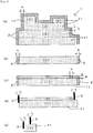
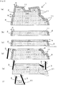
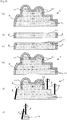
- Figs. 1 , 2 , 3 show each process of the basic configurations I, II, III, Fig. 1 showing a case where all of the peripheral sides and the upper sides are sides along the vertical direction, Fig. 2 showing a case where most of the peripheral sides and upper sides are slanted sides, and Fig. 3 showing a case where the peripheral sides and upper sides at the highest location and the second highest location at the top are all outwardly protruding curved sides.
- the machining units 11 described in step 1 of the basic configurations I, II, III are the units of lamination and cutting that form the overall shape of the object to be shaped 1, as shown by the regions demarcated by (i), (ii), (iii), (iv), (v) in (a) of Figs. 1 , 2 , 3 , and they have four peripheral sides, as well as upper sides surrounded by parts of the peripheral sides (the upper sides of (i), (ii), (iii) in (a) of each of Figs. 1 , 2 , 3 ) or upper sides surrounded by all of the peripheral sides (the upper sides (iv), (v) in (a) of each of Figs. 1 , 2 , 3 ).
- the upper sides at the top are all necessarily surrounded by peripheral sides, but upper sides that are fully surrounded by peripheral sides do not necessarily have to be located at the top, which is clear from the upper side of the machining unit 11 in region (iv) shown in (a) of each of Figs. 1 , 2 , 3 .
- step 1 The basic configurations I, II, III have in common the aspect of step 1, as shown in (a) of Figs. 1 , 2 , 3 , which includes:
- step 1 After setting each machining unit 11 and cutting allowance 2 in step 1, the basic configurations I, II, III have in common the aspect of step 2(1), as shown in (b) of each of Figs. 1 , 2 , 3 , in which lamination by addition of the thickness "a" in the horizontal direction for the machining unit 11 located on the lower side, and the peripheral sides, is continued until reaching the upper side of the machining unit 11.
- step 2(1) After continuing the lamination of step 2(1), the basic configurations I, II, III have in common the aspect of step 2(2), as shown in (c) of each of Figs. 1 , 2 , 3 , in which lamination based on the addition of step 2(1) on the machining unit 11 of step 2(1) and the machining units 11 located adjacent to and above the machining unit 11 in the horizontal direction, is continued in the region of the thickness "b" in the direction of the upper side, or when no machining unit 11 is present adjacent to the machining unit 11 of step 2(1), as in (iv) and (v) of the machining units 11 of (a) in each of Figs. 1 , 2 , 3 , lamination based on the addition of step 2(1) is continued only in the machining region of step 2(1), in the region of the thickness "b" in the direction of the upper side.
- the cutting step of 2(3) is used in which cutting is performed for the cutting allowance 2 of the thickness "a" on the peripheral sides of the machining units 11 of step 2(1) and step 2(2) and cutting of the cutting allowance 2 of the thickness "b" on the upper side, and, in the region where the peripheral side of step 2(1) and the adjacent peripheral sides of step 2(2) are continuous, cutting is performed for the cutting allowance 2 of the thickness "a” on both peripheral sides as in the peripheral sides on the left sides of machining unit 11 (i) and machining unit 11 (ii) in Figs. 1(c), (d) .
- step 2(3) for the basic configuration II, after carrying out step 2(3) in which the steps of step 2(1) and (2) are repeated as shown in Fig. 2(d) , without immediately starting the cutting step after the step of 2(2), the repetition is continued as long as the total length along the direction orthogonal to the horizontal direction of the peripheral sides formed by the repetition does not exceed the length of the cutting blade on the lengthwise side section of the cutting tool 3, and the step of 2(4) is carried out for cutting of the cutting allowance 2 of the thickness "a" on the peripheral sides formed by step (3) and cutting of the cutting allowance 2 of the thickness "b" on the upper side.
- step 2(3) the lamination step of 2(3) is used, in which the laminations of 2(1) and 2(2) are continuously repeated from the lowest machining unit 11 until reaching the topmost machining unit 11, as shown in Fig. 3(d) .
- the step of 3 is carried out for cutting the cutting allowance 2 of the thickness "a" on the peripheral side and cutting the cutting allowance 2 of the thickness "b" on the upper side of each machining unit 11, with shaping of the object to be shaped 1 being completed upon reaching cutting at the final stage shown in Fig. 3(f) .
- step 3 of the basic configuration III as shown in Fig. 3(e) , it is essential to use a cutting tool 3 having a cutting blade on the lengthwise side section that is longer than the peripheral side with the longest continuous length in the direction orthogonal to the horizontal direction, of the peripheral sides formed in step 2.
- a blade having such the lengthwise width introduces a technical drawback compared to the basic configuration I, in that a prescribed thickness of the lengthwise cross-section is necessary, and it often cannot be applied for fine molding.
- the basic configuration III is superior in terms of the features described above, while also allowing simpler control.
- the basic configuration II can produce an intermediate state between the basic configurations I and III, to the extent of the effect of lamination of the adjacent machining units 11, while being superior in terms of not requiring provision of a special cutting tool 3 as for the basic configuration III.
- the thickness "b" of the cutting allowance 2 on the upper sides is set to be thicker than the thickness "a" of the cutting allowance 2 at the peripheral sides, the reason being that for the cutting allowance 2 on the upper side, the sintered cutting allowance 2 has a high degree of heat contraction due to the load of the cutting allowance 2 region itself during the heat contraction.
- peripheral sides and the upper sides are distinguished by the cutting blade of the cutting tool 3, as already explained, and the peripheral sides are not limited to being vertical planes, and may also be slanted sides with respect to the vertical direction, or outwardly protruding curved sides with respect to the vertical direction, while the upper sides are not limited to being horizontal sides, and may also be slanted sides with respect to the horizontal direction, or curved sides with respect to the horizontal direction.
- the directions of the peripheral sides and the directions of the upper sides can be distinguished by specific angles, and in most cases, they will be distinguished by a range of 60° to 75° with respect to the horizontal direction.
- Cutting of the cutting allowance 2 on the peripheral sides can be realized even in a case that the peripheral sides have undercutting represented by the left wall section of (iv) of the machining units 11 of Fig. 2(a) , for example.
- cutting can be carried out by moving the cutting tool 3 after setting the cutting blade on the lengthwise side section of the cutting tool 3 to the direction of undercutting, along the direction of undercutting.
- the cutting allowance 2 of the thickness "a" formed on the peripheral sides is shaved off with a cutting blade at the tip of the cutting tool 3.
- peripheral sides When the outer peripheral sides form curves depressed inward with respect to the vertical direction, the peripheral sides cannot be shaved off by a blade at the side sections in the lengthwise direction of the cutting tool 3.
- this working example carries out cutting of the cutting allowance 2 in the same manner as the other peripheral sides, by using the blade at the tip of the cutting tool 3 as described above.
- peripheral sides are formed in a shape depressed inward with respect to the vertical direction, it is still possible to carry out finish cutting in the same manner as the other peripheral sides.
Landscapes
- Engineering & Computer Science (AREA)
- Chemical & Material Sciences (AREA)
- Materials Engineering (AREA)
- Physics & Mathematics (AREA)
- Optics & Photonics (AREA)
- Mechanical Engineering (AREA)
- Manufacturing & Machinery (AREA)
- Plasma & Fusion (AREA)
- Powder Metallurgy (AREA)
Applications Claiming Priority (1)
| Application Number | Priority Date | Filing Date | Title |
|---|---|---|---|
| JP2018051320A JP6458182B1 (ja) | 2018-03-19 | 2018-03-19 | 三次元造形方法 |
Publications (2)
| Publication Number | Publication Date |
|---|---|
| EP3543011A1 true EP3543011A1 (fr) | 2019-09-25 |
| EP3543011B1 EP3543011B1 (fr) | 2020-12-09 |
Family
ID=65037011
Family Applications (1)
| Application Number | Title | Priority Date | Filing Date |
|---|---|---|---|
| EP19162412.1A Active EP3543011B1 (fr) | 2018-03-19 | 2019-03-13 | Procédé de mise en forme tridimensionnelle |
Country Status (7)
| Country | Link |
|---|---|
| US (1) | US10532514B2 (fr) |
| EP (1) | EP3543011B1 (fr) |
| JP (1) | JP6458182B1 (fr) |
| KR (1) | KR102158930B1 (fr) |
| CN (1) | CN110280984B (fr) |
| CA (1) | CA3036170C (fr) |
| ES (1) | ES2840974T3 (fr) |
Cited By (1)
| Publication number | Priority date | Publication date | Assignee | Title |
|---|---|---|---|---|
| US20200269502A1 (en) * | 2019-02-27 | 2020-08-27 | Seiko Epson Corporation | Method for shaping three-dimensional shaped object |
Families Citing this family (8)
| Publication number | Priority date | Publication date | Assignee | Title |
|---|---|---|---|---|
| IT201800010188A1 (it) * | 2018-11-09 | 2020-05-09 | Adler Ortho S P A | Stelo per protesi di anca, con collo fisso o modulare. |
| JP6545411B1 (ja) | 2019-02-13 | 2019-07-17 | 株式会社松浦機械製作所 | 三次元造形物の造形方法 |
| JP6600780B1 (ja) * | 2019-05-27 | 2019-11-06 | 株式会社松浦機械製作所 | 上側のアンダーカット領域と下側の内部空間を形成する領域との接合による三次元造形物を製造する方法 |
| JP7784796B2 (ja) * | 2020-02-28 | 2025-12-12 | セイコーエプソン株式会社 | 三次元造形物の製造方法、および三次元造形装置 |
| CN114096334B (zh) * | 2020-06-01 | 2024-09-10 | 株式会社松浦机械制作所 | 三维造型物的制造方法和采用该方法制造的三维造型物 |
| CN114309647B (zh) * | 2021-12-22 | 2024-01-05 | 上海镭镆科技有限公司 | 一种控制3d打印细高件变形的控制方法 |
| KR102805372B1 (ko) * | 2022-09-07 | 2025-05-08 | 조선대학교산학협력단 | 에너지 제어형 용착 공정을 위한 곡률 형상에 대한 후가공을 고려한 적층비드 과적층 기법 |
| US20240269750A1 (en) * | 2023-02-10 | 2024-08-15 | Pratt & Whitney Canada Corp. | Adaptive manufacturing using an adaptive manufacturing toolpath |
Citations (4)
| Publication number | Priority date | Publication date | Assignee | Title |
|---|---|---|---|---|
| US20020041818A1 (en) * | 2000-10-05 | 2002-04-11 | Matsushita Electric Works, Ltd. | Method of and apparatus for making a three-dimensional object |
| JP2004002957A (ja) * | 2002-03-26 | 2004-01-08 | Matsushita Electric Works Ltd | 粉末焼結部品の表面仕上げ方法 |
| US20160207260A1 (en) * | 2015-01-19 | 2016-07-21 | Foundation Of Soongsil University-Industry Cooperation | 3d printer having dual stage structure |
| JP2017144446A (ja) | 2016-02-15 | 2017-08-24 | 富士通アイソテック株式会社 | 金属3dプリンタ及び金属3dプリンタを用いた造形方法 |
Family Cites Families (12)
| Publication number | Priority date | Publication date | Assignee | Title |
|---|---|---|---|---|
| DE10065960C5 (de) * | 2000-06-07 | 2005-10-06 | (bu:st) GmbH Beratungsunternehmen für Systeme und Technologien | Verfahren zur Herstellung eines Werkstückes mit exakter Geometrie |
| JP2002025465A (ja) | 2000-07-10 | 2002-01-25 | Toshiba Corp | 電子管用の抵抗器およびこれを備えた電子管 |
| JP3433745B2 (ja) * | 2001-11-29 | 2003-08-04 | 松下電工株式会社 | 三次元形状造形物の製造方法及び製造装置 |
| JP4655063B2 (ja) * | 2007-05-24 | 2011-03-23 | パナソニック電工株式会社 | 三次元形状造形物の製造方法 |
| CN103561891B (zh) * | 2011-05-23 | 2015-11-25 | 松下电器产业株式会社 | 三维形状造型物的制造方法 |
| CN105934300B (zh) * | 2014-01-28 | 2017-08-01 | 株式会社牧野铣床制作所 | 切削加工方法及工具路径生成装置 |
| CN103991217B (zh) * | 2014-04-30 | 2017-03-15 | 中国科学院化学研究所 | 一种3d打印成型方法 |
| EP3135459A1 (fr) * | 2015-08-31 | 2017-03-01 | Nederlandse Organisatie voor toegepast- natuurwetenschappelijk onderzoek TNO | Procédé et système pour la production de couches d'un objet tangible |
| DE102015015353A1 (de) * | 2015-12-01 | 2017-06-01 | Voxeljet Ag | Verfahren und Vorrichtung zur Herstellung von dreidimensionalen Bauteilen mittels Überschussmengensensor |
| CN105398060B (zh) * | 2015-12-16 | 2017-12-01 | 济宁学院 | 基于可控流体的3d打印机和打印方法 |
| CN107671545B (zh) * | 2017-10-09 | 2020-03-31 | 南京航空航天大学 | 一种基于3+2+1轴的复杂零件增减材混合加工方法及平台 |
| CN107745515B (zh) * | 2017-11-13 | 2018-12-14 | 山东大学 | 面向熔融成型与切削复合加工的数控代码生成方法和装置 |
-
2018
- 2018-03-19 JP JP2018051320A patent/JP6458182B1/ja active Active
-
2019
- 2019-02-25 US US16/284,387 patent/US10532514B2/en active Active
- 2019-03-08 CA CA3036170A patent/CA3036170C/fr active Active
- 2019-03-11 KR KR1020190027416A patent/KR102158930B1/ko active Active
- 2019-03-13 EP EP19162412.1A patent/EP3543011B1/fr active Active
- 2019-03-13 ES ES19162412T patent/ES2840974T3/es active Active
- 2019-03-18 CN CN201910203525.8A patent/CN110280984B/zh active Active
Patent Citations (4)
| Publication number | Priority date | Publication date | Assignee | Title |
|---|---|---|---|---|
| US20020041818A1 (en) * | 2000-10-05 | 2002-04-11 | Matsushita Electric Works, Ltd. | Method of and apparatus for making a three-dimensional object |
| JP2004002957A (ja) * | 2002-03-26 | 2004-01-08 | Matsushita Electric Works Ltd | 粉末焼結部品の表面仕上げ方法 |
| US20160207260A1 (en) * | 2015-01-19 | 2016-07-21 | Foundation Of Soongsil University-Industry Cooperation | 3d printer having dual stage structure |
| JP2017144446A (ja) | 2016-02-15 | 2017-08-24 | 富士通アイソテック株式会社 | 金属3dプリンタ及び金属3dプリンタを用いた造形方法 |
Non-Patent Citations (1)
| Title |
|---|
| "Dictionary of Mechanical Terms", 28 November 1997, NIKKAN KOGYO SHIMBUN, LTD. |
Cited By (3)
| Publication number | Priority date | Publication date | Assignee | Title |
|---|---|---|---|---|
| US20200269502A1 (en) * | 2019-02-27 | 2020-08-27 | Seiko Epson Corporation | Method for shaping three-dimensional shaped object |
| EP3708279A1 (fr) * | 2019-02-27 | 2020-09-16 | Seiko Epson Corporation | Procédé de mise en forme d'objets tridimensionnels |
| US12005506B2 (en) * | 2019-02-27 | 2024-06-11 | Seiko Epson Corporation | Method for shaping three-dimensional shaped object |
Also Published As
| Publication number | Publication date |
|---|---|
| CA3036170A1 (fr) | 2019-05-13 |
| US20190283324A1 (en) | 2019-09-19 |
| JP2019162754A (ja) | 2019-09-26 |
| JP6458182B1 (ja) | 2019-01-23 |
| CN110280984B (zh) | 2021-11-02 |
| ES2840974T3 (es) | 2021-07-07 |
| US10532514B2 (en) | 2020-01-14 |
| EP3543011B1 (fr) | 2020-12-09 |
| KR102158930B1 (ko) | 2020-09-22 |
| CN110280984A (zh) | 2019-09-27 |
| CA3036170C (fr) | 2020-03-10 |
| KR20190110027A (ko) | 2019-09-27 |
Similar Documents
| Publication | Publication Date | Title |
|---|---|---|
| US10532514B2 (en) | Three-dimensional shaping method | |
| KR102020779B1 (ko) | 3차원 형상 조형물의 제조 방법 | |
| US8403605B2 (en) | Plunge milling method | |
| CN104968178A (zh) | 一种移动产品中框及其加工工艺 | |
| EP3196004B1 (fr) | Procédé de mise en forme tridimensionnelle | |
| CN104902714A (zh) | 一种中框结构的生产工艺及中框结构 | |
| CN105290186A (zh) | 金属壳体加工成型方法及金属壳体 | |
| CA2996201C (fr) | Methode d'etablissement d'un angle de faconnage dans les objets formes tridimensionnels | |
| EP1459828B1 (fr) | Procédé d'utilisation d'un appareil d'étincelage à fil électrode | |
| CN109366981B (zh) | 三维物体造型方法 | |
| CN111451720B (zh) | 一种电接触滑片的成型方法 | |
| JP3687672B2 (ja) | 粉末焼結部品の表面仕上げ方法 | |
| JP2006224121A (ja) | 鋼板打ち抜き用工具及びそれを用いた打ち抜き方法 | |
| CN104820744A (zh) | 一种曲面数控加工中面向nurbs刀具路径的生成方法 | |
| CN101376147B (zh) | 一种零件成型方法 | |
| EP3745294B1 (fr) | Procédé permettant de produire un produit moulé tridimensionnel en joignant la région de contre-dépouille supérieure et la région inférieure formant l'espace intérieur | |
| CN104249112A (zh) | 外板件特征线模具的加工方法及编程方法 | |
| CN117415215A (zh) | 方形壳体裁边方法 | |
| JP4907811B2 (ja) | クラッチギヤの面取り加工方法 | |
| CN121514349A (zh) | 一种落料模具及其制备方法 | |
| KR20050062161A (ko) | 파우더를 이용한 적층 조형방법 | |
| CN116551335A (zh) | 一种l型零件的加工方法及l型零件 | |
| WO2010096013A1 (fr) | Procédé et outils de compression pour la fabrication de plaquettes de coupe | |
| CN112756809A (zh) | 一种精密孔件的激光切割方法 | |
| CN113649504A (zh) | 金属件冲压侧墙锻厚制程 |
Legal Events
| Date | Code | Title | Description |
|---|---|---|---|
| PUAI | Public reference made under article 153(3) epc to a published international application that has entered the european phase |
Free format text: ORIGINAL CODE: 0009012 |
|
| STAA | Information on the status of an ep patent application or granted ep patent |
Free format text: STATUS: THE APPLICATION HAS BEEN PUBLISHED |
|
| AK | Designated contracting states |
Kind code of ref document: A1 Designated state(s): AL AT BE BG CH CY CZ DE DK EE ES FI FR GB GR HR HU IE IS IT LI LT LU LV MC MK MT NL NO PL PT RO RS SE SI SK SM TR |
|
| AX | Request for extension of the european patent |
Extension state: BA ME |
|
| STAA | Information on the status of an ep patent application or granted ep patent |
Free format text: STATUS: REQUEST FOR EXAMINATION WAS MADE |
|
| 17P | Request for examination filed |
Effective date: 20200115 |
|
| RBV | Designated contracting states (corrected) |
Designated state(s): AL AT BE BG CH CY CZ DE DK EE ES FI FR GB GR HR HU IE IS IT LI LT LU LV MC MK MT NL NO PL PT RO RS SE SI SK SM TR |
|
| GRAP | Despatch of communication of intention to grant a patent |
Free format text: ORIGINAL CODE: EPIDOSNIGR1 |
|
| STAA | Information on the status of an ep patent application or granted ep patent |
Free format text: STATUS: GRANT OF PATENT IS INTENDED |
|
| INTG | Intention to grant announced |
Effective date: 20200609 |
|
| GRAJ | Information related to disapproval of communication of intention to grant by the applicant or resumption of examination proceedings by the epo deleted |
Free format text: ORIGINAL CODE: EPIDOSDIGR1 |
|
| STAA | Information on the status of an ep patent application or granted ep patent |
Free format text: STATUS: REQUEST FOR EXAMINATION WAS MADE |
|
| GRAS | Grant fee paid |
Free format text: ORIGINAL CODE: EPIDOSNIGR3 |
|
| INTC | Intention to grant announced (deleted) | ||
| STAA | Information on the status of an ep patent application or granted ep patent |
Free format text: STATUS: GRANT OF PATENT IS INTENDED |
|
| GRAP | Despatch of communication of intention to grant a patent |
Free format text: ORIGINAL CODE: EPIDOSNIGR1 |
|
| GRAA | (expected) grant |
Free format text: ORIGINAL CODE: 0009210 |
|
| STAA | Information on the status of an ep patent application or granted ep patent |
Free format text: STATUS: THE PATENT HAS BEEN GRANTED |
|
| INTG | Intention to grant announced |
Effective date: 20201022 |
|
| AK | Designated contracting states |
Kind code of ref document: B1 Designated state(s): AL AT BE BG CH CY CZ DE DK EE ES FI FR GB GR HR HU IE IS IT LI LT LU LV MC MK MT NL NO PL PT RO RS SE SI SK SM TR |
|
| REG | Reference to a national code |
Ref country code: GB Ref legal event code: FG4D |
|
| REG | Reference to a national code |
Ref country code: CH Ref legal event code: EP Ref country code: AT Ref legal event code: REF Ref document number: 1343002 Country of ref document: AT Kind code of ref document: T Effective date: 20201215 |
|
| REG | Reference to a national code |
Ref country code: DE Ref legal event code: R096 Ref document number: 602019001616 Country of ref document: DE |
|
| REG | Reference to a national code |
Ref country code: IE Ref legal event code: FG4D |
|
| PG25 | Lapsed in a contracting state [announced via postgrant information from national office to epo] |
Ref country code: GR Free format text: LAPSE BECAUSE OF FAILURE TO SUBMIT A TRANSLATION OF THE DESCRIPTION OR TO PAY THE FEE WITHIN THE PRESCRIBED TIME-LIMIT Effective date: 20210310 Ref country code: NO Free format text: LAPSE BECAUSE OF FAILURE TO SUBMIT A TRANSLATION OF THE DESCRIPTION OR TO PAY THE FEE WITHIN THE PRESCRIBED TIME-LIMIT Effective date: 20210309 Ref country code: FI Free format text: LAPSE BECAUSE OF FAILURE TO SUBMIT A TRANSLATION OF THE DESCRIPTION OR TO PAY THE FEE WITHIN THE PRESCRIBED TIME-LIMIT Effective date: 20201209 Ref country code: RS Free format text: LAPSE BECAUSE OF FAILURE TO SUBMIT A TRANSLATION OF THE DESCRIPTION OR TO PAY THE FEE WITHIN THE PRESCRIBED TIME-LIMIT Effective date: 20201209 |
|
| REG | Reference to a national code |
Ref country code: AT Ref legal event code: MK05 Ref document number: 1343002 Country of ref document: AT Kind code of ref document: T Effective date: 20201209 |
|
| PG25 | Lapsed in a contracting state [announced via postgrant information from national office to epo] |
Ref country code: BG Free format text: LAPSE BECAUSE OF FAILURE TO SUBMIT A TRANSLATION OF THE DESCRIPTION OR TO PAY THE FEE WITHIN THE PRESCRIBED TIME-LIMIT Effective date: 20210309 Ref country code: SE Free format text: LAPSE BECAUSE OF FAILURE TO SUBMIT A TRANSLATION OF THE DESCRIPTION OR TO PAY THE FEE WITHIN THE PRESCRIBED TIME-LIMIT Effective date: 20201209 Ref country code: LV Free format text: LAPSE BECAUSE OF FAILURE TO SUBMIT A TRANSLATION OF THE DESCRIPTION OR TO PAY THE FEE WITHIN THE PRESCRIBED TIME-LIMIT Effective date: 20201209 |
|
| REG | Reference to a national code |
Ref country code: NL Ref legal event code: MP Effective date: 20201209 |
|
| PG25 | Lapsed in a contracting state [announced via postgrant information from national office to epo] |
Ref country code: HR Free format text: LAPSE BECAUSE OF FAILURE TO SUBMIT A TRANSLATION OF THE DESCRIPTION OR TO PAY THE FEE WITHIN THE PRESCRIBED TIME-LIMIT Effective date: 20201209 Ref country code: NL Free format text: LAPSE BECAUSE OF FAILURE TO SUBMIT A TRANSLATION OF THE DESCRIPTION OR TO PAY THE FEE WITHIN THE PRESCRIBED TIME-LIMIT Effective date: 20201209 |
|
| REG | Reference to a national code |
Ref country code: ES Ref legal event code: FG2A Ref document number: 2840974 Country of ref document: ES Kind code of ref document: T3 Effective date: 20210707 |
|
| REG | Reference to a national code |
Ref country code: LT Ref legal event code: MG9D |
|
| PG25 | Lapsed in a contracting state [announced via postgrant information from national office to epo] |
Ref country code: CZ Free format text: LAPSE BECAUSE OF FAILURE TO SUBMIT A TRANSLATION OF THE DESCRIPTION OR TO PAY THE FEE WITHIN THE PRESCRIBED TIME-LIMIT Effective date: 20201209 Ref country code: EE Free format text: LAPSE BECAUSE OF FAILURE TO SUBMIT A TRANSLATION OF THE DESCRIPTION OR TO PAY THE FEE WITHIN THE PRESCRIBED TIME-LIMIT Effective date: 20201209 Ref country code: SK Free format text: LAPSE BECAUSE OF FAILURE TO SUBMIT A TRANSLATION OF THE DESCRIPTION OR TO PAY THE FEE WITHIN THE PRESCRIBED TIME-LIMIT Effective date: 20201209 Ref country code: SM Free format text: LAPSE BECAUSE OF FAILURE TO SUBMIT A TRANSLATION OF THE DESCRIPTION OR TO PAY THE FEE WITHIN THE PRESCRIBED TIME-LIMIT Effective date: 20201209 Ref country code: LT Free format text: LAPSE BECAUSE OF FAILURE TO SUBMIT A TRANSLATION OF THE DESCRIPTION OR TO PAY THE FEE WITHIN THE PRESCRIBED TIME-LIMIT Effective date: 20201209 Ref country code: PT Free format text: LAPSE BECAUSE OF FAILURE TO SUBMIT A TRANSLATION OF THE DESCRIPTION OR TO PAY THE FEE WITHIN THE PRESCRIBED TIME-LIMIT Effective date: 20210409 Ref country code: RO Free format text: LAPSE BECAUSE OF FAILURE TO SUBMIT A TRANSLATION OF THE DESCRIPTION OR TO PAY THE FEE WITHIN THE PRESCRIBED TIME-LIMIT Effective date: 20201209 |
|
| PG25 | Lapsed in a contracting state [announced via postgrant information from national office to epo] |
Ref country code: AT Free format text: LAPSE BECAUSE OF FAILURE TO SUBMIT A TRANSLATION OF THE DESCRIPTION OR TO PAY THE FEE WITHIN THE PRESCRIBED TIME-LIMIT Effective date: 20201209 Ref country code: PL Free format text: LAPSE BECAUSE OF FAILURE TO SUBMIT A TRANSLATION OF THE DESCRIPTION OR TO PAY THE FEE WITHIN THE PRESCRIBED TIME-LIMIT Effective date: 20201209 |
|
| REG | Reference to a national code |
Ref country code: DE Ref legal event code: R097 Ref document number: 602019001616 Country of ref document: DE |
|
| PG25 | Lapsed in a contracting state [announced via postgrant information from national office to epo] |
Ref country code: IS Free format text: LAPSE BECAUSE OF FAILURE TO SUBMIT A TRANSLATION OF THE DESCRIPTION OR TO PAY THE FEE WITHIN THE PRESCRIBED TIME-LIMIT Effective date: 20210409 |
|
| PLBE | No opposition filed within time limit |
Free format text: ORIGINAL CODE: 0009261 |
|
| STAA | Information on the status of an ep patent application or granted ep patent |
Free format text: STATUS: NO OPPOSITION FILED WITHIN TIME LIMIT |
|
| PG25 | Lapsed in a contracting state [announced via postgrant information from national office to epo] |
Ref country code: AL Free format text: LAPSE BECAUSE OF FAILURE TO SUBMIT A TRANSLATION OF THE DESCRIPTION OR TO PAY THE FEE WITHIN THE PRESCRIBED TIME-LIMIT Effective date: 20201209 Ref country code: MC Free format text: LAPSE BECAUSE OF FAILURE TO SUBMIT A TRANSLATION OF THE DESCRIPTION OR TO PAY THE FEE WITHIN THE PRESCRIBED TIME-LIMIT Effective date: 20201209 |
|
| 26N | No opposition filed |
Effective date: 20210910 |
|
| PG25 | Lapsed in a contracting state [announced via postgrant information from national office to epo] |
Ref country code: DK Free format text: LAPSE BECAUSE OF FAILURE TO SUBMIT A TRANSLATION OF THE DESCRIPTION OR TO PAY THE FEE WITHIN THE PRESCRIBED TIME-LIMIT Effective date: 20201209 Ref country code: SI Free format text: LAPSE BECAUSE OF FAILURE TO SUBMIT A TRANSLATION OF THE DESCRIPTION OR TO PAY THE FEE WITHIN THE PRESCRIBED TIME-LIMIT Effective date: 20201209 |
|
| REG | Reference to a national code |
Ref country code: BE Ref legal event code: MM Effective date: 20210331 |
|
| PG25 | Lapsed in a contracting state [announced via postgrant information from national office to epo] |
Ref country code: LU Free format text: LAPSE BECAUSE OF NON-PAYMENT OF DUE FEES Effective date: 20210313 Ref country code: IE Free format text: LAPSE BECAUSE OF NON-PAYMENT OF DUE FEES Effective date: 20210313 |
|
| PG25 | Lapsed in a contracting state [announced via postgrant information from national office to epo] |
Ref country code: IS Free format text: LAPSE BECAUSE OF FAILURE TO SUBMIT A TRANSLATION OF THE DESCRIPTION OR TO PAY THE FEE WITHIN THE PRESCRIBED TIME-LIMIT Effective date: 20210409 |
|
| PG25 | Lapsed in a contracting state [announced via postgrant information from national office to epo] |
Ref country code: BE Free format text: LAPSE BECAUSE OF NON-PAYMENT OF DUE FEES Effective date: 20210331 |
|
| PG25 | Lapsed in a contracting state [announced via postgrant information from national office to epo] |
Ref country code: CY Free format text: LAPSE BECAUSE OF FAILURE TO SUBMIT A TRANSLATION OF THE DESCRIPTION OR TO PAY THE FEE WITHIN THE PRESCRIBED TIME-LIMIT Effective date: 20201209 |
|
| PG25 | Lapsed in a contracting state [announced via postgrant information from national office to epo] |
Ref country code: HU Free format text: LAPSE BECAUSE OF FAILURE TO SUBMIT A TRANSLATION OF THE DESCRIPTION OR TO PAY THE FEE WITHIN THE PRESCRIBED TIME-LIMIT; INVALID AB INITIO Effective date: 20190313 |
|
| PG25 | Lapsed in a contracting state [announced via postgrant information from national office to epo] |
Ref country code: MK Free format text: LAPSE BECAUSE OF FAILURE TO SUBMIT A TRANSLATION OF THE DESCRIPTION OR TO PAY THE FEE WITHIN THE PRESCRIBED TIME-LIMIT Effective date: 20201209 |
|
| PG25 | Lapsed in a contracting state [announced via postgrant information from national office to epo] |
Ref country code: MT Free format text: LAPSE BECAUSE OF FAILURE TO SUBMIT A TRANSLATION OF THE DESCRIPTION OR TO PAY THE FEE WITHIN THE PRESCRIBED TIME-LIMIT Effective date: 20201209 |
|
| PGFP | Annual fee paid to national office [announced via postgrant information from national office to epo] |
Ref country code: ES Payment date: 20250401 Year of fee payment: 7 |
|
| PGFP | Annual fee paid to national office [announced via postgrant information from national office to epo] |
Ref country code: IT Payment date: 20250327 Year of fee payment: 7 |
|
| PGFP | Annual fee paid to national office [announced via postgrant information from national office to epo] |
Ref country code: CH Payment date: 20250401 Year of fee payment: 7 |
|
| PG25 | Lapsed in a contracting state [announced via postgrant information from national office to epo] |
Ref country code: TR Free format text: LAPSE BECAUSE OF FAILURE TO SUBMIT A TRANSLATION OF THE DESCRIPTION OR TO PAY THE FEE WITHIN THE PRESCRIBED TIME-LIMIT Effective date: 20201209 |
|
| PGFP | Annual fee paid to national office [announced via postgrant information from national office to epo] |
Ref country code: GB Payment date: 20260330 Year of fee payment: 8 |
|
| PGFP | Annual fee paid to national office [announced via postgrant information from national office to epo] |
Ref country code: DE Payment date: 20260225 Year of fee payment: 8 |
|
| PGFP | Annual fee paid to national office [announced via postgrant information from national office to epo] |
Ref country code: FR Payment date: 20260330 Year of fee payment: 8 |