EP3543178B1 - Förderband - Google Patents
Förderband Download PDFInfo
- Publication number
- EP3543178B1 EP3543178B1 EP18162488.3A EP18162488A EP3543178B1 EP 3543178 B1 EP3543178 B1 EP 3543178B1 EP 18162488 A EP18162488 A EP 18162488A EP 3543178 B1 EP3543178 B1 EP 3543178B1
- Authority
- EP
- European Patent Office
- Prior art keywords
- conveyor belt
- friction layer
- elongate body
- protrusions
- holes
- Prior art date
- Legal status (The legal status is an assumption and is not a legal conclusion. Google has not performed a legal analysis and makes no representation as to the accuracy of the status listed.)
- Active
Links
Images

Classifications
-
- B—PERFORMING OPERATIONS; TRANSPORTING
- B65—CONVEYING; PACKING; STORING; HANDLING THIN OR FILAMENTARY MATERIAL
- B65G—TRANSPORT OR STORAGE DEVICES, e.g. CONVEYORS FOR LOADING OR TIPPING, SHOP CONVEYOR SYSTEMS OR PNEUMATIC TUBE CONVEYORS
- B65G17/00—Conveyors having an endless traction element, e.g. a chain, transmitting movement to a continuous or substantially-continuous load-carrying surface or to a series of individual load-carriers; Endless-chain conveyors in which the chains form the load-carrying surface
- B65G17/06—Conveyors having an endless traction element, e.g. a chain, transmitting movement to a continuous or substantially-continuous load-carrying surface or to a series of individual load-carriers; Endless-chain conveyors in which the chains form the load-carrying surface having a load-carrying surface formed by a series of interconnected, e.g. longitudinal, links, plates, or platforms
- B65G17/08—Conveyors having an endless traction element, e.g. a chain, transmitting movement to a continuous or substantially-continuous load-carrying surface or to a series of individual load-carriers; Endless-chain conveyors in which the chains form the load-carrying surface having a load-carrying surface formed by a series of interconnected, e.g. longitudinal, links, plates, or platforms the surface being formed by the traction element
- B65G17/086—Conveyors having an endless traction element, e.g. a chain, transmitting movement to a continuous or substantially-continuous load-carrying surface or to a series of individual load-carriers; Endless-chain conveyors in which the chains form the load-carrying surface having a load-carrying surface formed by a series of interconnected, e.g. longitudinal, links, plates, or platforms the surface being formed by the traction element specially adapted to follow a curved path
-
- B—PERFORMING OPERATIONS; TRANSPORTING
- B65—CONVEYING; PACKING; STORING; HANDLING THIN OR FILAMENTARY MATERIAL
- B65G—TRANSPORT OR STORAGE DEVICES, e.g. CONVEYORS FOR LOADING OR TIPPING, SHOP CONVEYOR SYSTEMS OR PNEUMATIC TUBE CONVEYORS
- B65G2207/00—Indexing codes relating to constructional details, configuration and additional features of a handling device, e.g. Conveyors
- B65G2207/24—Helical or spiral conveying path
-
- B—PERFORMING OPERATIONS; TRANSPORTING
- B65—CONVEYING; PACKING; STORING; HANDLING THIN OR FILAMENTARY MATERIAL
- B65G—TRANSPORT OR STORAGE DEVICES, e.g. CONVEYORS FOR LOADING OR TIPPING, SHOP CONVEYOR SYSTEMS OR PNEUMATIC TUBE CONVEYORS
- B65G2207/00—Indexing codes relating to constructional details, configuration and additional features of a handling device, e.g. Conveyors
- B65G2207/30—Modular constructions
Definitions
- the invention relates to a conveyor belt comprising a plurality of adjacent conveyor belt elements and a plurality of rods connecting adjacent conveyor belt elements, wherein each belt element comprises:
- Such a conveyor belt is known from WO 2012024164 .
- This publication discloses a conveyor belt having conveyor belt elements composed out of two materials.
- An elongate body with protrusion to interlock with adjacent belt elements of a rigid and strong material, is provided at the top with a layer of high friction material.
- the elongate body is provided with a dense array of teeth, between which and over which the high friction material is moulded.
- Injection moulding the elongate element with a dense array of teeth requires an expensive mould in order to reliably shape the array of teeth.
- the teeth also increase the height of the friction layer. As these teeth are embedded in the friction layer and also a minimal thickness of the friction layer for wear is required, the overall thickness of the friction layer is larger, than without the array of teeth.
- the speed of the conveyor belt is limited by the friction force between the support surface of the conveyor belt and the product supported on the conveyor belt in combination with the centrifugal force the product will be subjected to as a result of the belt speed.
- the reduction in friction can be compensated by using plastic materials of with higher friction coefficient for the friction layer.
- plastic materials with a higher friction coefficient typically tend to have also a higher elasticity.
- the friction layer Due to the varying stretch and compression within the friction layer, the friction layer will be massaged off from the support surface of the elongate body after time.
- the friction layer material also extends to the opposite surface of the elongate body, such that a mechanical lock for the friction layer is obtained besides the already present adhesive connection of the friction layer to the support surface of the elongate body.
- the friction layer material will still be connected to the elongate body via the mechanical lock provided by the through holes and the friction layer material arranged on the opposite surface of the elongate body.
- the conveyor belt according to the invention the friction layer material extending through a pair of through holes is connected to each other via friction layer material extending over the opposite surface of the elongate body and between the pair of through holes.
- the friction layer material forms a loop through the pair of through holes and along the opposite surface, such that a shape defined connection is obtained between the friction surface material and the elongate body.
- a shape defined connection is obtained between the friction surface material and the elongate body.
- each pair of through holes is aligned with either a first protrusion or a second protrusion.
- the friction layer material extending over the opposite surface and between the through holes will be centered in transport direction of the conveyor belt with a first or second protrusion.
- strengthening ribs will extend from one end of a first protrusion to an end of an opposite second protrusion, such that a zig-zag pattern of ribs, first and second protrusions is obtained.
- the support surface is provided with a number of elongate grooves extending in longitudinal direction of the body to provide an increased surface area for the friction layer to adhere to.
- the increased surface area allows for the friction layer material to adhere over a larger surface, such that the peel force, i.e. the force required to peel the friction material of the elongate body, is increased.
- the friction layer material is polyurethane.
- Polyurethane provides a high friction, has a high strength and can easily be used in injection moulding.
- the elongate body is of polyamide.
- Polyamide provides a durable and strong belt element, providing a good life time for the conveyor belt constructed from these belt elements.
- the elongate body and friction layer are arranged onto each other by two component injection moulding.
- the elongate body 2 tapers, such that the elongate body 2 has on one end a width w 1 and on the other end a width w 2 , wherein w 2 >w 1 .
- Figure 2 shows a perspective view from below of the conveyor belt element 1.
- the first protrusions 4 and second protrusions 5 are connected along the elongate body 2 and by ribs 7, such that a zig-zag patterns is provided and to provide strength to the conveyor belt element 1.
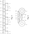
- friction layer material pads 8 extend. These pads 8 are integrally connected via the friction layer material extending though the through holes 9 with the friction layer 3 arranged on the support surface 10 of the elongate body 2. (see figure 3 )
- the support surface 10 of the elongate body 2 is provided with longitudinal grooves 11 to increase the contact surface between the elongate body 2 and the friction layer 3.
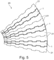
- FIG. 5 shows a schematic top view of a conveyor belt 20 according to the invention. Due to the tapering shape of the conveyor belt elements 1, 21, a curved conveyor belt 20 is provided. In some applications it is not required that each conveyor belt element 1 is provided with a friction layer. Therefore, with the conveyor belt 20 according to the invention, the conveyor belt elements 1 provided with friction layer and conveyor belt elements 21 without friction layer can be alternated.
Landscapes
- Engineering & Computer Science (AREA)
- Mechanical Engineering (AREA)
- Belt Conveyors (AREA)
Claims (6)
- Förderband, umfassend eine Vielzahl von benachbarten Förderbandelementen und eine Vielzahl von Stäben, die benachbarte Förderbandelemente verbinden, wobei jedes Bandelement umfasst:- einen länglichen Körper mit einer Stützfläche;- erste Vorsprünge, die auf einer ersten Seite des länglichen Körpers angeordnet sind und ausgerichtete Öffnungen aufweisen;- zweite Vorsprünge, die auf einer zweiten Seite gegenüber der ersten Seite angeordnet sind und ausgerichtete Öffnungen aufweisen,wobei die ersten Vorsprünge mit zweiten Vorsprüngen eines benachbarten Bandelements ineinandergreifen und sich ein Verbindungsstab durch die Öffnungen der ineinandergreifenden ersten und zweiten Vorsprünge erstreckt undwobei mindestens einige der Bandelemente weiter eine Reibungsschicht umfassen, die auf der Stützfläche angeordnet ist,wobei die Stützfläche mit einer Vielzahl von Durchgangslöchern, die sich von der Stützfläche zur gegenüberliegenden Oberfläche des länglichen Körpers erstrecken, versehen ist und wobei sich das Reibungsschichtmaterial durch die Durchgangslöcher und mindestens teilweise über die gegenüberliegende Oberfläche des länglichen Körpers erstreckt, um Verankerungselemente für die Reibungsschicht bereitzustellen,dadurch gekennzeichnet, dassder längliche Körper von einem Längsende zum anderen Längsende linear breiter wird, wobei sich das Reibungsschichtmaterial, das sich durch ein Paar Durchgangslöcher erstreckt, über ein Reibungsschichtmaterial, das sich über die gegenüberliegende Oberfläche des länglichen Körpers und zwischen dem Paar Durchgangslöcher erstreckt, miteinander verbunden ist.
- Förderband nach Anspruch 1, wobei jedes Paar Durchgangslöcher an entweder einem ersten Vorsprung oder einem zweiten Vorsprung ausgerichtet ist.
- Förderband nach einem der vorstehenden Ansprüche, wobei die Stützfläche mit einer Anzahl länglicher Nuten, die sich in Längsrichtung des Körpers erstrecken, versehen ist, um einen vergrößerten Oberflächenbereich bereitzustellen, an dem die Reibungsschicht haften kann.
- Förderband nach einem der vorstehenden Ansprüche, wobei das Reibungsschichtmaterial Polyurethan ist.
- Förderband nach einem der vorstehenden Ansprüche, wobei der längliche Körper aus Polyamid ist.
- Förderband nach einem der vorstehenden Ansprüche, wobei der längliche Körper und die Reibungsschicht durch Zweikomponentenspritzgießen aufeinander angeordnet sind.
Priority Applications (1)
| Application Number | Priority Date | Filing Date | Title |
|---|---|---|---|
| EP18162488.3A EP3543178B1 (de) | 2018-03-19 | 2018-03-19 | Förderband |
Applications Claiming Priority (1)
| Application Number | Priority Date | Filing Date | Title |
|---|---|---|---|
| EP18162488.3A EP3543178B1 (de) | 2018-03-19 | 2018-03-19 | Förderband |
Publications (3)
| Publication Number | Publication Date |
|---|---|
| EP3543178A1 EP3543178A1 (de) | 2019-09-25 |
| EP3543178B1 true EP3543178B1 (de) | 2023-06-07 |
| EP3543178C0 EP3543178C0 (de) | 2023-06-07 |
Family
ID=61691735
Family Applications (1)
| Application Number | Title | Priority Date | Filing Date |
|---|---|---|---|
| EP18162488.3A Active EP3543178B1 (de) | 2018-03-19 | 2018-03-19 | Förderband |
Country Status (1)
| Country | Link |
|---|---|
| EP (1) | EP3543178B1 (de) |
Families Citing this family (2)
| Publication number | Priority date | Publication date | Assignee | Title |
|---|---|---|---|---|
| DK181200B1 (en) * | 2021-07-15 | 2023-04-26 | Ammeraal Beltech Modular As | Conveyor belt system with fixed radius |
| IT202200014914A1 (it) * | 2022-07-15 | 2024-01-15 | Regina Catene Calibrate Spa | Modulo di tappeto trasportatore modulare curvilineo a raggio fisso e corrispondente tappeto. |
Family Cites Families (4)
| Publication number | Priority date | Publication date | Assignee | Title |
|---|---|---|---|---|
| US5921379A (en) * | 1996-01-23 | 1999-07-13 | The Laitram Corporation | Modular conveyor belt suitable for following straight or curved paths |
| WO1998014396A1 (de) * | 1996-10-03 | 1998-04-09 | Dieter Zimmermann | Aufstiegshilfevorrichtung |
| ES2253655T3 (es) * | 2002-10-11 | 2006-06-01 | Habasit Ag | Modulos de cinta transportadora con superficie de alta friccion. |
| DK2605984T3 (en) | 2010-08-19 | 2016-08-01 | Laitram Llc | A conveyor belt module of the two materials |
-
2018
- 2018-03-19 EP EP18162488.3A patent/EP3543178B1/de active Active
Also Published As
| Publication number | Publication date |
|---|---|
| EP3543178A1 (de) | 2019-09-25 |
| EP3543178C0 (de) | 2023-06-07 |
Similar Documents
| Publication | Publication Date | Title |
|---|---|---|
| US6811021B1 (en) | Plastic conveyor belt modules with unitary sideguards | |
| EP2326579B1 (de) | Filmscharnier-förderband | |
| EP0654426B1 (de) | Kunststoffförderband hoher Reibung mit Modulargliedern aus zwei integrierten Kunststoffen | |
| US6695135B1 (en) | Flexible flight modules in modular plastic conveyor belts | |
| US6382404B1 (en) | Corrugated flight module | |
| EP1890951B1 (de) | Modulare förderbänder und befestigungen | |
| EP3543178B1 (de) | Förderband | |
| WO2009000096A1 (en) | Conveyor belt module with high friction conveying surface | |
| SI21135A (sl) | Nakladalni člen | |
| US8020693B2 (en) | Belt link with half the surface inclined | |
| CA2513912A1 (en) | Non-slip conveyor and method for producing same | |
| EP3131839B1 (de) | Modul für ein förderband mit texturierter oberseite | |
| EP1712813B1 (de) | Flachriemen | |
| EP0916598A1 (de) | Kettenförderer zum Fördern von Produkten entlang einer bestimmten Achse | |
| WO2000066452A1 (en) | Friction tier sheet and method for producing the same | |
| CA2973599C (en) | Conveyor belt module with stepped hinge passageway | |
| IT202100003896U1 (it) | Tappeto di convogliamento a maglie articolate provvisto di sfere di rotolamento | |
| IT202000023095A1 (it) | Tappeto di convogliamento a maglie articolate provvisto di sfere di rotolamento | |
| MXPA06005080A (es) | Modulos de plastico de banda transportadora que comprenden protecciones laterles |
Legal Events
| Date | Code | Title | Description |
|---|---|---|---|
| PUAI | Public reference made under article 153(3) epc to a published international application that has entered the european phase |
Free format text: ORIGINAL CODE: 0009012 |
|
| STAA | Information on the status of an ep patent application or granted ep patent |
Free format text: STATUS: THE APPLICATION HAS BEEN PUBLISHED |
|
| AK | Designated contracting states |
Kind code of ref document: A1 Designated state(s): AL AT BE BG CH CY CZ DE DK EE ES FI FR GB GR HR HU IE IS IT LI LT LU LV MC MK MT NL NO PL PT RO RS SE SI SK SM TR |
|
| AX | Request for extension of the european patent |
Extension state: BA ME |
|
| STAA | Information on the status of an ep patent application or granted ep patent |
Free format text: STATUS: REQUEST FOR EXAMINATION WAS MADE |
|
| RBV | Designated contracting states (corrected) |
Designated state(s): AL AT BE BG CH CY CZ DE DK EE ES FI FR GB GR HR HU IE IS IT LI LT LU LV MC MK MT NL NO PL PT RO RS SE SI SK SM TR |
|
| 17P | Request for examination filed |
Effective date: 20200325 |
|
| GRAP | Despatch of communication of intention to grant a patent |
Free format text: ORIGINAL CODE: EPIDOSNIGR1 |
|
| STAA | Information on the status of an ep patent application or granted ep patent |
Free format text: STATUS: GRANT OF PATENT IS INTENDED |
|
| RIC1 | Information provided on ipc code assigned before grant |
Ipc: B65G 17/08 20060101AFI20221020BHEP |
|
| INTG | Intention to grant announced |
Effective date: 20221114 |
|
| GRAS | Grant fee paid |
Free format text: ORIGINAL CODE: EPIDOSNIGR3 |
|
| GRAA | (expected) grant |
Free format text: ORIGINAL CODE: 0009210 |
|
| STAA | Information on the status of an ep patent application or granted ep patent |
Free format text: STATUS: THE PATENT HAS BEEN GRANTED |
|
| AK | Designated contracting states |
Kind code of ref document: B1 Designated state(s): AL AT BE BG CH CY CZ DE DK EE ES FI FR GB GR HR HU IE IS IT LI LT LU LV MC MK MT NL NO PL PT RO RS SE SI SK SM TR |
|
| REG | Reference to a national code |
Ref country code: GB Ref legal event code: FG4D |
|
| REG | Reference to a national code |
Ref country code: CH Ref legal event code: EP Ref country code: AT Ref legal event code: REF Ref document number: 1574435 Country of ref document: AT Kind code of ref document: T Effective date: 20230615 Ref country code: DE Ref legal event code: R096 Ref document number: 602018050671 Country of ref document: DE |
|
| U01 | Request for unitary effect filed |
Effective date: 20230704 |
|
| U07 | Unitary effect registered |
Designated state(s): AT BE BG DE DK EE FI FR IT LT LU LV MT NL PT SE SI Effective date: 20230713 |
|
| REG | Reference to a national code |
Ref country code: LT Ref legal event code: MG9D |
|
| PG25 | Lapsed in a contracting state [announced via postgrant information from national office to epo] |
Ref country code: NO Free format text: LAPSE BECAUSE OF FAILURE TO SUBMIT A TRANSLATION OF THE DESCRIPTION OR TO PAY THE FEE WITHIN THE PRESCRIBED TIME-LIMIT Effective date: 20230907 Ref country code: ES Free format text: LAPSE BECAUSE OF FAILURE TO SUBMIT A TRANSLATION OF THE DESCRIPTION OR TO PAY THE FEE WITHIN THE PRESCRIBED TIME-LIMIT Effective date: 20230607 |
|
| PG25 | Lapsed in a contracting state [announced via postgrant information from national office to epo] |
Ref country code: RS Free format text: LAPSE BECAUSE OF FAILURE TO SUBMIT A TRANSLATION OF THE DESCRIPTION OR TO PAY THE FEE WITHIN THE PRESCRIBED TIME-LIMIT Effective date: 20230607 Ref country code: HR Free format text: LAPSE BECAUSE OF FAILURE TO SUBMIT A TRANSLATION OF THE DESCRIPTION OR TO PAY THE FEE WITHIN THE PRESCRIBED TIME-LIMIT Effective date: 20230607 Ref country code: GR Free format text: LAPSE BECAUSE OF FAILURE TO SUBMIT A TRANSLATION OF THE DESCRIPTION OR TO PAY THE FEE WITHIN THE PRESCRIBED TIME-LIMIT Effective date: 20230908 |
|
| PG25 | Lapsed in a contracting state [announced via postgrant information from national office to epo] |
Ref country code: SK Free format text: LAPSE BECAUSE OF FAILURE TO SUBMIT A TRANSLATION OF THE DESCRIPTION OR TO PAY THE FEE WITHIN THE PRESCRIBED TIME-LIMIT Effective date: 20230607 |
|
| PG25 | Lapsed in a contracting state [announced via postgrant information from national office to epo] |
Ref country code: IS Free format text: LAPSE BECAUSE OF FAILURE TO SUBMIT A TRANSLATION OF THE DESCRIPTION OR TO PAY THE FEE WITHIN THE PRESCRIBED TIME-LIMIT Effective date: 20231007 |
|
| PG25 | Lapsed in a contracting state [announced via postgrant information from national office to epo] |
Ref country code: SM Free format text: LAPSE BECAUSE OF FAILURE TO SUBMIT A TRANSLATION OF THE DESCRIPTION OR TO PAY THE FEE WITHIN THE PRESCRIBED TIME-LIMIT Effective date: 20230607 Ref country code: SK Free format text: LAPSE BECAUSE OF FAILURE TO SUBMIT A TRANSLATION OF THE DESCRIPTION OR TO PAY THE FEE WITHIN THE PRESCRIBED TIME-LIMIT Effective date: 20230607 Ref country code: RO Free format text: LAPSE BECAUSE OF FAILURE TO SUBMIT A TRANSLATION OF THE DESCRIPTION OR TO PAY THE FEE WITHIN THE PRESCRIBED TIME-LIMIT Effective date: 20230607 Ref country code: IS Free format text: LAPSE BECAUSE OF FAILURE TO SUBMIT A TRANSLATION OF THE DESCRIPTION OR TO PAY THE FEE WITHIN THE PRESCRIBED TIME-LIMIT Effective date: 20231007 Ref country code: CZ Free format text: LAPSE BECAUSE OF FAILURE TO SUBMIT A TRANSLATION OF THE DESCRIPTION OR TO PAY THE FEE WITHIN THE PRESCRIBED TIME-LIMIT Effective date: 20230607 |
|
| PG25 | Lapsed in a contracting state [announced via postgrant information from national office to epo] |
Ref country code: PL Free format text: LAPSE BECAUSE OF FAILURE TO SUBMIT A TRANSLATION OF THE DESCRIPTION OR TO PAY THE FEE WITHIN THE PRESCRIBED TIME-LIMIT Effective date: 20230607 |
|
| REG | Reference to a national code |
Ref country code: DE Ref legal event code: R097 Ref document number: 602018050671 Country of ref document: DE |
|
| PLBE | No opposition filed within time limit |
Free format text: ORIGINAL CODE: 0009261 |
|
| STAA | Information on the status of an ep patent application or granted ep patent |
Free format text: STATUS: NO OPPOSITION FILED WITHIN TIME LIMIT |
|
| U20 | Renewal fee for the european patent with unitary effect paid |
Year of fee payment: 7 Effective date: 20240311 |
|
| 26N | No opposition filed |
Effective date: 20240308 |
|
| PG25 | Lapsed in a contracting state [announced via postgrant information from national office to epo] |
Ref country code: MC Free format text: LAPSE BECAUSE OF FAILURE TO SUBMIT A TRANSLATION OF THE DESCRIPTION OR TO PAY THE FEE WITHIN THE PRESCRIBED TIME-LIMIT Effective date: 20230607 |
|
| PG25 | Lapsed in a contracting state [announced via postgrant information from national office to epo] |
Ref country code: MC Free format text: LAPSE BECAUSE OF FAILURE TO SUBMIT A TRANSLATION OF THE DESCRIPTION OR TO PAY THE FEE WITHIN THE PRESCRIBED TIME-LIMIT Effective date: 20230607 |
|
| PG25 | Lapsed in a contracting state [announced via postgrant information from national office to epo] |
Ref country code: IE Free format text: LAPSE BECAUSE OF NON-PAYMENT OF DUE FEES Effective date: 20240319 |
|
| PG25 | Lapsed in a contracting state [announced via postgrant information from national office to epo] |
Ref country code: IE Free format text: LAPSE BECAUSE OF NON-PAYMENT OF DUE FEES Effective date: 20240319 |
|
| U20 | Renewal fee for the european patent with unitary effect paid |
Year of fee payment: 8 Effective date: 20250317 |
|
| PGFP | Annual fee paid to national office [announced via postgrant information from national office to epo] |
Ref country code: CH Payment date: 20250401 Year of fee payment: 8 |
|
| PG25 | Lapsed in a contracting state [announced via postgrant information from national office to epo] |
Ref country code: CY Free format text: LAPSE BECAUSE OF FAILURE TO SUBMIT A TRANSLATION OF THE DESCRIPTION OR TO PAY THE FEE WITHIN THE PRESCRIBED TIME-LIMIT; INVALID AB INITIO Effective date: 20180319 |
|
| PG25 | Lapsed in a contracting state [announced via postgrant information from national office to epo] |
Ref country code: HU Free format text: LAPSE BECAUSE OF FAILURE TO SUBMIT A TRANSLATION OF THE DESCRIPTION OR TO PAY THE FEE WITHIN THE PRESCRIBED TIME-LIMIT; INVALID AB INITIO Effective date: 20180319 |
|
| PG25 | Lapsed in a contracting state [announced via postgrant information from national office to epo] |
Ref country code: TR Free format text: LAPSE BECAUSE OF FAILURE TO SUBMIT A TRANSLATION OF THE DESCRIPTION OR TO PAY THE FEE WITHIN THE PRESCRIBED TIME-LIMIT Effective date: 20230607 |
|
| REG | Reference to a national code |
Ref country code: CH Ref legal event code: U11 Free format text: ST27 STATUS EVENT CODE: U-0-0-U10-U11 (AS PROVIDED BY THE NATIONAL OFFICE) Effective date: 20260401 |
|
| PGFP | Annual fee paid to national office [announced via postgrant information from national office to epo] |
Ref country code: GB Payment date: 20260317 Year of fee payment: 9 |
|
| U20 | Renewal fee for the european patent with unitary effect paid |
Year of fee payment: 9 Effective date: 20260311 |