EP3544462B1 - Fermeture par contact - Google Patents
Fermeture par contact Download PDFInfo
- Publication number
- EP3544462B1 EP3544462B1 EP17794331.3A EP17794331A EP3544462B1 EP 3544462 B1 EP3544462 B1 EP 3544462B1 EP 17794331 A EP17794331 A EP 17794331A EP 3544462 B1 EP3544462 B1 EP 3544462B1
- Authority
- EP
- European Patent Office
- Prior art keywords
- fibers
- stems
- brush
- resin
- base
- Prior art date
- Legal status (The legal status is an assumption and is not a legal conclusion. Google has not performed a legal analysis and makes no representation as to the accuracy of the status listed.)
- Active
Links
Images




Classifications
-
- A—HUMAN NECESSITIES
- A44—HABERDASHERY; JEWELLERY
- A44B—BUTTONS, PINS, BUCKLES, SLIDE FASTENERS, OR THE LIKE
- A44B18/00—Fasteners of the touch-and-close type; Making such fasteners
- A44B18/0003—Fastener constructions
- A44B18/0015—Male or hook elements
-
- A—HUMAN NECESSITIES
- A44—HABERDASHERY; JEWELLERY
- A44B—BUTTONS, PINS, BUCKLES, SLIDE FASTENERS, OR THE LIKE
- A44B18/00—Fasteners of the touch-and-close type; Making such fasteners
- A44B18/0046—Fasteners made integrally of plastics
- A44B18/0061—Male or hook elements
- A44B18/0065—Male or hook elements of a mushroom type
-
- B—PERFORMING OPERATIONS; TRANSPORTING
- B29—WORKING OF PLASTICS; WORKING OF SUBSTANCES IN A PLASTIC STATE IN GENERAL
- B29C—SHAPING OR JOINING OF PLASTICS; SHAPING OF MATERIAL IN A PLASTIC STATE, NOT OTHERWISE PROVIDED FOR; AFTER-TREATMENT OF THE SHAPED PRODUCTS, e.g. REPAIRING
- B29C65/00—Joining or sealing of preformed parts, e.g. welding of plastics materials; Apparatus therefor
- B29C65/02—Joining or sealing of preformed parts, e.g. welding of plastics materials; Apparatus therefor by heating, with or without pressure
-
- B—PERFORMING OPERATIONS; TRANSPORTING
- B29—WORKING OF PLASTICS; WORKING OF SUBSTANCES IN A PLASTIC STATE IN GENERAL
- B29C—SHAPING OR JOINING OF PLASTICS; SHAPING OF MATERIAL IN A PLASTIC STATE, NOT OTHERWISE PROVIDED FOR; AFTER-TREATMENT OF THE SHAPED PRODUCTS, e.g. REPAIRING
- B29C65/00—Joining or sealing of preformed parts, e.g. welding of plastics materials; Apparatus therefor
- B29C65/78—Means for handling the parts to be joined, e.g. for making containers or hollow articles, e.g. means for handling sheets, plates, web-like materials, tubular articles, hollow articles or elements to be joined therewith; Means for discharging the joined articles from the joining apparatus
- B29C65/7802—Positioning the parts to be joined, e.g. aligning, indexing or centring
-
- B—PERFORMING OPERATIONS; TRANSPORTING
- B29—WORKING OF PLASTICS; WORKING OF SUBSTANCES IN A PLASTIC STATE IN GENERAL
- B29C—SHAPING OR JOINING OF PLASTICS; SHAPING OF MATERIAL IN A PLASTIC STATE, NOT OTHERWISE PROVIDED FOR; AFTER-TREATMENT OF THE SHAPED PRODUCTS, e.g. REPAIRING
- B29C66/00—General aspects of processes or apparatus for joining preformed parts
- B29C66/69—General aspects of joining filaments
-
- B—PERFORMING OPERATIONS; TRANSPORTING
- B29—WORKING OF PLASTICS; WORKING OF SUBSTANCES IN A PLASTIC STATE IN GENERAL
- B29L—INDEXING SCHEME ASSOCIATED WITH SUBCLASS B29C, RELATING TO PARTICULAR ARTICLES
- B29L2031/00—Other particular articles
- B29L2031/727—Fastening elements
- B29L2031/729—Hook and loop-type fasteners
Definitions
- This invention relates to touch fasteners, such as those with discrete male fastener elements configured to releasably engage a field of fibers, and to methods of forming such touch fasteners.
- Touch fastener products have a field of small hooking members, also known as fastening elements, that can engage fibers, such as loops, to hold two things together.
- small hooking members also known as fastening elements
- fastening elements that can engage fibers, such as loops, to hold two things together.
- Early male touch fastener products were formed by weaving loops of drawn filament, stabilizing the filament loops and then cutting one side of each loop to form a hook. Later, methods of molding very small male fastening elements were developed, resulting in arrays of hooking members extending from a sheet of resin.
- Some male fastening elements are molded to have an engageable head at the end of a molded stem. For example, J-hooks and palm-tree style hooks may be molded in closed cavities, or formed by cutting and stretching an extruded rail.
- Some other male fastening elements are formed by molding straight stems extending from a sheet of resin, and then deforming the ends of the stems to form heads. Fastening elements with heads that overhang their stems on essentially all sides of the stem are called mushrooms or mushroom hooks. While molding hooks or precursor stems can be very cost-effective, there are practical limits to the shapes and sizes of features that can be readily molded at high speeds.
- WO 2012/018879 describes touch fastener products that are made by distributing a multiplicity of discrete fastening bits over a support surface and fixing the distributed bits to the support surface, such as by an adhesive.
- Each bit has opposite side surfaces forming boundaries of surfaces defining projections extending in different directions from the fastening bits, at least one of the opposite side surfaces being non-planar, and each projection has an overhanging head.
- each bit is oriented with at least one of its projection heads raised from the support surface to releasably engage fibers.
- Bits are made by pelletizing shaped rails.
- FR 2786372 describes a hooked pile fastener has a sheet of plastics with a fused base.
- a layer of fabric on the base has male filaments with enlarged head sections.
- the fingers are formed of filaments embedded at their lower ends in the base sheet to form a mesh with raised sections forming curved heads.
- US 7,465,366 describes a sheet-form loop product that includes a flexible paper substrate and a layer of staple fibers disposed on a first side of the substrate, exposed loops of the fibers extending from holes through the substrate to a second side of the substrate, with bases of the loops being anchored on the first side of the substrate.
- the loops can be fastening loops.
- the product is formed by needling the fibers through the paper and then bonding the fibers.
- a touch fastener product has a base with a side surface, and a multiplicity of fastening elements extending from the side surface of the base.
- the fastening elements each have a non-tapered stem of resin extending from the side surface of the base to a head that overhangs sides of the stem for retaining fibers of a mating fastener product.
- the stems extend at different angles from the base and bases of the stems are secured to the side surface of the base at weld points in which resin of each stem is solidified in a weld with resin of the base side surface.
- a longitudinal axis of one stem extends at one angle to the base, while the same longitudinal axis of another stem extends at a different angle, etc.
- the stems extend from the base with a pseudo-random arrangement of angles and positions.
- the base side surface is formed by a resin film.
- the film and stems are of similar thickness.
- the film may have a second side surface opposite the side surface to which the bases of the stems are secured, the second side surface being exposed on a back side of the base.
- the product consists essentially of a film (as the base) and the fastening elements.
- the heads overhang all sides of stems.
- the fastening elements of such products can be considered mushroom-type fastening elements.
- the stems are in the form of cylindrical tubes, or are otherwise hollow.
- the heads define openings into the hollow stems.
- the stems have longitudinal seams extending along their length, such as extrusion seams.
- the heads in some such products have perimeters defining apices corresponding to the longitudinal seams of the stems.
- the stems each have three extrusion seams and the heads have perimeters shaped as Reuleaux triangles.
- the stems are very long and slender, having, for example, a length-to-thickness ratio of between 10 and 60 (or in some cases, between 20 and 50).
- the stems have a nominal stem length of at least 1.5 mm and/or a nominal thickness of less than about 0.2 mm.
- the stems are of differing nominal thicknesses.
- the stems may include one set of stems of relatively low thickness and another of relatively high thickness.
- the stems may be of longitudinally drawn resin, which can help to facilitate the desired free formation of heads under proper conditions.
- the stems may be of a pseudo-random distribution across the base. We discuss below what is meant by pseudo-random.
- the stems need not be each accurately positioned in order to form a useful fastening.
- some or all of the heads each have a bulb at a base of the head.
- the welds are each in the form of a solidified puddle of resin disposed above the side surface, wherein the side surface is generally planar.
- Another aspect of the invention features a method of making a fastener product, including orienting a number of extruded resin fibers in a common direction, and engaging an exposed end of each fiber with a side of a resin sheet extending normal to the common direction.
- the engaged ends of the fibers are permanently secured to the resin sheet by welding resin of the fibers to resin of the sheet.
- Engageable heads are formed on ends of the fibers opposite the secured ends.
- the resin sheet comprises a film forming the side of the sheet, or essentially consists of such a film, or is a film.
- permanently securing the engaged ends of the fibers to the resin sheet forms welds extending beyond sides of the fibers, such that the welds have a lateral extent, at the side of the resin film, at least twice a nominal thickness of the secured fibers.
- permanently securing the engaged ends of the fibers forms holes in the resin sheet or film.
- orienting the extruded hollow resin fibers comprises holding the fibers between and parallel to bristles of a brush, with the exposed ends of the fibers extending at or beyond distal ends of the brush bristles and positioned within a distance of a common datum, the distance being less than 20 percent of an average length of the fibers.
- the datum may be a plane spaced a determined distance from the distal ends of the brush bristles.
- Orienting the extruded hollow resin fibers may include needling the fibers into the brush and may include, before needling the fibers, supporting the fibers on the distal ends of the brush bristles as an incoherent batt of staple fibers.
- Orienting the extruded hollow resin fibers may involve, after needling the fibers, removing unoriented fibers from the brush while holding the oriented fibers between the brush bristles.
- Orienting the extruded hollow resin fibers may involve, while holding the fibers between and parallel to the brush bristles, pressing the exposed ends of the fibers toward the brush to position the exposed ends with respect to the datum.
- the brush bristles have a free length to thickness ratio of between 10 and 100.
- 'free length' is the overall length of the bristle from where it is secured in the brush body to its free end.
- the brush bristles are sufficiently densely packed that the oriented fibers are held in their oriented position by adjacent bristles.
- the method is preferably performed as a continuous process, the brush being in the form of a recirculating belt that moves sequentially through a fiber laying station, a needling station, a securing station, a product removing station, and a brush cleaning station in which unsecured fibers are removed from between the brush bristles before the belt returns to the fiber laying station.
- engaging the exposed ends of the fibers involves supporting the carrier sheet on the exposed ends while the fibers are held between the brush bristles.
- permanently securing the engaged ends of the fibers to the carrier sheet involves heating the engaged ends of the fibers with heat applied through the carrier sheet, or heating the exposed ends of the fibers before engaging the exposed ends of the fibers with the side of the carrier sheet.
- forming the engageable heads involves heating the distal ends to cause resin of the distal ends to deform into heads that overhang sides of the fibers.
- the distal ends may be heated with a non-contact heat source, for example.
- the heads may be formed such that the head defines an overhang about its entire perimeter.
- the engageable heads, as formed define openings into the hollow fibers.
- Forming the engageable heads may include heating the distal ends of the hollow fibers to cause resin of the distal ends to roll outwardly and downwardly to overhang the fibers.
- the extruded resin fibers each have one or more extrusion seams extending longitudinally along the fiber, and the formed engageable heads have perimeters defining a number of perimeter apices corresponding to a quantity of the extrusion seams of the fibers.
- the extruded resin fibers may each have three extrusion seams, with the head perimeters each defining three perimeter apices.
- the engageable heads define openings into the hollow fibers
- the openings defined by the engageable heads may define a number of opening apices corresponding to the quantity of the extrusion seams of the fibers.
- the fibers are of different thicknesses and forming the engageable heads includes forming relatively larger heads on relatively thicker fibers, and forming relatively smaller heads on relatively thinner fibers.
- the fibers, as oriented, are straight, uncrimped, staple fibers of length between 4 and 10 mm.
- the staple fibers may have a nominal thickness of between 50 and 250 microns, and/or a length to thickness ratio of between 10 and 60 (or between 20 and 50).
- the sheet (or film) has a nominal thickness between 0.3 and 2.5 times a nominal thickness of the fibers.
- the methods taught herein may be employed to make particularly thin and flexible fastener elements able to penetrate into dense fiber layers and flex to retain engaged fibers.
- the manufacturing method may be performed at high speeds to produce a product that is very material-efficient, and may be readily adapted to make touch fastener products of different properties.
- the methods tend to produce fields of touch fastener elements having a desirable variability in height and direction, and can be practiced to form stable connections between staple stem fibers and an inexpensive carrier film, for example, by direct welding rather than requiring a separate adhesive material.
- the methods, and resulting structures are also not subject to many of the limitations of high speed molding or extrusion.
- a touch fastener product 10 has a base 12 with a side surface 14 formed by a resin film.
- a multiplicity of fastening elements 16 extend from the side surface of the base, each having a non-tapered stem 18 of resin extending from the side surface of the base to a head 20 that overhangs sides of the stem, for retaining fibers of a mating fastener product (not shown).
- the side surface 14 of the base in this example has a non-smooth topography, but other examples have smoother topography, as shown in other figures.
- the stems 18 extend generally perpendicularly to the base, in that they are predominantly upright.
- the stems extend at different angles, with some essentially vertical and others leaning, and still others with noticeable bends.
- the stems have a particularly high length to thickness ratio, meaning that they are relatively tall and slender, and are of generally constant cross-section, meaning that the cross-section of the stem stays generally constant over its length and not, for example, tapering in thickness.
- Heads 20 are generally disk-shaped, overhanging all sides of their associated stems, but are not of identical size and shape.
- the stems are not arranged in an ordered pattern or array, but are of a pseudo-random distribution. By 'pseudo-random' we mean that the distribution is apparently random to visual observation. This does not preclude slight patterning as a residual effect of patterning, such as by needling, but distinguishes structural patterning such as weave or knit patterns or repetitive molding patterns.
- a typical head 20 has an outer shape approximating a Reuleaux triangle, with three generally curved sides 22 joined at three generally equidistant curved apices 24.
- the upper (outer) surface of the head is gently curved and convex about a central aperture 26 open to the interior of the stem 18, which is hollow.
- FIG. 2A Another example of a head 20 is shown in Fig. 2A , in which the shape of the central aperture 26 is more evident, as is the outer shape of the overall head.
- the overall width of the head, for size reference is about 0.5 mm, or about 2.5 times the thickness of the underlying stem.
- the stems 18 have bases 28 that are secured to the side surface of the film at weld points 30 in which resin of each stem is solidified in a weld with resin of the film 32. How this welding is accomplished with such thin stems and thin film is discussed in more detail below.
- the weld is in the form of a solidified puddle of resin disposed above the generally planar film surface, as seen in Fig. 3 . In other instances the weld forms less of a discrete puddle above the film, as in the example shown in Fig. 3A .
- the stems each have a length 'L', measured along the stem from the side surface of the base to an underside of the head, and an overall lateral thickness 'T', measured perpendicular to the stem.
- the stems have a length to thickness ratio (L/T) of at least 10, or between 10 and 60.
- the stems shown in Fig. 1 for example, have a typical length of about 4.2 mm and a nominal thickness of about 0.15 mm, resulting in an L/T ratio of around 30.
- Fig. 3 also shows that in some cases, holes 33 may be formed in the film during the formation of the product.
- each stem 18 is tubular and hollow over a majority of its length, with a generally cylindrical outer surface.
- the tubular stems each have extrusion seams 34 extending longitudinally along the stem.
- the stems each have three generally equidistant seams 34, and the number of seams is believed to be determinative of the number of sides and apices of the resulting heads 20, with the number of apices corresponding to the number of seams. This is evident, for example, in Fig. 2A , in which the three seams 34 are visible at corresponding corners formed in the central aperture 26 of the head. These seams 34 and corresponding aperture corners are circumferentially aligned with the three apices of the head. As will be discussed below, the free-form formation of the heads from resin of the seamed stems is believed to account for this phenomenon.
- This can also be called a 'melt buckling' effect, the result of which is to produce a base 28 having an expanded footprint on the film, for increased weld area and better securement of the stems to the film.
- Evidence of the melt buckling can be seen in the slight diameter fluctuations at some of the stem bases.
- at least many of the welds produced at the bases of the stems have a lateral extent, at the side of the resin film, of at least twice the nominal thickness of the stems themselves.
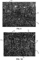
- stems 18 of this example have straight distal ends and are generally of the overall shape of drinking straws. As evident in Fig. 7 , these stems may be of different diameters. At least many extend to a similar, although not identical, height from base 12. The topography of the base is affected by portions of stems that have melted into the surface of the film as a result of the manufacturing process, described below.
- This example was produced needling fibers into a brush having bristles substantially longer than the staple fibers - in this case needling 6 mm fibers into a 20 mm deep brush.
- the precursor stems each have a defined and discrete bend, with the bends located at a generally common distance from the base.
- the bent stems are straight other than at the single bend, often near a midpoint of the length of the stem.
- the heading process can be conducted in many instances such that bent precursor stems are straightened in the process of forming the heads.
- This example was produced needling fibers into a brush having a bristle bed only about as deep as the length of the stable fibers - in this case, needling 6 mm fibers into a brush of only 6 mm long bristles.
- useful product was produced even needling fibers in such a way that the fiber did not align vertically over substantially its entire length within the brush before fusing to a backing.
- a machine 50 and process for producing the fastener product of the above-described figures features a continually moving brush apron 52 comprised of rigid brush segments 54 linked to form a continuous loop. Each segment carries a dense bed of upstanding flexible bristles extending from a rigid base. As shown, brush apron 52 is maintained to travel at a constant line speed along a linear path through various stations of the manufacturing process. In some embodiments, brush apron 52 has a nominal bristle density of about 2500 bristles per square inch (about 380 bristles per square centimeter).
- the bristles are each about 0.008 inch (0.2 millimeter) in diameter and about 6 millimeters long (although 20 mm long bristles have also been successfully used), with rounded tips.
- the bristles used to produce the products illustrated above are crimped, with a crimp period of about 5 mm and a crimp amplitude of about 0.5 mm.
- the bristles may be formed of any suitable material, for example 6/12 nylon. Suitable brushes may be purchased commercially and retrofitted onto supporting links. Generally, the brush apron moves at the desired line speed.
- a loose batt 56 of staple fibers 58 is air laid on the brush apron, such as from an air chute 60.
- the fibers, as laid on the velour brush apron, are randomly distributed and randomly oriented and form a batt of only about 200 grams per square meter (gsm).
- the staple fibers are uncrimped, hollow fibers, each having a nominal length of only about 6 mm, and are completely disconnected and loose in the batt.
- the batt 56 has virtually no strength or coherence in any direction because the fibers are not entangled or otherwise tethered.
- the batt is an "incoherent" layer of staple fibers, having little to no dimensional stability in any direction, and will pull apart under its own weight if attempted to be lifted from the brush apron at this stage.
- suitable fibers 58 are drawn and uncrimped fibers, 40 to 200 denier, of about 4 mm to 10 mm staple length, preferably hollow.
- polypropylene 70 dtex hollow fibers, cut to 6 mm length were obtained from IFG Asota of Linz, Austria, as an uncrimped variant of their product G40B2, cut to a 6 mm staple length.
- Such fibers are believed to be extruded from spinnerets having multiple curved orifices separated by thin walls, such that extrudate from the adjacent orifices join immediately after or during extrusion to form the seams.
- each spinneret would have three arc-shaped nozzle openings arranged in a circle.
- Envisioned modifications to alter the resulting structure of the fiber include altering the distance between adjacent nozzle openings, or altering the number of openings spaced about the perimeter to change the number of resulting seams.
- the shapes of the orifices may also be altered to create a fiber (stem) of non-circular outer circumference, or a different inner surface configuration, both to change the structural properties of the stems and to create different head shapes.
- Various synthetic fiber materials may be employed, understanding that formation of the heads is affected by the amount of residual draw or longitudinal strain in the fibers as laid on the brush apron.
- bicomponent fibers either of one resin sheathed with a second resin or of alternating longitudinal segments of two resins, either solid or hollow.
- the fibers 58 may be of different thicknesses or otherwise of different construction, but preferably all of the fibers are of drawn resin suitable for head formation, as discussed below, for efficient use of materials.
- Stem fibers with tenacity values, measured in accordance with test method ISO 5079, of at least 5 cN/tex are preferable, and fibers with a tenacity of at least 10 or more cN/tex (preferably even 15 or more cN/tex) are even more preferred in many instances.
- the higher the fiber tenacity the stronger the fastener element stem.
- the stems have relatively high strength so that they do not break when the fastener product is disengaged. Widespread stem breakage can deleteriously effect re-engagement of the fastener.
- fiber batt 56 in its incoherent state, is carried by brush apron 52 into a needling station 62, where the batt of fibers is repeatedly needle-punched.
- the needles may be guided through a stripper plate above the fibers, and draw fibers of the batt deep into the brush apron on the other side.
- batt 56 is supported directly on the bristles of brush apron 52 (as shown in Figs. 12A-12D ), which moves with the fibers through needling station 62.
- needling station 62 needles the batt with an overall penetration density of about 80 to 320 punches per square centimeter, using forked needles 68.
- needle beams are fitted with needle boards having a density of 7500 needles/meter.
- the needle loom was fitted with 36 gauge, 2.5 inch needles and cycled with a stroke frequency of 2100 strokes per minute.
- Figs. 12A through 12D sequentially illustrate the displacement of fibers deep into the brush apron by the needling process.
- the loose batt 56 of fibers is conveyed to the needling station by brush apron 52, with the individual fibers 58 of the batt carried directly on a bed of brush bristles 70 ( Fig. 12A ).
- a fork needle 68 enters the batt ( Fig. 12B )
- some individual fibers 58 will be captured in the cavity between the leading prongs of the forked end of the needle.
- needle 68 "punches" into the brush, these captured fibers 58 are drawn down with the needle into the bed of bristles 70.
- the penetrating needle 68 laterally displaces local brush bristles 70 as it intrudes upon brush apron 52.
- the captured fibers 58 are drawn deep into the brush and out of the batt.
- the needling depth can be somewhat greater than the staple fiber length and still produce useful product.
- an elliptical needling technique (such as described in U.S. Patent No. 7,465,366 ), or similar, can be used to reduce or eliminate relative movement between the batt and the penetrating needles.
- the needle boards can be populated with needles only in discrete regions, and the needling action paused while the material is indexed through the loom between adjacent loop regions. Effective pausing of the needling action can be accomplished by altering the penetration depth of the needles during needling, including to needling depths at which the needles do not penetrate the batt.
- Such needle looms are available from Autefa Solutions in Austria, for example.
- means can be implemented to selectively activate smaller banks of needles within the loom according to a control sequence that causes the banks to be activated only when and where fastener elements are desired.
- Lanes of fastener elements can be formed by a needle loom with lanes of needles separated by wide, needle-free lanes.
- this needling process drives a significant portion (generally, about 25 percent or more) of the fiber into the brush, leaving ends of individual fibers extending upward from between the brush bristles 70.
- Fig. 12D as a result of the needling fibers are left oriented in the vertical direction (normal to the batt), with at least one end 66 of each fiber exposed and positioned within a distance 'd' of datum 64.
- the distance 'd' is less than 20 percent of the average or nominal length of the staple fibers.
- the needling results in many fiber ends 66 being within 1 mm of a common datum above the surface of the brush.
- the result of the needling is that the nominal distance d1 that the fiber ends extend from the brush (represented by datum 64) is in some cases about 2 mm, such that the majority of each of the embedded fibers is primarily between the brush bristles 70. Prior to vacuuming the remaining fibers from the surface, the exposed ends may be difficult to see.
- a roller 72 that helps to further normalize the distance to which the fiber ends extend above the brush surface, further diminishing the distance d1 that datum 64 for is above the brush (see Fig. 12D ).
- datum elevation d1 is only about 0.3 mm, or even zero.
- a flat plate or flat belt laminator can be used to press the fibers further into the brush. After roller 72, any loose (excess) fibers are vacuumed from the brush surface, leaving essentially only those fibers that have been oriented vertically within the brush, generally with exposed ends extending a nominal distance (d1, Fig.
- vacuuming may remove 140 gsm of fiber, with another 10 gsm of fiber subsequently removed from the brush after removal of the product - meaning that only 1 ⁇ 4 of the original fiber mass (or 50 gsm, in this case) is incorporated into the final product.
- a film 74 is then introduced to the exposed fiber ends (and to the tops of the bristles if the fibers have been depressed to be fully within the brush) and the film fused to the exposed ends of the fibers. Immediately before introduction of the film, either or both of the film surface and the fiber ends are softened by heat from a radiant heater 76.
- pressure is applied to the fiber ends through the film, such as by a pressure belt 78 that travels with the brush apron to apply a desired, non-sliding pressure to the film for a desired dwell time, to effect the fusing.
- Belt 78 may be heated, such that heat is applied by the belt, through the film, to the fiber ends, either additionally, or as an alternative, to preheating the fiber ends and/or film. In any case, it is a combination of heat and pressure over time that causes the ends of the fibers to weld to the film.
- Belt 78 may be equipped with multiple sequential heating and cooling zones to affect different heating conditions as needed to effect the desired bonding, depending on thicknesses, speeds and materials, such as is taught in U.S.S.N. 14/725,420, filed May 29, 2015 .
- formation of the products shown in Figs. 1-4 required only a single pressure/heating cycle, using a heating plate of temperature of about 400 degrees F, pressed against the back of the film with a pressure of about 0.09 psi and held in place for about 1 second.
- holes see hole 33 in Fig. 3
- the film can partially fuse also to tips of the bristles, such that when the film is later removed small amounts of film material are removed from the surface, leaving divots or craters (such as craters 35 seen in Fig. 4 ). Such craters are not found to have any detrimental effect on the performance of the fastener product. Cratering may be reduced by lowering pressure and/or temperature of the fusing process, or by coating the bristle tips.
- Film 74 may be, for example, a 45 gsm, 0.05 mm thick film, such as of polypropylene if working with polypropylene fibers.
- the film and fibers are of the same base resin, to promote welding. We have found that this process can successfully fuse fiber ends to film even when the film is of the same thickness as, or even thinner than, the rather thin fibers. In the fusing process, there is evidence of melting of both the film and the fiber at the weld points.
- the precursor fastener product 102 (film and fused fibers) is removed from brush apron 52 via tension applied by a stripper roll 80, which pulls the oriented fibers from the bed brush bristles.
- the precursor product has a base formed predominantly of film but incorporating random portions of fiber that had remained on the brush surface, and a bunch of fibers fused to, and extending from, the base as shown in Figs. 7-10 .
- This precursor product is next transported to a heading station 82 featuring a heated platen 84 that applies radiant heat to the stem side of the product as it travels past the platen against a support 86, forming engageable heads on the distal ends of the fibers.
- a hot wire or hot knife may be employed, but as described below, the heating time and temperature can be varied by an appropriately shaped and positioned platen, to control the heading process.
- a 1000 degree F hot knife in the form of a foam cutter with a 15 cm blade, was moved past the product at a speed of about 2.5 cm/sec, just above the stems.
- the fastener product 10 can be spooled or otherwise processed, such as by direct lamination to a product surface, such as a non-woven diaper chassis.
- a product surface such as a non-woven diaper chassis.
- the film forming the base of the product remains non-porous to form a substantially impermeable product that can be subsequently processed using vacuum transport.
- Other materials can be bonded to the film, either as the fibers are fused or in a subsequent lamination process. Examples of such materials include other films, such as elastomeric or stretchable films, non-woven materials, and paper.
- a material other than film can be used to form the base of the product.
- a light non-woven material can be fused onto the exposed fiber ends to form a porous base from which the stems extend.
- the loose fibers of the batt are left on the brush surface and fused together (and to the exposed fiber ends) to form the product base.
- the brush segments are cleaned of any remain fiber at a cleaning station 88, in which hook rolls 90 agitate the brush surface in the presence of a cleaning air flow. Removed fibers may be recycled into the process.
- the heading process at heading station 82 takes advantage of the residual stresses in the extruded or spun fibers forming the stems.
- a first noticed effect is that fibers with a residual bend (such as those shown in Figs. 9 and 10 ) tend to straighten at the bend and stand more generally erect, as strain at the bend is relieved.
- the distal ends of the fibers or stems begin to deform.
- the deformation appears to progress as a rolling of the stem material outward and downward, such as one might imagine the rolling of an upper end of a sock down a leg, for example. This rolling motion appears to stabilize the head shape as the roll occurs about the entire circumference rather uniformly.
- the hollow fiber form can facilitate a faster and more uniform rolling, and it is believed that the apices forming in the head at the seams tend to help promote the width of the forming head, resulting in a structure suitable for releasable engagement of loops or other fibers.
- the heading process can also significantly shorten the stems, beyond the shortening necessarily occasioning the rolling of the heads themselves, as residual stresses in the stems are relaxed.
- the heading process can be controlled to produce a variety of different engageable head shapes, and that due to the varied positioning and nature of the stems there will be a range of head sizes and shapes across any given product.
- the stems may be of different thicknesses, producing correspondingly different head sizes and melting/rolling at different rates.
- longer application of heat can cause a swelling of the stems immediately below the heads, producing what can best be described as a bulb at the base of the head, as shown in Fig. 13 .
- This effect can be optimized for improved stem/head connection strength and stiffness, for example. Direct flame or hot air heating may be used as an alternative to a heated surface, if properly controlled.
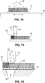
- Fig. 14 conceptually illustrates motivating discrete staple fibers into a brush segment 54 using vibration applied to the brush segment by a shaker table 90 that vibrates the brush segment laterally as the fibers are introduced to the surface of the brush.
- a vibration frequency in connection with the structural properties of the brush bristles, transient openings may be formed between bristles in order to receive fibers that penetrate farther into the brush and become vertically oriented between bristles as a result of the vibration.
- FIG. 15 conceptually illustrates ejecting fibers into the brush by means of a pneumatic nozzle 92 that orients the fibers vertically and drives them into the brush as the nozzle moves across the brush surface.
- the nozzle tip may be configured to engage and separate the bristle tips to facilitate fiber injection.
- the nozzle is connected both to a source of pressurized air flow and to a source of fibers, such that the fibers are entrained in a flow of air introduced to the nozzle.
- Fig. 16 conceptually illustrates pulling discrete staple fibers into a brush segment supported on a vacuum table 94.
- hopper 98 of loose fibers aligned with a vacuum port 96 in the table
- air is drawn from the hopper, between the brush bristles, through apertures in the base of the brush segment, and into the vacuum port 96, carrying fibers 58 from the hopper into the brush and orienting them vertically between the bristles.
- the lower end of hopper 98 may be configured to splay the bristles as the brush passes beneath, facilitating fiber placement.
Landscapes
- Engineering & Computer Science (AREA)
- Mechanical Engineering (AREA)
- Slide Fasteners, Snap Fasteners, And Hook Fasteners (AREA)
Claims (16)
- Produit de fixation par contact (10) comprenant
une base (12) ayant une surface latérale (14) ; et
une multiplicité d'éléments de fixation (16) s'étendant depuis la surface latérale (14) de la base (12), les éléments de fixation ayant chacun une tige non effilée (18) de résine s'étendant depuis la surface latérale de la base jusqu'à une tête (20) qui surplombe des côtés de la tige pour retenir des fibres d'un produit de fixation conjugué
dans lequel les tiges (18) s'étendent à des angles différents depuis la base (12) ; et dans lequel des bases (28) des tiges (18) sont fixées à la surface latérale (14) de la base (12) à des points de soudure (30), caractérisé en ce dans les points de soudure (30), la résine de chaque tige est solidifiée dans une soudure avec la résine de la surface latérale de base. - Produit de fixation par contact (10) de la revendication 1, dans lequel la surface latérale de base (14) est formée par un film de résine (32), en particulier dans lequel le film et les tiges (18) sont d'une épaisseur similaire et/ou dans lequel le film a une deuxième surface latérale à l'opposé de la surface latérale (14) à laquelle sont fixées les bases (28) des tiges, la deuxième surface latérale étant exposée sur un côté arrière de la base (12).
- Produit de fixation par contact (10) de l'une ou l'autre des revendications précédentes, dans lequel les têtes (20) surplombent tous les côtés de leurs tiges respectives (18).
- Produit de fixation par contact (10) de l'une quelconque des revendications précédentes, dans lequel les tiges (18) se présentent sous la forme de tubes cylindriques, et/ou dans lequel les tiges sont creuses, en partie dans lequel les têtes (20) définissent des ouvertures (26) à l'intérieur des tiges creuses (18), et éventuellement dans lequel les tiges (18) ont des jonctions longitudinales (34) s'étendant le long de leur longueur, en particulier dans lequel les têtes (20) ont des périmètres (22) définissant des sommets (24) correspondant aux jonctions longitudinales des tiges et/ou dans lequel les tiges ont chacune trois jonctions d'extrusion (34) et les têtes ont des périmètres façonnés comme des triangles de Reuleaux.
- Produit de fixation par contact (10) de l'une quelconque des revendications précédentes, dans lequel les tiges (18) ont un rapport longueur/épaisseur compris entre 10 et 60, en particulier entre 20 et 50, et/ou ont une longueur nominale de tige d'au moins 1,5 mm et/ou une épaisseur nominale de moins d'environ 0,2 mm.
- Produit de fixation par contact (10) de l'une quelconque des revendications précédentes, dans lequel les tiges (18) sont de différentes épaisseurs nominales, et/ou sont en résine étirée longitudinalement, et/ou sont d'une distribution pseudo-aléatoire sur toute la base (12).
- Produit de fixation par contact (10) de l'une quelconque des revendications précédentes, dans lequel au moins certaines des têtes (20) ont chacune un bulbe à une base de la tête.
- Produit de fixation par contact de la revendication 1, dans lequel les soudures sont chacune sous la forme d'un bain solidifié de résine disposé au-dessus de la surface latérale, la surface latérale étant généralement plane.
- Procédé de fabrication d'un produit de fixation (10), le procédé comprenant :l'orientation d'un nombre de fibres de résine extrudées (58) dans une direction commune ;l'engagement d'extrémités exposées (66) des fibres avec un côté d'une feuille de support (74) s'étendant perpendiculairement à la direction commune ;la fixation permanente des extrémités engagées (66) des fibres (58) à la feuille de support par soudage de la résine des fibres à la résine de la feuille de support ; etla formation de têtes engageables (20) sur des extrémités des fibres (58) à l'opposé des extrémités fixées (66).
- Procédé de la revendication 9, dans lequel les fibres extrudées (58) sont orientées avec une extrémité (66) de chaque fibre exposée et positionnée à moins d'une distance d'un repère commun (64), en particulier avec la distance inférieure à 20 pour cent d'une longueur moyenne des fibres.
- Procédé de la revendication 9 ou la revendication 10, dans lequel les fibres de résine extrudées (58) sont creuses, en particulier dans lequel les têtes engageables (20), telles que formées, définissent des ouvertures (26) à l'intérieur des fibres creuses (58).
- Procédé de l'une quelconque des revendications 9 à 11, dans lequel la feuille de support comprend un film (74, 32) définissant le côté (14) de la feuille de support, en particulier dans lequel la fixation permanente des extrémités engagées (66) des fibres (58) à la feuille de support forme des soudures (30) s'étendant au-delà de côtés des fibres, de telle sorte que les soudures ont une étendue latérale, au niveau du film, égale à au moins deux fois une épaisseur nominale des fibres fixées (58), en particulier dans lequel la fixation permanente des extrémités engagées des fibres à la feuille de support forme des trous (33) dans le film.
- Procédé de l'une quelconque des revendications 9 à 12, dans lequel l'orientation du nombre de fibres de résine extrudées (58) dans la direction commune comprend le maintien des fibres entre et parallèles à des crins (70) d'une brosse, avec les extrémités exposées (66) des fibres s'étendant jusqu'à et au-delà d'extrémités distales des crins de brosse (70), en particulier dans lequel l'orientation du nombre de fibres de résine extrudées dans la direction commune comprend l'aiguilletage des fibres à l'intérieur de la brosse, en particulier dans lequel l'orientation du nombre de fibres de résine extrudées dans la direction commune comprend, avant l'aiguilletage des fibres, le support des fibres sur les extrémités distales des crins de brosse sous la forme d'une natte incohérente (56) de fibres discontinues (58), et
le procédé étant éventuellement effectué sous la forme d'un procédé continu, la brosse comprenant un plateau de brosse de recirculation (52) qui se déplace successivement à travers un poste de pose de fibres, un poste d'aiguilletage (62), un poste de fixation, un poste de retrait de produit, et un poste de nettoyage de brosse (88) dans lequel des fibres non fixées (58) sont retirées d'entre les crins de brosse (70) avant que le plateau de brosse (52) retourne au poste de pose de fibres, et/ou dans lequel l'engagement des extrémités exposées (66) des fibres comprend le support de la feuille de support sur les extrémités exposées pendant que les fibres sont maintenues entre les crins de brosse. - Procédé de l'une quelconque des revendications 9 à 13, dans lequel la fixation permanente des extrémités engagées (66) des fibres (58) à la feuille de support comprend le chauffage des extrémités engagées des fibres avec de la chaleur appliquée à travers la feuille de support et/ou le chauffage des extrémités exposées des fibres avant l'engagement des extrémités exposées des fibres avec le côté (14) de la feuille de support.
- Procédé de l'une quelconque des revendications 9 à 14, dans lequel la formation des têtes engageables (20) comprend le chauffage d'extrémités distales des fibres creuses (58) pour faire rouler la résine des extrémités distales vers l'extérieur et vers le bas pour surplomber les fibres, en particulier dans lequel les fibres de résine extrudées (58) ont chacune une ou plusieurs jonctions d'extrusion (34) s'étendant longitudinalement le long de la fibre, et les têtes engageables formées ont des périmètres (22) définissant un nombre de sommets de périmètre (24) correspondant à une quantité des jonctions d'extrusion des fibres, en particulier dans lequel les fibres de résine extrudées (58) ont chacune trois jonctions d'extrusion et les périmètres de tête définissent chacun trois sommets de périmètre.
- Procédé de l'une quelconque des revendications 9 à 15, dans lequel, telles qu'orientées, les fibres (58) sont des fibres discontinues rectilignes, défrisées, de longueur comprise entre 4 et 10 mm, en particulier dans lequel les fibres discontinues ont une épaisseur nominale comprise entre 50 et 250 µm et/ou ont un rapport longueur/épaisseur compris entre 10 et 60, et/ou dans lequel la feuille de support a une épaisseur nominale comprise entre 0,3 et 2,5 fois une épaisseur nominale des fibres.
Applications Claiming Priority (3)
| Application Number | Priority Date | Filing Date | Title |
|---|---|---|---|
| US201662425710P | 2016-11-23 | 2016-11-23 | |
| US201662425691P | 2016-11-23 | 2016-11-23 | |
| PCT/EP2017/078405 WO2018095723A1 (fr) | 2016-11-23 | 2017-11-07 | Fermeture par contact |
Publications (2)
| Publication Number | Publication Date |
|---|---|
| EP3544462A1 EP3544462A1 (fr) | 2019-10-02 |
| EP3544462B1 true EP3544462B1 (fr) | 2021-01-06 |
Family
ID=60262937
Family Applications (1)
| Application Number | Title | Priority Date | Filing Date |
|---|---|---|---|
| EP17794331.3A Active EP3544462B1 (fr) | 2016-11-23 | 2017-11-07 | Fermeture par contact |
Country Status (4)
| Country | Link |
|---|---|
| US (1) | US10722003B2 (fr) |
| EP (1) | EP3544462B1 (fr) |
| CN (1) | CN110035674B (fr) |
| WO (1) | WO2018095723A1 (fr) |
Cited By (1)
| Publication number | Priority date | Publication date | Assignee | Title |
|---|---|---|---|---|
| DE102021000393A1 (de) | 2021-01-27 | 2022-07-28 | Gottlieb Binder Gmbh & Co. Kg | Befestigungseinrichtung nebst Verfahren zum Herstellen einer solchen Befestigungseinrichtung und ein mit einer solchen Befestigungseinrichtung hergestelltes Befestigungssystem |
Families Citing this family (4)
| Publication number | Priority date | Publication date | Assignee | Title |
|---|---|---|---|---|
| US10722003B2 (en) | 2016-11-23 | 2020-07-28 | Velcro BVBA | Touch fastener |
| US12421638B2 (en) * | 2019-02-28 | 2025-09-23 | Velcro Ip Holdings Llc | Making soft fabric touch fasteners |
| CN113062027B (zh) * | 2020-01-02 | 2024-07-05 | 周朝木 | 具有羁绊功能的织物 |
| DE112023005697T5 (de) * | 2023-01-30 | 2025-11-27 | Ykk Corporation | Verfahren zur herstellung eines flächenverschlusses und flächenverschluss |
Family Cites Families (25)
| Publication number | Priority date | Publication date | Assignee | Title |
|---|---|---|---|---|
| US3408705A (en) * | 1966-07-07 | 1968-11-05 | Minnesota Mining & Mfg | Fastener articles |
| US3860469A (en) | 1972-01-14 | 1975-01-14 | United Merchants & Mfg | Method of making a leather-like texturized laminate |
| EP0030126A1 (fr) | 1979-11-29 | 1981-06-10 | DON BROTHERS BUIST & COMPANY LIMITED | Procédé de fabrication d'une étoffe touffetée, étoffe-support à cet effet, et étoffe obtenue par ce procédé |
| US4770917A (en) * | 1985-07-31 | 1988-09-13 | Minnesota Mining And Manufacturing Company | Sheet material used to form portions of fasteners |
| JP3889452B2 (ja) * | 1993-07-30 | 2007-03-07 | スリーエム カンパニー | 対面係合ファスナー部材 |
| JPH09238714A (ja) * | 1996-03-04 | 1997-09-16 | Ykk Corp | 合成樹脂製の一体成形面ファスナー |
| JP2000157311A (ja) | 1998-11-30 | 2000-06-13 | Ykk Corp | 面ファスナー |
| US6162040A (en) * | 1999-02-01 | 2000-12-19 | Velcro Industries B.V. | Molds for forming touch fasteners |
| US6303062B1 (en) * | 1999-04-13 | 2001-10-16 | 3M Innovative Properties Company | Mechanical fastener and method for making the same |
| US6644070B2 (en) | 2001-03-29 | 2003-11-11 | Asahi Kasei Kabushiki Kaisha | Three-dimensional fabric for seat |
| ITPD20010144A1 (it) | 2001-06-12 | 2002-12-12 | Nottington Holding Bv | Struttura di tessuto per capi di abbigliamento e calzature. |
| US6687962B2 (en) * | 2002-01-16 | 2004-02-10 | Velcro Industries B.V. | Fastener element patterning |
| US7465366B2 (en) | 2002-12-03 | 2008-12-16 | Velero Industries B.V. | Needling loops into carrier sheets |
| ES2302974T3 (es) * | 2002-12-03 | 2008-08-01 | Velcro Industries B.V. | Perforacion con aguja a traves de laminas de soporte para formar bucles. |
| US20050217092A1 (en) | 2002-12-03 | 2005-10-06 | Barker James R | Anchoring loops of fibers needled into a carrier sheet |
| US20040261232A1 (en) | 2003-06-26 | 2004-12-30 | Kurtz Wallace L. | Fastener product with multiple engagement angles |
| FR2856895B1 (fr) * | 2003-07-04 | 2006-04-21 | Aplix Sa | Dispositifs a champignons d'accrochage et a boucles ayant une grande duree de vie |
| JP3134280U (ja) | 2007-05-29 | 2007-08-09 | 株式会社アデランス | かつら用装着具 |
| CN102341228A (zh) * | 2009-01-20 | 2012-02-01 | 杰拉尔德·罗查 | 用来生产钩紧固件的方法和设备 |
| US9138957B2 (en) * | 2010-06-21 | 2015-09-22 | 3M Innovative Properties Company | Slit hook strips and laminates and articles containing the same |
| EP2600745B1 (fr) | 2010-08-03 | 2016-04-20 | Velcro Industries B.V. | Fixation par contact |
| EP2906070B1 (fr) * | 2012-10-15 | 2016-06-29 | Velcro Bvba | Fixation par contact |
| US20150352809A1 (en) * | 2014-06-06 | 2015-12-10 | Milliken & Company | Cementitious composite |
| US10722003B2 (en) | 2016-11-23 | 2020-07-28 | Velcro BVBA | Touch fastener |
| US20180169923A1 (en) | 2016-12-21 | 2018-06-21 | Velcro BVBA | Spacer product |
-
2017
- 2017-10-12 US US15/730,812 patent/US10722003B2/en active Active
- 2017-11-07 CN CN201780072570.3A patent/CN110035674B/zh not_active Expired - Fee Related
- 2017-11-07 WO PCT/EP2017/078405 patent/WO2018095723A1/fr not_active Ceased
- 2017-11-07 EP EP17794331.3A patent/EP3544462B1/fr active Active
Non-Patent Citations (1)
| Title |
|---|
| None * |
Cited By (1)
| Publication number | Priority date | Publication date | Assignee | Title |
|---|---|---|---|---|
| DE102021000393A1 (de) | 2021-01-27 | 2022-07-28 | Gottlieb Binder Gmbh & Co. Kg | Befestigungseinrichtung nebst Verfahren zum Herstellen einer solchen Befestigungseinrichtung und ein mit einer solchen Befestigungseinrichtung hergestelltes Befestigungssystem |
Also Published As
| Publication number | Publication date |
|---|---|
| CN110035674B (zh) | 2022-09-20 |
| WO2018095723A1 (fr) | 2018-05-31 |
| EP3544462A1 (fr) | 2019-10-02 |
| US10722003B2 (en) | 2020-07-28 |
| CN110035674A (zh) | 2019-07-19 |
| US20180140057A1 (en) | 2018-05-24 |
Similar Documents
| Publication | Publication Date | Title |
|---|---|---|
| EP3544462B1 (fr) | Fermeture par contact | |
| KR100288952B1 (ko) | 면파스너의암결합부재및그제조방법 | |
| EP2747594B1 (fr) | Fermetures pouvant être mises en prise avec des boucles, systèmes et procédés associés | |
| US6329016B1 (en) | Loop material for touch fastening | |
| EP3250740B1 (fr) | Aiguilletage de bandes fibreuses | |
| US5887320A (en) | Fastener component with flexible fastener members | |
| US8790475B2 (en) | Method for forming loop member of hook-and-loop fastener, apparatus for performing the method, and article manufactured by the method | |
| JP2005508678A (ja) | 不織布等のループと係合可能な締結具、その製造方法および製造機 | |
| US20180169923A1 (en) | Spacer product | |
| US20130052399A1 (en) | Hook-Engageable Loop Fasteners and Related Systems and Methods | |
| CN107920943B (zh) | 环紧固材料 | |
| CN113710121A (zh) | 制造柔性织物接触紧固件 | |
| US7052565B2 (en) | Web constructions with severed elongate strands | |
| US7727611B2 (en) | Film comprising individual anchored filaments | |
| CN107847378B (zh) | 环紧固材料 | |
| EP2447048A2 (fr) | Procédé de formation d'un élément de boucle pour dispositif de fixation à crochets et boucles, appareil pour réaliser le procédé et article fabriqué selon le procédé | |
| JP2001089964A (ja) | フックアンドループファスナー用不織布ループ材料の製造方法 | |
| JPH0937813A (ja) | 雄型面ファスナーおよびその製法 | |
| JPH0937814A (ja) | 雄型面ファスナーおよびその製法 |
Legal Events
| Date | Code | Title | Description |
|---|---|---|---|
| STAA | Information on the status of an ep patent application or granted ep patent |
Free format text: STATUS: UNKNOWN |
|
| STAA | Information on the status of an ep patent application or granted ep patent |
Free format text: STATUS: THE INTERNATIONAL PUBLICATION HAS BEEN MADE |
|
| PUAI | Public reference made under article 153(3) epc to a published international application that has entered the european phase |
Free format text: ORIGINAL CODE: 0009012 |
|
| STAA | Information on the status of an ep patent application or granted ep patent |
Free format text: STATUS: REQUEST FOR EXAMINATION WAS MADE |
|
| 17P | Request for examination filed |
Effective date: 20190516 |
|
| AK | Designated contracting states |
Kind code of ref document: A1 Designated state(s): AL AT BE BG CH CY CZ DE DK EE ES FI FR GB GR HR HU IE IS IT LI LT LU LV MC MK MT NL NO PL PT RO RS SE SI SK SM TR |
|
| AX | Request for extension of the european patent |
Extension state: BA ME |
|
| DAV | Request for validation of the european patent (deleted) | ||
| DAX | Request for extension of the european patent (deleted) | ||
| GRAP | Despatch of communication of intention to grant a patent |
Free format text: ORIGINAL CODE: EPIDOSNIGR1 |
|
| STAA | Information on the status of an ep patent application or granted ep patent |
Free format text: STATUS: GRANT OF PATENT IS INTENDED |
|
| INTG | Intention to grant announced |
Effective date: 20200717 |
|
| GRAJ | Information related to disapproval of communication of intention to grant by the applicant or resumption of examination proceedings by the epo deleted |
Free format text: ORIGINAL CODE: EPIDOSDIGR1 |
|
| STAA | Information on the status of an ep patent application or granted ep patent |
Free format text: STATUS: REQUEST FOR EXAMINATION WAS MADE |
|
| GRAS | Grant fee paid |
Free format text: ORIGINAL CODE: EPIDOSNIGR3 |
|
| STAA | Information on the status of an ep patent application or granted ep patent |
Free format text: STATUS: GRANT OF PATENT IS INTENDED |
|
| GRAP | Despatch of communication of intention to grant a patent |
Free format text: ORIGINAL CODE: EPIDOSNIGR1 |
|
| INTC | Intention to grant announced (deleted) | ||
| INTG | Intention to grant announced |
Effective date: 20201022 |
|
| GRAA | (expected) grant |
Free format text: ORIGINAL CODE: 0009210 |
|
| STAA | Information on the status of an ep patent application or granted ep patent |
Free format text: STATUS: THE PATENT HAS BEEN GRANTED |
|
| AK | Designated contracting states |
Kind code of ref document: B1 Designated state(s): AL AT BE BG CH CY CZ DE DK EE ES FI FR GB GR HR HU IE IS IT LI LT LU LV MC MK MT NL NO PL PT RO RS SE SI SK SM TR |
|
| REG | Reference to a national code |
Ref country code: GB Ref legal event code: FG4D |
|
| REG | Reference to a national code |
Ref country code: AT Ref legal event code: REF Ref document number: 1351358 Country of ref document: AT Kind code of ref document: T Effective date: 20210115 Ref country code: CH Ref legal event code: EP |
|
| REG | Reference to a national code |
Ref country code: DE Ref legal event code: R096 Ref document number: 602017031037 Country of ref document: DE |
|
| REG | Reference to a national code |
Ref country code: IE Ref legal event code: FG4D |
|
| RAP2 | Party data changed (patent owner data changed or rights of a patent transferred) |
Owner name: VELCRO IP HOLDINGS LLC |
|
| REG | Reference to a national code |
Ref country code: NL Ref legal event code: MP Effective date: 20210106 |
|
| REG | Reference to a national code |
Ref country code: AT Ref legal event code: MK05 Ref document number: 1351358 Country of ref document: AT Kind code of ref document: T Effective date: 20210106 |
|
| REG | Reference to a national code |
Ref country code: LT Ref legal event code: MG9D |
|
| PG25 | Lapsed in a contracting state [announced via postgrant information from national office to epo] |
Ref country code: LT Free format text: LAPSE BECAUSE OF FAILURE TO SUBMIT A TRANSLATION OF THE DESCRIPTION OR TO PAY THE FEE WITHIN THE PRESCRIBED TIME-LIMIT Effective date: 20210106 Ref country code: BG Free format text: LAPSE BECAUSE OF FAILURE TO SUBMIT A TRANSLATION OF THE DESCRIPTION OR TO PAY THE FEE WITHIN THE PRESCRIBED TIME-LIMIT Effective date: 20210406 Ref country code: PT Free format text: LAPSE BECAUSE OF FAILURE TO SUBMIT A TRANSLATION OF THE DESCRIPTION OR TO PAY THE FEE WITHIN THE PRESCRIBED TIME-LIMIT Effective date: 20210506 Ref country code: NO Free format text: LAPSE BECAUSE OF FAILURE TO SUBMIT A TRANSLATION OF THE DESCRIPTION OR TO PAY THE FEE WITHIN THE PRESCRIBED TIME-LIMIT Effective date: 20210406 Ref country code: HR Free format text: LAPSE BECAUSE OF FAILURE TO SUBMIT A TRANSLATION OF THE DESCRIPTION OR TO PAY THE FEE WITHIN THE PRESCRIBED TIME-LIMIT Effective date: 20210106 Ref country code: FI Free format text: LAPSE BECAUSE OF FAILURE TO SUBMIT A TRANSLATION OF THE DESCRIPTION OR TO PAY THE FEE WITHIN THE PRESCRIBED TIME-LIMIT Effective date: 20210106 Ref country code: GR Free format text: LAPSE BECAUSE OF FAILURE TO SUBMIT A TRANSLATION OF THE DESCRIPTION OR TO PAY THE FEE WITHIN THE PRESCRIBED TIME-LIMIT Effective date: 20210407 |
|
| PG25 | Lapsed in a contracting state [announced via postgrant information from national office to epo] |
Ref country code: AT Free format text: LAPSE BECAUSE OF FAILURE TO SUBMIT A TRANSLATION OF THE DESCRIPTION OR TO PAY THE FEE WITHIN THE PRESCRIBED TIME-LIMIT Effective date: 20210106 Ref country code: LV Free format text: LAPSE BECAUSE OF FAILURE TO SUBMIT A TRANSLATION OF THE DESCRIPTION OR TO PAY THE FEE WITHIN THE PRESCRIBED TIME-LIMIT Effective date: 20210106 Ref country code: PL Free format text: LAPSE BECAUSE OF FAILURE TO SUBMIT A TRANSLATION OF THE DESCRIPTION OR TO PAY THE FEE WITHIN THE PRESCRIBED TIME-LIMIT Effective date: 20210106 Ref country code: RS Free format text: LAPSE BECAUSE OF FAILURE TO SUBMIT A TRANSLATION OF THE DESCRIPTION OR TO PAY THE FEE WITHIN THE PRESCRIBED TIME-LIMIT Effective date: 20210106 Ref country code: SE Free format text: LAPSE BECAUSE OF FAILURE TO SUBMIT A TRANSLATION OF THE DESCRIPTION OR TO PAY THE FEE WITHIN THE PRESCRIBED TIME-LIMIT Effective date: 20210106 |
|
| PG25 | Lapsed in a contracting state [announced via postgrant information from national office to epo] |
Ref country code: IS Free format text: LAPSE BECAUSE OF FAILURE TO SUBMIT A TRANSLATION OF THE DESCRIPTION OR TO PAY THE FEE WITHIN THE PRESCRIBED TIME-LIMIT Effective date: 20210506 |
|
| REG | Reference to a national code |
Ref country code: DE Ref legal event code: R097 Ref document number: 602017031037 Country of ref document: DE |
|
| PG25 | Lapsed in a contracting state [announced via postgrant information from national office to epo] |
Ref country code: EE Free format text: LAPSE BECAUSE OF FAILURE TO SUBMIT A TRANSLATION OF THE DESCRIPTION OR TO PAY THE FEE WITHIN THE PRESCRIBED TIME-LIMIT Effective date: 20210106 Ref country code: CZ Free format text: LAPSE BECAUSE OF FAILURE TO SUBMIT A TRANSLATION OF THE DESCRIPTION OR TO PAY THE FEE WITHIN THE PRESCRIBED TIME-LIMIT Effective date: 20210106 Ref country code: SM Free format text: LAPSE BECAUSE OF FAILURE TO SUBMIT A TRANSLATION OF THE DESCRIPTION OR TO PAY THE FEE WITHIN THE PRESCRIBED TIME-LIMIT Effective date: 20210106 |
|
| PLBE | No opposition filed within time limit |
Free format text: ORIGINAL CODE: 0009261 |
|
| STAA | Information on the status of an ep patent application or granted ep patent |
Free format text: STATUS: NO OPPOSITION FILED WITHIN TIME LIMIT |
|
| PG25 | Lapsed in a contracting state [announced via postgrant information from national office to epo] |
Ref country code: DK Free format text: LAPSE BECAUSE OF FAILURE TO SUBMIT A TRANSLATION OF THE DESCRIPTION OR TO PAY THE FEE WITHIN THE PRESCRIBED TIME-LIMIT Effective date: 20210106 Ref country code: SK Free format text: LAPSE BECAUSE OF FAILURE TO SUBMIT A TRANSLATION OF THE DESCRIPTION OR TO PAY THE FEE WITHIN THE PRESCRIBED TIME-LIMIT Effective date: 20210106 Ref country code: RO Free format text: LAPSE BECAUSE OF FAILURE TO SUBMIT A TRANSLATION OF THE DESCRIPTION OR TO PAY THE FEE WITHIN THE PRESCRIBED TIME-LIMIT Effective date: 20210106 |
|
| 26N | No opposition filed |
Effective date: 20211007 |
|
| PG25 | Lapsed in a contracting state [announced via postgrant information from national office to epo] |
Ref country code: AL Free format text: LAPSE BECAUSE OF FAILURE TO SUBMIT A TRANSLATION OF THE DESCRIPTION OR TO PAY THE FEE WITHIN THE PRESCRIBED TIME-LIMIT Effective date: 20210106 Ref country code: ES Free format text: LAPSE BECAUSE OF FAILURE TO SUBMIT A TRANSLATION OF THE DESCRIPTION OR TO PAY THE FEE WITHIN THE PRESCRIBED TIME-LIMIT Effective date: 20210106 |
|
| PG25 | Lapsed in a contracting state [announced via postgrant information from national office to epo] |
Ref country code: SI Free format text: LAPSE BECAUSE OF FAILURE TO SUBMIT A TRANSLATION OF THE DESCRIPTION OR TO PAY THE FEE WITHIN THE PRESCRIBED TIME-LIMIT Effective date: 20210106 |
|
| PG25 | Lapsed in a contracting state [announced via postgrant information from national office to epo] |
Ref country code: IT Free format text: LAPSE BECAUSE OF FAILURE TO SUBMIT A TRANSLATION OF THE DESCRIPTION OR TO PAY THE FEE WITHIN THE PRESCRIBED TIME-LIMIT Effective date: 20210106 |
|
| PG25 | Lapsed in a contracting state [announced via postgrant information from national office to epo] |
Ref country code: IS Free format text: LAPSE BECAUSE OF FAILURE TO SUBMIT A TRANSLATION OF THE DESCRIPTION OR TO PAY THE FEE WITHIN THE PRESCRIBED TIME-LIMIT Effective date: 20210506 |
|
| PG25 | Lapsed in a contracting state [announced via postgrant information from national office to epo] |
Ref country code: MC Free format text: LAPSE BECAUSE OF FAILURE TO SUBMIT A TRANSLATION OF THE DESCRIPTION OR TO PAY THE FEE WITHIN THE PRESCRIBED TIME-LIMIT Effective date: 20210106 |
|
| REG | Reference to a national code |
Ref country code: CH Ref legal event code: PL |
|
| PG25 | Lapsed in a contracting state [announced via postgrant information from national office to epo] |
Ref country code: LU Free format text: LAPSE BECAUSE OF NON-PAYMENT OF DUE FEES Effective date: 20211107 Ref country code: BE Free format text: LAPSE BECAUSE OF NON-PAYMENT OF DUE FEES Effective date: 20211130 |
|
| REG | Reference to a national code |
Ref country code: BE Ref legal event code: MM Effective date: 20211130 |
|
| PG25 | Lapsed in a contracting state [announced via postgrant information from national office to epo] |
Ref country code: LI Free format text: LAPSE BECAUSE OF NON-PAYMENT OF DUE FEES Effective date: 20211130 Ref country code: CH Free format text: LAPSE BECAUSE OF NON-PAYMENT OF DUE FEES Effective date: 20211130 |
|
| PG25 | Lapsed in a contracting state [announced via postgrant information from national office to epo] |
Ref country code: IE Free format text: LAPSE BECAUSE OF NON-PAYMENT OF DUE FEES Effective date: 20211107 |
|
| P01 | Opt-out of the competence of the unified patent court (upc) registered |
Effective date: 20230424 |
|
| PG25 | Lapsed in a contracting state [announced via postgrant information from national office to epo] |
Ref country code: NL Free format text: LAPSE BECAUSE OF NON-PAYMENT OF DUE FEES Effective date: 20210206 Ref country code: CY Free format text: LAPSE BECAUSE OF FAILURE TO SUBMIT A TRANSLATION OF THE DESCRIPTION OR TO PAY THE FEE WITHIN THE PRESCRIBED TIME-LIMIT Effective date: 20210106 |
|
| PG25 | Lapsed in a contracting state [announced via postgrant information from national office to epo] |
Ref country code: HU Free format text: LAPSE BECAUSE OF FAILURE TO SUBMIT A TRANSLATION OF THE DESCRIPTION OR TO PAY THE FEE WITHIN THE PRESCRIBED TIME-LIMIT; INVALID AB INITIO Effective date: 20171107 |
|
| PGFP | Annual fee paid to national office [announced via postgrant information from national office to epo] |
Ref country code: GB Payment date: 20231127 Year of fee payment: 7 |
|
| PGFP | Annual fee paid to national office [announced via postgrant information from national office to epo] |
Ref country code: FR Payment date: 20231127 Year of fee payment: 7 |
|
| PG25 | Lapsed in a contracting state [announced via postgrant information from national office to epo] |
Ref country code: MK Free format text: LAPSE BECAUSE OF FAILURE TO SUBMIT A TRANSLATION OF THE DESCRIPTION OR TO PAY THE FEE WITHIN THE PRESCRIBED TIME-LIMIT Effective date: 20210106 |
|
| PG25 | Lapsed in a contracting state [announced via postgrant information from national office to epo] |
Ref country code: MT Free format text: LAPSE BECAUSE OF FAILURE TO SUBMIT A TRANSLATION OF THE DESCRIPTION OR TO PAY THE FEE WITHIN THE PRESCRIBED TIME-LIMIT Effective date: 20210106 |
|
| GBPC | Gb: european patent ceased through non-payment of renewal fee |
Effective date: 20241107 |
|
| PG25 | Lapsed in a contracting state [announced via postgrant information from national office to epo] |
Ref country code: GB Free format text: LAPSE BECAUSE OF NON-PAYMENT OF DUE FEES Effective date: 20241107 |
|
| PG25 | Lapsed in a contracting state [announced via postgrant information from national office to epo] |
Ref country code: FR Free format text: LAPSE BECAUSE OF NON-PAYMENT OF DUE FEES Effective date: 20241130 |
|
| PG25 | Lapsed in a contracting state [announced via postgrant information from national office to epo] |
Ref country code: TR Free format text: LAPSE BECAUSE OF FAILURE TO SUBMIT A TRANSLATION OF THE DESCRIPTION OR TO PAY THE FEE WITHIN THE PRESCRIBED TIME-LIMIT Effective date: 20210106 |
|
| PGFP | Annual fee paid to national office [announced via postgrant information from national office to epo] |
Ref country code: DE Payment date: 20251022 Year of fee payment: 9 |