EP3545220B1 - Combination of isolation valve and check valve with integrated flow rate, pressure and/or temperature measurement and field configurability - Google Patents
Combination of isolation valve and check valve with integrated flow rate, pressure and/or temperature measurement and field configurability Download PDFInfo
- Publication number
- EP3545220B1 EP3545220B1 EP17874772.1A EP17874772A EP3545220B1 EP 3545220 B1 EP3545220 B1 EP 3545220B1 EP 17874772 A EP17874772 A EP 17874772A EP 3545220 B1 EP3545220 B1 EP 3545220B1
- Authority
- EP
- European Patent Office
- Prior art keywords
- valve body
- valve
- inlet
- outlet
- vbi
- Prior art date
- Legal status (The legal status is an assumption and is not a legal conclusion. Google has not performed a legal analysis and makes no representation as to the accuracy of the status listed.)
- Not-in-force
Links
Images






Classifications
-
- F—MECHANICAL ENGINEERING; LIGHTING; HEATING; WEAPONS; BLASTING
- F24—HEATING; RANGES; VENTILATING
- F24F—AIR-CONDITIONING; AIR-HUMIDIFICATION; VENTILATION; USE OF AIR CURRENTS FOR SCREENING
- F24F11/00—Control or safety arrangements
- F24F11/70—Control systems characterised by their outputs; Constructional details thereof
-
- F—MECHANICAL ENGINEERING; LIGHTING; HEATING; WEAPONS; BLASTING
- F16—ENGINEERING ELEMENTS AND UNITS; GENERAL MEASURES FOR PRODUCING AND MAINTAINING EFFECTIVE FUNCTIONING OF MACHINES OR INSTALLATIONS; THERMAL INSULATION IN GENERAL
- F16K—VALVES; TAPS; COCKS; ACTUATING-FLOATS; DEVICES FOR VENTING OR AERATING
- F16K1/00—Lift valves or globe valves, i.e. cut-off apparatus with closure members having at least a component of their opening and closing motion perpendicular to the closing faces
- F16K1/30—Lift valves or globe valves, i.e. cut-off apparatus with closure members having at least a component of their opening and closing motion perpendicular to the closing faces specially adapted for pressure containers
-
- F—MECHANICAL ENGINEERING; LIGHTING; HEATING; WEAPONS; BLASTING
- F16—ENGINEERING ELEMENTS AND UNITS; GENERAL MEASURES FOR PRODUCING AND MAINTAINING EFFECTIVE FUNCTIONING OF MACHINES OR INSTALLATIONS; THERMAL INSULATION IN GENERAL
- F16K—VALVES; TAPS; COCKS; ACTUATING-FLOATS; DEVICES FOR VENTING OR AERATING
- F16K15/00—Check valves
-
- F—MECHANICAL ENGINEERING; LIGHTING; HEATING; WEAPONS; BLASTING
- F16—ENGINEERING ELEMENTS AND UNITS; GENERAL MEASURES FOR PRODUCING AND MAINTAINING EFFECTIVE FUNCTIONING OF MACHINES OR INSTALLATIONS; THERMAL INSULATION IN GENERAL
- F16K—VALVES; TAPS; COCKS; ACTUATING-FLOATS; DEVICES FOR VENTING OR AERATING
- F16K15/00—Check valves
- F16K15/02—Check valves with guided rigid valve members
- F16K15/03—Check valves with guided rigid valve members with a hinged closure member or with a pivoted closure member
-
- F—MECHANICAL ENGINEERING; LIGHTING; HEATING; WEAPONS; BLASTING
- F16—ENGINEERING ELEMENTS AND UNITS; GENERAL MEASURES FOR PRODUCING AND MAINTAINING EFFECTIVE FUNCTIONING OF MACHINES OR INSTALLATIONS; THERMAL INSULATION IN GENERAL
- F16K—VALVES; TAPS; COCKS; ACTUATING-FLOATS; DEVICES FOR VENTING OR AERATING
- F16K15/00—Check valves
- F16K15/18—Check valves with actuating mechanism; Combined check valves and actuated valves
-
- F—MECHANICAL ENGINEERING; LIGHTING; HEATING; WEAPONS; BLASTING
- F16—ENGINEERING ELEMENTS AND UNITS; GENERAL MEASURES FOR PRODUCING AND MAINTAINING EFFECTIVE FUNCTIONING OF MACHINES OR INSTALLATIONS; THERMAL INSULATION IN GENERAL
- F16K—VALVES; TAPS; COCKS; ACTUATING-FLOATS; DEVICES FOR VENTING OR AERATING
- F16K15/00—Check valves
- F16K15/18—Check valves with actuating mechanism; Combined check valves and actuated valves
- F16K15/182—Check valves with actuating mechanism; Combined check valves and actuated valves with actuating mechanism
- F16K15/1821—Check valves with actuating mechanism; Combined check valves and actuated valves with actuating mechanism for check valves with a hinged or pivoted closure member
-
- F—MECHANICAL ENGINEERING; LIGHTING; HEATING; WEAPONS; BLASTING
- F16—ENGINEERING ELEMENTS AND UNITS; GENERAL MEASURES FOR PRODUCING AND MAINTAINING EFFECTIVE FUNCTIONING OF MACHINES OR INSTALLATIONS; THERMAL INSULATION IN GENERAL
- F16K—VALVES; TAPS; COCKS; ACTUATING-FLOATS; DEVICES FOR VENTING OR AERATING
- F16K15/00—Check valves
- F16K15/18—Check valves with actuating mechanism; Combined check valves and actuated valves
- F16K15/184—Combined check valves and actuated valves
- F16K15/1841—Combined check valves and actuated valves for check valves with a hinged closure member
-
- F—MECHANICAL ENGINEERING; LIGHTING; HEATING; WEAPONS; BLASTING
- F16—ENGINEERING ELEMENTS AND UNITS; GENERAL MEASURES FOR PRODUCING AND MAINTAINING EFFECTIVE FUNCTIONING OF MACHINES OR INSTALLATIONS; THERMAL INSULATION IN GENERAL
- F16K—VALVES; TAPS; COCKS; ACTUATING-FLOATS; DEVICES FOR VENTING OR AERATING
- F16K15/00—Check valves
- F16K15/18—Check valves with actuating mechanism; Combined check valves and actuated valves
- F16K15/184—Combined check valves and actuated valves
- F16K15/1848—Check valves combined with valves having a rotating tap or cock
-
- F—MECHANICAL ENGINEERING; LIGHTING; HEATING; WEAPONS; BLASTING
- F16—ENGINEERING ELEMENTS AND UNITS; GENERAL MEASURES FOR PRODUCING AND MAINTAINING EFFECTIVE FUNCTIONING OF MACHINES OR INSTALLATIONS; THERMAL INSULATION IN GENERAL
- F16K—VALVES; TAPS; COCKS; ACTUATING-FLOATS; DEVICES FOR VENTING OR AERATING
- F16K27/00—Construction of housing; Use of materials therefor
-
- F—MECHANICAL ENGINEERING; LIGHTING; HEATING; WEAPONS; BLASTING
- F16—ENGINEERING ELEMENTS AND UNITS; GENERAL MEASURES FOR PRODUCING AND MAINTAINING EFFECTIVE FUNCTIONING OF MACHINES OR INSTALLATIONS; THERMAL INSULATION IN GENERAL
- F16K—VALVES; TAPS; COCKS; ACTUATING-FLOATS; DEVICES FOR VENTING OR AERATING
- F16K27/00—Construction of housing; Use of materials therefor
- F16K27/02—Construction of housing; Use of materials therefor of lift valves
- F16K27/0209—Check valves or pivoted valves
-
- F—MECHANICAL ENGINEERING; LIGHTING; HEATING; WEAPONS; BLASTING
- F16—ENGINEERING ELEMENTS AND UNITS; GENERAL MEASURES FOR PRODUCING AND MAINTAINING EFFECTIVE FUNCTIONING OF MACHINES OR INSTALLATIONS; THERMAL INSULATION IN GENERAL
- F16K—VALVES; TAPS; COCKS; ACTUATING-FLOATS; DEVICES FOR VENTING OR AERATING
- F16K27/00—Construction of housing; Use of materials therefor
- F16K27/02—Construction of housing; Use of materials therefor of lift valves
- F16K27/0209—Check valves or pivoted valves
- F16K27/0227—Check valves or pivoted valves with the valve members swinging around an axis located at the edge of or outside the valve member
-
- F—MECHANICAL ENGINEERING; LIGHTING; HEATING; WEAPONS; BLASTING
- F16—ENGINEERING ELEMENTS AND UNITS; GENERAL MEASURES FOR PRODUCING AND MAINTAINING EFFECTIVE FUNCTIONING OF MACHINES OR INSTALLATIONS; THERMAL INSULATION IN GENERAL
- F16K—VALVES; TAPS; COCKS; ACTUATING-FLOATS; DEVICES FOR VENTING OR AERATING
- F16K27/00—Construction of housing; Use of materials therefor
- F16K27/02—Construction of housing; Use of materials therefor of lift valves
- F16K27/0281—Housings in two parts which can be orientated in different positions
-
- F—MECHANICAL ENGINEERING; LIGHTING; HEATING; WEAPONS; BLASTING
- F16—ENGINEERING ELEMENTS AND UNITS; GENERAL MEASURES FOR PRODUCING AND MAINTAINING EFFECTIVE FUNCTIONING OF MACHINES OR INSTALLATIONS; THERMAL INSULATION IN GENERAL
- F16K—VALVES; TAPS; COCKS; ACTUATING-FLOATS; DEVICES FOR VENTING OR AERATING
- F16K27/00—Construction of housing; Use of materials therefor
- F16K27/06—Construction of housing; Use of materials therefor of taps or cocks
-
- F—MECHANICAL ENGINEERING; LIGHTING; HEATING; WEAPONS; BLASTING
- F16—ENGINEERING ELEMENTS AND UNITS; GENERAL MEASURES FOR PRODUCING AND MAINTAINING EFFECTIVE FUNCTIONING OF MACHINES OR INSTALLATIONS; THERMAL INSULATION IN GENERAL
- F16K—VALVES; TAPS; COCKS; ACTUATING-FLOATS; DEVICES FOR VENTING OR AERATING
- F16K37/00—Special means in or on valves or other cut-off apparatus for indicating or recording operation thereof, or for enabling an alarm to be given
-
- F—MECHANICAL ENGINEERING; LIGHTING; HEATING; WEAPONS; BLASTING
- F16—ENGINEERING ELEMENTS AND UNITS; GENERAL MEASURES FOR PRODUCING AND MAINTAINING EFFECTIVE FUNCTIONING OF MACHINES OR INSTALLATIONS; THERMAL INSULATION IN GENERAL
- F16K—VALVES; TAPS; COCKS; ACTUATING-FLOATS; DEVICES FOR VENTING OR AERATING
- F16K37/00—Special means in or on valves or other cut-off apparatus for indicating or recording operation thereof, or for enabling an alarm to be given
- F16K37/0025—Electrical or magnetic means
- F16K37/005—Electrical or magnetic means for measuring fluid parameters
-
- F—MECHANICAL ENGINEERING; LIGHTING; HEATING; WEAPONS; BLASTING
- F16—ENGINEERING ELEMENTS AND UNITS; GENERAL MEASURES FOR PRODUCING AND MAINTAINING EFFECTIVE FUNCTIONING OF MACHINES OR INSTALLATIONS; THERMAL INSULATION IN GENERAL
- F16K—VALVES; TAPS; COCKS; ACTUATING-FLOATS; DEVICES FOR VENTING OR AERATING
- F16K37/00—Special means in or on valves or other cut-off apparatus for indicating or recording operation thereof, or for enabling an alarm to be given
- F16K37/0075—For recording or indicating the functioning of a valve in combination with test equipment
- F16K37/0091—For recording or indicating the functioning of a valve in combination with test equipment by measuring fluid parameters
-
- F—MECHANICAL ENGINEERING; LIGHTING; HEATING; WEAPONS; BLASTING
- F16—ENGINEERING ELEMENTS AND UNITS; GENERAL MEASURES FOR PRODUCING AND MAINTAINING EFFECTIVE FUNCTIONING OF MACHINES OR INSTALLATIONS; THERMAL INSULATION IN GENERAL
- F16K—VALVES; TAPS; COCKS; ACTUATING-FLOATS; DEVICES FOR VENTING OR AERATING
- F16K5/00—Plug valves; Taps or cocks comprising only cut-off apparatus having at least one of the sealing faces shaped as a more or less complete surface of a solid of revolution, the opening and closing movement being predominantly rotary
- F16K5/06—Plug valves; Taps or cocks comprising only cut-off apparatus having at least one of the sealing faces shaped as a more or less complete surface of a solid of revolution, the opening and closing movement being predominantly rotary with plugs having spherical surfaces; Packings therefor
-
- F—MECHANICAL ENGINEERING; LIGHTING; HEATING; WEAPONS; BLASTING
- F24—HEATING; RANGES; VENTILATING
- F24F—AIR-CONDITIONING; AIR-HUMIDIFICATION; VENTILATION; USE OF AIR CURRENTS FOR SCREENING
- F24F11/00—Control or safety arrangements
- F24F11/89—Arrangement or mounting of control or safety devices
-
- Y—GENERAL TAGGING OF NEW TECHNOLOGICAL DEVELOPMENTS; GENERAL TAGGING OF CROSS-SECTIONAL TECHNOLOGIES SPANNING OVER SEVERAL SECTIONS OF THE IPC; TECHNICAL SUBJECTS COVERED BY FORMER USPC CROSS-REFERENCE ART COLLECTIONS [XRACs] AND DIGESTS
- Y10—TECHNICAL SUBJECTS COVERED BY FORMER USPC
- Y10T—TECHNICAL SUBJECTS COVERED BY FORMER US CLASSIFICATION
- Y10T137/00—Fluid handling
- Y10T137/8593—Systems
- Y10T137/87917—Flow path with serial valves and/or closures
Definitions
- the present invention relates to a combined isolation and check valve; and more particularly, relates to a combined isolation and check valve for a hydronic system.
- Flow measurement devices are either permanently or temporarily installed to verify the system flow rate. When permanently installed in a hydronic HVAC system, these flow measurement devices take up extra space and increase the system head loss. Significant amounts of extra pipe length may be required depending on the type of flow measurement device being used. When employed, non-permanent means of flow rate measurement can be labor intensive and, depending on the type of technology used, present varying degrees of accuracy, data portability, and opportunities for fluid leakage. Check valves and isolation/shut-off valves also take up space and increase system head loss. A combination valve according to the preamble of claim 1 is known from US 2014/0360604 A1 .
- the present invention allows for a combination valve in a hydronic HVAC system that functions as an isolation valve; a check valve; and as a means for measuring fluid parameters, such as flow rate, pressure, and/or temperature.
- the present invention also allows for the isolation valve to be configured in the field to be mounted either in a straight 180°- or an angled 90°-orientation, as well as at an intermediate angle.
- isolation valve check valve
- embedded sensors for flow rate, pressure, and/or temperature measurement provides a more compact product envelope that achieves space savings, e.g., by eliminating the need for separate components in an HVAC system, such as separate isolation valves, check valves, flow meters, pressure gages, and/or thermometers.
- the combination valve When acting as a positive shut-off isolation valve, the combination valve will prevent fluid flow in any direction so that maintenance can be performed on the pump or system.
- An optimized contoured isolation valve disc minimizes the impact the isolation feature has on the total combination valve pressure drop when fully open.
- the combination valve When acting as a check valve, the combination valve will prevent backflow and gravity circulation, which is harmful to pump or system operation when it occurs.
- Flow measurement would occur through an embedded electromagnetic, electromechanical, or mechanical flow measurement device used in possible combination with the pressure and/or temperature measurements.
- Field configurability is achieved via a flanged connection joining an upstream inlet half with a downstream outlet half of the valve.
- the flange is oriented in a way that, when joined, the valve body inlet and outlet are aligned in a straight (180°) configuration where the inlet and outlet share a common axis.
- the inlet body and outlet body can also be configured by the user such that the outlet of the valve is perpendicular (90°) to the inlet. Intermediate angle configurations are also possible.
- this combination valve will incorporate all of these features in as compact an envelope as possible to save space and energy when installed. Flow rate, pressure, and/or temperature measurement features that are embedded into this valve will eliminate the possibility of leakage that normally exists when probes are inserted into the valve or system accessory to measure the internal fluid pressure or temperature. Likewise, this combination valve will produce a single head loss location for system design considerations.
- the present invention may include, or take the form of, a combination valve having one or more embedded measurement sensors, a check valve and an isolation valve featuring a valve body inlet and a valve body outlet.
- the valve body inlet may include a pipe portion with an inlet portion for receiving a fluid flow and an outlet portion for providing the fluid flow from the valve body inlet, and being configured to extend along a pipe portion axis.
- the valve body inlet may include an inlet flange portion coupled to the inlet portion and extended outwardly perpendicular to the pipe portion axis for coupling to input piping providing the fluid flow.
- the valve body inlet may include an outlet flange portion coupled to the outlet portion and extended outwardly and obliquely with respect to both the pipe portion axis and the corresponding pipe portion axis at an angle of about 45°.
- the valve body outlet may include a corresponding pipe portion with a corresponding inlet portion for receiving the fluid flow from the valve body inlet and a corresponding outlet portion for providing the fluid flow from the valve body outlet, and being configured to extend along a corresponding pipe portion axis.
- the valve body outlet may include a corresponding outlet flange portion coupled to the corresponding outlet portion for coupling to output piping receiving the fluid flow from the combination valve and extended outwardly perpendicular to the corresponding pipe portion axis.
- the valve body outlet may include a corresponding inlet flange portion coupled to the corresponding inlet portion of the valve body outlet, extended outwardly and obliquely to the corresponding pipe portion axis at an angle of about 45°, and configured to couple to the outlet flange portion of the valve body inlet, so that the valve body inlet and the valve body outlet can be mount in either
- the combination valve includes the following features:
- the valve body inlet includes the one or more embedded measurement sensors, including where the one or more embedded measurement sensors are configured to sense some combination of flow rate, temperature, or pressure in fluid flowing thru the combination valve.
- the valve body outlet includes the check valve, the isolation valve, or both.
- the outlet flange portion of the valve body inlet and the corresponding inlet flange portion of the valve body outlet may be configured with corresponding openings for receiving bolts to couple together the outlet flange portion and the corresponding inlet flange portion.
- the corresponding openings may be configured in four corners so that the corresponding inlet flange portion of the valve body outlet can be mounted to the corresponding inlet portion of the valve body inlet in either the straight 180°orientation, or the angled 90°-orientation, or the intermediate angled orientation.
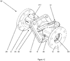
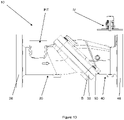
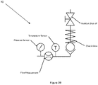
- Figures 1A thru 1D show the present invention in the form of a combination valve generally indicated as 10 having one or more embedded measurement sensors P, T, F, a check valve CV and an isolation valve IV featuring a valve body inlet 20 and a valve body outlet 40.
- the valve body inlet 20 includes a pipe portion 22 having an inlet portion 24 for receiving a fluid flow and an outlet portion 26 for providing the fluid flow from the valve body inlet 20.
- the pipe portion 22 may be configured to extend along a pipe portion axis A.
- the valve body inlet 20 includes an inlet flange portion 28 coupled to the inlet portion 24 and extending outwardly perpendicular to the pipe portion axis A for coupling to input piping (not shown) providing the fluid flow.
- the valve body inlet 20 includes an outlet flange portion 30 coupled to the outlet portion 26, and extended outwardly and obliquely with respect to the pipe portion axis A at an angle of about 45°.
- Fig. 1A see the plane defined by the arrows a-a in relation to the pipe portion axis A and the corresponding pipe portion axis A'.
- the valve body outlet 40 includes a corresponding pipe portion 42 with a corresponding inlet portion 44 for receiving the fluid flow from the valve body inlet 20 and a corresponding outlet portion 46 for providing the fluid flow from the valve body outlet 40, and being configured to extend along a corresponding pipe portion axis A'.
- the valve body outlet 40 includes a corresponding outlet flange portion 48 coupled to the corresponding outlet portion 46 for coupling to output piping (not shown) for receiving the fluid flow from the combination valve 10, and extending outwardly perpendicular to the corresponding pipe portion axis A'.
- the valve body outlet 40 includes a corresponding inlet flange portion 50 coupled to the corresponding inlet portion 44 of the valve body outlet 40, extended outwardly and obliquely with respect to the corresponding pipe portion axis A' at an angle of about 45°, and configured to couple to the outlet flange portion 30 of the valve body inlet 20 for connecting the valve body inlet 20 and valve body outlet 40 together, e.g., using bolts.
- a flange portion 50 coupled to the corresponding inlet portion 44 of the valve body outlet 40, extended outwardly and obliquely with respect to the corresponding pipe portion axis A' at an angle of about 45°, and configured to couple to the outlet flange portion 30 of the valve body inlet 20 for connecting the valve body inlet 20 and valve body outlet 40 together, e.g., using bolts.
- Fig. 1A see the plane defined by the arrows a-a in relation to the pipe portion axis A and the corresponding pipe portion axis A'.
- valve body inlet 20 and the valve body outlet 40 can be mounted (e.g., in the field by a field technician) in one of the following orientations:
- the valve body inlet 20 includes the one or more embedded measurement sensors P, T, F, including where the one or more embedded measurement sensors are configured to sense some combination of flow rate, temperature, or pressure in fluid flowing thru the combination valve 10.
- the invention is intended to include, where the valve body outlet 40 includes the one or more embedded measurement sensors P, T, F.
- the valve body outlet 40 includes the check valve CV, the isolation valve IV, or both, e.g., consistent with that shown in the drawing.
- the invention is intended to include, where the valve body inlet 20 includes the check valve CV, the isolation valve IV, or both.
- the isolation valve IV is shown in Fig. 1A as a ball valve BV, although the invention is intended to include other types or kinds of isolation valves either now known or later developed in the future.
- the flange portions 28, 30 and the corresponding flange portions 48, 50 may be configured with corresponding openings O for receiving bolts B to couple together, e.g., like the outlet flange portion 30 and the corresponding inlet flange portion 50 as shown.
- the corresponding openings O may be configured in four corners so that the corresponding inlet flange portion 50 of the valve body outlet 40 can be mounted to the outlet flange portion 28 of the valve body inlet 20 in either the straight 180°-orientation, or the angled 90°-orientation, or the intermediate angled orientation.
- the invention is intended to include, where the outlet flange portion 30 and the corresponding inlet flange portion 50 may be configured with more or less than four openings and coupled together with more or less than four bolts.
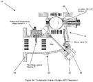
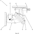
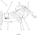
- Figures 2A thru 4C show the other configurations/orientations and include reference labels corresponding to the labelling of the parts/components in Figures 1A thru 1D .
- Figures 2A thru 2D show the combination valve 10 where the valve body inlet 20 and the valve body outlet 40 are coupled together in a perpendicular or 90°-orientation.
- Fig. 2B shows the combination valve 10 having the pressure sensor P, flow measurement device F and temperature sensor T arranged on one axis and the check valve CV and isolation shut-off valve IV arranged along a perpendicular axis.
- FIGS 3A thru 3C show the combination valve 10 where the valve body inlet 20 and the valve body outlet 40 are coupled together in an intermediately-angled orientation.
- Figures 4A thru 4C show an alternate flange design for the combination valve where the valve body inlet 20 and the valve body outlet 40 are respectively coupled together similar to the angular orientation in Figures 1 A thru 1 D , 2A thru 2D and 3A thru 3C .
- Fig. 4A shows the combination valve 10 having a straight or 180°orientation similar to that shown in Figs. 1 A thru 1 D ;
- Fig. 4B shows the combination valve 10 having a perpendicular or 90°-orientation similar to that shown in Figs. 2A thru 2D ;
- Fig. 4C shows the combination valve 10 having an intermediately-angled orientation similar to that shown in Fig. 3A thru 3C .
- this application is related to patent application serial no. 15/173,798 ( US 2017/ 023 391 A1), filed 6 June 2016 , which claims benefit to provisional application serial no. 62/171,023, filed 4 June 2015 ; patent application serial no. 15/262,430 ( US 2017/ 191 681 A1), filed 12 September 2016 , which claims benefit to provisional application serial no. 62/217,355, filed 11 September 2015 ; as well as patent application serial no. 15/715,779 ( US 2018/ 128 387 A1), filed 26 September 2017 , which claims benefit to provisional application serial no. 62/399,614, filed 26 September 2016 .
Landscapes
- Engineering & Computer Science (AREA)
- General Engineering & Computer Science (AREA)
- Mechanical Engineering (AREA)
- Chemical & Material Sciences (AREA)
- Combustion & Propulsion (AREA)
- Measuring Volume Flow (AREA)
- Valve Housings (AREA)
Applications Claiming Priority (2)
| Application Number | Priority Date | Filing Date | Title |
|---|---|---|---|
| US201662425289P | 2016-11-22 | 2016-11-22 | |
| PCT/US2017/063024 WO2018098285A1 (en) | 2016-11-22 | 2017-11-22 | Combination of isolation valve and check valve with integrated flow rate, pressure and/or temperature measurement and field configurability |
Publications (3)
| Publication Number | Publication Date |
|---|---|
| EP3545220A1 EP3545220A1 (en) | 2019-10-02 |
| EP3545220A4 EP3545220A4 (en) | 2020-07-22 |
| EP3545220B1 true EP3545220B1 (en) | 2022-07-06 |
Family
ID=62196117
Family Applications (1)
| Application Number | Title | Priority Date | Filing Date |
|---|---|---|---|
| EP17874772.1A Not-in-force EP3545220B1 (en) | 2016-11-22 | 2017-11-22 | Combination of isolation valve and check valve with integrated flow rate, pressure and/or temperature measurement and field configurability |
Country Status (7)
| Country | Link |
|---|---|
| US (1) | US10443880B2 (da) |
| EP (1) | EP3545220B1 (da) |
| CN (2) | CN110023662A (da) |
| AU (1) | AU2017363262B2 (da) |
| DK (1) | DK3545220T3 (da) |
| RU (1) | RU2716777C1 (da) |
| WO (1) | WO2018098285A1 (da) |
Families Citing this family (14)
| Publication number | Priority date | Publication date | Assignee | Title |
|---|---|---|---|---|
| US10914412B2 (en) | 2018-06-28 | 2021-02-09 | Watts Regulator Co. | Backflow prevention assembly having a variable lay-length and orientation |
| DE102018113952B4 (de) * | 2018-07-30 | 2022-01-27 | Danfoss Power Solutions Aps | Hydraulische Lenkeinheit |
| US11320059B2 (en) * | 2018-09-11 | 2022-05-03 | Varisco S.r.l. | Check valve |
| DE102019111977B4 (de) * | 2019-05-08 | 2026-02-05 | Pittway Sàrl | Anordnung zur Messung einer Leckage in einem Trinkwasserversorgungssystem und Druckminderer |
| US11795666B2 (en) | 2019-05-08 | 2023-10-24 | Watts Regulator Co. | Wireless communication system within a mechanical room |
| US11815424B2 (en) * | 2019-05-08 | 2023-11-14 | Watts Regulator Co. | Backflow prevention system test cock with a fluid sensor |
| DE102019119302A1 (de) * | 2019-07-16 | 2021-01-21 | Norma Germany Gmbh | Ablaufstutzen zum getrennten Auslassen von Flüssigkeiten unterschiedlicher Dichte |
| CN110500443B (zh) * | 2019-08-26 | 2020-11-06 | 赵国栋 | 可对阀前及阀后的流体速度进行监测的比例式减压阀 |
| EP3835494A1 (en) | 2019-12-10 | 2021-06-16 | Watts Regulator Co. | System for monitoring backflow preventer condition |
| US12195954B2 (en) | 2019-12-10 | 2025-01-14 | Watts Regulator Co. | System for monitoring backflow preventer condition |
| US11719352B2 (en) | 2020-08-17 | 2023-08-08 | Watts Regulator Co. | Check cover assemblies for backflow prevention assemblies with integrated test cock protection shroud |
| US11773992B2 (en) | 2020-08-17 | 2023-10-03 | Watts Regulator Co. | Backflow prevention assembly with a linkage |
| US11739507B2 (en) | 2020-12-09 | 2023-08-29 | Watts Regulator Co. | Test cock with integrated extraction tool |
| USD1021000S1 (en) | 2021-08-17 | 2024-04-02 | Watts Regulator Co. | Valve assembly and body for same |
Family Cites Families (36)
| Publication number | Priority date | Publication date | Assignee | Title |
|---|---|---|---|---|
| GB138496A (en) * | 1919-04-14 | 1920-02-12 | Cammell Laird And Company Ltd | Improvements relating to storm valves for ships' scupper and soilpipe outlets, and the like |
| US1367911A (en) | 1920-06-01 | 1921-02-08 | Charles C Koplin | Stopcock and check-valve |
| US2715414A (en) | 1951-11-20 | 1955-08-16 | Robert B Kinzbach | Combined automatic shut-off and check valve assembly for tanks and the like |
| DE956006C (de) * | 1955-04-26 | 1957-01-10 | Jenaer Glaswerk Schott & Gen | Vorrichtung zur selbsttaetigen Einspeisung eines Mediums in das Rohrsystem eines zweiten Mediums |
| AT204340B (de) * | 1955-08-22 | 1959-07-10 | Durabla Mfg Company | Rückschlagventil-Aggregat für Rohrleitungen u. dgl. |
| US3218024A (en) * | 1962-07-18 | 1965-11-16 | Sealol | Fluid motor actuated ball valve |
| US3420493A (en) | 1965-12-13 | 1969-01-07 | Wilbur P Kraft | Combination metering,check and shut-off valve |
| US4402340A (en) | 1981-05-01 | 1983-09-06 | Lockwood Jr Hanford N | Pressure-responsive shut-off valve |
| DE3414077A1 (de) * | 1984-04-13 | 1985-10-24 | Passavant-Werke AG & Co KG, 6209 Aarbergen | Winkelveraenderbares kniestueck |
| US5406979A (en) | 1986-06-16 | 1995-04-18 | Acf Manufacturing, Inc. | Valve and sensor arrangement |
| SU1441357A1 (ru) * | 1987-06-18 | 1988-11-30 | Пензенский Политехнический Институт | Комбинированный клапан |
| JPH04501162A (ja) | 1988-10-11 | 1992-02-27 | ブラーテン,トール,フロリッヒ | コンプレッサー型の熱水加熱器のための組合わされた遮断弁と逆止め弁とを有する据付品装置 |
| AU677159B2 (en) * | 1990-08-28 | 1997-04-17 | Tour & Andersson Ab | Combined control and regulating valve for liquids or gases |
| US5261449A (en) * | 1992-05-15 | 1993-11-16 | Val-Matic Valve And Manufacturing Corp. | Quick change coupling for tilted disc check valve with top mounted dashpot |
| CN2204901Y (zh) * | 1994-10-25 | 1995-08-09 | 武汉市亚美蝶阀厂 | 挠性缓闭止回阀 |
| US5568825A (en) | 1995-12-11 | 1996-10-29 | Faulk; John W. | Automatic leak detection and shut-off system |
| US6065355A (en) | 1997-09-23 | 2000-05-23 | Halliburton Energy Services, Inc. | Non-flashing downhole fluid sampler and method |
| GB9725990D0 (en) | 1997-12-09 | 1998-02-04 | Alco Hi Tek Ltd | Valve |
| US6357467B1 (en) | 2000-03-27 | 2002-03-19 | Grinnell Corporation | Automatic water supply shutoff valve |
| AU6662501A (en) | 2000-05-30 | 2001-12-11 | Igc Polycold Systems, Inc. | A low temperature refrigeration system |
| US7478540B2 (en) | 2001-10-26 | 2009-01-20 | Brooks Automation, Inc. | Methods of freezeout prevention and temperature control for very low temperature mixed refrigerant systems |
| US7174915B2 (en) * | 2003-11-24 | 2007-02-13 | Dale Fazekas | Water re-circulation valve |
| US7445025B2 (en) | 2006-03-13 | 2008-11-04 | Itt Manufacturing Enterprises, Inc | Combination valve |
| US8596296B2 (en) * | 2008-04-30 | 2013-12-03 | Broen A/S | Regulation valve |
| RU2366846C1 (ru) * | 2008-06-18 | 2009-09-10 | Селиванов Николай Павлович | Регулирующий клапан |
| WO2010109623A1 (ja) | 2009-03-26 | 2010-09-30 | 株式会社栗本鐵工所 | 粉体用バルブ |
| NO334053B1 (no) | 2011-03-24 | 2013-11-25 | Braathen Thor F | Forbedret kombinasjonsventil |
| US20130048114A1 (en) | 2011-08-26 | 2013-02-28 | Optimum Energy, Llc | Controlled hydronic distribution system |
| CN105492813B (zh) * | 2013-06-11 | 2018-01-30 | 流体处理有限责任公司 | 具有集成内部流量、压力和/或温度测量的组合隔离阀和止回阀 |
| CN103334920B (zh) * | 2013-07-12 | 2015-12-09 | 株洲南方阀门股份有限公司 | 一种斜板止回阀 |
| US9791054B2 (en) | 2014-11-18 | 2017-10-17 | Saudi Arabian Oil Company | Isolatable non-slam piston check valve |
| EP3073205B1 (en) | 2015-03-27 | 2020-07-22 | Honeywell Technologies Sarl | Method for operating a hydronic heating and/or cooling system, control valve and hydronic heating and/or cooling system |
| EP3304008B1 (en) | 2015-06-04 | 2020-03-04 | Fluid Handling LLC. | Contoured insert for flow verification |
| US10302233B2 (en) | 2015-06-12 | 2019-05-28 | Nibco Inc. | Temperature and pressure gauge adaptors |
| WO2017044927A1 (en) | 2015-09-11 | 2017-03-16 | Fluid Handling Llc | Combination isolation valve and check valve with integral flow rate, pressure, and/or temperature measurement with wireless power |
| DK3516278T3 (da) | 2016-09-26 | 2022-01-31 | Fluid Handling Llc | Kontureret kontraventilskive til lavt revnedannelsestryk |
-
2017
- 2017-11-22 AU AU2017363262A patent/AU2017363262B2/en not_active Ceased
- 2017-11-22 CN CN201780071904.5A patent/CN110023662A/zh active Pending
- 2017-11-22 WO PCT/US2017/063024 patent/WO2018098285A1/en not_active Ceased
- 2017-11-22 EP EP17874772.1A patent/EP3545220B1/en not_active Not-in-force
- 2017-11-22 DK DK17874772.1T patent/DK3545220T3/da active
- 2017-11-22 CN CN202310957289.5A patent/CN116951139A/zh active Pending
- 2017-11-22 US US15/821,084 patent/US10443880B2/en active Active
- 2017-11-22 RU RU2019115445A patent/RU2716777C1/ru active
Also Published As
| Publication number | Publication date |
|---|---|
| WO2018098285A1 (en) | 2018-05-31 |
| US10443880B2 (en) | 2019-10-15 |
| AU2017363262A1 (en) | 2019-06-06 |
| DK3545220T3 (da) | 2022-08-01 |
| US20180156488A1 (en) | 2018-06-07 |
| CN110023662A (zh) | 2019-07-16 |
| RU2716777C1 (ru) | 2020-03-16 |
| CN116951139A (zh) | 2023-10-27 |
| EP3545220A4 (en) | 2020-07-22 |
| AU2017363262B2 (en) | 2021-02-11 |
| EP3545220A1 (en) | 2019-10-02 |
Similar Documents
| Publication | Publication Date | Title |
|---|---|---|
| EP3545220B1 (en) | Combination of isolation valve and check valve with integrated flow rate, pressure and/or temperature measurement and field configurability | |
| US9170137B2 (en) | Rotatable orifice plate for direct flow measurement | |
| EP3132233B1 (en) | Flow meter | |
| EP2948742B1 (en) | Rotatable orifice plate for direct flow measurement | |
| JP6503462B2 (ja) | ロッド式圧力伝達継手及び継手装置 | |
| US20180106648A1 (en) | Subsea flow meter assembly | |
| US8701497B2 (en) | Fluid flow testing system | |
| JP2004003647A (ja) | ボールに直接組み込まれてなる流量ゲージを有するボールバルブ | |
| US20140238495A1 (en) | Dynamic Fluid Gas Bleeder Manifold | |
| KR101767415B1 (ko) | 이상 유체 센서 | |
| EP3304008B1 (en) | Contoured insert for flow verification | |
| US10222252B2 (en) | Portable verification system and method for use in verifying a gas pipeline flow meter when in field | |
| CN103076052A (zh) | 一种探测器安装管组 | |
| US11860010B2 (en) | Differential pressure metering apparatus for a flow restrictor pipe section | |
| Duda | Selecting and Specifying Pipe Flow Meters. | |
| US20080060449A1 (en) | Pressure drop flow meter having interchangeable, metal-to-metal sealing metering element | |
| CN219530569U (zh) | 带反吹的气体分配器及吹气式液位计 | |
| US20240068853A1 (en) | Device for flow and volume measurement and consumption detection in hydrants, hose connections or any type of outlet | |
| WO2010109182A1 (en) | Compact provers | |
| JP2003227740A (ja) | 流量計測装置およびガスメータ | |
| CN102033140A (zh) | 一种弯头式靠背管 | |
| KR20030086438A (ko) | 유량게이지가 직접 결합되는 볼밸브 |
Legal Events
| Date | Code | Title | Description |
|---|---|---|---|
| STAA | Information on the status of an ep patent application or granted ep patent |
Free format text: STATUS: THE INTERNATIONAL PUBLICATION HAS BEEN MADE |
|
| PUAI | Public reference made under article 153(3) epc to a published international application that has entered the european phase |
Free format text: ORIGINAL CODE: 0009012 |
|
| STAA | Information on the status of an ep patent application or granted ep patent |
Free format text: STATUS: REQUEST FOR EXAMINATION WAS MADE |
|
| 17P | Request for examination filed |
Effective date: 20190624 |
|
| AK | Designated contracting states |
Kind code of ref document: A1 Designated state(s): AL AT BE BG CH CY CZ DE DK EE ES FI FR GB GR HR HU IE IS IT LI LT LU LV MC MK MT NL NO PL PT RO RS SE SI SK SM TR |
|
| AX | Request for extension of the european patent |
Extension state: BA ME |
|
| DAV | Request for validation of the european patent (deleted) | ||
| DAX | Request for extension of the european patent (deleted) | ||
| A4 | Supplementary search report drawn up and despatched |
Effective date: 20200623 |
|
| RIC1 | Information provided on ipc code assigned before grant |
Ipc: F16K 1/30 20060101AFI20200617BHEP Ipc: F16K 5/06 20060101ALI20200617BHEP Ipc: F16K 27/02 20060101ALI20200617BHEP Ipc: F16K 27/06 20060101ALI20200617BHEP Ipc: F16K 17/00 20060101ALI20200617BHEP Ipc: F16K 24/02 20060101ALI20200617BHEP Ipc: F16K 15/18 20060101ALI20200617BHEP |
|
| STAA | Information on the status of an ep patent application or granted ep patent |
Free format text: STATUS: EXAMINATION IS IN PROGRESS |
|
| 17Q | First examination report despatched |
Effective date: 20210614 |
|
| GRAP | Despatch of communication of intention to grant a patent |
Free format text: ORIGINAL CODE: EPIDOSNIGR1 |
|
| STAA | Information on the status of an ep patent application or granted ep patent |
Free format text: STATUS: GRANT OF PATENT IS INTENDED |
|
| INTG | Intention to grant announced |
Effective date: 20211110 |
|
| GRAJ | Information related to disapproval of communication of intention to grant by the applicant or resumption of examination proceedings by the epo deleted |
Free format text: ORIGINAL CODE: EPIDOSDIGR1 |
|
| STAA | Information on the status of an ep patent application or granted ep patent |
Free format text: STATUS: EXAMINATION IS IN PROGRESS |
|
| GRAS | Grant fee paid |
Free format text: ORIGINAL CODE: EPIDOSNIGR3 |
|
| STAA | Information on the status of an ep patent application or granted ep patent |
Free format text: STATUS: GRANT OF PATENT IS INTENDED |
|
| GRAP | Despatch of communication of intention to grant a patent |
Free format text: ORIGINAL CODE: EPIDOSNIGR1 |
|
| INTC | Intention to grant announced (deleted) | ||
| INTG | Intention to grant announced |
Effective date: 20220223 |
|
| GRAA | (expected) grant |
Free format text: ORIGINAL CODE: 0009210 |
|
| STAA | Information on the status of an ep patent application or granted ep patent |
Free format text: STATUS: THE PATENT HAS BEEN GRANTED |
|
| AK | Designated contracting states |
Kind code of ref document: B1 Designated state(s): AL AT BE BG CH CY CZ DE DK EE ES FI FR GB GR HR HU IE IS IT LI LT LU LV MC MK MT NL NO PL PT RO RS SE SI SK SM TR |
|
| REG | Reference to a national code |
Ref country code: AT Ref legal event code: REF Ref document number: 1503087 Country of ref document: AT Kind code of ref document: T Effective date: 20220715 Ref country code: CH Ref legal event code: EP |
|
| REG | Reference to a national code |
Ref country code: DE Ref legal event code: R096 Ref document number: 602017059347 Country of ref document: DE |
|
| REG | Reference to a national code |
Ref country code: DK Ref legal event code: T3 Effective date: 20220726 |
|
| REG | Reference to a national code |
Ref country code: IE Ref legal event code: FG4D |
|
| REG | Reference to a national code |
Ref country code: LT Ref legal event code: MG9D |
|
| REG | Reference to a national code |
Ref country code: NL Ref legal event code: MP Effective date: 20220706 |
|
| PG25 | Lapsed in a contracting state [announced via postgrant information from national office to epo] |
Ref country code: SE Free format text: LAPSE BECAUSE OF FAILURE TO SUBMIT A TRANSLATION OF THE DESCRIPTION OR TO PAY THE FEE WITHIN THE PRESCRIBED TIME-LIMIT Effective date: 20220706 Ref country code: RS Free format text: LAPSE BECAUSE OF FAILURE TO SUBMIT A TRANSLATION OF THE DESCRIPTION OR TO PAY THE FEE WITHIN THE PRESCRIBED TIME-LIMIT Effective date: 20220706 Ref country code: PT Free format text: LAPSE BECAUSE OF FAILURE TO SUBMIT A TRANSLATION OF THE DESCRIPTION OR TO PAY THE FEE WITHIN THE PRESCRIBED TIME-LIMIT Effective date: 20221107 Ref country code: NO Free format text: LAPSE BECAUSE OF FAILURE TO SUBMIT A TRANSLATION OF THE DESCRIPTION OR TO PAY THE FEE WITHIN THE PRESCRIBED TIME-LIMIT Effective date: 20221006 Ref country code: NL Free format text: LAPSE BECAUSE OF FAILURE TO SUBMIT A TRANSLATION OF THE DESCRIPTION OR TO PAY THE FEE WITHIN THE PRESCRIBED TIME-LIMIT Effective date: 20220706 Ref country code: LV Free format text: LAPSE BECAUSE OF FAILURE TO SUBMIT A TRANSLATION OF THE DESCRIPTION OR TO PAY THE FEE WITHIN THE PRESCRIBED TIME-LIMIT Effective date: 20220706 Ref country code: LT Free format text: LAPSE BECAUSE OF FAILURE TO SUBMIT A TRANSLATION OF THE DESCRIPTION OR TO PAY THE FEE WITHIN THE PRESCRIBED TIME-LIMIT Effective date: 20220706 Ref country code: FI Free format text: LAPSE BECAUSE OF FAILURE TO SUBMIT A TRANSLATION OF THE DESCRIPTION OR TO PAY THE FEE WITHIN THE PRESCRIBED TIME-LIMIT Effective date: 20220706 Ref country code: ES Free format text: LAPSE BECAUSE OF FAILURE TO SUBMIT A TRANSLATION OF THE DESCRIPTION OR TO PAY THE FEE WITHIN THE PRESCRIBED TIME-LIMIT Effective date: 20220706 |
|
| REG | Reference to a national code |
Ref country code: AT Ref legal event code: MK05 Ref document number: 1503087 Country of ref document: AT Kind code of ref document: T Effective date: 20220706 |
|
| PG25 | Lapsed in a contracting state [announced via postgrant information from national office to epo] |
Ref country code: PL Free format text: LAPSE BECAUSE OF FAILURE TO SUBMIT A TRANSLATION OF THE DESCRIPTION OR TO PAY THE FEE WITHIN THE PRESCRIBED TIME-LIMIT Effective date: 20220706 Ref country code: IS Free format text: LAPSE BECAUSE OF FAILURE TO SUBMIT A TRANSLATION OF THE DESCRIPTION OR TO PAY THE FEE WITHIN THE PRESCRIBED TIME-LIMIT Effective date: 20221106 Ref country code: HR Free format text: LAPSE BECAUSE OF FAILURE TO SUBMIT A TRANSLATION OF THE DESCRIPTION OR TO PAY THE FEE WITHIN THE PRESCRIBED TIME-LIMIT Effective date: 20220706 Ref country code: GR Free format text: LAPSE BECAUSE OF FAILURE TO SUBMIT A TRANSLATION OF THE DESCRIPTION OR TO PAY THE FEE WITHIN THE PRESCRIBED TIME-LIMIT Effective date: 20221007 |
|
| REG | Reference to a national code |
Ref country code: DE Ref legal event code: R082 Ref document number: 602017059347 Country of ref document: DE Representative=s name: WOERZ PATENTANWAELTE PARTNERSCHAFTSGESELLSCHAF, DE |
|
| REG | Reference to a national code |
Ref country code: DE Ref legal event code: R097 Ref document number: 602017059347 Country of ref document: DE |
|
| PG25 | Lapsed in a contracting state [announced via postgrant information from national office to epo] |
Ref country code: SM Free format text: LAPSE BECAUSE OF FAILURE TO SUBMIT A TRANSLATION OF THE DESCRIPTION OR TO PAY THE FEE WITHIN THE PRESCRIBED TIME-LIMIT Effective date: 20220706 Ref country code: RO Free format text: LAPSE BECAUSE OF FAILURE TO SUBMIT A TRANSLATION OF THE DESCRIPTION OR TO PAY THE FEE WITHIN THE PRESCRIBED TIME-LIMIT Effective date: 20220706 Ref country code: CZ Free format text: LAPSE BECAUSE OF FAILURE TO SUBMIT A TRANSLATION OF THE DESCRIPTION OR TO PAY THE FEE WITHIN THE PRESCRIBED TIME-LIMIT Effective date: 20220706 Ref country code: AT Free format text: LAPSE BECAUSE OF FAILURE TO SUBMIT A TRANSLATION OF THE DESCRIPTION OR TO PAY THE FEE WITHIN THE PRESCRIBED TIME-LIMIT Effective date: 20220706 |
|
| PLBE | No opposition filed within time limit |
Free format text: ORIGINAL CODE: 0009261 |
|
| STAA | Information on the status of an ep patent application or granted ep patent |
Free format text: STATUS: NO OPPOSITION FILED WITHIN TIME LIMIT |
|
| PG25 | Lapsed in a contracting state [announced via postgrant information from national office to epo] |
Ref country code: SK Free format text: LAPSE BECAUSE OF FAILURE TO SUBMIT A TRANSLATION OF THE DESCRIPTION OR TO PAY THE FEE WITHIN THE PRESCRIBED TIME-LIMIT Effective date: 20220706 Ref country code: EE Free format text: LAPSE BECAUSE OF FAILURE TO SUBMIT A TRANSLATION OF THE DESCRIPTION OR TO PAY THE FEE WITHIN THE PRESCRIBED TIME-LIMIT Effective date: 20220706 |
|
| 26N | No opposition filed |
Effective date: 20230411 |
|
| PG25 | Lapsed in a contracting state [announced via postgrant information from national office to epo] |
Ref country code: MC Free format text: LAPSE BECAUSE OF FAILURE TO SUBMIT A TRANSLATION OF THE DESCRIPTION OR TO PAY THE FEE WITHIN THE PRESCRIBED TIME-LIMIT Effective date: 20220706 Ref country code: AL Free format text: LAPSE BECAUSE OF FAILURE TO SUBMIT A TRANSLATION OF THE DESCRIPTION OR TO PAY THE FEE WITHIN THE PRESCRIBED TIME-LIMIT Effective date: 20220706 |
|
| REG | Reference to a national code |
Ref country code: CH Ref legal event code: PL |
|
| REG | Reference to a national code |
Ref country code: BE Ref legal event code: MM Effective date: 20221130 |
|
| PG25 | Lapsed in a contracting state [announced via postgrant information from national office to epo] |
Ref country code: LI Free format text: LAPSE BECAUSE OF NON-PAYMENT OF DUE FEES Effective date: 20221130 Ref country code: CH Free format text: LAPSE BECAUSE OF NON-PAYMENT OF DUE FEES Effective date: 20221130 |
|
| PG25 | Lapsed in a contracting state [announced via postgrant information from national office to epo] |
Ref country code: SI Free format text: LAPSE BECAUSE OF FAILURE TO SUBMIT A TRANSLATION OF THE DESCRIPTION OR TO PAY THE FEE WITHIN THE PRESCRIBED TIME-LIMIT Effective date: 20220706 Ref country code: LU Free format text: LAPSE BECAUSE OF NON-PAYMENT OF DUE FEES Effective date: 20221122 |
|
| PG25 | Lapsed in a contracting state [announced via postgrant information from national office to epo] |
Ref country code: IE Free format text: LAPSE BECAUSE OF NON-PAYMENT OF DUE FEES Effective date: 20221122 |
|
| PG25 | Lapsed in a contracting state [announced via postgrant information from national office to epo] |
Ref country code: FR Free format text: LAPSE BECAUSE OF NON-PAYMENT OF DUE FEES Effective date: 20221130 Ref country code: BE Free format text: LAPSE BECAUSE OF NON-PAYMENT OF DUE FEES Effective date: 20221130 |
|
| PGFP | Annual fee paid to national office [announced via postgrant information from national office to epo] |
Ref country code: GB Payment date: 20231127 Year of fee payment: 7 |
|
| PG25 | Lapsed in a contracting state [announced via postgrant information from national office to epo] |
Ref country code: IT Free format text: LAPSE BECAUSE OF FAILURE TO SUBMIT A TRANSLATION OF THE DESCRIPTION OR TO PAY THE FEE WITHIN THE PRESCRIBED TIME-LIMIT Effective date: 20220706 |
|
| PGFP | Annual fee paid to national office [announced via postgrant information from national office to epo] |
Ref country code: DK Payment date: 20231127 Year of fee payment: 7 Ref country code: DE Payment date: 20231129 Year of fee payment: 7 |
|
| PG25 | Lapsed in a contracting state [announced via postgrant information from national office to epo] |
Ref country code: HU Free format text: LAPSE BECAUSE OF FAILURE TO SUBMIT A TRANSLATION OF THE DESCRIPTION OR TO PAY THE FEE WITHIN THE PRESCRIBED TIME-LIMIT; INVALID AB INITIO Effective date: 20171122 |
|
| PG25 | Lapsed in a contracting state [announced via postgrant information from national office to epo] |
Ref country code: CY Free format text: LAPSE BECAUSE OF FAILURE TO SUBMIT A TRANSLATION OF THE DESCRIPTION OR TO PAY THE FEE WITHIN THE PRESCRIBED TIME-LIMIT Effective date: 20220706 |
|
| PG25 | Lapsed in a contracting state [announced via postgrant information from national office to epo] |
Ref country code: MK Free format text: LAPSE BECAUSE OF FAILURE TO SUBMIT A TRANSLATION OF THE DESCRIPTION OR TO PAY THE FEE WITHIN THE PRESCRIBED TIME-LIMIT Effective date: 20220706 |
|
| PG25 | Lapsed in a contracting state [announced via postgrant information from national office to epo] |
Ref country code: BG Free format text: LAPSE BECAUSE OF FAILURE TO SUBMIT A TRANSLATION OF THE DESCRIPTION OR TO PAY THE FEE WITHIN THE PRESCRIBED TIME-LIMIT Effective date: 20220706 |
|
| PG25 | Lapsed in a contracting state [announced via postgrant information from national office to epo] |
Ref country code: MT Free format text: LAPSE BECAUSE OF FAILURE TO SUBMIT A TRANSLATION OF THE DESCRIPTION OR TO PAY THE FEE WITHIN THE PRESCRIBED TIME-LIMIT Effective date: 20220706 |
|
| REG | Reference to a national code |
Ref country code: DE Ref legal event code: R119 Ref document number: 602017059347 Country of ref document: DE |
|
| REG | Reference to a national code |
Ref country code: DK Ref legal event code: EBP Effective date: 20241130 |
|
| GBPC | Gb: european patent ceased through non-payment of renewal fee |
Effective date: 20241122 |
|
| PG25 | Lapsed in a contracting state [announced via postgrant information from national office to epo] |
Ref country code: DE Free format text: LAPSE BECAUSE OF NON-PAYMENT OF DUE FEES Effective date: 20250603 Ref country code: DK Free format text: LAPSE BECAUSE OF NON-PAYMENT OF DUE FEES Effective date: 20241130 |
|
| PG25 | Lapsed in a contracting state [announced via postgrant information from national office to epo] |
Ref country code: GB Free format text: LAPSE BECAUSE OF NON-PAYMENT OF DUE FEES Effective date: 20241122 |
|
| PG25 | Lapsed in a contracting state [announced via postgrant information from national office to epo] |
Ref country code: TR Free format text: LAPSE BECAUSE OF FAILURE TO SUBMIT A TRANSLATION OF THE DESCRIPTION OR TO PAY THE FEE WITHIN THE PRESCRIBED TIME-LIMIT Effective date: 20220706 |