EP3545378B1 - Anordnung zur differenzierten steuerung von fahrzeugen auf einer baustelle - Google Patents
Anordnung zur differenzierten steuerung von fahrzeugen auf einer baustelle Download PDFInfo
- Publication number
- EP3545378B1 EP3545378B1 EP16922054.8A EP16922054A EP3545378B1 EP 3545378 B1 EP3545378 B1 EP 3545378B1 EP 16922054 A EP16922054 A EP 16922054A EP 3545378 B1 EP3545378 B1 EP 3545378B1
- Authority
- EP
- European Patent Office
- Prior art keywords
- work site
- radio
- signals
- zone
- vehicle
- Prior art date
- Legal status (The legal status is an assumption and is not a legal conclusion. Google has not performed a legal analysis and makes no representation as to the accuracy of the status listed.)
- Active
Links
Images



Classifications
-
- G—PHYSICS
- G05—CONTROLLING; REGULATING
- G05D—SYSTEMS FOR CONTROLLING OR REGULATING NON-ELECTRIC VARIABLES
- G05D1/00—Control of position, course, altitude or attitude of land, water, air or space vehicles, e.g. using automatic pilots
- G05D1/02—Control of position or course in two dimensions
- G05D1/021—Control of position or course in two dimensions specially adapted to land vehicles
- G05D1/0276—Control of position or course in two dimensions specially adapted to land vehicles using signals provided by a source external to the vehicle
- G05D1/028—Control of position or course in two dimensions specially adapted to land vehicles using signals provided by a source external to the vehicle using a RF signal
-
- B—PERFORMING OPERATIONS; TRANSPORTING
- B60—VEHICLES IN GENERAL
- B60W—CONJOINT CONTROL OF VEHICLE SUB-UNITS OF DIFFERENT TYPE OR DIFFERENT FUNCTION; CONTROL SYSTEMS SPECIALLY ADAPTED FOR HYBRID VEHICLES; ROAD VEHICLE DRIVE CONTROL SYSTEMS FOR PURPOSES NOT RELATED TO THE CONTROL OF A PARTICULAR SUB-UNIT
- B60W60/00—Drive control systems specially adapted for autonomous road vehicles
- B60W60/001—Planning or execution of driving tasks
- B60W60/0025—Planning or execution of driving tasks specially adapted for specific operations
-
- B—PERFORMING OPERATIONS; TRANSPORTING
- B60—VEHICLES IN GENERAL
- B60W—CONJOINT CONTROL OF VEHICLE SUB-UNITS OF DIFFERENT TYPE OR DIFFERENT FUNCTION; CONTROL SYSTEMS SPECIALLY ADAPTED FOR HYBRID VEHICLES; ROAD VEHICLE DRIVE CONTROL SYSTEMS FOR PURPOSES NOT RELATED TO THE CONTROL OF A PARTICULAR SUB-UNIT
- B60W30/00—Purposes of road vehicle drive control systems not related to the control of a particular sub-unit, e.g. of systems using conjoint control of vehicle sub-units
- B60W30/14—Adaptive cruise control
- B60W30/143—Speed control
- B60W30/146—Speed limiting
-
- B—PERFORMING OPERATIONS; TRANSPORTING
- B60—VEHICLES IN GENERAL
- B60W—CONJOINT CONTROL OF VEHICLE SUB-UNITS OF DIFFERENT TYPE OR DIFFERENT FUNCTION; CONTROL SYSTEMS SPECIALLY ADAPTED FOR HYBRID VEHICLES; ROAD VEHICLE DRIVE CONTROL SYSTEMS FOR PURPOSES NOT RELATED TO THE CONTROL OF A PARTICULAR SUB-UNIT
- B60W60/00—Drive control systems specially adapted for autonomous road vehicles
- B60W60/001—Planning or execution of driving tasks
-
- G—PHYSICS
- G05—CONTROLLING; REGULATING
- G05D—SYSTEMS FOR CONTROLLING OR REGULATING NON-ELECTRIC VARIABLES
- G05D1/00—Control of position, course, altitude or attitude of land, water, air or space vehicles, e.g. using automatic pilots
- G05D1/02—Control of position or course in two dimensions
- G05D1/021—Control of position or course in two dimensions specially adapted to land vehicles
- G05D1/0287—Control of position or course in two dimensions specially adapted to land vehicles involving a plurality of land vehicles, e.g. fleet or convoy travelling
- G05D1/0291—Fleet control
-
- B—PERFORMING OPERATIONS; TRANSPORTING
- B60—VEHICLES IN GENERAL
- B60W—CONJOINT CONTROL OF VEHICLE SUB-UNITS OF DIFFERENT TYPE OR DIFFERENT FUNCTION; CONTROL SYSTEMS SPECIALLY ADAPTED FOR HYBRID VEHICLES; ROAD VEHICLE DRIVE CONTROL SYSTEMS FOR PURPOSES NOT RELATED TO THE CONTROL OF A PARTICULAR SUB-UNIT
- B60W2300/00—Indexing codes relating to the type of vehicle
- B60W2300/17—Construction vehicles, e.g. graders, excavators
-
- B—PERFORMING OPERATIONS; TRANSPORTING
- B60—VEHICLES IN GENERAL
- B60W—CONJOINT CONTROL OF VEHICLE SUB-UNITS OF DIFFERENT TYPE OR DIFFERENT FUNCTION; CONTROL SYSTEMS SPECIALLY ADAPTED FOR HYBRID VEHICLES; ROAD VEHICLE DRIVE CONTROL SYSTEMS FOR PURPOSES NOT RELATED TO THE CONTROL OF A PARTICULAR SUB-UNIT
- B60W2556/00—Input parameters relating to data
- B60W2556/45—External transmission of data to or from the vehicle
-
- B—PERFORMING OPERATIONS; TRANSPORTING
- B60—VEHICLES IN GENERAL
- B60W—CONJOINT CONTROL OF VEHICLE SUB-UNITS OF DIFFERENT TYPE OR DIFFERENT FUNCTION; CONTROL SYSTEMS SPECIALLY ADAPTED FOR HYBRID VEHICLES; ROAD VEHICLE DRIVE CONTROL SYSTEMS FOR PURPOSES NOT RELATED TO THE CONTROL OF A PARTICULAR SUB-UNIT
- B60W2720/00—Output or target parameters relating to overall vehicle dynamics
- B60W2720/10—Longitudinal speed
Definitions
- the invention relates to an arrangement for a work site according claim 1 and a method for creating a work site zone on a work site according to claim 6.
- the invention is applicable on work sites, such as quarries, and vehicles on a work site, and particularly on work sites where autonomous machines, manually operated working machines and walking people are mixed.
- the autonomous machines can be haulers for transportation of boulders, gravel, sand, etc.
- the application of the invention is not restricted to this particular machine, but may also be used in other vehicles, such as any kind of dump trucks or loaders or other construction equipment.
- US2016/271800 relates to a warehouse robot and its interaction with warehouse workers.
- Short range transmissions are used to identify potential interactions between warehouse workers and warehouse robots in automated warehouses.
- the robot can detect a warehouse worker that is within range when the RFID tags on the robot are written to by the RFID reader, and when the worker is within a predetermined distance from the robot, the speed of the robot is reduced to minimize the risk of accidents.
- US2005/188493 relates to a self-propelling cleaner.
- the self-propelling cleaner operates a main body in a silent mode and sets the propelling speed of the main body to a low speed lower than a normal speed irrespective whether the selected operation mode is a normal mode or the silent mode, so that noise generated from the main body can be reduced.
- noise generated from the main body can be reduced when the self-propelling cleaner approaches the user, so that the user's action taken at this time cannot be interfered by noise generated from the self-propelling cleaner.
- EP 2 476 034 relates to a method and a system for remote control of vehicles, in which a video that is recorded by at least one video camera is transmitted in real time from a remote-controlled vehicle, via at least one mobile radio link over a mobile radio network, to a control centre.
- An object of the invention is to provide an arrangement defined by way of introduction, which arrangement enables a differentiated control of vehicles on a work site. Such differentiated control can then be utilized for increasing safety at a work site while maintaining a high productivity, particularly when the vehicle fleet of the work site comprises autonomous vehicles.
- an arrangement according to claim 1 is provided.
- the above-mentioned object is achieved by such an arrangement.
- the radio transmitter is arranged to define a work site zone of the work site by means of the coverage of the radio signals from the radio transmitter, wherein a predetermined vehicle operation condition for the vehicle is different in the work site zone when receiving the radio signals compared to outside the work site zone when not receiving the radio signals
- the vehicles can be driven or operated in one way within the work site zone, where only autonomous vehicles are permitted for instance, and in another way outside the work site zone, where autonomous vehicles and operator-controlled vehicles are mixed for instance.
- This arrangement gives advantages, since often the work site conditions require that a vehicle is controlled in one way in one area and in another way in another area of the work site. This will give a non-complicated and relatively inexpensive arrangement that is not dependent of any GPS or similar system for differentiating the conditions for the vehicles of the vehicle fleet on a work site.
- the predetermined vehicle operation condition is the allowed vehicle speed
- the allowed vehicle speed in the work site zone defined by the radio transmitter is preferably higher than the allowed vehicle speed in the work site area outside the work site zone not covered by the radio signals.
- the radio transmitter has a relatively short range not exceeding 500 meters, preferably not exceeding 200 meters and often not exceeding 100 meters.
- a suitable effective coverage or range can be selected in the interval 30-100 meters, preferably 50-100 meters.
- a size of the work site zone relevant to a work site can be selected.
- the work site can be divided into different zones with high resolution and a plurality of the transmitters can be used for achieving the desired shape of the work site zone. In addition, this also makes the radio transmitter and receiver inexpensive.
- the arrangement comprises a pole to which the radio transmitter is attached, wherein the pole is movable and arrangeable in different positions at the work site.
- the position of the radio transmitter as well as the position of the work site zone can be varied, and the work site zones of the work site can be adjusted or changed in case the conditions on the work site would change.
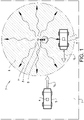
- Fig. 1 is a schematic illustration of a work site 1 provided with an arrangement 2 according to one embodiment the invention.
- the arrangement 2 comprises a radio transmitter 3 arranged at the work site 1 for transmitting signals 7 receivable by a radio receiver 4 arranged on a vehicle 5 at the work site 1.
- a radio receiver 4 arranged on a vehicle 5 at the work site 1.
- the radio receiver 4 is able to receive the radio signals 7 and generate electrical signals based on the radio signals provided that the receiver 4 is within the coverage of the radio transmitter 3.
- the radio transmitter 3 is arranged to define a work site zone 6 of the work site 1 by means of the coverage of the radio signals 7 from the radio transmitter 3.
- a threshold value for the signal power is used and/or by using of a certain frequency band and/or by choosing the time during which the received signal is integrated.
- the radio signals will however comprise and transfer some kind of message, code or number to be used by the radio receiver for verifying the identity of the radio transmitter, to eliminate or at least reduce the risk of receiving signals from an unauthorized source.
- the frequency can be for example around 5 GHz or 2.4 GHz or 433 MHz or any other suitable frequency or frequency band. Even if the word "radio signals" has been used throughout the text, this is not meant to exclude other usable signals which maybe are not defined as “radio signals”. For example, micro waves could be used.
- the created work site zone 6 has a predetermined vehicle operation condition for the vehicle 5 that is different in the work site zone 6 when the vehicle is receiving the radio signals 7 compared to outside the work site zone 6 when the vehicle is not receiving the radio signals 7.
- the transmitter is arranged to define the work site zone 6 such that the control of vehicles 5 can be differentiated for different areas of the work site 1.
- One or more vehicles 5 can be provided with such a receiver 4 to be subject to the differentiated control at the work site 1 based on whether or not the vehicle 5 is in the created work site zone 6.
- the vehicles 5 may have permission to travel both in the work site zone 6 and outside the work site zone or only in the work site zone.
- a predetermined vehicle operation condition can be applied in the work site zone 6 without transferring any information or instruction related to the vehicle operation condition.
- the only information that may have to be transferred by the radio signals is related to the identification of the radio transmitter 3.
- the predetermined vehicle operation condition is the allowed vehicle speed Vz, Vd.
- the allowed vehicle speed Vz is higher than the allowed vehicle speed Vd in the work site area outside the work site zone not covered by the radio signals 7.
- the vehicle speed Vz in the work site zone 6 can be a non-restricted speed allowing the vehicle to be operated at maximal velocity, whereas the speed Vd outside the work site zone 6 can be limited to a velocity below 10 km/h, for instance.
- the predetermined vehicle operation condition could also be another parameter than vehicle speed, that can be used alone or in combination with the vehicle speed operation condition.
- the vehicles can be allowed to move closer to each other, i.e. to be driven with a smaller distance between the vehicles, as compared to the work site area outside the work site zone. This in turn may give an increased productivity due to better utilization of roads, equipment, etc.
- any kind of sound or light from the vehicles could be differentiated by means of the defined work site zone.
- Fig. 2 shows a pole 8 to which the radio transmitter 3 of the arrangement 2 illustrated in Fig. 1 is attached.
- the radio transmitter 3 can be arranged in the top end of the pole 8.
- the pole 8 is arranged at the work site 1.
- the pole and radio transmitter can be arranged in a fixed stationary position at the work site.
- the pole 8 is movable and arrangeable in different positions at the work site enabling the position of the radio transmitter 3 as well as the position of the work site zone 6 to be varied.
- the length of the pole giving the transmitter position height above ground can be adapted to the work site terrain and/or the position of the radio receiver 4 on the vehicles 5 for providing sufficient signal strength.
- the coverage of the radio transmitter 3 has of course to be adapted to the size of the work site 1 and the desired size of the work site zone 6.
- the radio transmitter 3 has however preferably a relatively short range not exceeding 500 meters, preferably not exceeding 200 meters and often not exceeding 100 meters.
- a suitable effective coverage or range can be selected in the interval 50-100 meters.
- the use of several radio transmitters also enables the shape of the work site zone to be adapted to the current conditions on the work site.
- FIG. 3 shows a working machine 5 in the form of an autonomous hauler.
- the hauler is to be considered as an example of a vehicle to which the invention can be applied.
- the hauler is provided with a device 10 for controlling the vehicle 5 on a work site. This device 10 is further explained below with reference to Fig. 4 .
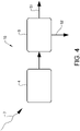
- FIG. 4 shows one embodiment of the device 10 according to the invention.
- the schematically illustrated device 10 comprises a radio receiver 4 mountable on a vehicle 5 for receiving radio signals 7 from a radio transmitter 3 arranged on a work site 1.
- the device 10 further comprises a control unit 9 connectable to the radio receiver 4.
- the control unit 9 which is arrangeable on the vehicle 5 can be a separate unit communicating with a central control unit of the vehicle or be a part of the central control unit.
- the receiver 4 and the control unit 9 are preferably electrically connectable to each other, though also a wire-less connection which enables signals to be transmitted between the receiver and the control unit could be used.
- the control unit can also be integrated in the receiver.
- the control unit suitably comprises program code means for providing the requisite signals (for example the control signals of the method for controlling a vehicle as mentioned hereinafter), these signals could also be provided by means of electrical circuits only.
- the control unit 9 is configured to provide control signals S1 for controlling the vehicle 5 according to a first predetermined vehicle operation condition when the radio receiver 4 receives the radio signals 7 from the radio transmitter 3, whereas the control unit 9 is configured to provide control signals S2 for controlling the vehicle 5 according to a second predetermined vehicle operation condition when the radio receiver 4 not receives the radio signals 7 from the radio transmitter 3.
- the first predetermined vehicle operation condition and the second predetermined vehicle operation condition are different from each other.
- the first predetermined vehicle operation condition and the second predetermined vehicle operation condition can be the allowed vehicle speeds Vz, Vd when the radio receiver 4 receives signals from the radio transmitter and when the radio receiver 4 does not receive signals from the radio transmitter, respectively.
- the speed can be differentiated for vehicles receiving the radio signals 7 as compared to vehicles not receiving the radio signals 7.
- the allowed vehicle speed Vz associated with the first predetermined vehicle operation condition can be a non-restricted speed, enabling the vehicle 5 to be driven in full vehicle speed.
- the allowed vehicle speed Vd associated with the second predetermined vehicle operation condition can be limited.
- a default value of the speed Vd is preferably used for the case the receiver 4 does not receive any signals from the radio transmitter 3.
- a default value could be a vehicle velocity which is considered to involve a very low safety risk to other vehicles and/or persons at the work site, for example 10 km/h or lower. Then the vehicle 5 can easily be braked to standstill if needed. This is very good from a safety perspective, since if the radio connection is lost for some reason the vehicle 5 can be controlled to be automatically braked to the default speed. Any malfunction of the radio transmitter 3 or any receiver 4 only means that the current vehicle(s) will be controlled to low speed operation, which may influence the productivity but not the safety.
- the work site zone 6 can be a high-speed area where the vehicle can move in full speed Vz for maximizing the productivity. This means that operator-controlled working machines or walking persons should usually not be permitted in the work site zone 6 or such presence should occur only in exceptional cases under certain conditions.
- the radio signals can be complemented with a sound or light that can be emitted in the work site zone or on the boarder thereof for warning people from entering the work site zone. Such warning signals can be emitted from one or more of the hereinabove mentioned poles.
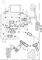
- Fig. 5 is a schematic illustration of a work site 1 provided with a non-claimed system 12.
- the work site 1 is a quarry where stones are loaded onto autonomous haulers 5 at a position A, then transported along a route B and finally dumped by the haulers 5 at a position C.
- the system 12 comprises a plurality of radio transmitters 3 arranged at the work site 1 for transmitting signals.
- the system also comprises radio receivers 4.
- Each of the plurality of autonomous haulers 5 is provided with a radio receiver 4 mounted on the hauler for receiving signals from the radio transmitters 3. It should be stressed that any feature or embodiment of the arrangement and/or the device 10 described herein, or combinations thereof, can be used in the system 12 according to the invention.
- the radio transmitters 3 are arranged to define a work site zone 6 of the work site 1 by means of the coverage of the radio signals from the radio transmitters 3.
- the radio transmitters 3 are arranged spaced apart from each other for creating the work site zone 6.
- the work site zone 6 constitutes an area of the work site comprising route B for transportation of the material from the loading position A to the dumping position C. See the shadowed area within the dotted lines in Fig. 5 .
- a predetermined vehicle operation condition for the autonomous haulers 5 is different in the work site zone 6 when receiving the radio signals from any of the transmitters 3 as compared to outside the work site zone 6 when not receiving any radio signals from the transmitters 3.
- the haulers 5 are allowed to move with full vehicle speed Vz in the work site zone 6, i.e. when travelling along the route B from the loading position A to the dumping position C.
- the speed of the autonomous haulers is restricted, preferably to a maximal velocity of 5-10 km/h.
- the invention also relates to a method for creating a work site zone 6 on a work site 1 according to claim 6.
- the vehicle comprises a radio receiver for receiving radio signals from a radio transmitter arranged on a work site and a control unit for providing control signals to the vehicle.
- the radio receiver and the control unit are connectable to each other.
- the method may comprise identifying 50 if radio signals are received. If YES the method comprises the step of providing 60 control signals S1 for controlling the vehicle according to a first predetermined vehicle operation condition when the radio receiver receives the radio signals from the radio transmitter. If NO the method comprises the step of providing 70 control signals S2 for controlling the vehicle according to a second predetermined vehicle operation condition when the radio receiver not receives the radio signals from the radio transmitter.
Landscapes
- Engineering & Computer Science (AREA)
- Automation & Control Theory (AREA)
- Radar, Positioning & Navigation (AREA)
- Transportation (AREA)
- Mechanical Engineering (AREA)
- Aviation & Aerospace Engineering (AREA)
- Remote Sensing (AREA)
- Physics & Mathematics (AREA)
- General Physics & Mathematics (AREA)
- Human Computer Interaction (AREA)
- Control Of Position, Course, Altitude, Or Attitude Of Moving Bodies (AREA)
- Traffic Control Systems (AREA)
- Operation Control Of Excavators (AREA)
- Selective Calling Equipment (AREA)
Claims (6)
- Anordnung (2) für eine Baustelle (1), die Anordnung (2) umfassend einen Mast, einen an dem Mast befestigten Funksender (3), wobei der Funksender an der Baustelle zum Übertragen von Signalen (7) angeordnet ist, und eine Vorrichtung (10) umfassend, eine Steuereinheit (9) und einen mit der Steuereinheit (9) verbundenen Funkempfänger (4), wobei die Vorrichtung (10) so konfiguriert ist, dass sie auf einem autonom gesteuerten Fahrzeug (5) an der Baustelle (1) angeordnet ist, wobei der Funksender (3) angeordnet ist, um eine Baustellenzone (6) der Baustelle mittels der Abdeckung der Signale (7) von dem Funksender zu definieren, dadurch gekennzeichnet, dass die Steuereinheit (9) konfiguriert ist, um das autonom gesteuerte Fahrzeug so zu steuern, dass es in einem erhöhten Fahrzeugbetriebszustand in der Baustellenzone (6) autonom betrieben wird, wenn der Funkempfänger (4) die Funksignale (7) empfängt, im Vergleich zu außerhalb der Baustellenzone (6), wenn der Funkempfänger (4) die Funksignale (7) nicht empfängt, wobei der Mast eine Warnsignalanordnung umfasst, die konfiguriert ist, um zu verhindern, dass vom Fahrer gesteuerte Fahrzeuge in die Baustellenzone einfahren.
- Anordnung nach Anspruch 1, dadurch gekennzeichnet, dass der Fahrzeugbetriebszustand die zulässige Fahrzeuggeschwindigkeit (Vz) ist.
- Anordnung nach Anspruch 2, dadurch gekennzeichnet, dass die zulässige Fahrzeuggeschwindigkeit (Vz) in der durch den Funksender (3) definierten Baustellenzone (6) höher ist als die zulässige Fahrzeuggeschwindigkeit (Vd) in dem von den Funksignalen (7) nicht abgedeckten Baustellenbereich außerhalb der Baustellenzone (6).
- Anordnung nach Anspruch 2 oder 3, dadurch gekennzeichnet, dass die zulässige Fahrzeuggeschwindigkeit (Vz) in der Baustellenzone (6) eine nicht eingeschränkte Geschwindigkeit ist.
- Anordnung nach einem der vorhergehenden Ansprüche, dadurch gekennzeichnet, dass der Mast (8) bewegbar ist und in verschiedenen Positionen an der Baustelle (1) angeordnet werden kann, so dass die Position des Funksenders (3) sowie die Position der Baustellenzone (6) verändert werden kann.
- Verfahren zur Schaffung einer Baustellenzone (6) auf einer Baustelle (1), dadurch gekennzeichnet, dass es die folgenden Schritte umfasst:- Übertragen von Funksignalen (7) und Warnsignalen auf der Baustelle (1) von einem an einem Mast befestigten und auf der Baustelle angeordneten Funksender (3), wobei die Funksignale von einem auf einem autonom gesteuerten Fahrzeug (5) auf der Baustelle angeordneten Funkempfänger (4) empfangen werden können,- Definieren einer Baustellenzone (6) der Baustelle mittels der Abdeckung der Funksignale (7) des Funksenders (3),- Steuern des autonom gesteuerten Fahrzeugs (5) so, dass es in einem erhöhten Fahrzeugbetriebszustand in der Baustellenzone (6) autonom betrieben wird, wenn der Funkempfänger (4) die Funksignale (7) empfängt, im Vergleich zu außerhalb der Baustellenzone (6), wenn der Funkempfänger (4) die Funksignale (7) nicht empfängt, und- Aussenden von Warnsignalen vom Funksender (3), um zu verhindern, dass vom Fahrer gesteuerte Fahrzeuge in die Baustellenzone einfahren.
Applications Claiming Priority (1)
| Application Number | Priority Date | Filing Date | Title |
|---|---|---|---|
| PCT/SE2016/051165 WO2018097773A1 (en) | 2016-11-24 | 2016-11-24 | An arrangement for differentiated control of vehicles on a work site |
Publications (3)
| Publication Number | Publication Date |
|---|---|
| EP3545378A1 EP3545378A1 (de) | 2019-10-02 |
| EP3545378A4 EP3545378A4 (de) | 2020-06-10 |
| EP3545378B1 true EP3545378B1 (de) | 2022-12-21 |
Family
ID=62196212
Family Applications (1)
| Application Number | Title | Priority Date | Filing Date |
|---|---|---|---|
| EP16922054.8A Active EP3545378B1 (de) | 2016-11-24 | 2016-11-24 | Anordnung zur differenzierten steuerung von fahrzeugen auf einer baustelle |
Country Status (4)
| Country | Link |
|---|---|
| US (1) | US11046334B2 (de) |
| EP (1) | EP3545378B1 (de) |
| CN (1) | CN109964187B (de) |
| WO (1) | WO2018097773A1 (de) |
Families Citing this family (4)
| Publication number | Priority date | Publication date | Assignee | Title |
|---|---|---|---|---|
| DE102019212399B4 (de) * | 2019-08-20 | 2025-05-22 | Zf Friedrichshafen Ag | Verfahren zur Anpassung einer Geschwindigkeit eines autonomen Fahrzeugs |
| US11609562B2 (en) * | 2020-04-27 | 2023-03-21 | Deere & Company | Using generated markings for vehicle control and object avoidance |
| JP2024021826A (ja) * | 2022-08-04 | 2024-02-16 | ヤンマーホールディングス株式会社 | 設定方法、自動走行方法、設定システム、及び設定プログラム |
| US20250370464A1 (en) * | 2024-05-31 | 2025-12-04 | Crown Equipment Corporation | Systems and methods for providing a zone in a covered environment |
Citations (2)
| Publication number | Priority date | Publication date | Assignee | Title |
|---|---|---|---|---|
| EP2476034A2 (de) * | 2009-09-07 | 2012-07-18 | Deutsche Telekom AG | System und verfahren zur sicheren fernsteuerung von fahrzeugen |
| US20120239243A1 (en) * | 2008-04-18 | 2012-09-20 | Steve Medwin | System for accessing information for maintaining and repairing industrial vehicles |
Family Cites Families (27)
| Publication number | Priority date | Publication date | Assignee | Title |
|---|---|---|---|---|
| FR2584197A1 (fr) | 1985-06-26 | 1987-01-02 | Orso Michel D | Systeme de localisation et de guidage automatique par visee optique de balises emettrices codees |
| JP2000339029A (ja) * | 1999-05-31 | 2000-12-08 | Komatsu Ltd | 車両の干渉防止装置 |
| WO2001088827A1 (en) * | 2000-05-15 | 2001-11-22 | Modular Mining Systems, Inc. | Permission system for control of autonomous vehicles |
| US6469638B1 (en) * | 2000-09-30 | 2002-10-22 | Modular Mining Systems, Inc. | Intra-vehicle communications system in a mining vehicle monitoring system |
| DE10259168A1 (de) | 2002-12-18 | 2004-07-08 | Daimlerchrysler Ag | Verfahren zum Steuern wenigstens eines autonom fahrenden Fahrzeugs |
| FI115414B (fi) * | 2003-07-03 | 2005-04-29 | Sandvik Tamrock Oy | Järjestely kaivosajoneuvon sijainnin valvontaan kaivoksessa |
| US7984184B2 (en) * | 2003-10-22 | 2011-07-19 | Leica Geosystems Ag | Method and apparatus for managing information exchanges between apparatus on a worksite |
| JP2005211498A (ja) | 2004-01-30 | 2005-08-11 | Funai Electric Co Ltd | 自走式掃除機 |
| US20050283294A1 (en) * | 2004-06-16 | 2005-12-22 | Lehman Allen A Jr | Method and apparatus for machine guidance at a work site |
| FR2886440B1 (fr) * | 2005-05-30 | 2009-10-02 | Rech S Et D Expl Sminieres Sog | Systeme de detection de pietons et d'obstacles potentiels pour un vehicule evoluant dans un site a forte-activite |
| FI120191B (fi) | 2005-10-03 | 2009-07-31 | Sandvik Tamrock Oy | Menetelmä kaivosajoneuvojen ajamiseksi kaivoksessa ja kuljetusjärjestelmä |
| US9645968B2 (en) * | 2006-09-14 | 2017-05-09 | Crown Equipment Corporation | Multiple zone sensing for materials handling vehicles |
| US9715004B2 (en) | 2009-10-05 | 2017-07-25 | Bae Systems Plc | Radio positioning of a mobile receiver using a virtual positioning reference |
| FI122517B (fi) * | 2009-11-25 | 2012-02-29 | Sandvik Mining & Constr Oy | Radioverkkolaitteisto tiedonsiirron järjestämiseksi kaivosajoneuvoa varten |
| US8744626B2 (en) * | 2010-05-27 | 2014-06-03 | Deere & Company | Managing autonomous machines across multiple areas |
| US20110295423A1 (en) * | 2010-05-27 | 2011-12-01 | Noel Wayne Anderson | Condition based keep-out for machines |
| ES2765012T3 (es) * | 2010-08-23 | 2020-06-05 | Status Tech Pty Ltd | Un sistema de información y alerta de seguridad para vehículos |
| US9195914B2 (en) * | 2012-09-05 | 2015-11-24 | Google Inc. | Construction zone sign detection |
| DE102012024872A1 (de) * | 2012-12-19 | 2014-06-26 | Audi Ag | Funkschlüssel für ein Fahrzeug |
| US9720411B2 (en) | 2014-02-25 | 2017-08-01 | Ford Global Technologies, Llc | Autonomous driving sensing system and method |
| US20140214264A1 (en) | 2014-03-28 | 2014-07-31 | Caterpillar Inc. | Coordinated data transmission triggers |
| RO130446A0 (ro) | 2014-12-10 | 2015-07-30 | Ioana Camelia Barbu | Sistem automat de limitare a vitezei pentru autovehicule, bazat pe etichete radio rf pasive |
| US9649766B2 (en) * | 2015-03-17 | 2017-05-16 | Amazon Technologies, Inc. | Systems and methods to facilitate human/robot interaction |
| US9989636B2 (en) * | 2015-03-26 | 2018-06-05 | Deere & Company | Multi-use detection system for work vehicle |
| BR102016008666B1 (pt) * | 2015-05-12 | 2022-10-11 | Autonomous Solutions, Inc. | Sistema de controle para uma estação-base, método para controlar um veículo agrícola e sistema agrícola autônomo |
| JP6498542B2 (ja) * | 2015-06-17 | 2019-04-10 | 日立建機株式会社 | 管制制御システム及び車載端末装置 |
| AU2015354564B2 (en) * | 2015-11-30 | 2017-11-09 | Komatsu Ltd. | Work machine control system, work machine, work machine management system, and method for controlling work machine |
-
2016
- 2016-11-24 EP EP16922054.8A patent/EP3545378B1/de active Active
- 2016-11-24 WO PCT/SE2016/051165 patent/WO2018097773A1/en not_active Ceased
- 2016-11-24 US US16/462,100 patent/US11046334B2/en active Active
- 2016-11-24 CN CN201680090866.3A patent/CN109964187B/zh not_active Expired - Fee Related
Patent Citations (2)
| Publication number | Priority date | Publication date | Assignee | Title |
|---|---|---|---|---|
| US20120239243A1 (en) * | 2008-04-18 | 2012-09-20 | Steve Medwin | System for accessing information for maintaining and repairing industrial vehicles |
| EP2476034A2 (de) * | 2009-09-07 | 2012-07-18 | Deutsche Telekom AG | System und verfahren zur sicheren fernsteuerung von fahrzeugen |
Also Published As
| Publication number | Publication date |
|---|---|
| WO2018097773A1 (en) | 2018-05-31 |
| EP3545378A4 (de) | 2020-06-10 |
| US20200255032A1 (en) | 2020-08-13 |
| CN109964187A (zh) | 2019-07-02 |
| US11046334B2 (en) | 2021-06-29 |
| CN109964187B (zh) | 2022-09-20 |
| EP3545378A1 (de) | 2019-10-02 |
Similar Documents
| Publication | Publication Date | Title |
|---|---|---|
| US20090043462A1 (en) | Worksite zone mapping and collision avoidance system | |
| EP3545378B1 (de) | Anordnung zur differenzierten steuerung von fahrzeugen auf einer baustelle | |
| US10830392B2 (en) | Mechanized area controller | |
| CA3105776C (en) | A system for controlling a plurality of autonomous vehicles on a mine site | |
| CA3026953C (en) | Use of electronic badges in aisle passing maneuvers | |
| WO2015121818A2 (en) | System for preventing collisions between self-propelled vehicles and obstacles in workplaces or the like | |
| AU2017281901A1 (en) | Electronic badge to authenticate and track industrial vehicle operator | |
| JP2016194481A (ja) | 作業車両用の安全装置及び作業車両の監視方法 | |
| AU2017281539A1 (en) | Electronic badge as a talking marker | |
| WO2015151291A1 (ja) | 交通管制サーバ及びシステム | |
| WO2018032485A1 (zh) | 一种矿山无人运输车队控制系统 | |
| RU2335423C2 (ru) | Рельсовая транспортная система | |
| KR102194654B1 (ko) | 블루투스 비콘 기반의 지하광산 근접 경고 시스템 및 방법 | |
| US12504757B2 (en) | Autonomous vehicle safety system and method | |
| US20120013453A1 (en) | RFID Safety System and Method | |
| WO2004090830A1 (en) | Collision avoidance method and system | |
| JP2021085186A (ja) | 安全制御システム | |
| JP2021085185A (ja) | 安全制御システム | |
| CN115454048A (zh) | 一种煤矿井下运输安全预控方法及系统 | |
| CN117295649A (zh) | 自动驾驶车辆安全系统和方法 | |
| GB2492332A (en) | Safety system having detectors to detect any transponders within a detection zone, and restrict an apparatus in response to detection of a transponder | |
| JP2016115038A (ja) | 重機周りの安全管理方法及びシステム | |
| KR102687340B1 (ko) | 건설장비 인명사고 발생을 방지하기 위한 건설현장 안전관리시스템 | |
| EP4295337B1 (de) | Notdurchgangssystem | |
| WO2002007002A1 (en) | Portable vehicle-tracking module for traffic monitoring |
Legal Events
| Date | Code | Title | Description |
|---|---|---|---|
| STAA | Information on the status of an ep patent application or granted ep patent |
Free format text: STATUS: THE INTERNATIONAL PUBLICATION HAS BEEN MADE |
|
| PUAI | Public reference made under article 153(3) epc to a published international application that has entered the european phase |
Free format text: ORIGINAL CODE: 0009012 |
|
| STAA | Information on the status of an ep patent application or granted ep patent |
Free format text: STATUS: REQUEST FOR EXAMINATION WAS MADE |
|
| 17P | Request for examination filed |
Effective date: 20190619 |
|
| AK | Designated contracting states |
Kind code of ref document: A1 Designated state(s): AL AT BE BG CH CY CZ DE DK EE ES FI FR GB GR HR HU IE IS IT LI LT LU LV MC MK MT NL NO PL PT RO RS SE SI SK SM TR |
|
| AX | Request for extension of the european patent |
Extension state: BA ME |
|
| DAV | Request for validation of the european patent (deleted) | ||
| DAX | Request for extension of the european patent (deleted) | ||
| A4 | Supplementary search report drawn up and despatched |
Effective date: 20200512 |
|
| RIC1 | Information provided on ipc code assigned before grant |
Ipc: G05D 1/02 20200101AFI20200506BHEP Ipc: B60W 60/00 20200101ALI20200506BHEP Ipc: B60W 30/00 20060101ALI20200506BHEP Ipc: B60W 30/14 20060101ALI20200506BHEP |
|
| STAA | Information on the status of an ep patent application or granted ep patent |
Free format text: STATUS: EXAMINATION IS IN PROGRESS |
|
| 17Q | First examination report despatched |
Effective date: 20201026 |
|
| GRAP | Despatch of communication of intention to grant a patent |
Free format text: ORIGINAL CODE: EPIDOSNIGR1 |
|
| STAA | Information on the status of an ep patent application or granted ep patent |
Free format text: STATUS: GRANT OF PATENT IS INTENDED |
|
| INTG | Intention to grant announced |
Effective date: 20220201 |
|
| GRAJ | Information related to disapproval of communication of intention to grant by the applicant or resumption of examination proceedings by the epo deleted |
Free format text: ORIGINAL CODE: EPIDOSDIGR1 |
|
| STAA | Information on the status of an ep patent application or granted ep patent |
Free format text: STATUS: EXAMINATION IS IN PROGRESS |
|
| INTC | Intention to grant announced (deleted) | ||
| GRAS | Grant fee paid |
Free format text: ORIGINAL CODE: EPIDOSNIGR3 |
|
| STAA | Information on the status of an ep patent application or granted ep patent |
Free format text: STATUS: GRANT OF PATENT IS INTENDED |
|
| GRAP | Despatch of communication of intention to grant a patent |
Free format text: ORIGINAL CODE: EPIDOSNIGR1 |
|
| INTG | Intention to grant announced |
Effective date: 20220725 |
|
| GRAA | (expected) grant |
Free format text: ORIGINAL CODE: 0009210 |
|
| STAA | Information on the status of an ep patent application or granted ep patent |
Free format text: STATUS: THE PATENT HAS BEEN GRANTED |
|
| AK | Designated contracting states |
Kind code of ref document: B1 Designated state(s): AL AT BE BG CH CY CZ DE DK EE ES FI FR GB GR HR HU IE IS IT LI LT LU LV MC MK MT NL NO PL PT RO RS SE SI SK SM TR |
|
| REG | Reference to a national code |
Ref country code: GB Ref legal event code: FG4D |
|
| REG | Reference to a national code |
Ref country code: DE Ref legal event code: R096 Ref document number: 602016077078 Country of ref document: DE |
|
| REG | Reference to a national code |
Ref country code: CH Ref legal event code: EP |
|
| REG | Reference to a national code |
Ref country code: AT Ref legal event code: REF Ref document number: 1539426 Country of ref document: AT Kind code of ref document: T Effective date: 20230115 |
|
| REG | Reference to a national code |
Ref country code: IE Ref legal event code: FG4D |
|
| REG | Reference to a national code |
Ref country code: SE Ref legal event code: TRGR |
|
| REG | Reference to a national code |
Ref country code: LT Ref legal event code: MG9D |
|
| REG | Reference to a national code |
Ref country code: NL Ref legal event code: MP Effective date: 20221221 |
|
| PG25 | Lapsed in a contracting state [announced via postgrant information from national office to epo] |
Ref country code: NO Free format text: LAPSE BECAUSE OF FAILURE TO SUBMIT A TRANSLATION OF THE DESCRIPTION OR TO PAY THE FEE WITHIN THE PRESCRIBED TIME-LIMIT Effective date: 20230321 Ref country code: LT Free format text: LAPSE BECAUSE OF FAILURE TO SUBMIT A TRANSLATION OF THE DESCRIPTION OR TO PAY THE FEE WITHIN THE PRESCRIBED TIME-LIMIT Effective date: 20221221 Ref country code: FI Free format text: LAPSE BECAUSE OF FAILURE TO SUBMIT A TRANSLATION OF THE DESCRIPTION OR TO PAY THE FEE WITHIN THE PRESCRIBED TIME-LIMIT Effective date: 20221221 |
|
| REG | Reference to a national code |
Ref country code: AT Ref legal event code: MK05 Ref document number: 1539426 Country of ref document: AT Kind code of ref document: T Effective date: 20221221 |
|
| PG25 | Lapsed in a contracting state [announced via postgrant information from national office to epo] |
Ref country code: RS Free format text: LAPSE BECAUSE OF FAILURE TO SUBMIT A TRANSLATION OF THE DESCRIPTION OR TO PAY THE FEE WITHIN THE PRESCRIBED TIME-LIMIT Effective date: 20221221 Ref country code: LV Free format text: LAPSE BECAUSE OF FAILURE TO SUBMIT A TRANSLATION OF THE DESCRIPTION OR TO PAY THE FEE WITHIN THE PRESCRIBED TIME-LIMIT Effective date: 20221221 Ref country code: HR Free format text: LAPSE BECAUSE OF FAILURE TO SUBMIT A TRANSLATION OF THE DESCRIPTION OR TO PAY THE FEE WITHIN THE PRESCRIBED TIME-LIMIT Effective date: 20221221 Ref country code: GR Free format text: LAPSE BECAUSE OF FAILURE TO SUBMIT A TRANSLATION OF THE DESCRIPTION OR TO PAY THE FEE WITHIN THE PRESCRIBED TIME-LIMIT Effective date: 20230322 |
|
| PG25 | Lapsed in a contracting state [announced via postgrant information from national office to epo] |
Ref country code: NL Free format text: LAPSE BECAUSE OF FAILURE TO SUBMIT A TRANSLATION OF THE DESCRIPTION OR TO PAY THE FEE WITHIN THE PRESCRIBED TIME-LIMIT Effective date: 20221221 |
|
| PG25 | Lapsed in a contracting state [announced via postgrant information from national office to epo] |
Ref country code: SM Free format text: LAPSE BECAUSE OF FAILURE TO SUBMIT A TRANSLATION OF THE DESCRIPTION OR TO PAY THE FEE WITHIN THE PRESCRIBED TIME-LIMIT Effective date: 20221221 Ref country code: RO Free format text: LAPSE BECAUSE OF FAILURE TO SUBMIT A TRANSLATION OF THE DESCRIPTION OR TO PAY THE FEE WITHIN THE PRESCRIBED TIME-LIMIT Effective date: 20221221 Ref country code: PT Free format text: LAPSE BECAUSE OF FAILURE TO SUBMIT A TRANSLATION OF THE DESCRIPTION OR TO PAY THE FEE WITHIN THE PRESCRIBED TIME-LIMIT Effective date: 20230421 Ref country code: ES Free format text: LAPSE BECAUSE OF FAILURE TO SUBMIT A TRANSLATION OF THE DESCRIPTION OR TO PAY THE FEE WITHIN THE PRESCRIBED TIME-LIMIT Effective date: 20221221 Ref country code: EE Free format text: LAPSE BECAUSE OF FAILURE TO SUBMIT A TRANSLATION OF THE DESCRIPTION OR TO PAY THE FEE WITHIN THE PRESCRIBED TIME-LIMIT Effective date: 20221221 Ref country code: CZ Free format text: LAPSE BECAUSE OF FAILURE TO SUBMIT A TRANSLATION OF THE DESCRIPTION OR TO PAY THE FEE WITHIN THE PRESCRIBED TIME-LIMIT Effective date: 20221221 Ref country code: AT Free format text: LAPSE BECAUSE OF FAILURE TO SUBMIT A TRANSLATION OF THE DESCRIPTION OR TO PAY THE FEE WITHIN THE PRESCRIBED TIME-LIMIT Effective date: 20221221 |
|
| PG25 | Lapsed in a contracting state [announced via postgrant information from national office to epo] |
Ref country code: SK Free format text: LAPSE BECAUSE OF FAILURE TO SUBMIT A TRANSLATION OF THE DESCRIPTION OR TO PAY THE FEE WITHIN THE PRESCRIBED TIME-LIMIT Effective date: 20221221 Ref country code: PL Free format text: LAPSE BECAUSE OF FAILURE TO SUBMIT A TRANSLATION OF THE DESCRIPTION OR TO PAY THE FEE WITHIN THE PRESCRIBED TIME-LIMIT Effective date: 20221221 Ref country code: IS Free format text: LAPSE BECAUSE OF FAILURE TO SUBMIT A TRANSLATION OF THE DESCRIPTION OR TO PAY THE FEE WITHIN THE PRESCRIBED TIME-LIMIT Effective date: 20230421 Ref country code: AL Free format text: LAPSE BECAUSE OF FAILURE TO SUBMIT A TRANSLATION OF THE DESCRIPTION OR TO PAY THE FEE WITHIN THE PRESCRIBED TIME-LIMIT Effective date: 20221221 |
|
| REG | Reference to a national code |
Ref country code: DE Ref legal event code: R097 Ref document number: 602016077078 Country of ref document: DE |
|
| PLBE | No opposition filed within time limit |
Free format text: ORIGINAL CODE: 0009261 |
|
| STAA | Information on the status of an ep patent application or granted ep patent |
Free format text: STATUS: NO OPPOSITION FILED WITHIN TIME LIMIT |
|
| PG25 | Lapsed in a contracting state [announced via postgrant information from national office to epo] |
Ref country code: DK Free format text: LAPSE BECAUSE OF FAILURE TO SUBMIT A TRANSLATION OF THE DESCRIPTION OR TO PAY THE FEE WITHIN THE PRESCRIBED TIME-LIMIT Effective date: 20221221 |
|
| REG | Reference to a national code |
Ref country code: DE Ref legal event code: R079 Ref document number: 602016077078 Country of ref document: DE Free format text: PREVIOUS MAIN CLASS: G05D0001020000 Ipc: G05D0001430000 |
|
| 26N | No opposition filed |
Effective date: 20230922 |
|
| PG25 | Lapsed in a contracting state [announced via postgrant information from national office to epo] |
Ref country code: SI Free format text: LAPSE BECAUSE OF FAILURE TO SUBMIT A TRANSLATION OF THE DESCRIPTION OR TO PAY THE FEE WITHIN THE PRESCRIBED TIME-LIMIT Effective date: 20221221 |
|
| PG25 | Lapsed in a contracting state [announced via postgrant information from national office to epo] |
Ref country code: IT Free format text: LAPSE BECAUSE OF FAILURE TO SUBMIT A TRANSLATION OF THE DESCRIPTION OR TO PAY THE FEE WITHIN THE PRESCRIBED TIME-LIMIT Effective date: 20221221 |
|
| REG | Reference to a national code |
Ref country code: CH Ref legal event code: PL |
|
| PG25 | Lapsed in a contracting state [announced via postgrant information from national office to epo] |
Ref country code: MC Free format text: LAPSE BECAUSE OF FAILURE TO SUBMIT A TRANSLATION OF THE DESCRIPTION OR TO PAY THE FEE WITHIN THE PRESCRIBED TIME-LIMIT Effective date: 20221221 |
|
| PG25 | Lapsed in a contracting state [announced via postgrant information from national office to epo] |
Ref country code: LU Free format text: LAPSE BECAUSE OF NON-PAYMENT OF DUE FEES Effective date: 20231124 |
|
| PG25 | Lapsed in a contracting state [announced via postgrant information from national office to epo] |
Ref country code: CH Free format text: LAPSE BECAUSE OF NON-PAYMENT OF DUE FEES Effective date: 20231130 |
|
| GBPC | Gb: european patent ceased through non-payment of renewal fee |
Effective date: 20231124 |
|
| PG25 | Lapsed in a contracting state [announced via postgrant information from national office to epo] |
Ref country code: MC Free format text: LAPSE BECAUSE OF FAILURE TO SUBMIT A TRANSLATION OF THE DESCRIPTION OR TO PAY THE FEE WITHIN THE PRESCRIBED TIME-LIMIT Effective date: 20221221 Ref country code: LU Free format text: LAPSE BECAUSE OF NON-PAYMENT OF DUE FEES Effective date: 20231124 Ref country code: CH Free format text: LAPSE BECAUSE OF NON-PAYMENT OF DUE FEES Effective date: 20231130 |
|
| REG | Reference to a national code |
Ref country code: BE Ref legal event code: MM Effective date: 20231130 |
|
| REG | Reference to a national code |
Ref country code: IE Ref legal event code: MM4A |
|
| PG25 | Lapsed in a contracting state [announced via postgrant information from national office to epo] |
Ref country code: IE Free format text: LAPSE BECAUSE OF NON-PAYMENT OF DUE FEES Effective date: 20231124 |
|
| PG25 | Lapsed in a contracting state [announced via postgrant information from national office to epo] |
Ref country code: GB Free format text: LAPSE BECAUSE OF NON-PAYMENT OF DUE FEES Effective date: 20231124 |
|
| PG25 | Lapsed in a contracting state [announced via postgrant information from national office to epo] |
Ref country code: BE Free format text: LAPSE BECAUSE OF NON-PAYMENT OF DUE FEES Effective date: 20231130 |
|
| PG25 | Lapsed in a contracting state [announced via postgrant information from national office to epo] |
Ref country code: IE Free format text: LAPSE BECAUSE OF NON-PAYMENT OF DUE FEES Effective date: 20231124 Ref country code: GB Free format text: LAPSE BECAUSE OF NON-PAYMENT OF DUE FEES Effective date: 20231124 Ref country code: BE Free format text: LAPSE BECAUSE OF NON-PAYMENT OF DUE FEES Effective date: 20231130 |
|
| PG25 | Lapsed in a contracting state [announced via postgrant information from national office to epo] |
Ref country code: BG Free format text: LAPSE BECAUSE OF FAILURE TO SUBMIT A TRANSLATION OF THE DESCRIPTION OR TO PAY THE FEE WITHIN THE PRESCRIBED TIME-LIMIT Effective date: 20221221 |
|
| PG25 | Lapsed in a contracting state [announced via postgrant information from national office to epo] |
Ref country code: BG Free format text: LAPSE BECAUSE OF FAILURE TO SUBMIT A TRANSLATION OF THE DESCRIPTION OR TO PAY THE FEE WITHIN THE PRESCRIBED TIME-LIMIT Effective date: 20221221 |
|
| PGFP | Annual fee paid to national office [announced via postgrant information from national office to epo] |
Ref country code: FR Payment date: 20241126 Year of fee payment: 9 |
|
| PG25 | Lapsed in a contracting state [announced via postgrant information from national office to epo] |
Ref country code: CY Free format text: LAPSE BECAUSE OF FAILURE TO SUBMIT A TRANSLATION OF THE DESCRIPTION OR TO PAY THE FEE WITHIN THE PRESCRIBED TIME-LIMIT; INVALID AB INITIO Effective date: 20161124 |
|
| PG25 | Lapsed in a contracting state [announced via postgrant information from national office to epo] |
Ref country code: HU Free format text: LAPSE BECAUSE OF FAILURE TO SUBMIT A TRANSLATION OF THE DESCRIPTION OR TO PAY THE FEE WITHIN THE PRESCRIBED TIME-LIMIT; INVALID AB INITIO Effective date: 20161124 |
|
| PG25 | Lapsed in a contracting state [announced via postgrant information from national office to epo] |
Ref country code: TR Free format text: LAPSE BECAUSE OF FAILURE TO SUBMIT A TRANSLATION OF THE DESCRIPTION OR TO PAY THE FEE WITHIN THE PRESCRIBED TIME-LIMIT Effective date: 20221221 |
|
| PGFP | Annual fee paid to national office [announced via postgrant information from national office to epo] |
Ref country code: DE Payment date: 20251126 Year of fee payment: 10 |
|
| PGFP | Annual fee paid to national office [announced via postgrant information from national office to epo] |
Ref country code: SE Payment date: 20251124 Year of fee payment: 10 |