EP3546372A1 - Prérefroidissement de vaporisation de carburant à utiliser avec un inertage catalytique de réservoir de carburant - Google Patents
Prérefroidissement de vaporisation de carburant à utiliser avec un inertage catalytique de réservoir de carburant Download PDFInfo
- Publication number
- EP3546372A1 EP3546372A1 EP19165221.3A EP19165221A EP3546372A1 EP 3546372 A1 EP3546372 A1 EP 3546372A1 EP 19165221 A EP19165221 A EP 19165221A EP 3546372 A1 EP3546372 A1 EP 3546372A1
- Authority
- EP
- European Patent Office
- Prior art keywords
- fuel
- air
- liquid fuel
- vapor
- source
- Prior art date
- Legal status (The legal status is an assumption and is not a legal conclusion. Google has not performed a legal analysis and makes no representation as to the accuracy of the status listed.)
- Granted
Links
Images

Classifications
-
- B—PERFORMING OPERATIONS; TRANSPORTING
- B64—AIRCRAFT; AVIATION; COSMONAUTICS
- B64D—EQUIPMENT FOR FITTING IN OR TO AIRCRAFT; FLIGHT SUITS; PARACHUTES; ARRANGEMENT OR MOUNTING OF POWER PLANTS OR PROPULSION TRANSMISSIONS IN AIRCRAFT
- B64D37/00—Arrangements in connection with fuel supply for power plant
- B64D37/32—Safety measures not otherwise provided for, e.g. preventing explosive conditions
-
- B—PERFORMING OPERATIONS; TRANSPORTING
- B01—PHYSICAL OR CHEMICAL PROCESSES OR APPARATUS IN GENERAL
- B01D—SEPARATION
- B01D53/00—Separation of gases or vapours; Recovering vapours of volatile solvents from gases; Chemical or biological purification of waste gases, e.g. engine exhaust gases, smoke, fumes, flue gases, aerosols
- B01D53/22—Separation of gases or vapours; Recovering vapours of volatile solvents from gases; Chemical or biological purification of waste gases, e.g. engine exhaust gases, smoke, fumes, flue gases, aerosols by diffusion
-
- B—PERFORMING OPERATIONS; TRANSPORTING
- B64—AIRCRAFT; AVIATION; COSMONAUTICS
- B64D—EQUIPMENT FOR FITTING IN OR TO AIRCRAFT; FLIGHT SUITS; PARACHUTES; ARRANGEMENT OR MOUNTING OF POWER PLANTS OR PROPULSION TRANSMISSIONS IN AIRCRAFT
- B64D37/00—Arrangements in connection with fuel supply for power plant
- B64D37/34—Conditioning fuel, e.g. heating
-
- F—MECHANICAL ENGINEERING; LIGHTING; HEATING; WEAPONS; BLASTING
- F02—COMBUSTION ENGINES; HOT-GAS OR COMBUSTION-PRODUCT ENGINE PLANTS
- F02C—GAS-TURBINE PLANTS; AIR INTAKES FOR JET-PROPULSION PLANTS; CONTROLLING FUEL SUPPLY IN AIR-BREATHING JET-PROPULSION PLANTS
- F02C6/00—Plural gas-turbine plants; Combinations of gas-turbine plants with other apparatus; Adaptations of gas-turbine plants for special use
- F02C6/04—Gas-turbine plants providing heated or pressurised working fluid for other apparatus, e.g. without mechanical power output
- F02C6/06—Gas-turbine plants providing heated or pressurised working fluid for other apparatus, e.g. without mechanical power output providing compressed gas
- F02C6/08—Gas-turbine plants providing heated or pressurised working fluid for other apparatus, e.g. without mechanical power output providing compressed gas the gas being bled from the gas-turbine compressor
-
- F—MECHANICAL ENGINEERING; LIGHTING; HEATING; WEAPONS; BLASTING
- F02—COMBUSTION ENGINES; HOT-GAS OR COMBUSTION-PRODUCT ENGINE PLANTS
- F02M—SUPPLYING COMBUSTION ENGINES IN GENERAL WITH COMBUSTIBLE MIXTURES OR CONSTITUENTS THEREOF
- F02M27/00—Apparatus for treating combustion-air, fuel, or fuel-air mixture, by catalysts, electric means, magnetism, rays, sound waves, or the like
- F02M27/02—Apparatus for treating combustion-air, fuel, or fuel-air mixture, by catalysts, electric means, magnetism, rays, sound waves, or the like by catalysts
-
- B—PERFORMING OPERATIONS; TRANSPORTING
- B64—AIRCRAFT; AVIATION; COSMONAUTICS
- B64D—EQUIPMENT FOR FITTING IN OR TO AIRCRAFT; FLIGHT SUITS; PARACHUTES; ARRANGEMENT OR MOUNTING OF POWER PLANTS OR PROPULSION TRANSMISSIONS IN AIRCRAFT
- B64D13/00—Arrangements or adaptations of air-treatment apparatus for aircraft crew or passengers, or freight space
- B64D13/06—Arrangements or adaptations of air-treatment apparatus for aircraft crew or passengers, or freight space the air being conditioned
- B64D2013/0603—Environmental Control Systems
- B64D2013/0618—Environmental Control Systems with arrangements for reducing or managing bleed air, using another air source, e.g. ram air
-
- B—PERFORMING OPERATIONS; TRANSPORTING
- B64—AIRCRAFT; AVIATION; COSMONAUTICS
- B64D—EQUIPMENT FOR FITTING IN OR TO AIRCRAFT; FLIGHT SUITS; PARACHUTES; ARRANGEMENT OR MOUNTING OF POWER PLANTS OR PROPULSION TRANSMISSIONS IN AIRCRAFT
- B64D13/00—Arrangements or adaptations of air-treatment apparatus for aircraft crew or passengers, or freight space
- B64D13/06—Arrangements or adaptations of air-treatment apparatus for aircraft crew or passengers, or freight space the air being conditioned
- B64D2013/0603—Environmental Control Systems
- B64D2013/0659—Environmental Control Systems comprising provisions for cooling fuel systems
Definitions
- the present disclosure relates generally to air inerting systems for aircraft and other applications where an inert gas may be required and, more specifically, to air inerting systems using catalytic oxidation.
- Aircraft fuel tanks can contain potentially combustible combinations of oxygen, fuel vapors, and ignition sources.
- Commercial aviation regulations require actively managing the risk of explosion in the vapor space (i.e., ullage) above the liquid fuel in fuel tanks. This can be accomplished by reducing the oxygen concentration in the ullage by displacing the air in the ullage with an inert gas containing less than 12% oxygen.
- Conventional fuel tank inerting (FTI) methods include air separation module (ASM) methods that utilize hollow fiber membranes to separate ambient air into nitrogen-enriched air, which is directed to fuel tanks, and oxygen-enriched air, which is usually rejected overboard.
- AMS methods rely on bleed air from a compressor stage of an engine, which is not always available in the desired quantity at sufficient pressure.
- a gas inerting system for an aircraft includes a fuel tank configured to contain a liquid fuel, a fuel vaporization system in fluid communication with the fuel tank and configured to receive the liquid fuel from the fuel tank, a source of air in fluid communication with the fuel vaporization system and configured to deliver air into the liquid fuel to produce the fuel vapor, a heat exchanger in fluid communication with the source of air at a location upstream of the fuel vaporization system, and a catalytic oxidation unit in fluid communication with the fuel vaporization system.
- the heat exchanger is configured to cool the air from the air source.
- a fluid connection is configured to deliver the fuel vapor to the catalytic oxidation unit.
- a method for providing fuel vapor to a catalytic oxidation unit of a gas interting system includes cooling pressurized air, injecting the cooled pressurized air into a liquid fuel contained in a vessel, vaporizing a portion of the liquid fuel to produce a fuel vapor in a vapor space of the vessel, and delivering the fuel vapor to the catalytic oxidation unit.
- Catalytic oxidation of fuel is an alternative to traditional air separation modules (ASM) used to produce inert air onboard an aircraft for uses such as fuel tank inerting (FTI) and fire suppression.
- Catalytic oxidation of fuel can leverage a variety of incoming air sources, not limited to bleed air, to produce inert air with oxygen levels below the required 12% oxygen (or 9% for military engines) over a range of conditions.
- a catalyst is used to catalyze a chemical reaction between oxygen (O 2 ) and hydrocarbon fuel to produce carbon dioxide (CO 2 ) and water.
- O 2 oxygen
- CO 2 carbon dioxide
- liquid fuel is available on an aircraft, the fuel delivered to the catalyst for catalytic oxidation must be in a vapor phase.
- Air sparging can be used to volatilize a portion of liquid fuel to produce fuel vapors. Bleed air can be safely used as the sparge gas when the bleed air is cooled prior to sparging to reduce the risk of explosion.
- FIG. 1 is a simplified schematic diagram of inert gas generating system 10, which can be present on-board an aircraft.
- Inert gas generating system 10 includes fuel tank 12, fuel vaporization system 14, air source 16 to deliver air 17, heat exchanger 18, and catalytic oxidation unit (COU) 20.
- Fuel vaporization system 14 is in fluid communication with fuel tank 12 and air source 16 and is configured to receive a portion of liquid fuel 22 from fuel tank 12 and air 17 from air source 16, which is introduced into liquid fuel 22 as a sparge gas to produce fuel vapor 24.
- Air 17 delivered to fuel vaporization system 14 can contain enough oxygen to support combustion. Therefore, to maintain safe conditions, the temperature of air 17 must be kept below the autoignition temperature of fuel 22. This can be achieved by passing air 17 through heat exchanger 18 to be cooled prior to entering fuel vaporization system 14.
- Inert gas generating system 10 can produce a predominantly inert gas by mixing fuel vapor 24 from fuel vaporization system 14 and a source of oxygen, such as air from air source 16, in the presence of a catalyst (i.e., COU 20). Reaction of the hydrocarbon fuel and oxygen in the combustion air produces carbon dioxide and water vapor. The water vapor can be condensed from the exhaust gas exiting COU 20, for example, by heat exchanger 26.
- the carbon dioxide is an inert gas that is mixed with nitrogen naturally found in fresh/ambient air, and which flows through COU 20 unreacted.
- the inert gas and can be directed back to fuel tank 12 to displace gas in ullage 28 and/or can be directed to fire suppression systems (not shown).
- a portion of the inert gas can be recycled back through COU 20 via recycle duct 30 (shown in phantom).
- the catalytic oxidation of fuel is an exothermic reaction, which produces a significant amount of heat.
- the recycle of inert gas can be used to dilute the reactants entering COU 20 as a means to manage the heat produced in COU 20.
- heat can be removed from COU 20 via heat exchange with a cooling source.
- Controller 32 can be operatively coupled (e.g., electrically and/or communicatively) to components shown in FIG. 1 as well as components not depicted (e.g., valves, sensors, etc.) to control operation of inert gas generating system 10.
- Liquid fuel 22 can be kerosene-based jet fuel, such as Jet-A, Jet-Al, or Jet-B fuel.
- liquid fuel 22 can also be a jet propulsion "JP" class fuel, such as JP-5 or JP-8.
- JP jet propulsion
- Other types of fuel such as diesel, gasoline, and mixtures of fuels are also contemplated herein.
- Ullage space 28, which is a vapor space present above liquid fuel 22 in fuel tank 12, can contain potentially combustible fuel vapors.
- System 10 operates to reduce the risk of combustion and explosion within ullage space 28 by providing inert gas to maintain the oxygen concentration within ullage space 26 at or below 12% oxygen by volume for commercial aviation, and below 9% by volume for military applications.
- a portion of liquid fuel 22 is extracted from fuel tank 12 and delivered to fuel vaporization system 14 via fuel delivery passage 33, connecting fuel tank 12 to fuel vaporization system 14.
- One or more valves 34 can be used to control delivery of liquid fuel 22 to fuel vaporization system 14.
- Fuel vaporization system 14 can be located in close proximity to fuel tank 12 or away from fuel tank 12.
- Air source 16 can provide a pressurized source of ambient air, including, but not limited to bleed air from a compressor section of an engine.
- ambient is used to indicate the chemical composition of air 17, not the pressure. Ambient air contains approximately 21% oxygen, which is sufficient for combustion.
- air 17 must be at a temperature below the autoignition temperature of the fuel. The autoignition temperature for most jet fuels is below 230 degree Celsius, but varies depending on fuel type.
- the flow of air 17 to fuel vaporizing system 14 can be controlled by one or more valves 35.
- Heat exchanger 18 is located in fluid communication with air source 16 at a location upstream of fuel vaporization system 14 and is configured to cool air 17 to a temperature below the autoignition temperature of the fuel in fuel vaporization system 14.
- Heat exchanger 18 can be an air-to-air or liquid-to-air heat exchanger as known in the art, utilizing a cooling liquid or cooling air, such as ram air, fan bleed air, air exhausted from a cabin of the aircraft, or other sources capable of sufficiently reducing the temperature of air 17.
- the temperature of air 17 entering heat exchanger 18 can generally range from 80-260 degrees Celsius. Cooled air 17 exiting heat exchanger 18 is delivered to fuel vaporization system 14 as a sparge gas to release fuel vapor 24 from liquid fuel 22.
- Fuel vaporization system 14 includes vessel 36, which is configured to contain liquid fuel 22, delivered from fuel tank 12.
- Vessel 36 includes vapor space 38, which fills the space above the liquid fuel 22.
- Valve 34 can be used to meter delivery of fuel 22, such that liquid fuel 22 does not exceed a defined maximum fill volume so as to ensure vapor space 38 remains available for collection of fuel vapor 24. Delivery of liquid fuel 22 can be controlled by controller 32.
- One or more sensors may be used to detect a volume of liquid fuel 22 in fuel vaporization system 14.
- Fuel vapor 24 is produced by air sparging, in which air 17 is introduced into liquid fuel 22 as small bubbles. The small bubbles of air 17 cause a portion of liquid fuel 22 to volatilize and migrate to vapor space 38.
- Air 17 is delivered through sparging element 40, which is located below the liquid fuel level. As shown in FIG. 1 , sparging element 40 is located at a lowermost section of vessel 36, such that air bubbles 16 travel upwards through a full depth of liquid fuel 22. Sparging element 40 can be a frit, nozzle, or other mechanism as known in the art, capable of producing small bubbles of air 17 in liquid fuel 22. Air 17 delivered through sparging element 40 can be at a pressure between 55.158-413.685 kPa (8-60 psig). Sparging is a fast and effective method for producing fuel vapor 24 and can be conducted safely with air 17 provided the temperature of air 17 is kept below the autoignition temperature of the fuel. A mixture of air 17 and fuel vapor 24 collect in vapor space 38 and can be delivered to COU 20 for inerting.
- COU 20 is fluidly connected to vapor space 38 to allow for delivery of fuel vapor 24 to COU 20.
- a blower or pump 42 can be used to draw fuel vapor 24 from vapor space 38 and force fuel vapor 24 into an inlet of COU 20 for reaction.
- additional combustion air i.e., source of oxygen
- Fuel vaporization system 14 can be continuously operated or operated intermittently to provide on-demand fuel vapor 24 as necessary to meet inert gas needs. Controller 32 is used to control air 17 and liquid fuel 22 entering fuel vaporization system 14. Controller 32 can also be used to adjust flow of fuel vapor 24 from fuel vaporization system 14 to COU 20.
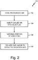
- FIG. 2 provides a flow chart of method 100 for providing fuel vapor 24 to COU 20 for inerting.
- pressurized air 17 is cooled through heat exchanger 18 to reduce the temperature of air 17 below an autoignition temperature of the fuel in fuel vaporizing system 14 (step 102).
- heat exchanger 18 can be an air-to-air or liquid-to-air heat exchanger as known in the art.
- Air 17 can be pressurized ambient air, including but not limited to, bleed air from the compressor section of the engine. Cooled air 17 is directed from heat exchanger 18 to fuel vaporization system 14 for use as a sparge gas. Cooled air 17 is injected or passed into liquid fuel 22 in fuel vaporization system 14 as small bubbles (step 104).
- Cooled air 17 is injected into liquid fuel 22 from below the liquid fuel line, and preferably, near the lowermost portion of vessel 36 such that air bubbles 16 can migrate through a nearly full depth of liquid fuel 22. Cooled air 17 is injected into liquid fuel 22 with a sparging element, which can be a nozzle, frit, or other mechanism as known in the art capable of introducing small air bubbles 16 into liquid fuel 22. A portion of liquid fuel 22 is vaporized as air bubbles 16 migrate through liquid fuel 22, producing fuel vapor 24, which is released into vapor space 38 (step 106). Fuel vapor 24 that has collected in vapor space 38 is delivered to COU 20 for inerting (step 108).
- a sparging element which can be a nozzle, frit, or other mechanism as known in the art capable of introducing small air bubbles 16 into liquid fuel 22.
- a portion of liquid fuel 22 is vaporized as air bubbles 16 migrate through liquid fuel 22, producing fuel vapor 24, which is released into vapor space 38 (step 106). Fuel vapor 24 that has collected
- Gas inerting systems using catalytic reactors can produce inert gas by reacting fuel vapor 24 and oxygen in the presence of a catalyst.
- Air sparging provides a fast and effective means for producing fuel vapor 24 from liquid fuel 22 and can be done safely with engine bleed air 17 containing oxygen if the temperature of air 17 is lowered below an autoignition temperature of the fuel.
- any relative terms or terms of degree used herein such as “substantially”, “essentially”, “generally”, “approximately” and the like, should be interpreted in accordance with and subject to any applicable definitions or limits expressly stated herein. In all instances, any relative terms or terms of degree used herein should be interpreted to broadly encompass any relevant disclosed embodiments as well as such ranges or variations as would be understood by a person of ordinary skill in the art in view of the entirety of the present disclosure. Moreover, any relative terms or terms of degree used herein should be interpreted to encompass a range that expressly includes the designated quality, characteristic, parameter or value, without variation, as if no qualifying relative term or term of degree were utilized in the given disclosure or recitation.
- a gas inerting system for an aircraft includes a fuel tank configured to contain a liquid fuel, a fuel vaporization system in fluid communication with the fuel tank and configured to receive the liquid fuel from the fuel tank, a source of air in fluid communication with the fuel vaporization system and configured to deliver air into the liquid fuel to produce the fuel vapor, a heat exchanger in fluid communication with the source of air at a location upstream of the fuel vaporization system, and a catalytic oxidation unit in fluid communication with the fuel vaporization system.
- the heat exchanger is configured to cool the air from the air source.
- a fluid connection is configured to deliver the fuel vapor to the catalytic oxidation unit.
- gas inerting system of the preceding paragraph can optionally include, additionally and/or alternatively, any one or more of the following features, configurations, and/or additional components:
- the source of air can be disposed to provide a pressurized ambient air.
- the source of air can be disposed to provide a bleed air from a section of the aircraft.
- a fluid connection between the source of air and the fuel vaporization system can be located below a liquid fuel level.
- the fluid connection can include a sparging element configured to deliver the air through the liquid fuel as bubbles and cause a portion of the liquid fuel to volatize to produce the fuel vapor.
- the sparging element can include a frit.
- the sparging element can include a nozzle.
- the fuel vaporization system can include a vapor space.
- the vapor space can be configured to contain the fuel vapor and the air that has passed through the liquid fuel.
- the catalytic oxidation unit can be in fluid communication with the vapor space.
- the heat exchanger can be configured to cool the air to a temperature below an autoignition temperature of the fuel.
- a method for providing fuel vapor to a catalytic oxidation unit of a gas interting system includes cooling pressurized air, injecting the cooled pressurized air into a liquid fuel contained in a vessel, vaporizing a portion of the liquid fuel to produce a fuel vapor in a vapor space of the vessel, and delivering the fuel vapor to the catalytic oxidation unit.
- the method of the preceding paragraph can optionally include, additionally and/or alternatively, any one or more of the following features, configurations, additional components, and/or steps:
- the cooled pressurized air can be injected into the liquid fuel from a location in the vessel below a liquid fuel line.
- the cooled pressurized air can be injected into the liquid fuel through a sparging element configured to deliver bubbles of the air into the liquid fuel.
- the sparging element can include a nozzle or a frit.
- the cooled pressurized air can be bleed air from a compressor section of an aircraft.
- the cooled pressurized air can be cooled to a temperature below an autoignition temperature of the fuel.
Landscapes
- Engineering & Computer Science (AREA)
- Chemical & Material Sciences (AREA)
- Chemical Kinetics & Catalysis (AREA)
- Aviation & Aerospace Engineering (AREA)
- Combustion & Propulsion (AREA)
- Mechanical Engineering (AREA)
- General Engineering & Computer Science (AREA)
- Analytical Chemistry (AREA)
- General Chemical & Material Sciences (AREA)
- Oil, Petroleum & Natural Gas (AREA)
- Separation By Low-Temperature Treatments (AREA)
- Hydrogen, Water And Hydrids (AREA)
Applications Claiming Priority (1)
| Application Number | Priority Date | Filing Date | Title |
|---|---|---|---|
| US15/940,522 US11046449B2 (en) | 2018-03-29 | 2018-03-29 | Precooling for fuel vaporization in use with catalytic fuel tank inerting |
Publications (2)
| Publication Number | Publication Date |
|---|---|
| EP3546372A1 true EP3546372A1 (fr) | 2019-10-02 |
| EP3546372B1 EP3546372B1 (fr) | 2020-05-13 |
Family
ID=65991626
Family Applications (1)
| Application Number | Title | Priority Date | Filing Date |
|---|---|---|---|
| EP19165221.3A Active EP3546372B1 (fr) | 2018-03-29 | 2019-03-26 | Prérefroidissement de vaporisation de carburant à utiliser avec un inertage catalytique de réservoir de carburant |
Country Status (2)
| Country | Link |
|---|---|
| US (1) | US11046449B2 (fr) |
| EP (1) | EP3546372B1 (fr) |
Families Citing this family (3)
| Publication number | Priority date | Publication date | Assignee | Title |
|---|---|---|---|---|
| DE102016219680A1 (de) * | 2016-10-11 | 2018-04-12 | Siemens Aktiengesellschaft | Antriebssystem für ein Fahrzeug mit Verbrennungskraftmaschine und Treibstofftank |
| GB2598778A (en) * | 2020-09-14 | 2022-03-16 | Airbus Operations Ltd | Fuel storage systems |
| CN113135296B (zh) * | 2021-05-14 | 2022-03-08 | 金陵科技学院 | 一种抑制燃油结焦的系统及其工作方法 |
Citations (2)
| Publication number | Priority date | Publication date | Assignee | Title |
|---|---|---|---|---|
| US20080128048A1 (en) * | 2006-11-15 | 2008-06-05 | Honeywell International Inc. | Advanced carbon dioxide fuel tank inerting system |
| EP3279092A1 (fr) * | 2016-08-03 | 2018-02-07 | Hamilton Sundstrand Corporation | Appareil d'inertage de réservoir de carburant catalytique pour aéronef |
Family Cites Families (10)
| Publication number | Priority date | Publication date | Assignee | Title |
|---|---|---|---|---|
| US6315815B1 (en) * | 1999-12-16 | 2001-11-13 | United Technologies Corporation | Membrane based fuel deoxygenator |
| US7081153B2 (en) | 2003-12-02 | 2006-07-25 | Honeywell International Inc. | Gas generating system and method for inerting aircraft fuel tanks |
| JP2009501680A (ja) | 2005-07-08 | 2009-01-22 | ファイア テクノロジーズ、インコーポレイテッド | 触媒反応成分低減システムおよびその使用法 |
| US8015838B2 (en) | 2007-12-21 | 2011-09-13 | Honeywell International Inc. | On-board inert gas generation turbocompressor systems and methods |
| US7896292B2 (en) | 2008-01-16 | 2011-03-01 | Phyre Technologies, Inc. | Reactive component reduction system and methods for the use thereof |
| US8602362B2 (en) * | 2010-10-08 | 2013-12-10 | Simmonds Precision Products, Inc. | System and method for scavenging ullage from center wing tanks in an airplane |
| US9901874B2 (en) | 2015-01-20 | 2018-02-27 | Hamilton Sundstrand Corporation | High temperature air separation system architecture |
| US20170313435A1 (en) | 2016-04-29 | 2017-11-02 | Hamilton Sundstrand Corporation | Fuel tank inerting systems for aircraft |
| US10300431B2 (en) | 2016-05-31 | 2019-05-28 | Hamilton Sundstrant Corporation | On-board vehicle inert gas generation system |
| US10919637B2 (en) | 2016-07-12 | 2021-02-16 | Hamilton Sunstrand Corporation | Temperature control system for fuel tank inerting system |
-
2018
- 2018-03-29 US US15/940,522 patent/US11046449B2/en active Active
-
2019
- 2019-03-26 EP EP19165221.3A patent/EP3546372B1/fr active Active
Patent Citations (2)
| Publication number | Priority date | Publication date | Assignee | Title |
|---|---|---|---|---|
| US20080128048A1 (en) * | 2006-11-15 | 2008-06-05 | Honeywell International Inc. | Advanced carbon dioxide fuel tank inerting system |
| EP3279092A1 (fr) * | 2016-08-03 | 2018-02-07 | Hamilton Sundstrand Corporation | Appareil d'inertage de réservoir de carburant catalytique pour aéronef |
Also Published As
| Publication number | Publication date |
|---|---|
| US20190300196A1 (en) | 2019-10-03 |
| US11046449B2 (en) | 2021-06-29 |
| EP3546372B1 (fr) | 2020-05-13 |
Similar Documents
| Publication | Publication Date | Title |
|---|---|---|
| EP3546372B1 (fr) | Prérefroidissement de vaporisation de carburant à utiliser avec un inertage catalytique de réservoir de carburant | |
| US20180155048A1 (en) | Catalytic fuel tank inerting apparatus for aircraft | |
| EP3441128B1 (fr) | Système et méthode de production de gaz inerte. | |
| US10640227B2 (en) | Catalytic fuel tank inerting apparatus for aircraft | |
| US20180155050A1 (en) | Catalytic fuel tank inerting apparatus for aircraft | |
| US20180222598A1 (en) | Catalytic fuel tank inerting apparatus for aircraft | |
| US20180148188A1 (en) | Catalytic fuel tank inerting apparatus for aircraft | |
| US20180148190A1 (en) | Catalytic fuel tank inerting apparatus for aircraft | |
| US20180148191A1 (en) | Catalytic fuel tank inerting apparatus for aircraft | |
| EP3587276A1 (fr) | Système d'inertage de réservoir de carburant catalytique | |
| EP3543142B1 (fr) | Réacteur de recyclage interne d'inertage catalytique | |
| US20180155047A1 (en) | Catalytic fuel tank inerting apparatus for aircraft | |
| EP3360791B1 (fr) | Dispositif avec un catalysateur pour inertage de reservoirs d'aéronef | |
| US20180148189A1 (en) | Catalytic fuel tank inerting apparatus for aircraft | |
| EP3418200B1 (fr) | Gestion de gaz de produit d'oxydation catalytique | |
| US20190046924A1 (en) | Inert gas generating system | |
| US11472566B2 (en) | Catalyst decay monitoring of catalytic inerting system | |
| EP3539901B1 (fr) | Mise en service d'un système de génération de gaz d'inertage catalytique avec recyclage pour avion | |
| US11628947B2 (en) | Catalytic fuel tank inerting apparatus for aircraft | |
| EP3539880B1 (fr) | Atténuation de la cavitation dans des systèmes d'inertage de réservoir de carburant à oxydation catalytique |
Legal Events
| Date | Code | Title | Description |
|---|---|---|---|
| PUAI | Public reference made under article 153(3) epc to a published international application that has entered the european phase |
Free format text: ORIGINAL CODE: 0009012 |
|
| STAA | Information on the status of an ep patent application or granted ep patent |
Free format text: STATUS: THE APPLICATION HAS BEEN PUBLISHED |
|
| AK | Designated contracting states |
Kind code of ref document: A1 Designated state(s): AL AT BE BG CH CY CZ DE DK EE ES FI FR GB GR HR HU IE IS IT LI LT LU LV MC MK MT NL NO PL PT RO RS SE SI SK SM TR |
|
| AX | Request for extension of the european patent |
Extension state: BA ME |
|
| STAA | Information on the status of an ep patent application or granted ep patent |
Free format text: STATUS: REQUEST FOR EXAMINATION WAS MADE |
|
| 17P | Request for examination filed |
Effective date: 20191121 |
|
| RBV | Designated contracting states (corrected) |
Designated state(s): AL AT BE BG CH CY CZ DE DK EE ES FI FR GB GR HR HU IE IS IT LI LT LU LV MC MK MT NL NO PL PT RO RS SE SI SK SM TR |
|
| RIC1 | Information provided on ipc code assigned before grant |
Ipc: B01D 53/00 20060101ALI20191210BHEP Ipc: B64D 37/32 20060101AFI20191210BHEP |
|
| GRAP | Despatch of communication of intention to grant a patent |
Free format text: ORIGINAL CODE: EPIDOSNIGR1 |
|
| STAA | Information on the status of an ep patent application or granted ep patent |
Free format text: STATUS: GRANT OF PATENT IS INTENDED |
|
| INTG | Intention to grant announced |
Effective date: 20200117 |
|
| RIN1 | Information on inventor provided before grant (corrected) |
Inventor name: SURAWSKI, ERIC |
|
| GRAS | Grant fee paid |
Free format text: ORIGINAL CODE: EPIDOSNIGR3 |
|
| GRAA | (expected) grant |
Free format text: ORIGINAL CODE: 0009210 |
|
| STAA | Information on the status of an ep patent application or granted ep patent |
Free format text: STATUS: THE PATENT HAS BEEN GRANTED |
|
| AK | Designated contracting states |
Kind code of ref document: B1 Designated state(s): AL AT BE BG CH CY CZ DE DK EE ES FI FR GB GR HR HU IE IS IT LI LT LU LV MC MK MT NL NO PL PT RO RS SE SI SK SM TR |
|
| REG | Reference to a national code |
Ref country code: GB Ref legal event code: FG4D |
|
| REG | Reference to a national code |
Ref country code: CH Ref legal event code: EP |
|
| REG | Reference to a national code |
Ref country code: DE Ref legal event code: R096 Ref document number: 602019000115 Country of ref document: DE |
|
| REG | Reference to a national code |
Ref country code: AT Ref legal event code: REF Ref document number: 1269960 Country of ref document: AT Kind code of ref document: T Effective date: 20200615 |
|
| REG | Reference to a national code |
Ref country code: LT Ref legal event code: MG4D |
|
| REG | Reference to a national code |
Ref country code: NL Ref legal event code: MP Effective date: 20200513 |
|
| PG25 | Lapsed in a contracting state [announced via postgrant information from national office to epo] |
Ref country code: SE Free format text: LAPSE BECAUSE OF FAILURE TO SUBMIT A TRANSLATION OF THE DESCRIPTION OR TO PAY THE FEE WITHIN THE PRESCRIBED TIME-LIMIT Effective date: 20200513 Ref country code: LT Free format text: LAPSE BECAUSE OF FAILURE TO SUBMIT A TRANSLATION OF THE DESCRIPTION OR TO PAY THE FEE WITHIN THE PRESCRIBED TIME-LIMIT Effective date: 20200513 Ref country code: IS Free format text: LAPSE BECAUSE OF FAILURE TO SUBMIT A TRANSLATION OF THE DESCRIPTION OR TO PAY THE FEE WITHIN THE PRESCRIBED TIME-LIMIT Effective date: 20200913 Ref country code: NO Free format text: LAPSE BECAUSE OF FAILURE TO SUBMIT A TRANSLATION OF THE DESCRIPTION OR TO PAY THE FEE WITHIN THE PRESCRIBED TIME-LIMIT Effective date: 20200813 Ref country code: GR Free format text: LAPSE BECAUSE OF FAILURE TO SUBMIT A TRANSLATION OF THE DESCRIPTION OR TO PAY THE FEE WITHIN THE PRESCRIBED TIME-LIMIT Effective date: 20200814 Ref country code: PT Free format text: LAPSE BECAUSE OF FAILURE TO SUBMIT A TRANSLATION OF THE DESCRIPTION OR TO PAY THE FEE WITHIN THE PRESCRIBED TIME-LIMIT Effective date: 20200914 Ref country code: FI Free format text: LAPSE BECAUSE OF FAILURE TO SUBMIT A TRANSLATION OF THE DESCRIPTION OR TO PAY THE FEE WITHIN THE PRESCRIBED TIME-LIMIT Effective date: 20200513 |
|
| PG25 | Lapsed in a contracting state [announced via postgrant information from national office to epo] |
Ref country code: LV Free format text: LAPSE BECAUSE OF FAILURE TO SUBMIT A TRANSLATION OF THE DESCRIPTION OR TO PAY THE FEE WITHIN THE PRESCRIBED TIME-LIMIT Effective date: 20200513 Ref country code: HR Free format text: LAPSE BECAUSE OF FAILURE TO SUBMIT A TRANSLATION OF THE DESCRIPTION OR TO PAY THE FEE WITHIN THE PRESCRIBED TIME-LIMIT Effective date: 20200513 Ref country code: BG Free format text: LAPSE BECAUSE OF FAILURE TO SUBMIT A TRANSLATION OF THE DESCRIPTION OR TO PAY THE FEE WITHIN THE PRESCRIBED TIME-LIMIT Effective date: 20200813 Ref country code: RS Free format text: LAPSE BECAUSE OF FAILURE TO SUBMIT A TRANSLATION OF THE DESCRIPTION OR TO PAY THE FEE WITHIN THE PRESCRIBED TIME-LIMIT Effective date: 20200513 |
|
| REG | Reference to a national code |
Ref country code: AT Ref legal event code: MK05 Ref document number: 1269960 Country of ref document: AT Kind code of ref document: T Effective date: 20200513 |
|
| PG25 | Lapsed in a contracting state [announced via postgrant information from national office to epo] |
Ref country code: NL Free format text: LAPSE BECAUSE OF FAILURE TO SUBMIT A TRANSLATION OF THE DESCRIPTION OR TO PAY THE FEE WITHIN THE PRESCRIBED TIME-LIMIT Effective date: 20200513 Ref country code: AL Free format text: LAPSE BECAUSE OF FAILURE TO SUBMIT A TRANSLATION OF THE DESCRIPTION OR TO PAY THE FEE WITHIN THE PRESCRIBED TIME-LIMIT Effective date: 20200513 |
|
| PG25 | Lapsed in a contracting state [announced via postgrant information from national office to epo] |
Ref country code: RO Free format text: LAPSE BECAUSE OF FAILURE TO SUBMIT A TRANSLATION OF THE DESCRIPTION OR TO PAY THE FEE WITHIN THE PRESCRIBED TIME-LIMIT Effective date: 20200513 Ref country code: CZ Free format text: LAPSE BECAUSE OF FAILURE TO SUBMIT A TRANSLATION OF THE DESCRIPTION OR TO PAY THE FEE WITHIN THE PRESCRIBED TIME-LIMIT Effective date: 20200513 Ref country code: ES Free format text: LAPSE BECAUSE OF FAILURE TO SUBMIT A TRANSLATION OF THE DESCRIPTION OR TO PAY THE FEE WITHIN THE PRESCRIBED TIME-LIMIT Effective date: 20200513 Ref country code: AT Free format text: LAPSE BECAUSE OF FAILURE TO SUBMIT A TRANSLATION OF THE DESCRIPTION OR TO PAY THE FEE WITHIN THE PRESCRIBED TIME-LIMIT Effective date: 20200513 Ref country code: SM Free format text: LAPSE BECAUSE OF FAILURE TO SUBMIT A TRANSLATION OF THE DESCRIPTION OR TO PAY THE FEE WITHIN THE PRESCRIBED TIME-LIMIT Effective date: 20200513 Ref country code: EE Free format text: LAPSE BECAUSE OF FAILURE TO SUBMIT A TRANSLATION OF THE DESCRIPTION OR TO PAY THE FEE WITHIN THE PRESCRIBED TIME-LIMIT Effective date: 20200513 Ref country code: IT Free format text: LAPSE BECAUSE OF FAILURE TO SUBMIT A TRANSLATION OF THE DESCRIPTION OR TO PAY THE FEE WITHIN THE PRESCRIBED TIME-LIMIT Effective date: 20200513 Ref country code: DK Free format text: LAPSE BECAUSE OF FAILURE TO SUBMIT A TRANSLATION OF THE DESCRIPTION OR TO PAY THE FEE WITHIN THE PRESCRIBED TIME-LIMIT Effective date: 20200513 |
|
| REG | Reference to a national code |
Ref country code: DE Ref legal event code: R097 Ref document number: 602019000115 Country of ref document: DE |
|
| PG25 | Lapsed in a contracting state [announced via postgrant information from national office to epo] |
Ref country code: SK Free format text: LAPSE BECAUSE OF FAILURE TO SUBMIT A TRANSLATION OF THE DESCRIPTION OR TO PAY THE FEE WITHIN THE PRESCRIBED TIME-LIMIT Effective date: 20200513 Ref country code: PL Free format text: LAPSE BECAUSE OF FAILURE TO SUBMIT A TRANSLATION OF THE DESCRIPTION OR TO PAY THE FEE WITHIN THE PRESCRIBED TIME-LIMIT Effective date: 20200513 |
|
| PLBE | No opposition filed within time limit |
Free format text: ORIGINAL CODE: 0009261 |
|
| STAA | Information on the status of an ep patent application or granted ep patent |
Free format text: STATUS: NO OPPOSITION FILED WITHIN TIME LIMIT |
|
| 26N | No opposition filed |
Effective date: 20210216 |
|
| PG25 | Lapsed in a contracting state [announced via postgrant information from national office to epo] |
Ref country code: MC Free format text: LAPSE BECAUSE OF FAILURE TO SUBMIT A TRANSLATION OF THE DESCRIPTION OR TO PAY THE FEE WITHIN THE PRESCRIBED TIME-LIMIT Effective date: 20200513 |
|
| REG | Reference to a national code |
Ref country code: BE Ref legal event code: MM Effective date: 20210331 |
|
| PG25 | Lapsed in a contracting state [announced via postgrant information from national office to epo] |
Ref country code: IE Free format text: LAPSE BECAUSE OF NON-PAYMENT OF DUE FEES Effective date: 20210326 Ref country code: LU Free format text: LAPSE BECAUSE OF NON-PAYMENT OF DUE FEES Effective date: 20210326 |
|
| PG25 | Lapsed in a contracting state [announced via postgrant information from national office to epo] |
Ref country code: BE Free format text: LAPSE BECAUSE OF NON-PAYMENT OF DUE FEES Effective date: 20210331 |
|
| REG | Reference to a national code |
Ref country code: CH Ref legal event code: PL |
|
| PG25 | Lapsed in a contracting state [announced via postgrant information from national office to epo] |
Ref country code: LI Free format text: LAPSE BECAUSE OF NON-PAYMENT OF DUE FEES Effective date: 20220331 Ref country code: CH Free format text: LAPSE BECAUSE OF NON-PAYMENT OF DUE FEES Effective date: 20220331 |
|
| P01 | Opt-out of the competence of the unified patent court (upc) registered |
Effective date: 20230522 |
|
| PG25 | Lapsed in a contracting state [announced via postgrant information from national office to epo] |
Ref country code: CY Free format text: LAPSE BECAUSE OF FAILURE TO SUBMIT A TRANSLATION OF THE DESCRIPTION OR TO PAY THE FEE WITHIN THE PRESCRIBED TIME-LIMIT Effective date: 20200513 |
|
| PG25 | Lapsed in a contracting state [announced via postgrant information from national office to epo] |
Ref country code: HU Free format text: LAPSE BECAUSE OF FAILURE TO SUBMIT A TRANSLATION OF THE DESCRIPTION OR TO PAY THE FEE WITHIN THE PRESCRIBED TIME-LIMIT; INVALID AB INITIO Effective date: 20190326 |
|
| PG25 | Lapsed in a contracting state [announced via postgrant information from national office to epo] |
Ref country code: SI Free format text: LAPSE BECAUSE OF FAILURE TO SUBMIT A TRANSLATION OF THE DESCRIPTION OR TO PAY THE FEE WITHIN THE PRESCRIBED TIME-LIMIT Effective date: 20200513 |
|
| PG25 | Lapsed in a contracting state [announced via postgrant information from national office to epo] |
Ref country code: MK Free format text: LAPSE BECAUSE OF FAILURE TO SUBMIT A TRANSLATION OF THE DESCRIPTION OR TO PAY THE FEE WITHIN THE PRESCRIBED TIME-LIMIT Effective date: 20200513 |
|
| PG25 | Lapsed in a contracting state [announced via postgrant information from national office to epo] |
Ref country code: TR Free format text: LAPSE BECAUSE OF FAILURE TO SUBMIT A TRANSLATION OF THE DESCRIPTION OR TO PAY THE FEE WITHIN THE PRESCRIBED TIME-LIMIT Effective date: 20200513 |
|
| PG25 | Lapsed in a contracting state [announced via postgrant information from national office to epo] |
Ref country code: MT Free format text: LAPSE BECAUSE OF FAILURE TO SUBMIT A TRANSLATION OF THE DESCRIPTION OR TO PAY THE FEE WITHIN THE PRESCRIBED TIME-LIMIT Effective date: 20200513 |
|
| PGFP | Annual fee paid to national office [announced via postgrant information from national office to epo] |
Ref country code: GB Payment date: 20260219 Year of fee payment: 8 |
|
| PGFP | Annual fee paid to national office [announced via postgrant information from national office to epo] |
Ref country code: DE Payment date: 20260219 Year of fee payment: 8 |
|
| PGFP | Annual fee paid to national office [announced via postgrant information from national office to epo] |
Ref country code: FR Payment date: 20260220 Year of fee payment: 8 |