EP3546802B1 - Véhicule équipé d'une transmission - Google Patents
Véhicule équipé d'une transmission Download PDFInfo
- Publication number
- EP3546802B1 EP3546802B1 EP19152864.5A EP19152864A EP3546802B1 EP 3546802 B1 EP3546802 B1 EP 3546802B1 EP 19152864 A EP19152864 A EP 19152864A EP 3546802 B1 EP3546802 B1 EP 3546802B1
- Authority
- EP
- European Patent Office
- Prior art keywords
- transmission
- shift
- driving force
- actuator
- shift operation
- Prior art date
- Legal status (The legal status is an assumption and is not a legal conclusion. Google has not performed a legal analysis and makes no representation as to the accuracy of the status listed.)
- Active
Links
Images




Classifications
-
- B—PERFORMING OPERATIONS; TRANSPORTING
- B60—VEHICLES IN GENERAL
- B60W—CONJOINT CONTROL OF VEHICLE SUB-UNITS OF DIFFERENT TYPE OR DIFFERENT FUNCTION; CONTROL SYSTEMS SPECIALLY ADAPTED FOR HYBRID VEHICLES; ROAD VEHICLE DRIVE CONTROL SYSTEMS FOR PURPOSES NOT RELATED TO THE CONTROL OF A PARTICULAR SUB-UNIT
- B60W10/00—Conjoint control of vehicle sub-units of different type or different function
- B60W10/02—Conjoint control of vehicle sub-units of different type or different function including control of driveline clutches
-
- B—PERFORMING OPERATIONS; TRANSPORTING
- B60—VEHICLES IN GENERAL
- B60W—CONJOINT CONTROL OF VEHICLE SUB-UNITS OF DIFFERENT TYPE OR DIFFERENT FUNCTION; CONTROL SYSTEMS SPECIALLY ADAPTED FOR HYBRID VEHICLES; ROAD VEHICLE DRIVE CONTROL SYSTEMS FOR PURPOSES NOT RELATED TO THE CONTROL OF A PARTICULAR SUB-UNIT
- B60W10/00—Conjoint control of vehicle sub-units of different type or different function
- B60W10/04—Conjoint control of vehicle sub-units of different type or different function including control of propulsion units
- B60W10/06—Conjoint control of vehicle sub-units of different type or different function including control of propulsion units including control of combustion engines
-
- B—PERFORMING OPERATIONS; TRANSPORTING
- B60—VEHICLES IN GENERAL
- B60W—CONJOINT CONTROL OF VEHICLE SUB-UNITS OF DIFFERENT TYPE OR DIFFERENT FUNCTION; CONTROL SYSTEMS SPECIALLY ADAPTED FOR HYBRID VEHICLES; ROAD VEHICLE DRIVE CONTROL SYSTEMS FOR PURPOSES NOT RELATED TO THE CONTROL OF A PARTICULAR SUB-UNIT
- B60W10/00—Conjoint control of vehicle sub-units of different type or different function
- B60W10/10—Conjoint control of vehicle sub-units of different type or different function including control of change-speed gearings
- B60W10/11—Stepped gearings
-
- B—PERFORMING OPERATIONS; TRANSPORTING
- B60—VEHICLES IN GENERAL
- B60W—CONJOINT CONTROL OF VEHICLE SUB-UNITS OF DIFFERENT TYPE OR DIFFERENT FUNCTION; CONTROL SYSTEMS SPECIALLY ADAPTED FOR HYBRID VEHICLES; ROAD VEHICLE DRIVE CONTROL SYSTEMS FOR PURPOSES NOT RELATED TO THE CONTROL OF A PARTICULAR SUB-UNIT
- B60W30/00—Purposes of road vehicle drive control systems not related to the control of a particular sub-unit, e.g. of systems using conjoint control of vehicle sub-units
- B60W30/18—Propelling the vehicle
- B60W30/18009—Propelling the vehicle related to particular drive situations
- B60W30/18027—Drive off, accelerating from standstill
-
- B—PERFORMING OPERATIONS; TRANSPORTING
- B60—VEHICLES IN GENERAL
- B60W—CONJOINT CONTROL OF VEHICLE SUB-UNITS OF DIFFERENT TYPE OR DIFFERENT FUNCTION; CONTROL SYSTEMS SPECIALLY ADAPTED FOR HYBRID VEHICLES; ROAD VEHICLE DRIVE CONTROL SYSTEMS FOR PURPOSES NOT RELATED TO THE CONTROL OF A PARTICULAR SUB-UNIT
- B60W30/00—Purposes of road vehicle drive control systems not related to the control of a particular sub-unit, e.g. of systems using conjoint control of vehicle sub-units
- B60W30/18—Propelling the vehicle
- B60W30/19—Improvement of gear change, e.g. by synchronisation or smoothing gear shift
-
- F—MECHANICAL ENGINEERING; LIGHTING; HEATING; WEAPONS; BLASTING
- F16—ENGINEERING ELEMENTS AND UNITS; GENERAL MEASURES FOR PRODUCING AND MAINTAINING EFFECTIVE FUNCTIONING OF MACHINES OR INSTALLATIONS; THERMAL INSULATION IN GENERAL
- F16H—GEARING
- F16H61/00—Control functions within control units of change-speed- or reversing-gearings for conveying rotary motion ; Control of exclusively fluid gearing, friction gearing, gearings with endless flexible members or other particular types of gearing
- F16H61/02—Control functions within control units of change-speed- or reversing-gearings for conveying rotary motion ; Control of exclusively fluid gearing, friction gearing, gearings with endless flexible members or other particular types of gearing characterised by the signals used
- F16H61/0202—Control functions within control units of change-speed- or reversing-gearings for conveying rotary motion ; Control of exclusively fluid gearing, friction gearing, gearings with endless flexible members or other particular types of gearing characterised by the signals used the signals being electric
- F16H61/0248—Control units where shifting is directly initiated by the driver, e.g. semi-automatic transmissions
-
- F—MECHANICAL ENGINEERING; LIGHTING; HEATING; WEAPONS; BLASTING
- F16—ENGINEERING ELEMENTS AND UNITS; GENERAL MEASURES FOR PRODUCING AND MAINTAINING EFFECTIVE FUNCTIONING OF MACHINES OR INSTALLATIONS; THERMAL INSULATION IN GENERAL
- F16H—GEARING
- F16H61/00—Control functions within control units of change-speed- or reversing-gearings for conveying rotary motion ; Control of exclusively fluid gearing, friction gearing, gearings with endless flexible members or other particular types of gearing
- F16H61/26—Generation or transmission of movements for final actuating mechanisms
-
- F—MECHANICAL ENGINEERING; LIGHTING; HEATING; WEAPONS; BLASTING
- F16—ENGINEERING ELEMENTS AND UNITS; GENERAL MEASURES FOR PRODUCING AND MAINTAINING EFFECTIVE FUNCTIONING OF MACHINES OR INSTALLATIONS; THERMAL INSULATION IN GENERAL
- F16H—GEARING
- F16H61/00—Control functions within control units of change-speed- or reversing-gearings for conveying rotary motion ; Control of exclusively fluid gearing, friction gearing, gearings with endless flexible members or other particular types of gearing
- F16H61/26—Generation or transmission of movements for final actuating mechanisms
- F16H61/28—Generation or transmission of movements for final actuating mechanisms with at least one movement of the final actuating mechanism being caused by a non-mechanical force, e.g. power-assisted
- F16H61/32—Electric motors , actuators or related electrical control means therefor
-
- F—MECHANICAL ENGINEERING; LIGHTING; HEATING; WEAPONS; BLASTING
- F16—ENGINEERING ELEMENTS AND UNITS; GENERAL MEASURES FOR PRODUCING AND MAINTAINING EFFECTIVE FUNCTIONING OF MACHINES OR INSTALLATIONS; THERMAL INSULATION IN GENERAL
- F16H—GEARING
- F16H63/00—Control outputs from the control unit to change-speed- or reversing-gearings for conveying rotary motion or to other devices than the final output mechanism
- F16H63/02—Final output mechanisms therefor; Actuating means for the final output mechanisms
- F16H63/08—Multiple final output mechanisms being moved by a single common final actuating mechanism
- F16H63/16—Multiple final output mechanisms being moved by a single common final actuating mechanism the final output mechanisms being successively actuated by progressive movement of the final actuating mechanism
-
- F—MECHANICAL ENGINEERING; LIGHTING; HEATING; WEAPONS; BLASTING
- F16—ENGINEERING ELEMENTS AND UNITS; GENERAL MEASURES FOR PRODUCING AND MAINTAINING EFFECTIVE FUNCTIONING OF MACHINES OR INSTALLATIONS; THERMAL INSULATION IN GENERAL
- F16H—GEARING
- F16H63/00—Control outputs from the control unit to change-speed- or reversing-gearings for conveying rotary motion or to other devices than the final output mechanism
- F16H63/40—Control outputs from the control unit to change-speed- or reversing-gearings for conveying rotary motion or to other devices than the final output mechanism comprising signals other than signals for actuating the final output mechanisms
- F16H63/46—Signals to a clutch outside the gearbox
-
- F—MECHANICAL ENGINEERING; LIGHTING; HEATING; WEAPONS; BLASTING
- F16—ENGINEERING ELEMENTS AND UNITS; GENERAL MEASURES FOR PRODUCING AND MAINTAINING EFFECTIVE FUNCTIONING OF MACHINES OR INSTALLATIONS; THERMAL INSULATION IN GENERAL
- F16H—GEARING
- F16H63/00—Control outputs from the control unit to change-speed- or reversing-gearings for conveying rotary motion or to other devices than the final output mechanism
- F16H63/40—Control outputs from the control unit to change-speed- or reversing-gearings for conveying rotary motion or to other devices than the final output mechanism comprising signals other than signals for actuating the final output mechanisms
- F16H63/50—Signals to an engine or motor
- F16H63/502—Signals to an engine or motor for smoothing gear shifts
-
- B—PERFORMING OPERATIONS; TRANSPORTING
- B60—VEHICLES IN GENERAL
- B60W—CONJOINT CONTROL OF VEHICLE SUB-UNITS OF DIFFERENT TYPE OR DIFFERENT FUNCTION; CONTROL SYSTEMS SPECIALLY ADAPTED FOR HYBRID VEHICLES; ROAD VEHICLE DRIVE CONTROL SYSTEMS FOR PURPOSES NOT RELATED TO THE CONTROL OF A PARTICULAR SUB-UNIT
- B60W2300/00—Indexing codes relating to the type of vehicle
- B60W2300/36—Cycles; Motorcycles; Scooters
-
- B—PERFORMING OPERATIONS; TRANSPORTING
- B60—VEHICLES IN GENERAL
- B60W—CONJOINT CONTROL OF VEHICLE SUB-UNITS OF DIFFERENT TYPE OR DIFFERENT FUNCTION; CONTROL SYSTEMS SPECIALLY ADAPTED FOR HYBRID VEHICLES; ROAD VEHICLE DRIVE CONTROL SYSTEMS FOR PURPOSES NOT RELATED TO THE CONTROL OF A PARTICULAR SUB-UNIT
- B60W2510/00—Input parameters relating to a particular sub-units
- B60W2510/06—Combustion engines, Gas turbines
- B60W2510/0638—Engine speed
- B60W2510/0652—Speed change rate
-
- B—PERFORMING OPERATIONS; TRANSPORTING
- B60—VEHICLES IN GENERAL
- B60W—CONJOINT CONTROL OF VEHICLE SUB-UNITS OF DIFFERENT TYPE OR DIFFERENT FUNCTION; CONTROL SYSTEMS SPECIALLY ADAPTED FOR HYBRID VEHICLES; ROAD VEHICLE DRIVE CONTROL SYSTEMS FOR PURPOSES NOT RELATED TO THE CONTROL OF A PARTICULAR SUB-UNIT
- B60W2710/00—Output or target parameters relating to a particular sub-units
- B60W2710/02—Clutches
- B60W2710/021—Clutch engagement state
-
- B—PERFORMING OPERATIONS; TRANSPORTING
- B60—VEHICLES IN GENERAL
- B60W—CONJOINT CONTROL OF VEHICLE SUB-UNITS OF DIFFERENT TYPE OR DIFFERENT FUNCTION; CONTROL SYSTEMS SPECIALLY ADAPTED FOR HYBRID VEHICLES; ROAD VEHICLE DRIVE CONTROL SYSTEMS FOR PURPOSES NOT RELATED TO THE CONTROL OF A PARTICULAR SUB-UNIT
- B60W2710/00—Output or target parameters relating to a particular sub-units
- B60W2710/06—Combustion engines, Gas turbines
- B60W2710/0644—Engine speed
- B60W2710/0661—Speed change rate
-
- B—PERFORMING OPERATIONS; TRANSPORTING
- B60—VEHICLES IN GENERAL
- B60Y—INDEXING SCHEME RELATING TO ASPECTS CROSS-CUTTING VEHICLE TECHNOLOGY
- B60Y2200/00—Type of vehicle
- B60Y2200/10—Road Vehicles
- B60Y2200/12—Motorcycles, Trikes; Quads; Scooters
-
- F—MECHANICAL ENGINEERING; LIGHTING; HEATING; WEAPONS; BLASTING
- F16—ENGINEERING ELEMENTS AND UNITS; GENERAL MEASURES FOR PRODUCING AND MAINTAINING EFFECTIVE FUNCTIONING OF MACHINES OR INSTALLATIONS; THERMAL INSULATION IN GENERAL
- F16H—GEARING
- F16H59/00—Control inputs to control units of change-speed- or reversing-gearings for conveying rotary motion
- F16H59/02—Selector apparatus
- F16H2059/0234—Selectors for gearings using foot control
-
- F—MECHANICAL ENGINEERING; LIGHTING; HEATING; WEAPONS; BLASTING
- F16—ENGINEERING ELEMENTS AND UNITS; GENERAL MEASURES FOR PRODUCING AND MAINTAINING EFFECTIVE FUNCTIONING OF MACHINES OR INSTALLATIONS; THERMAL INSULATION IN GENERAL
- F16H—GEARING
- F16H61/00—Control functions within control units of change-speed- or reversing-gearings for conveying rotary motion ; Control of exclusively fluid gearing, friction gearing, gearings with endless flexible members or other particular types of gearing
- F16H61/26—Generation or transmission of movements for final actuating mechanisms
- F16H61/28—Generation or transmission of movements for final actuating mechanisms with at least one movement of the final actuating mechanism being caused by a non-mechanical force, e.g. power-assisted
- F16H61/32—Electric motors , actuators or related electrical control means therefor
- F16H2061/323—Electric motors , actuators or related electrical control means therefor for power assistance, i.e. servos with follow up action
Definitions
- the present invention relates to a vehicle including a manual shift driving force transmission mechanism and an automatic shift driving force transmission mechanism.
- Japanese Laid-Open Patent Application Publication No. 2012-237347 discloses a transmission system including an automatic shift mode.
- the automatic shift mode in a case where a vehicle speed or the like meets a predetermined condition, a shift control motor is driven, and a transmission operates.
- a manual shift mode in a case where a shift select switch is operated by a rider, the shift control motor is driven, and the transmission operates.
- a shift driving force for allowing the transmission to perform a shift operation is not an operation force generated by the rider's operation, but is a driving force generated by the shift control motor.
- the rider does not receive a reaction force from the transmission during the shift operation in the manual shift mode. Therefore, the rider cannot obtain feeling about the operation of the transmission which is mechanically performed by the rider. As a result, the rider cannot enjoy driving much.
- this shift operation member is also mechanically connected to the shift control motor.
- a shift operation member e.g., shift operation lever
- this shift operation member is also mechanically connected to the shift control motor.
- EP 2 023 019 A1 which forms the basis for the preamble of claim 1, discloses a shift-assisting device for a transmission, having a rotary servo-driving device connected with an outer gear cable of a gear circuit, where the servo driving device is designed as an electric motor i.e. drive motor.
- the servo-driving device is connected with the outer gear cable by a lever.
- a shift coupler is arranged between the servo driving device and the outer gear cable.
- the servo driving device is electrically, mechanically and hydraulically constructed.
- an object of the present invention is to improve the rider's operation feeling in manual shift, in a vehicle including a function of manual shift and a function of automatic shift.
- a vehicle equipped with (including) a transmission comprising a transmission which changes rotational driving power of a traveling driving power source; a shift operation member configured to be operated by a rider; a manual shift driving force transmission mechanism which transmits an operation force generated by the rider's operation of the shift operation member, to the transmission, as a shift driving force for a shift operation of the transmission; a transmission actuator which generates a driving force; an automatic shift driving force transmission mechanism which transmits the driving force generated by the transmission actuator to the manual shift driving force transmission mechanism, as the shift driving force, and the automatic shift driving force transmission mechanism includes a one-direction transmission section which prevents transmission of an operation of the manual shift driving force transmission mechanism to the transmission actuator, the operation of the manual shift driving force transmission mechanism being caused by the rider's operation of the shift operation member, the one-direction transmission section being configured to transmit the driving force generated by the transmission actuator to the manual shift driving force transmission mechanism.
- the rider since the operation force generated by the rider's operation of the shift operation member is transmitted as the shift driving force for the shift operation, to the transmission via the manual shift driving force transmission mechanism, the rider can receive a reaction force from the transmission.
- the one-direction transmission section of the automatic shift driving force transmission mechanism can prevent transmission to the transmission actuator, of the operation of the manual shift driving force transmission mechanism which is caused by the rider's operation of the shift operation member. This makes it possible to prevent generation of a mechanical resistance caused by the transmission actuator, in a case where the shift operation member is operated. Therefore, it becomes possible to improve feeling of the operation performed by the rider in the manual shift, in the vehicle including a function of manual shift and a function of automatic shift.
- the automatic shift driving force transmission mechanism includes: an engaged member which is operative in response to an operation of the transmission actuator and is provided with an engaged part, and an engagement member which is operative in response to the operation of the manual shift driving force transmission mechanism and is provided with an engagement part which is engageable with the engaged part, and wherein the one-direction transmission section may include an allowance part formed between the engaged part and the engagement part, in an operation direction of the engagement member which is operative in response to the operation of the manual shift driving force transmission mechanism.
- the one-direction transmission section may further include a buffering member disposed in the allowance part.
- the buffering member can mitigate an impact generated between the engagement part and the engaged part. This makes it possible to suppress generation of an impact in the transmission actuator, in the automatic shift. As a result, the life of the transmission actuator can be extended.
- the buffering member may have a non-linear spring constant which increases as a degree of displacement of the buffering member increases.
- the operation resistance caused by the buffering member can be suppressed at the initial stage of the shift operation of the transmission which is performed by the driving force generated by the transmission actuator.
- the automatic shift can be quickly performed while mitigating an impact generated between the engagement part and the engaged part.
- the buffering member may be disposed with a gap with respect to the engagement part in a state in which the shift operation member is at an unoperated position and the transmission actuator is not operating.
- the operation resistance caused by the buffering member is not generated at the initial stage of the shift operation of the transmission which is performed by the driving force generated by the transmission actuator. In this way, the automatic shift can be quickly performed while mitigating an impact generated between the engagement part and the engaged part.
- the allowance part may be provided in a region including an entire movement range of the engagement part which is movable in response to to the operation of the manual shift driving force transmission mechanism.
- the vehicle may further comprise: a shift operation detector which detects the shift operation of the transmission which is performed by the rider's operation of the shift operation member; and a control unit which controls the transmission actuator in response to a detection signal of the shift operation detector, the allowance part may be formed in a region of the one-direction transmission section, the region partially including a movement range of the engagement part which is movable in response to the operation of the manual shift driving force transmission mechanism so that the region includes a center point of the movement range, and the control unit may drive the transmission actuator so that the engaged member operates in a movement direction of the engagement part, in a case where the shift operation detector detects beginning of an operation of the shift operation member.
- an allowance dimension of the allowance parts is small, an impact generated between the engagement part and the engaged part during the shift operation of the transmission which is performed by the driving force generated by the transmission actuator, can be reduced. Since the allowance part is formed to include the center point of the movement range of the engagement part, it becomes possible to prevent a situation in which the driving force is transmitted from the manual shift driving force transmission mechanism to the transmission actuator at the initial stage of the shift operation of the transmission which is performed by the rider's operation of the shift operation member. When the engagement part is about to contact the engaged part because of the small allowance dimension of the allowance part, the transmission actuator drives the engaged member so that the contact between the engaged part and the engagement part can be avoided. This makes it possible to prevent a situation in which the mechanical resistance is generated by the transmission actuator during the operation of the shift operation member.
- the vehicle may further comprise: a shift operation detector which detects the shift operation of the transmission which is performed by the rider's operation of the shift operation member and the shift operation of the transmission which is performed by the driving force generated by the transmission actuator, the transmission may be a dog clutch transmission, in a case where the traveling driving power source is being accelerated and the shift operation detector detects beginning of the shift operation, the control unit may compensate a command value given to the traveling driving power source so that the traveling driving power source is decelerated, and in a case where the traveling driving power source is being decelerated and the shift operation detector detects beginning of the shift operation, the control unit may compensate the command value given to the traveling driving power source so that the traveling driving power source is accelerated.
- a shift operation detector which detects the shift operation of the transmission which is performed by the rider's operation of the shift operation member and the shift operation of the transmission which is performed by the driving force generated by the transmission actuator
- the transmission may be a dog clutch transmission
- the control unit may compensate a command value given to the traveling driving
- the dog clutch can be operated without cutting off (disconnecting) the driving power transmission between the traveling driving power source and the transmission.
- the rider can perform the shift operation easily and quickly, without operating the main clutch.
- the vehicle may further comprise: a main clutch disposed between the traveling driving power source and the transmission; and a clutch actuator which operates the main clutch.
- the driving power transmission state of the main clutch can be switched by the clutch actuator without depending on the rider's operation. This makes it possible to improve convenience of the switching of the driving power transmission state while keeping high accuracy and responsivity of the shift operation in response to the rider's demand.
- the control unit may drive the clutch actuator so that the main clutch is disengaged while the transmission is shifted from a neutral state to a driving power transmission state, and then the control unit may drive the clutch actuator so that the main clutch is gradually engaged while the vehicle is starting.
- the main clutch is partially (half) engaged and the vehicle can start smoothly without a need for the rider to manually operate the main clutch during the starting. This makes it possible to perform easy and quick starting operation.
- Fig. 1 is a schematic view of a vehicle 1 equipped with a transmission according to Embodiment 1.
- the vehicle 1 includes an engine E (traveling driving power source) which is an internal combustion engine, a transmission 2 which changes rotational driving power generated in the engine E, and a main clutch 3 (e.g., multi-disc clutch) disposed between the engine E and the transmission 2.
- the transmission 2 is configured to transmit the driving power from an input shaft 5 to an output shaft 6 via selected any one of plural sets of gear trains 4 with different reduction gear ratios.
- the transmission 2 is, for example, a dog clutch transmission.
- the rotational driving power is transmitted from a crankshaft Ea of the engine E (see Fig. 1 ) to the input shaft 5 of the transmission 2.
- a driving power output mechanism such as a chain sprocket mechanism, is connected to the output shaft 6 of the transmission 2 to transmit the driving power to a drive wheel (not shown).
- shift forks 8 to 10 are sidably supported by a support shaft 7 placed in parallel with the input shaft 5 and the output shaft 6.
- the first end portion of the shift fork 8 is connected to a dog gear 4a of the input shaft 5.
- the first end portions of the shift forks 9, 10 are connected to dog gears 4b, 4c, respectively, of the output shaft 6.
- the second end portions of the shift forks 8 to 10 are fitted into guide grooves G of a shift drum 11.
- the shift forks 8 to 10 are guided to the corresponding guide grooves G, respectively, and slide the corresponding dog gears 4a to 4c, respectively, along the output shaft 6.
- one set of gear train 4 corresponding to a reduction gear ratio desired by the rider is placed in a driving power transmission state. In this way, a driving power transmission path at a desired transmission gear position is selected.
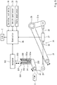
- Fig. 2 is a schematic view of an operation system of a transmission system 20 of the vehicle 1 of Fig. 1 .
- the transmission 2 is rotatable by an operation force generated by the rider's operation of a shift operation lever 21 (shift operation member), as a driving force for a shift operation of the transmission 2, and is rotatable by a driving force generated by a transmission actuator 22 (e.g., electric motor), as the driving force for the shift operation of the transmission 2.
- a shift operation lever 21 shift operation member
- a transmission actuator 22 e.g., electric motor
- the transmission system 20 includes a manual shift driving force transmission mechanism 23 which transmits the operation force generated by the rider's operation of the shift operation lever 21 to the shift drum 11 (see Fig. 1 ) of the transmission 2, and an automatic shift driving force transmission mechanism 24 which transmits the driving force generated by the transmission actuator 22 to the manual shift driving force transmission mechanism 23.
- the manual shift driving force transmission mechanism 23 mechanically connects the shift operation lever 21 to the first end portion of the shift drum 11.
- the shift operation lever 21 is operated by the rider (e.g., the rider's foot) so that the shift operation lever 21 is pivotable around a pivot shaft 25.
- the manual shift driving force transmission mechanism 23 includes a first rod 26, a load sensor 27 (shift operation detector), a second rod 28, a pivot arm 29, and a rotary member 30.
- the first end portion of the first rod 26 is connected to a pivot part 21a integrated with the shift operation lever 21.
- the pivot part 21a is pivoted around the pivot shaft 25.
- the second rod 28 and the first rod 26 are placed on the same straight line.
- the second end portion of the first rod 26 and the first end portion of the second rod 28 are connected to each other via the load sensor 27.
- the second end portion of the second rod 28 is coupled to the first end portion of the pivot arm 29.
- the second end portion of the pivot arm 29 is secured to the rotary member 30.
- the rotary member 30 is mounted on the first end portion of the shift drum 11 (see Fig. 1 ) so that the rotary member 30 is rotatable together with the shift drum 11.
- the automatic shift driving force transmission mechanism 24 includes a one-direction transmission section 31 disposed between the transmission actuator 22 and the rotary member 30.
- the one-direction transmission section 31 is able to transmit the rotational driving force of the transmission actuator 22 to the rotary member 30.
- the one-direction transmission section 31 is configured to prevent transmission of the operation of the manual shift driving force transmission mechanism 23 to the transmission actuator 22, the operation of the manual shift driving force transmission mechanism 23 being caused by the rider's operation of the shift operation lever 21.
- the one-direction transmission section 31 includes an engaged member 32 and an engagement member 33.
- the engaged member 32 includes an engaged part 32a and is operative in response to the operation of the transmission actuator 22.
- the engaged member 32 is a plate-shaped member which is rotated by a rotary shaft 34 actuated by the transmission actuator 22.
- the engaged part 32a is an elongated engaged hole formed in the engaged member 32.
- the engagement member 33 includes an engagement part 33a which is engageable with the engaged part 32a, and is operative in response to the operation of the manual shift driving force transmission mechanism 23 (to be precise, the rotary member 30).
- the engagement member 33 is an arm-shaped member protruding from the rotary member 30.
- the engagement part 33a is an engagement pin to be insertable from the tip end portion of the engagement member 33 into the engaged hole of the engaged part 32a.
- the one-direction transmission section 31 includes an allowance part 35 formed between the engaged part 32a and the engagement part 33a in an operation direction of the engagement member 33 which is operative in response to the operation of the manual shift driving force transmission mechanism 23.
- the allowance part 35 is formed in a region including the entire movement range of the engagement part 33a which is operative in response to the operation of the manual shift driving force transmission mechanism 23.
- the driving force transmitted from the manual shift driving force transmission mechanism 23 is cut off in the allowance part 35, and this driving force is not transmitted to the transmission actuator 22 via the engaged member 32. This makes it possible to prevent a situation in which a mechanical resistance caused by the transmission actuator 22 is transmitted to the rider when the shift operation lever 21 is operated by the rider.
- the engaged member 32 is pivoted until the engaged part 32a contacts the engagement part 33a by the rotation of the rotary shaft 44 caused by the transmission actuator 22. Following this, the engaged member 32 is further pivoted by the transmission actuator 22, and thus the engagement part 33a is pushed by the engaged part 32a. With this operation, the rotary member 30 is rotated and the shift drum 11 is rotated. In this way, automatic shift is performed.
- the transmission actuator 22 may be controlled so that the rotational speed of the rotary shaft 34 is decreased immediately before the engaged part 32a contacts the engagement part 33a.
- the transmission actuator 22 is controlled so that so that the engagement part 33a returns to the center of the hole of the engaged member 32 in the operation direction of the engagement part 33a.
- the transmission system 20 includes a controller 36 (control unit), an engine speed sensor 37, a vehicle speed sensor 38, and an operation input device 39.
- the controller 36 includes a processor, a volatile memory, a non-volatile memory, an I/O interface, or the like.
- the controller 36 is implemented in such a way that the processor performs calculations (computations) by use of the volatile memory based on the program stored in the non-volatile memory.
- the controller 36 is configured to control the engine E and the transmission actuator 22.
- the engine speed sensor 37 is configured to detect the rotational speed of the crankshaft Ea of the engine E.
- the vehicle speed sensor 38 is configured to detect the traveling speed of the vehicle 1.
- the vehicle speed sensor 38 is a sensor which detects the rotational speed of the driven wheel.
- the operation input device 39 is operated by, for example, the rider's hand.
- the operation input device 39 is an input button or an input lever.
- the controller 36 determines that the engine E is being accelerated (the engine speed is being increased) based on the detection signal of the engine speed sensor 37, and the load sensor 27 detects the beginning (initiation) of the shift operation of the transmission 2 which is performed by the rider's operation of the shift operation lever 21, the controller 36 compensates a command value given to the engine E so that the engine speed is decreased. For example, the ignition is temporarily stopped or the throttle opening rate is temporarily reduced.
- the load sensor 27 serves as a shift operation detector which detects the shift operation of the transmission 2 which is performed by the rider's operation of the shift operation lever 21.
- the controller 36 determines that the engine E is being decelerated (the engine speed is being decreased) based on the detection signal of the engine speed sensor 37, and the load sensor 27 detects the beginning of the shift operation of the transmission 2 which is performed by the rider's operation of the shift operation lever 21, the controller 36 compensates a command value given to the engine E so that the engine speed is increased. For example, the throttle opening rate is temporarily increased.
- the operation force generated by the rider's operation of the shift operation lever 21 is transmitted as the shift driving force for the shift operation, to the shift drum 11 of the transmission 2 via the manual shift driving force transmission mechanism 23.
- the rider can receive a reaction force from the transmission 2. Therefore, in the vehicle 1 having the function of the manual shift and the function of the automatic shift, the rider can feel that the rider is performing the operation during the manual shift. This improves the rider's operation feeling.
- the controller 36 When at least one of a case where the shift command is input to the operation input device 39 by the rider and a case where the vehicle speed detected by the vehicle speed sensor 38 meets a predetermined condition, occurs, the controller 36 outputs a shift command to the transmission actuator 22.
- the controller 36 determines that the engine E is being accelerated based on the detection signal of the engine speed sensor 37, and detects that the shift command is output to the transmission actuator 22, the controller 36 compensates the command value given to the engine E so that the engine speed is decreased. For example, the ignition is temporarily stopped or the throttle opening rate is temporarily reduced.
- the controller 36 serves as a shift operation detector which detects the shift operation of the transmission 2 which is performed by the driving force generated by the transmission actuator 22, by detecting the command given to the transmission actuator 22.
- the controller 36 determines that the vehicle 1 is being decelerated based on the detection signal of the engine speed sensor 37 and detects that the shift command is output to the transmission actuator 22, the controller 36 compensates the command value given to the engine E so that the engine speed is increased. For example, the throttle opening rate is temporarily increased.
- the vehicle 1 may be provided with only one of the vehicle speed sensor 38 and the operation input device 39.
- Fig. 3 is a schematic view of the operation system of a transmission system 120 according to Modified Example 1.
- Fig. 4 is a graph showing the spring constant of spring members (buffering members) 141, 142 of Fig. 3 .
- the same constituents as those of Embodiment 1 are designated by the same reference symbols and will not be described in repetition.
- the spring members (buffering members) 141, 142 are disposed in an allowance part 135 of a one-direction transmission section 131 of an automatic shift driving force transmission mechanism 124.
- An engagement member 133 is operative in response to the operation of the manual shift driving force transmission mechanism 23 (specifically, the rotary member 30).
- An engagement part 133a protrudes from the tip end portion of the engagement member 133.
- An engaged member 132 is rotatable by the rotary shaft 34 actuated by the transmission actuator 22.
- An engaged part 32a which is an engaged hole which is elongated in a displacement direction of the engagement part 133a, is formed in the engaged member 132.
- the engagement part 133a also serves as a spring seat supporting the inner ends of the spring members 141, 142.
- the engaged part 132a also serves as a spring seat supporting the outer ends of the spring members 141, 142.
- each of the spring members 141, 142 has a non-linear spring constant which increases when a degree of displacement of the spring member 141, 142, increases due to the displacement of the engagement part 133a.
- the spring members 141, 142 can mitigate an impact generated between the engagement part 133a and the engaged part 132a. This makes it possible to suppress generation of an impact in the transmission actuator 22, in the automatic shift. As a result, the life of the transmission actuator 22 can be extended. Since each of the spring members 141, 142 has the non-linear spring constant, the operation resistance caused by the spring members 141, 142 can be suppressed at the initial stage of the shift operation of the transmission 2 which is performed by the driving force generated by the transmission actuator 22. Thus, the automatic shift can be quickly performed while mitigating an impact generated between the engagement part 133a and the engaged part 132a.
- the other constituents are the same as those of Embodiment 1 and will not be described in repetition.
- Fig. 5 is a schematic view of an operation system of a transmission system 220 according to Modified Example 2.
- spring members (buffering members) 241, 242 are disposed in an allowance part 235 of a one-direction transmission section 231 of an automatic shift driving force transmission mechanism 224.
- An engagement member 233 is operative in response to the operation of the manual shift driving force transmission mechanism 23.
- An engagement part 233a with a cylinder shape protrudes from the tip end portion of the engagement member 233.
- a transmission actuator 222 is a linear motion actuator.
- An engaged member 232 with a rod shape is actuated by the transmission actuator 222.
- An engaged part 232a is formed in the engaged member 232 and is configured to be insertable into the inner space of the engagement part 133a.
- the engaged part 232a actuated by the transmission actuator 222 is configured to reciprocate like a piston, inside the engagement part 233a with the cylinder shape.
- the spring member 242 is disposed between the first end of the engagement part 233a and the engaged part 232a, and the spring member 242 is disposed between the second end of the engagement part 233a and the engaged part 232a.
- the other constituents are the same as those of Embodiment 1 and will not be described in repetition.
- Fig. 6 is a schematic view of the operation system of a transmission system 320 according to Modified Example 3.
- a transmission system 320 flexible members (buffering members) 341, 342, made of, for example, a rubber, are disposed in the allowance part 35 of a one-direction transmission section 331 in an automatic shift driving force transmission mechanism 324.
- the flexible members 341, 342 can mitigate an impact generated between the engagement part 33a and the engaged part 32a.
- the flexible members 341, 342 are disposed with a gap with respect to the engagement part 33a.
- the operation resistance caused by the flexible members 341, 342 does not occur, at the initial stage of the shift operation of the transmission 2 which is performed by the driving force generated by the transmission actuator 22.
- the automatic shift can be quickly performed while mitigating an impact generated between the engagement part 133a and the engaged part 132a.
- the other constituents are the same as those of Embodiment 1 and will not be described in repetition.
- Fig. 7 is a schematic view of an operation system of a transmission system 420 according to Modified Example 4.
- an allowance part 435 is formed in a region of a one-direction transmission section 431, the region partially including a movement range of the engagement part 33a which is operative in response to the operation of the manual shift driving force transmission mechanism 23 so that the region includes a center point of the movement range.
- the allowance part 435 of Fig. 7 is smaller than the allowance part 35 of Fig. 2 , and therefore a distance over which the engagement part 33a moves and contacts the edge of the engaged part 432a in the manual shift is short.
- the controller 436 drives the transmission actuator 22 so that the engagement part 33a does not contact the edge of the engaged part 432a.
- the controller 436 drives the transmission actuator 22 so that the engaged member 432 operates in the movement direction of the engagement part 33a, to be precise, in a direction in which the edge of the engaged part 432a is away from the engagement part 33a which approaches the edge of the engaged part 432a.
- an allowance dimension of the allowance part 435 is set to be small, an impact generated between the engagement part 33a and the engaged part 432a during the shift operation of the transmission 2 which is performed by the driving force generated by the transmission actuator 22 can be reduced. Since the allowance part 435 is formed to include the center point of the movement range of the engagement part 33a, it becomes possible to prevent a situation in which the driving force is transmitted from the manual shift driving force transmission mechanism 23 to the transmission actuator 22 at the initial stage of the shift operation of the transmission 2 which is performed by the rider's operation of the shift operation lever 21.
- the transmission actuator 22 drives the engaged member 432 so that the contact between the engagement part 33a and the engaged part 432a can be avoided. This makes it possible to prevent a situation in which a mechanical resistance is generated by the transmission actuator 22 during the operation of the shift operation lever 21.
- Fig. 8 is a schematic view of a vehicle 501 equipped with (including) a transmission according to Embodiment 2.
- the vehicle 501 is configured to automatically control engagement/disengagement of the main clutch 3.
- a rod 550 connected to the main clutch 3 is inserted into the input shaft 5 of the transmission 2.
- a hydraulic piston device 552 is connected to the end portion of the rod 550, which is on a side opposite to the main clutch 3.
- a hydraulic driving source 553 is connected to the hydraulic piston device 552 and configured to apply a hydraulic pressure (oil pressure) to the hydraulic piston device 552. The hydraulic pressure applied to the hydraulic piston device 552 is adjusted. In this way, the rod 550 reciprocates and the main clutch 3 is engaged or disengaged.
- the hydraulic piston device 552 and the hydraulic driving source 553 constitute a hydraulic actuator 551 (clutch actuator) which actuates the main clutch 3.
- a controller 536 is connected to the hydraulic driving source 553.
- the engine speed sensor 37, the vehicle speed sensor 38, a gear position sensor 540, or the like are connected to the controller 536.
- the above-described transmission system 20 is mounted in the vehicle 501, although not shown in Fig. 8 .
- the controller 536 drives the hydraulic actuator 551 so that the main clutch 3 becomes disengaged, and also drives the hydraulic actuator 551 so that the main clutch 3 becomes gradually engaged with an increase in the vehicle speed.
- the main clutch 3 is partially (half) engaged and the vehicle 501 can start smoothly without a need for the rider to manually operate the main clutch 3 during the starting of the vehicle 501.
- the main clutch 3 may be manually actuated by the rider's manual operation of a clutch lever, in addition to automatic actuation hydraulically performed.
- the clutch actuator is not limited to the hydraulic actuator 551 and may be another actuator (e.g., electric actuator).
- Fig. 9 is a side view showing a first layout example of the transmission actuator 22 in a case where the vehicle 1 is a motorcycle.
- Fig. 10 is a side view showing a second layout example of the transmission actuator 22 in a case where the vehicle 1 is the motorcycle.
- the motorcycle 1 includes a front wheel 601 and a rear wheel 602.
- the front wheel 601 is connected to front forks 603.
- the front forks 603 are supported by a steering shaft (not shown) which is rotatably supported by a head pipe 604.
- a bar-shaped handle 605 which can be gripped by the rider is attached on the steering shaft and extends to the right and the left. When the rider rotates the handle 605 to steer the motorcycle 1, the front wheel 601 is steered.
- a frame 606 extends rearward from the head pipe 604 while being inclined downward.
- the front end portion of a swing arm 607 is supported on the frame 606, and the rear wheel 602 is rotatably supported on the rear end portion of the swing arm 607.
- a fuel tank 608 is disposed rearward of the handle 605.
- a seat 609 which can be straddled by the rider is disposed rearward of the fuel tank 608.
- the transmission 2 is connected to the engine E.
- the driving power output from the output shaft 6 of the transmission 2 is transmitted to the rear wheel 602 via a driving power transmission loop 610 (e.g., a chain or a belt).
- a driving power transmission loop 610 e.g., a chain or a belt
- Steps 611 are provided on right and left sides of the seat 609. The rider's feet rest on the steps 611, respectively.
- the shift operation lever 21 for the manual shift is disposed in front of the step 611.
- the shift operation lever 21 for the automatic shift is disposed above the manual shift driving force transmission mechanism 23 which transmits the operation force of the shift operation lever 21 to the rotary member 30 of the shift drum 11, the shift operation lever 21 for the automatic shift is disposed.
- the transmission actuator 22 may be secured to a crankcase Eb of the engine E, at a location that is in front of the shift operation lever 21.
- the present invention is not limited to the above-described embodiments, and the configuration can be changed, added or deleted, as far as it falls under the scope of protection of the appended claims.
- some of the constituents in one embodiment or modified example may be applied to another embodiment or the like.
- Some of the constituents in one embodiment or modified example may be applied to another embodiment, and may be extracted.
- the above-described transmission system may be applied to a four-wheeled vehicle other than the motorcycle.
- an electric motor may be used instead of the engine E as an internal combustion engine, or the electric motor and the engine may be used.
- the shift operation member is not limited to the lever operated by the rider's foot, and may be operated by the rider's hand.
- the configurations of the engagement part and the engaged part are not limited to the above, and a male-female relation of engagement may be reversed.
Landscapes
- Engineering & Computer Science (AREA)
- General Engineering & Computer Science (AREA)
- Mechanical Engineering (AREA)
- Transportation (AREA)
- Chemical & Material Sciences (AREA)
- Combustion & Propulsion (AREA)
- Automation & Control Theory (AREA)
- Gear-Shifting Mechanisms (AREA)
- Arrangement And Mounting Of Devices That Control Transmission Of Motive Force (AREA)
- Hydraulic Clutches, Magnetic Clutches, Fluid Clutches, And Fluid Joints (AREA)
- Control Of Transmission Device (AREA)
Claims (9)
- Véhicule (1, 501) équipé d'une transmission (2), le véhicule (1, 501) comprenant :une transmission (2) qui modifie une puissance d'entraînement en rotation d'une source de puissance d'entraînement de déplacement (E) ;
un organe d'actionnement de changement de vitesses (21) configuré pour être actionné par un conducteur ;un mécanisme (23) de transmission de force d'entraînement de changement de vitesses manuel qui transmet une force d'actionnement générée par l'actionnement, par le conducteur, de l'organe d'actionnement de changement de vitesses (21), à la transmission (2), comme force d'entraînement de changement de vitesses pour un actionnement de changement de vitesses de la transmission (2) ;un actionneur de transmission (22, 222) qui génère une force d'entraînement ; etun mécanisme (24, 124, 224, 324) de transmission de force d'entraînement de changement de vitesses automatique qui transmet la force d'entraînement générée par l'actionneur de transmission (22, 222) au mécanisme (23) de transmission de force d'entraînement de changement de vitesses manuel, comme force d'entraînement de changement de vitesses,dans lequel le mécanisme (24, 124, 224, 324) de transmission de force d'entraînement de changement de vitesses automatique comporte une section de transmission unidirectionnelle (31, 131, 231, 331, 431) qui empêche la transmission d'un actionnement du mécanisme (23) de transmission de force d'entraînement de changement de vitesses manuel à l'actionneur de transmission (22, 222), l'actionnement du mécanisme (23) de transmission de force d'entraînement de changement de vitesses manuel étant provoqué par l'actionnement, par le conducteur, de l'organe d'actionnement de changement de vitesses (21), la section de transmission unidirectionnelle (31, 131, 231, 331, 431) étant configurée pour transmettre la force d'entraînement générée par l'actionneur de transmission (22, 222) au mécanisme (23) de transmission de force d'entraînement de changement de vitesses manuel,caractérisé en ce que le mécanisme (24, 124, 224, 324) de transmission de force d'entraînement de changement de vitesses automatique comporte :un organe mis en prise (32, 132, 232, 432) qui est actif en réponse à un actionnement de l'actionneur de transmission (22, 222) et est doté d'une partie mise en prise (32a, 132a, 232a, 432a), et un organe d'entrée en prise (33, 133, 233) qui est actif en réponse à l'actionnement du mécanisme (23) de transmission de force d'entraînement de changement de vitesses manuel et est doté d'une partie d'entrée en prise (33a, 133a, 233a) qui peut venir en prise avec la partie mise en prise (32a, 132a, 232a, 432a), eten ce que la section de transmission unidirectionnelle (31, 131, 231, 331, 431) comporte une partie de tolérance (35, 135, 235, 435) formée entre la partie mise en prise (32a, 132a, 232a, 432a) et la partie d'entrée en prise (33a, 133a, 233a), dans une direction d'actionnement de l'organe d'entrée en prise (33, 133, 233) qui est actif en réponse à l'actionnement du mécanisme (23) de transmission de force d'entraînement de changement de vitesses manuel. - Véhicule (1, 501) selon la revendication 1,
dans lequel la section de transmission unidirectionnelle (31, 131, 231, 331, 431) comporte en outre un organe tampon (141, 142, 241, 242, 341, 342) disposé dans la partie de tolérance (35, 135, 235, 435). - Véhicule (1, 501) selon la revendication 2,
dans lequel l'organe tampon (141, 142, 241, 242, 341, 342) présente une constante de ressort non linéaire qui augmente au fur et à mesure qu'un degré de déplacement de l'organe tampon (141, 142, 241, 242, 341, 342) augmente. - Véhicule (1, 501) selon la revendication 2 ou 3,
dans lequel l'organe tampon (141, 142, 241, 242, 341, 342) est disposé avec un espace par rapport à la partie d'entrée en prise (33a, 133a, 233a) dans un état dans lequel l'organe d'actionnement de changement de vitesses (21) est à une position non actionnée et l'actionneur de transmission (22, 222) ne fonctionne pas. - Véhicule (1, 501) selon l'une quelconque des revendications 1 à 4,
dans lequel la partie de tolérance (35, 135, 235, 435) est prévue dans une région comportant une plage de déplacements totale de la partie d'entrée en prise (33a, 133a, 233a) qui est mobile en réponse à l'actionnement du mécanisme (23) de transmission de force d'entraînement de changement de vitesses manuel. - Véhicule (1, 501) selon l'une quelconque des revendications 1 à 4, comprenant en outre :un détecteur d'actionnement de changement de vitesses (27) qui détecte l'actionnement de changement de vitesses de la transmission (2) qui est effectué par l'actionnement, par le conducteur, de l'organe d'actionnement de changement de vitesses (21) ; etune unité de commande (36, 436, 536) qui commande l'actionneur de transmission (22, 222) en réponse à un signal de détection du détecteur d'actionnement de changement de vitesses (27),dans lequel la partie de tolérance (35, 135, 235, 435) est formée dans une région de la section de transmission unidirectionnelle (31, 131, 231, 331, 431), la région comportant partiellement une plage de déplacements de la partie d'entrée en prise (33a, 133a, 233a) qui est mobile en réponse à l'actionnement du mécanisme (23) de transmission de force d'entraînement de changement de vitesses manuel de telle sorte que la région comporte un centre de la plage de déplacements, etdans lequel l'unité de commande (36, 436, 536) entraîne l'actionneur de transmission (22, 222) de telle sorte que l'organe mis en prise (32, 132, 232, 432) fonctionne dans une direction de déplacement de la partie d'entrée en prise (33a, 133a, 233a), dans le cas où le détecteur d'actionnement de changement de vitesses (27) détecte le début d'un actionnement de l'organe d'actionnement de changement de vitesses (21).
- Véhicule (1, 501) selon l'une quelconque des revendications 1 à 5, comprenant en outre :un détecteur d'actionnement de changement de vitesses (27) qui détecte l'actionnement de changement de vitesses de la transmission (2) qui est effectué par l'actionnement, par le conducteur, de l'organe d'actionnement de changement de vitesses (21), et l'actionnement de changement de vitesses de la transmission (2) qui est effectué par la force d'entraînement générée par l'actionneur de transmission (22, 222),une unité de commande (36, 436, 536) qui commande la source de puissance d'entraînement de déplacement (E),dans lequel la transmission (2) est une transmission à embrayage à griffes,dans lequel, dans le cas où la source de puissance d'entraînement de déplacement (E) est accélérée et le détecteur d'actionnement de changement de vitesses (27) détecte le début de l'actionnement de changement de vitesses, l'unité de commande (36, 436, 536) compense une valeur de consigne fournie à la source de puissance d'entraînement de déplacement (E) de telle sorte que la source de puissance d'entraînement de déplacement (E) soit ralentie, etdans lequel, dans le cas où la source de puissance d'entraînement de déplacement (E) est ralentie et le détecteur d'actionnement de changement de vitesses (27) détecte le début de l'actionnement de changement de vitesses, l'unité de commande (36, 436, 536) compense la valeur de consigne fournie à la source de puissance d'entraînement de déplacement (E) de telle sorte que la source de puissance d'entraînement de déplacement (E) soit accélérée.
- Véhicule (501) selon l'une quelconque des revendications 1 à 7, comprenant en outre :un embrayage principal (3) disposé entre la source de puissance d'entraînement de déplacement (E) et la transmission (2) ; etun actionneur d'embrayage (551) qui actionne l'embrayage principal (3).
- Véhicule (501) selon la revendication 8,
dans lequel l'unité de commande (536) entraîne l'actionneur d'embrayage (551) de telle sorte que l'embrayage principal (3) est débrayé pendant que la transmission (2) passe d'un état neutre à un état de transmission de puissance d'entraînement, puis
l'unité de commande (536) entraîne l'actionneur d'embrayage (551) de telle sorte que l'embrayage principal (3) est graduellement embrayé pendant que le véhicule (501) démarre.
Applications Claiming Priority (1)
| Application Number | Priority Date | Filing Date | Title |
|---|---|---|---|
| JP2018066962A JP7032974B2 (ja) | 2018-03-30 | 2018-03-30 | 変速機付き車両 |
Publications (2)
| Publication Number | Publication Date |
|---|---|
| EP3546802A1 EP3546802A1 (fr) | 2019-10-02 |
| EP3546802B1 true EP3546802B1 (fr) | 2020-10-14 |
Family
ID=65138925
Family Applications (1)
| Application Number | Title | Priority Date | Filing Date |
|---|---|---|---|
| EP19152864.5A Active EP3546802B1 (fr) | 2018-03-30 | 2019-01-21 | Véhicule équipé d'une transmission |
Country Status (3)
| Country | Link |
|---|---|
| US (1) | US10711886B2 (fr) |
| EP (1) | EP3546802B1 (fr) |
| JP (1) | JP7032974B2 (fr) |
Families Citing this family (4)
| Publication number | Priority date | Publication date | Assignee | Title |
|---|---|---|---|---|
| JP2022072967A (ja) * | 2020-10-30 | 2022-05-17 | ヤマハ発動機株式会社 | 鞍乗型車両 |
| FR3122631B1 (fr) * | 2021-05-06 | 2023-05-12 | Schorb Innovation Systems | Système de commande de changement de rapport de vitesse pour boîte de vitesse séquentielle, et véhicule équipé d’un tel système |
| WO2023112324A1 (fr) * | 2021-12-17 | 2023-06-22 | ヤマハ発動機株式会社 | Dispositif de commande de changement de rapport |
| JP7426424B2 (ja) | 2022-03-03 | 2024-02-01 | 株式会社トランストロン | シフト操作検出装置、シフトレバー装置および鞍乗型車両 |
Family Cites Families (20)
| Publication number | Priority date | Publication date | Assignee | Title |
|---|---|---|---|---|
| JPH0558191A (ja) * | 1991-09-06 | 1993-03-09 | Ishikawajima Shibaura Mach Co Ltd | 遠隔操縦作業車の変速操作装置 |
| JP3408333B2 (ja) * | 1994-09-22 | 2003-05-19 | 川崎重工業株式会社 | 自動二輪車等のチェンジ装置 |
| JP2001271925A (ja) | 2000-03-28 | 2001-10-05 | Denso Corp | 自動変速機のシフトレンジ切換装置 |
| JP4203363B2 (ja) * | 2003-06-10 | 2008-12-24 | 本田技研工業株式会社 | 車両用の操作装置 |
| JP2005156106A (ja) | 2003-11-28 | 2005-06-16 | Matsushita Electric Ind Co Ltd | 冷蔵庫 |
| JP2006052803A (ja) * | 2004-08-12 | 2006-02-23 | Moric Co Ltd | 電動多段変速機 |
| JP2006064003A (ja) * | 2004-08-24 | 2006-03-09 | Calsonic Kansei Corp | 自動変速機のセレクトアシスト装置 |
| DE102007011359A1 (de) * | 2007-03-07 | 2008-09-11 | Zf Friedrichshafen Ag | Betätigungseinrichtung mit Wählhebelaktuator |
| EP2023019A1 (fr) * | 2007-08-07 | 2009-02-11 | Hoerbiger Antriebstechnik GmbH | Système d'assistance au changement de rapports de transmission |
| DE102007037437A1 (de) * | 2007-08-08 | 2009-02-12 | GM Global Technology Operations, Inc., Detroit | Elektronisches Schaltsystem mit Ausfallsicherung |
| JP2010052726A (ja) | 2008-08-01 | 2010-03-11 | Yamaha Motor Co Ltd | 変速制御システムおよび車両 |
| DE102008042318A1 (de) * | 2008-09-24 | 2010-04-01 | Zf Friedrichshafen Ag | Schaltkraftunterstützung eines schaltbaren Getriebes |
| JP2012237347A (ja) | 2011-05-10 | 2012-12-06 | Honda Motor Co Ltd | エンジンの変速制御装置 |
| JP5722178B2 (ja) * | 2011-09-21 | 2015-05-20 | 本田技研工業株式会社 | 変速制御装置 |
| JP6232915B2 (ja) * | 2013-10-16 | 2017-11-22 | スズキ株式会社 | ハイブリッド二輪車 |
| JP6408882B2 (ja) * | 2014-11-21 | 2018-10-17 | 株式会社ケーヒン | 駆動力制御装置 |
| JP6753209B2 (ja) * | 2016-08-15 | 2020-09-09 | スズキ株式会社 | 車両用変速制御装置 |
| US9890849B1 (en) * | 2016-10-06 | 2018-02-13 | David R. Hall | Electronic shifter with tactile feedback |
| JP7084816B2 (ja) * | 2018-08-06 | 2022-06-15 | カワサキモータース株式会社 | 変速機付き乗物 |
| JP7033031B2 (ja) * | 2018-08-06 | 2022-03-09 | カワサキモータース株式会社 | 変速機付き乗物 |
-
2018
- 2018-03-30 JP JP2018066962A patent/JP7032974B2/ja active Active
- 2018-12-20 US US16/227,346 patent/US10711886B2/en active Active
-
2019
- 2019-01-21 EP EP19152864.5A patent/EP3546802B1/fr active Active
Non-Patent Citations (1)
| Title |
|---|
| None * |
Also Published As
| Publication number | Publication date |
|---|---|
| JP7032974B2 (ja) | 2022-03-09 |
| US20190301602A1 (en) | 2019-10-03 |
| US10711886B2 (en) | 2020-07-14 |
| EP3546802A1 (fr) | 2019-10-02 |
| JP2019178698A (ja) | 2019-10-17 |
Similar Documents
| Publication | Publication Date | Title |
|---|---|---|
| EP3546802B1 (fr) | Véhicule équipé d'une transmission | |
| US8011489B2 (en) | Straddle-type vehicle | |
| EP1808371B1 (fr) | Bateau avec moyens pour contrôler l'opération d'un actionneur de changement de vitesse | |
| JP3840330B2 (ja) | 自動変速機の変速操作入力装置 | |
| JP6156301B2 (ja) | 車両用シフタ装置 | |
| CN109958762B (zh) | 车辆用变速装置 | |
| KR101542440B1 (ko) | 주행식 농작업기 | |
| WO2009110280A1 (fr) | Transplanteur de riz à conducteur porté | |
| KR101391570B1 (ko) | 지게차의 주행조종장치 | |
| US11466771B2 (en) | Transmission-equipped vehicle | |
| JP2006052803A (ja) | 電動多段変速機 | |
| JP5313975B2 (ja) | 切換操作装置 | |
| JP7053174B2 (ja) | 作業車輌 | |
| JP4881269B2 (ja) | 変速装置の非常時切換機構 | |
| JP2022063493A (ja) | ギヤ変速機付き車両の制御装置及び制御方法 | |
| JP6961399B2 (ja) | 作業車輌 | |
| JP6961400B2 (ja) | 作業車輌 | |
| JP2008006980A (ja) | 作業車両 | |
| US7556546B2 (en) | Remote control system for boat | |
| JP6710960B2 (ja) | 作業車両 | |
| JP2022169120A (ja) | 作業車両 | |
| JP2010254157A (ja) | 歩行型管理機 | |
| JP2003170756A (ja) | 変速レバー構造 | |
| JP2007276699A (ja) | シフトレバー装置 | |
| JPH048259B2 (fr) |
Legal Events
| Date | Code | Title | Description |
|---|---|---|---|
| PUAI | Public reference made under article 153(3) epc to a published international application that has entered the european phase |
Free format text: ORIGINAL CODE: 0009012 |
|
| STAA | Information on the status of an ep patent application or granted ep patent |
Free format text: STATUS: REQUEST FOR EXAMINATION WAS MADE |
|
| 17P | Request for examination filed |
Effective date: 20190121 |
|
| AK | Designated contracting states |
Kind code of ref document: A1 Designated state(s): AL AT BE BG CH CY CZ DE DK EE ES FI FR GB GR HR HU IE IS IT LI LT LU LV MC MK MT NL NO PL PT RO RS SE SI SK SM TR |
|
| AX | Request for extension of the european patent |
Extension state: BA ME |
|
| RIC1 | Information provided on ipc code assigned before grant |
Ipc: F16H 63/50 20060101ALI20200312BHEP Ipc: F16H 63/46 20060101ALI20200312BHEP Ipc: F16H 59/02 20060101ALI20200312BHEP Ipc: F16H 61/26 20060101AFI20200312BHEP Ipc: F16H 61/32 20060101ALI20200312BHEP Ipc: F16H 63/16 20060101ALI20200312BHEP |
|
| GRAP | Despatch of communication of intention to grant a patent |
Free format text: ORIGINAL CODE: EPIDOSNIGR1 |
|
| STAA | Information on the status of an ep patent application or granted ep patent |
Free format text: STATUS: GRANT OF PATENT IS INTENDED |
|
| INTG | Intention to grant announced |
Effective date: 20200422 |
|
| GRAS | Grant fee paid |
Free format text: ORIGINAL CODE: EPIDOSNIGR3 |
|
| GRAA | (expected) grant |
Free format text: ORIGINAL CODE: 0009210 |
|
| STAA | Information on the status of an ep patent application or granted ep patent |
Free format text: STATUS: THE PATENT HAS BEEN GRANTED |
|
| AK | Designated contracting states |
Kind code of ref document: B1 Designated state(s): AL AT BE BG CH CY CZ DE DK EE ES FI FR GB GR HR HU IE IS IT LI LT LU LV MC MK MT NL NO PL PT RO RS SE SI SK SM TR |
|
| REG | Reference to a national code |
Ref country code: GB Ref legal event code: FG4D |
|
| REG | Reference to a national code |
Ref country code: AT Ref legal event code: REF Ref document number: 1323909 Country of ref document: AT Kind code of ref document: T Effective date: 20201015 Ref country code: CH Ref legal event code: EP |
|
| REG | Reference to a national code |
Ref country code: DE Ref legal event code: R096 Ref document number: 602019000900 Country of ref document: DE |
|
| REG | Reference to a national code |
Ref country code: IE Ref legal event code: FG4D |
|
| REG | Reference to a national code |
Ref country code: AT Ref legal event code: MK05 Ref document number: 1323909 Country of ref document: AT Kind code of ref document: T Effective date: 20201014 |
|
| REG | Reference to a national code |
Ref country code: NL Ref legal event code: MP Effective date: 20201014 |
|
| PG25 | Lapsed in a contracting state [announced via postgrant information from national office to epo] |
Ref country code: FI Free format text: LAPSE BECAUSE OF FAILURE TO SUBMIT A TRANSLATION OF THE DESCRIPTION OR TO PAY THE FEE WITHIN THE PRESCRIBED TIME-LIMIT Effective date: 20201014 Ref country code: PT Free format text: LAPSE BECAUSE OF FAILURE TO SUBMIT A TRANSLATION OF THE DESCRIPTION OR TO PAY THE FEE WITHIN THE PRESCRIBED TIME-LIMIT Effective date: 20210215 Ref country code: RS Free format text: LAPSE BECAUSE OF FAILURE TO SUBMIT A TRANSLATION OF THE DESCRIPTION OR TO PAY THE FEE WITHIN THE PRESCRIBED TIME-LIMIT Effective date: 20201014 Ref country code: NO Free format text: LAPSE BECAUSE OF FAILURE TO SUBMIT A TRANSLATION OF THE DESCRIPTION OR TO PAY THE FEE WITHIN THE PRESCRIBED TIME-LIMIT Effective date: 20210114 Ref country code: GR Free format text: LAPSE BECAUSE OF FAILURE TO SUBMIT A TRANSLATION OF THE DESCRIPTION OR TO PAY THE FEE WITHIN THE PRESCRIBED TIME-LIMIT Effective date: 20210115 |
|
| REG | Reference to a national code |
Ref country code: LT Ref legal event code: MG4D |
|
| PG25 | Lapsed in a contracting state [announced via postgrant information from national office to epo] |
Ref country code: ES Free format text: LAPSE BECAUSE OF FAILURE TO SUBMIT A TRANSLATION OF THE DESCRIPTION OR TO PAY THE FEE WITHIN THE PRESCRIBED TIME-LIMIT Effective date: 20201014 Ref country code: AT Free format text: LAPSE BECAUSE OF FAILURE TO SUBMIT A TRANSLATION OF THE DESCRIPTION OR TO PAY THE FEE WITHIN THE PRESCRIBED TIME-LIMIT Effective date: 20201014 Ref country code: SE Free format text: LAPSE BECAUSE OF FAILURE TO SUBMIT A TRANSLATION OF THE DESCRIPTION OR TO PAY THE FEE WITHIN THE PRESCRIBED TIME-LIMIT Effective date: 20201014 Ref country code: PL Free format text: LAPSE BECAUSE OF FAILURE TO SUBMIT A TRANSLATION OF THE DESCRIPTION OR TO PAY THE FEE WITHIN THE PRESCRIBED TIME-LIMIT Effective date: 20201014 Ref country code: LV Free format text: LAPSE BECAUSE OF FAILURE TO SUBMIT A TRANSLATION OF THE DESCRIPTION OR TO PAY THE FEE WITHIN THE PRESCRIBED TIME-LIMIT Effective date: 20201014 Ref country code: IS Free format text: LAPSE BECAUSE OF FAILURE TO SUBMIT A TRANSLATION OF THE DESCRIPTION OR TO PAY THE FEE WITHIN THE PRESCRIBED TIME-LIMIT Effective date: 20210214 Ref country code: BG Free format text: LAPSE BECAUSE OF FAILURE TO SUBMIT A TRANSLATION OF THE DESCRIPTION OR TO PAY THE FEE WITHIN THE PRESCRIBED TIME-LIMIT Effective date: 20210114 |
|
| PG25 | Lapsed in a contracting state [announced via postgrant information from national office to epo] |
Ref country code: NL Free format text: LAPSE BECAUSE OF FAILURE TO SUBMIT A TRANSLATION OF THE DESCRIPTION OR TO PAY THE FEE WITHIN THE PRESCRIBED TIME-LIMIT Effective date: 20201014 Ref country code: HR Free format text: LAPSE BECAUSE OF FAILURE TO SUBMIT A TRANSLATION OF THE DESCRIPTION OR TO PAY THE FEE WITHIN THE PRESCRIBED TIME-LIMIT Effective date: 20201014 |
|
| REG | Reference to a national code |
Ref country code: DE Ref legal event code: R097 Ref document number: 602019000900 Country of ref document: DE |
|
| PG25 | Lapsed in a contracting state [announced via postgrant information from national office to epo] |
Ref country code: LT Free format text: LAPSE BECAUSE OF FAILURE TO SUBMIT A TRANSLATION OF THE DESCRIPTION OR TO PAY THE FEE WITHIN THE PRESCRIBED TIME-LIMIT Effective date: 20201014 Ref country code: RO Free format text: LAPSE BECAUSE OF FAILURE TO SUBMIT A TRANSLATION OF THE DESCRIPTION OR TO PAY THE FEE WITHIN THE PRESCRIBED TIME-LIMIT Effective date: 20201014 Ref country code: SM Free format text: LAPSE BECAUSE OF FAILURE TO SUBMIT A TRANSLATION OF THE DESCRIPTION OR TO PAY THE FEE WITHIN THE PRESCRIBED TIME-LIMIT Effective date: 20201014 Ref country code: SK Free format text: LAPSE BECAUSE OF FAILURE TO SUBMIT A TRANSLATION OF THE DESCRIPTION OR TO PAY THE FEE WITHIN THE PRESCRIBED TIME-LIMIT Effective date: 20201014 Ref country code: CZ Free format text: LAPSE BECAUSE OF FAILURE TO SUBMIT A TRANSLATION OF THE DESCRIPTION OR TO PAY THE FEE WITHIN THE PRESCRIBED TIME-LIMIT Effective date: 20201014 Ref country code: EE Free format text: LAPSE BECAUSE OF FAILURE TO SUBMIT A TRANSLATION OF THE DESCRIPTION OR TO PAY THE FEE WITHIN THE PRESCRIBED TIME-LIMIT Effective date: 20201014 |
|
| PLBE | No opposition filed within time limit |
Free format text: ORIGINAL CODE: 0009261 |
|
| STAA | Information on the status of an ep patent application or granted ep patent |
Free format text: STATUS: NO OPPOSITION FILED WITHIN TIME LIMIT |
|
| PG25 | Lapsed in a contracting state [announced via postgrant information from national office to epo] |
Ref country code: MC Free format text: LAPSE BECAUSE OF FAILURE TO SUBMIT A TRANSLATION OF THE DESCRIPTION OR TO PAY THE FEE WITHIN THE PRESCRIBED TIME-LIMIT Effective date: 20201014 Ref country code: DK Free format text: LAPSE BECAUSE OF FAILURE TO SUBMIT A TRANSLATION OF THE DESCRIPTION OR TO PAY THE FEE WITHIN THE PRESCRIBED TIME-LIMIT Effective date: 20201014 |
|
| 26N | No opposition filed |
Effective date: 20210715 |
|
| PG25 | Lapsed in a contracting state [announced via postgrant information from national office to epo] |
Ref country code: LU Free format text: LAPSE BECAUSE OF NON-PAYMENT OF DUE FEES Effective date: 20210121 |
|
| REG | Reference to a national code |
Ref country code: BE Ref legal event code: MM Effective date: 20210131 |
|
| PG25 | Lapsed in a contracting state [announced via postgrant information from national office to epo] |
Ref country code: AL Free format text: LAPSE BECAUSE OF FAILURE TO SUBMIT A TRANSLATION OF THE DESCRIPTION OR TO PAY THE FEE WITHIN THE PRESCRIBED TIME-LIMIT Effective date: 20201014 Ref country code: IT Free format text: LAPSE BECAUSE OF FAILURE TO SUBMIT A TRANSLATION OF THE DESCRIPTION OR TO PAY THE FEE WITHIN THE PRESCRIBED TIME-LIMIT Effective date: 20201014 |
|
| PG25 | Lapsed in a contracting state [announced via postgrant information from national office to epo] |
Ref country code: SI Free format text: LAPSE BECAUSE OF FAILURE TO SUBMIT A TRANSLATION OF THE DESCRIPTION OR TO PAY THE FEE WITHIN THE PRESCRIBED TIME-LIMIT Effective date: 20201014 |
|
| PG25 | Lapsed in a contracting state [announced via postgrant information from national office to epo] |
Ref country code: IE Free format text: LAPSE BECAUSE OF NON-PAYMENT OF DUE FEES Effective date: 20210121 |
|
| PG25 | Lapsed in a contracting state [announced via postgrant information from national office to epo] |
Ref country code: IS Free format text: LAPSE BECAUSE OF FAILURE TO SUBMIT A TRANSLATION OF THE DESCRIPTION OR TO PAY THE FEE WITHIN THE PRESCRIBED TIME-LIMIT Effective date: 20210214 |
|
| REG | Reference to a national code |
Ref country code: DE Ref legal event code: R081 Ref document number: 602019000900 Country of ref document: DE Owner name: KAWASAKI MOTORS, LTD., AKASHI-SHI, JP Free format text: FORMER OWNER: KAWASAKI JUKOGYO KABUSHIKI KAISHA, KOBE-SHI, HYOGO, JP |
|
| PG25 | Lapsed in a contracting state [announced via postgrant information from national office to epo] |
Ref country code: BE Free format text: LAPSE BECAUSE OF NON-PAYMENT OF DUE FEES Effective date: 20210131 |
|
| REG | Reference to a national code |
Ref country code: CH Ref legal event code: PL |
|
| PG25 | Lapsed in a contracting state [announced via postgrant information from national office to epo] |
Ref country code: LI Free format text: LAPSE BECAUSE OF NON-PAYMENT OF DUE FEES Effective date: 20220131 Ref country code: CH Free format text: LAPSE BECAUSE OF NON-PAYMENT OF DUE FEES Effective date: 20220131 |
|
| PGFP | Annual fee paid to national office [announced via postgrant information from national office to epo] |
Ref country code: FR Payment date: 20221208 Year of fee payment: 5 |
|
| PG25 | Lapsed in a contracting state [announced via postgrant information from national office to epo] |
Ref country code: CY Free format text: LAPSE BECAUSE OF FAILURE TO SUBMIT A TRANSLATION OF THE DESCRIPTION OR TO PAY THE FEE WITHIN THE PRESCRIBED TIME-LIMIT Effective date: 20201014 |
|
| PG25 | Lapsed in a contracting state [announced via postgrant information from national office to epo] |
Ref country code: HU Free format text: LAPSE BECAUSE OF FAILURE TO SUBMIT A TRANSLATION OF THE DESCRIPTION OR TO PAY THE FEE WITHIN THE PRESCRIBED TIME-LIMIT; INVALID AB INITIO Effective date: 20190121 |
|
| GBPC | Gb: european patent ceased through non-payment of renewal fee |
Effective date: 20230121 |
|
| PG25 | Lapsed in a contracting state [announced via postgrant information from national office to epo] |
Ref country code: GB Free format text: LAPSE BECAUSE OF NON-PAYMENT OF DUE FEES Effective date: 20230121 |
|
| PG25 | Lapsed in a contracting state [announced via postgrant information from national office to epo] |
Ref country code: MK Free format text: LAPSE BECAUSE OF FAILURE TO SUBMIT A TRANSLATION OF THE DESCRIPTION OR TO PAY THE FEE WITHIN THE PRESCRIBED TIME-LIMIT Effective date: 20201014 |
|
| PG25 | Lapsed in a contracting state [announced via postgrant information from national office to epo] |
Ref country code: TR Free format text: LAPSE BECAUSE OF FAILURE TO SUBMIT A TRANSLATION OF THE DESCRIPTION OR TO PAY THE FEE WITHIN THE PRESCRIBED TIME-LIMIT Effective date: 20201014 |
|
| PG25 | Lapsed in a contracting state [announced via postgrant information from national office to epo] |
Ref country code: MT Free format text: LAPSE BECAUSE OF FAILURE TO SUBMIT A TRANSLATION OF THE DESCRIPTION OR TO PAY THE FEE WITHIN THE PRESCRIBED TIME-LIMIT Effective date: 20201014 |
|
| PG25 | Lapsed in a contracting state [announced via postgrant information from national office to epo] |
Ref country code: FR Free format text: LAPSE BECAUSE OF NON-PAYMENT OF DUE FEES Effective date: 20240131 |
|
| PG25 | Lapsed in a contracting state [announced via postgrant information from national office to epo] |
Ref country code: FR Free format text: LAPSE BECAUSE OF NON-PAYMENT OF DUE FEES Effective date: 20240131 |
|
| PGFP | Annual fee paid to national office [announced via postgrant information from national office to epo] |
Ref country code: DE Payment date: 20251203 Year of fee payment: 8 |