EP3547045B1 - Übertragungsmechanismus einer uhr mit reduziertem kupplungsaufwand - Google Patents
Übertragungsmechanismus einer uhr mit reduziertem kupplungsaufwand Download PDFInfo
- Publication number
- EP3547045B1 EP3547045B1 EP18163966.7A EP18163966A EP3547045B1 EP 3547045 B1 EP3547045 B1 EP 3547045B1 EP 18163966 A EP18163966 A EP 18163966A EP 3547045 B1 EP3547045 B1 EP 3547045B1
- Authority
- EP
- European Patent Office
- Prior art keywords
- wheel set
- transmission mechanism
- wheel
- differential
- frame
- Prior art date
- Legal status (The legal status is an assumption and is not a legal conclusion. Google has not performed a legal analysis and makes no representation as to the accuracy of the status listed.)
- Active
Links
Images


Classifications
-
- G—PHYSICS
- G04—HOROLOGY
- G04F—TIME-INTERVAL MEASURING
- G04F7/00—Apparatus for measuring unknown time intervals by non-electric means
- G04F7/04—Apparatus for measuring unknown time intervals by non-electric means using a mechanical oscillator
- G04F7/08—Watches or clocks with stop devices, e.g. chronograph
- G04F7/0866—Special arrangements
- G04F7/0871—Special arrangements with multiple chronograph functions, i.e. to count multiple running times
-
- G—PHYSICS
- G04—HOROLOGY
- G04B—MECHANICALLY-DRIVEN CLOCKS OR WATCHES; MECHANICAL PARTS OF CLOCKS OR WATCHES IN GENERAL; TIME PIECES USING THE POSITION OF THE SUN, MOON OR STARS
- G04B19/00—Indicating the time by visual means
- G04B19/02—Back-gearing arrangements between gear train and hands
-
- G—PHYSICS
- G04—HOROLOGY
- G04B—MECHANICALLY-DRIVEN CLOCKS OR WATCHES; MECHANICAL PARTS OF CLOCKS OR WATCHES IN GENERAL; TIME PIECES USING THE POSITION OF THE SUN, MOON OR STARS
- G04B13/00—Gearwork
- G04B13/007—Gearwork with differential work
-
- G—PHYSICS
- G04—HOROLOGY
- G04B—MECHANICALLY-DRIVEN CLOCKS OR WATCHES; MECHANICAL PARTS OF CLOCKS OR WATCHES IN GENERAL; TIME PIECES USING THE POSITION OF THE SUN, MOON OR STARS
- G04B13/00—Gearwork
- G04B13/007—Gearwork with differential work
- G04B13/008—Differentials
-
- G—PHYSICS
- G04—HOROLOGY
- G04B—MECHANICALLY-DRIVEN CLOCKS OR WATCHES; MECHANICAL PARTS OF CLOCKS OR WATCHES IN GENERAL; TIME PIECES USING THE POSITION OF THE SUN, MOON OR STARS
- G04B13/00—Gearwork
- G04B13/02—Wheels; Pinions; Spindles; Pivots
-
- G—PHYSICS
- G04—HOROLOGY
- G04B—MECHANICALLY-DRIVEN CLOCKS OR WATCHES; MECHANICAL PARTS OF CLOCKS OR WATCHES IN GENERAL; TIME PIECES USING THE POSITION OF THE SUN, MOON OR STARS
- G04B27/00—Mechanical devices for setting the time indicating means
- G04B27/02—Mechanical devices for setting the time indicating means by making use of the winding means
- G04B27/06—Mechanical devices for setting the time indicating means by making use of the winding means with rocking bar
- G04B27/065—Changing the winding position to the setting position and vice versa is done with an independant part of the winding or setting mechanism
-
- G—PHYSICS
- G04—HOROLOGY
- G04B—MECHANICALLY-DRIVEN CLOCKS OR WATCHES; MECHANICAL PARTS OF CLOCKS OR WATCHES IN GENERAL; TIME PIECES USING THE POSITION OF THE SUN, MOON OR STARS
- G04B3/00—Normal winding of clockworks by hand or mechanically; Winding up several mainsprings or driving weights simultaneously
- G04B3/06—Keys or the like with means preventing overwinding
-
- G—PHYSICS
- G04—HOROLOGY
- G04F—TIME-INTERVAL MEASURING
- G04F7/00—Apparatus for measuring unknown time intervals by non-electric means
- G04F7/04—Apparatus for measuring unknown time intervals by non-electric means using a mechanical oscillator
- G04F7/08—Watches or clocks with stop devices, e.g. chronograph
- G04F7/0842—Watches or clocks with stop devices, e.g. chronograph with start-stop control mechanisms
- G04F7/0861—Watches or clocks with stop devices, e.g. chronograph with start-stop control mechanisms actuated by other than push-buttons, e.g. bezel or lever
Definitions
- the invention relates to a clockwork transmission mechanism, arranged to be integrated into a clockwork movement and comprising at least one differential mechanism comprising at least one mobile satellite mounted loose in pivoting and at least three main mobiles constituting inputs or outputs of said differential mechanism, which three main mobiles consist of a chassis, a first mobile arranged to cooperate with a first gear train, and a second mobile arranged to cooperate with a second gear train, only one of said three main mobiles carrying at at least one said satellite mobile permanently meshing with the two other main mobiles, either directly or through at least one intermediate mobile which permanently meshes with one of said two other main mobiles or which is fixed in rotation to the one of said two other main mobiles, said differential mechanism being capable of kinematically connecting said first mobile and said second moving part in an engagement position, and in disengaging them kinematically in an disengaging position.
- the invention also relates to a timepiece movement comprising at least one such transmission mechanism.
- the invention also relates to a timepiece, in particular a watch, comprising at least one such movement, and/or comprising at least one such transmission mechanism.
- the invention also relates to a timepiece movement comprising at least one such transmission mechanism.
- the invention relates to the field of mechanical clockwork mechanisms.
- the clutch function has often been used: In a winding and time-setting mechanism, for example, the sliding pinion performs this engagement and disengagement function when the crown passes from position T1 (winding) to position T2 (time-setting ), and vice versa when the crown returns from position T2 to position T1.
- the clutch is double, because the winding disengages while the time-setting engages, and vice versa.
- the Start-Stop (or on/off) function is ensured by a clutch (Start) and disengagement (Stop) mechanism.
- the chronograph clutch can be radial by meshing/disengagement of the teeth of the two wheels which are brought together/moved away. It can also be axial, or vertical, when two wheels which pivot coaxially are held in contact by a spring, or held apart by a fork system.
- the document EP3021175A1 on behalf of AUDEMARS PIGUET describes a split-seconds device with an epicyclic train for a timepiece, in particular for a chronograph watch, the device comprising a split-seconds pinion carrying a split-seconds hand and mounted in a freely rotatable manner around an axis of rotation of the timepiece.
- the device comprises a differential comprising an input mobile capable of being kinematically linked to an energy source of the timepiece, a first output mobile kinematically linked to the input mobile by at least one satellite and meshing with the split-seconds gear, a second output wheel set kinematically linked to the input wheel set by said at least one satellite, and a control lever making it possible to lock either the first output wheel set or the second output wheel set, so that the between the first output mobile and the second output mobile which is released by the control lever is capable of being driven by the input mobile when the latter is kinematically linked to the energy source of the timepiece , thus making it possible to block, respectively to release the split-seconds needle.
- the invention proposes to provide an alternative solution to the mechanisms mentioned above, and which limits the number of moving components to perform the clutch and disengage functions.
- the invention relates to a clockwork transmission mechanism according to claim 1.
- the invention also relates to a timepiece movement comprising at least one such transmission mechanism.
- the invention also relates to a timepiece, in particular a watch, comprising at least one such movement, and/or comprising at least one such transmission mechanism.
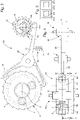
- the invention relates to a clockwork transmission mechanism 100, arranged to be integrated into a clockwork movement 500, and comprising at least one differential mechanism 10.
- This differential mechanism 10 comprises at least one satellite mobile 3, which is mounted for pivoting, and at least three main mobiles constituting inputs or outputs of the differential mechanism 10.
- These three main mobiles are constituted by a frame 60, a first wheel set 1 arranged to cooperate with a first gear train, and a second wheel set 2 arranged to cooperate with a second wheel train. Only one of these three main mobiles carries at least one such satellite mobile 3 permanently meshing with the other two main mobiles, either directly or through at least one intermediate mobile 8 which permanently meshes with the one of the two other main mobiles, or which is integral in rotation with one of the two other main mobiles.
- This differential mechanism 10 is able to kinematically connect the first mobile 1 and the second mobile 2 in an engagement position, and to disengage them kinematically in a disengaged position.
- the transmission mechanism 100 further comprises control means 20, which are arranged to block only one of these three main mobiles, to carry out the clutch of the differential mechanism 10, or to completely release the frame 60 and the first mobile 1 and the second mobile 2 to disengage the differential mechanism 10, according to the position printed on the control means 20 by a selector 30 which comprises the transmission mechanism 100 and which is arranged to cooperate with an actuator which comprises a clock movement 500, and/or to be maneuvered by a user, or even to both cooperate with such an actuator and be maneuverable by a user.
- control means 20 which are arranged to block only one of these three main mobiles, to carry out the clutch of the differential mechanism 10, or to completely release the frame 60 and the first mobile 1 and the second mobile 2 to disengage the differential mechanism 10, according to the position printed on the control means 20 by a selector 30 which comprises the transmission mechanism 100 and which is arranged to cooperate with an actuator which comprises a clock movement 500, and/or to be maneuvered by a user, or even to both cooperate with such an actuator and be maneuverable by a user.
- This blocking wheel is that of the three main wheels on which the differential mechanism 10 is locked in the clutch position, by elastic return means 40, which are arranged to exert on this blocking wheel a meshing torque or friction, the calibration of which allows safety disengagement when the torque transmitted from one to the other of the other main mobiles, which do not constitute this locking mobile, is greater than the meshing or friction torque.
- this selector 30 comprises at least one column wheel 31, which is arranged to, according to its angular position, modify the angular position of a rocker 21 that comprises the control means 20.
- This Rocker 21 includes a first beak 22 which is arranged to immobilize or release, depending on its position, a peripheral toothing that includes the blocking mobile.
- the blocking mobile comprises an external toothing with wolf teeth, so as to allow a safety clutch in one direction of rotation.
- the transmission mechanism 100 further includes mechanical locking means 50, which are arranged to be operated by an actuator that includes a clock movement 500 or/and by a user, and which are arranged to block these means. control 20 in an engaged or disengaged position.
- the frame 60, the first mobile 1, and the second mobile 2 are arranged to pivot around axes parallel to the same differential direction.
- each satellite mobile 3 is arranged to pivot around an axis parallel to this differential direction.
- each satellite mobile 3 is arranged to pivot around an axis perpendicular to the differential direction.
- each mobile satellite 3 is arranged to pivot around an axis which is oblique and not perpendicular with respect to the differential direction.
- this satellite mobile 3 is a satellite pinion.
- the satellite mobile is made up of a pinion and a wheel.
- the locking mobile which is that of said three main mobiles on which the differential mechanism 10 is locked in the clutch position, is the frame 60.
- this frame 60 is a ring gear 6 comprising an external toothing with wolf teeth.
- the at least one satellite mobile 3, or even each satellite mobile 3 is carried by the first mobile 1 or the second mobile 2 and permanently meshes with a toothing 4 of a shaft 5 integral at least in rotation with the second mobile 2 or respectively of the first mobile 1, and the at least one satellite 3, or even each satellite mobile 3, permanently meshes with said ring gear 6.
- this differential mechanism 10 comprises at least one planetary gear, the first wheel set 1 of which constitutes the planet carrier, the second wheel set 2 constitutes the inner sun gear, and the ring gear 6 of which constitutes the outer sun gear and is coaxial with the second wheel set. 2 and to the first mobile 1.
- Each satellite 3 of this planetary gear train is enclosed between the first mobile 1 and the second mobile 2, or between the first mobile 1 and a frame 7 that comprises the transmission mechanism 100, this frame is not not shown so as not to overload the figure. In a particular case, this frame 7 is integral with the second mobile 2.
- a simple differential system is not limiting. Indeed, one can use in a similar way a satellite differential and two crowns, a differential with two sun gears, a spherical differential, or other.
- the use of a ring gear for blocking is not limiting, it may in fact be advantageous, depending on the transmission ratios to be established, to perform the blocking on one or the other input or output of one of these differential gears.
- the principle of the invention can be generalized to a differential mechanism 10 which comprises several stages, and in particular each stage comprising an epicyclic train.
- a double clutch mechanism is commonly used in watchmaking.
- the figures 3 and 4 illustrate such a double clutch, with an additional planetary gear train, a third wheel set 91 of which constitutes the planet carrier, the second wheel set 2 constitutes the inner sun gear, and a ring gear 96 of which constitutes the outer sun gear and is coaxial with the second wheel set 2 and with a third mobile 91, and of which each secondary satellite 93 is enclosed between the third mobile 91 and the frame 7.
- the control means 20 comprise a rocker 21 which comprises a first beak 22 arranged to immobilize or release, depending on its position, a toothing device that includes the mobile blocking, and which includes a second arm 29 having a second beak 28 at its distal end.
- At least one planetary gear train and more particularly each planetary gear train, only comprises gear drive mechanisms.
- At least one planetary gear train and more particularly each planetary gear train, comprises at least one friction drive mechanism.
- the figure 6 illustrates a transmission mechanism 100 which comprises a simple clutch with a spherical differential mechanism 10, and with locking by frame, which comprises such a frame 60 enclosed between a first wheel set 1 and a second wheel set 2, and which carries a guide hub 61 in crazy rotation of each satellite mobile 3 with an axis perpendicular to a differential direction, to which the pivot axes of the three main mobiles are parallel.
- Each satellite mobile 3 permanently meshes with the first mobile 1 and with the second mobile 2.
- the figure 7 illustrates a transmission mechanism 100 comprises a simple clutch with differential mechanism 10 with two solar inputs, and with locking by frame, which comprises such a frame 60 enclosed between a first mobile 1 and a second mobile 2, and which carries a hub 61 of crazy rotation guidance of each satellite mobile 3 with an axis parallel to a differential direction to which the pivot axes of the three main mobiles are parallel.
- Each satellite mobile 3 permanently meshes with an intermediate mobile 8 which permanently meshes with one of the two other main mobiles, or which is integral in rotation with one of the other two main mobiles.
- the differential mechanism 10 comprises at least two inputs or outputs consisting of a first mobile 1 arranged to cooperate with a first gear train and a second mobile 2 arranged to cooperate with a second gear train, the differential mechanism 10 being able to kinematically connect the first mobile 1 and the second mobile 2 in a clutch position, and to disconnect them kinematically in a disengaged position.
- the invention thus comprises a differential gear train, two inputs of which are used to transmit the rotation of the gear train, while the third input is used to engage and disengage the transmission.
- the differential mechanism 10 comprises at least one mobile satellite 3, which is carried by the first mobile 1, and which permanently meshes with a toothing 4 of a shaft 5 secured at least in rotation to the second mobile 2.
- This at least one satellite 3 permanently meshes with a ring gear 6 constituting another input or output of the differential mechanism 10
- the control means 20 are here arranged to block the crown 6, to carry out the clutch of the differential mechanism 10, or to completely release the crown 6, to carry out the disengagement of the differential mechanism 10, according to the position printed on the control means 20 by such a selector 30.
- control is controlled by a selector 30 which comprises at least one column wheel 31 arranged to, according to its angular position, modify the angular position of the rocker 21 which the control means 20 comprise.
- alternative control means can be used, such as a shuttle, rocker, or the like.
- the locking is indirect by elastic return means 40 in the form of a control spring here connected to a frame 7, or to a plate, a bridge or the like, which offers the possibility of a safety clutch if the torque transmitted becomes greater than the passing torque of the teeth of crown 6 on the control.
- the control means 20 are biased towards the crown 6, to achieve the clutch of the differential mechanism 10, by elastic return means 40 arranged to exert on the crown 6 a meshing or friction torque, the calibration of which allows a safety clutch when the torque transmitted from the first mobile 1 to the second mobile 2, or vice versa, is greater than the meshing or friction torque.
- the ring gear 6 comprises an external toothing with wolf teeth so as to allow a safety clutch in one direction of rotation.
- the invention also relates to a timepiece movement 500 comprising at least one such transmission mechanism 100.
- the invention also relates to a timepiece 1000, in particular a watch, comprising at least one such movement 500 and/or comprising at least one such transmission mechanism 100.
- the invention constitutes an alternative solution to the known solutions, and has the advantage of limiting the number of moving components to perform the clutching and disengaging function, in particular in comparison with the clamps of the vertical clutches.
- the invention makes it possible to limit the efforts (forces and/or torques) necessary to ensure engagement and disengagement.
- the invention can be dimensioned to ensure the transmission of a greater torque, in particular in the case of the construction of a vertical chronograph clutch where the torque is ensured by friction.
- the invention allows the construction of simple clutches like the chronograph clutch: On/Off, and double clutches like the winding and time-setting mechanisms: function 1 / function 2.
- the invention also makes it possible to size a torque threshold with safety clutch.
Landscapes
- Physics & Mathematics (AREA)
- General Physics & Mathematics (AREA)
- Measurement Of Unknown Time Intervals (AREA)
- Retarders (AREA)
- Hydraulic Clutches, Magnetic Clutches, Fluid Clutches, And Fluid Joints (AREA)
Claims (20)
- Übertragungsmechanismus (100) für die Uhrmacherei, der angeordnet ist, um in ein Werk für die Uhrmacherei (500) integriert zu werden, und der wenigstens einen Differenzialmechanismus (10) umfasst, der wenigstens einen Satellitendrehteil (3), der frei drehbar montiert ist, und wenigstens drei Hauptdrehteile umfasst, welche Eingänge und Ausgänge des Differenzialmechanismus (10) bilden, wobei die drei Hauptdrehteile von einem Chassis (60) gebildet werden, ein erster Drehteil (1) angeordnet, um mit einem ersten Räderwerk zusammenzuwirken, und ein zweiter Drehteil (2) angeordnet, um mit einem zweiten Räderwerk zusammenzuwirken, wobei ein einziger der drei Hauptdrehteile Träger von wenigstens einem besagten Satellitendrehteil (3) ist, der permanent in die zwei anderen Hauptdrehteile eingreift, entweder direkt oder über wenigstens einen Zwischendrehteil (8), der permanent in einen der zwei anderen Hauptdrehteile eingreift oder der drehfest mit einem der zwei anderen Hauptdrehteile verbunden ist, wobei der Differenzialmechanismus (10) fähig ist, den ersten Drehteil (1) und den zweiten Drehteil (2) in einer Kupplungsposition kinematisch zu verbinden und sie in einer Auskupplungsposition kinematisch zu lösen, wobei der Übertragungsmechanismus (100) noch Steuermittel (20) umfasst, die angeordnet sind, um einen einzigen der drei Hauptdrehteile festzuspannen, um die Kupplung des Differenzialmechanismus (10) auszuführen oder um den Chassis (60) und den ersten Drehteil (1) und den zweiten Drehteil (2) vollständig freizugeben, um die Auskupplung des Differenzialmechanismus (10) auszuführen, je nach Position, die den Steuermitteln (20) durch eine Wahlvorrichtung (30) aufgedruckt wird, welche der Übertragungsmechanismus (100) umfasst und die angeordnet ist, um mit einem Wirkglied zusammenzuwirken, welches ein besagtes Werk für die Uhrmacherei (500) umfasst, oder/und um von einem Benutzer betätigt zu werden, und wobei die Steuermittel (20) zu einem Festspanndrehteil zurückgezogen werden, der jener der drei Hauptdrehteile ist, an dem das Festspannen des Differenzialmechanismus (10) in Kupplungsposition erfolgt, durch elastische Rückzugmittel (40), die angeordnet sind, um auf den Festspanndrehteil ein Eingriffs- oder Reibungsdrehmoment auszuüben, dessen Regulierung eine Sicherheitsauskupplung zulässt, wenn das von einem auf den anderen der verschiedenen anderen Hauptdrehteile des Festspanndrehteils übertragene Drehmoment grösser als das Eingriffs- oder Reibungsdrehmoment ist, dadurch gekennzeichnet, dass der Festspanndrehteil eine äußere Zahnung mit Kerbverzahnung umfasst, um eine Sicherheitsauskupplung in einem Drehsinn zu ermöglichen.
- Übertragungsmechanismus (100) nach Anspruch 1, dadurch gekennzeichnet, dass die Wahlvorrichtung (30) wenigstens ein Säulenrad (31) umfasst, das angeordnet ist, um, je nach seiner Winkelposition, die Winkelposition einer Wippe (21) zu ändern, welche die Steuermittel (20) umfassen, wobei die Wippe (21) einen ersten Schnabel (22) umfasst, der angeordnet ist, um, je nach seiner Position, eine periphere Zahnung, welche der Festspanndrehteil umfasst, anzuhalten oder freizugeben.
- Übertragungsmechanismus (100) nach Anspruch 1 oder 2, dadurch gekennzeichnet, dass der Übertragungsmechanismus (100) noch mechanische Verriegelungsmittel (50) umfasst, die angeordnet sind, um von einem Wirkglied betätigt zu werden, welches ein besagtes Werk für die Uhrmacherei (500) umfasst, oder/und von einem Benutzer, und die angeordnet sind, um die Steuermittel (20) in einer eingekuppelten oder ausgekuppelten Position festzuspannen.
- Übertragungsmechanismus (100) nach einem der Ansprüche 1 bis 3, dadurch gekennzeichnet, dass der Chassis (60), der erste Drehteil (1) und der zweite Drehteil (2) angeordnet sind, um sich um Achsen zu drehen, die parallel zu einer gleichen Differenzialrichtung verlaufen.
- Übertragungsmechanismus (100) nach Anspruch 4, dadurch gekennzeichnet, dass jeder besagte Satellitendrehteil (3) angeordnet ist, um sich um eine Achse zu drehen, die parallel zur Differenzialrichtung verläuft.
- Übertragungsmechanismus (100) nach Anspruch 4, dadurch gekennzeichnet, dass jeder besagte Satellitendrehteil (3) angeordnet ist, um sich um eine Achse zu drehen, die senkrecht zur Differenzialrichtung verläuft.
- Übertragungsmechanismus (100) nach Anspruch 4, dadurch gekennzeichnet, dass jeder besagte Satellitendrehteil (3) angeordnet ist, um sich um eine Achse zu drehen, die schief und nicht senkrecht in Bezug auf die Differenzialrichtung verläuft.
- Übertragungsmechanismus (100) nach einem der Ansprüche 1 bis 7, dadurch gekennzeichnet, dass der Festspanndrehteil, der jener der drei Hauptdrehteile ist, an dem das Festspannen des Differenzialmechanismus (10) in Kupplungsposition erfolgt, der Chassis (60) ist.
- Übertragungsmechanismus (100) nach einem der Ansprüche 1 bis 8, dadurch gekennzeichnet, dass der Chassis (60) eine Krone (6) ist.
- Übertragungsmechanismus (100) nach Anspruch 9, dadurch gekennzeichnet, dass der wenigstens eine Satellitendrehteil (3) von dem ersten Drehteil (1) oder dem zweiten Drehteil (2) getragen wird und permanent in eine Zahnung (4) einer Welle (5) eingreift, die wenigstens drehfest mit dem zweiten Drehteil (2) oder beziehungsweise dem ersten Drehteil (1) verbunden ist, wobei der wenigstens eine Satellit (3) permanent in die Krone (6) eingreift.
- Übertragungsmechanismus (100) nach Anspruch 10, dadurch gekennzeichnet, dass der Differenzialmechanismus (10) wenigstens einen epizykloiden Zug umfasst, dessen erster Drehteil (1) den Satellitenträger bildet, zweiter Drehteil (2) den Innenplaneten bildet und dessen Krone (6) den Außenplaneten bildet und koaxial mit dem zweiten Drehteil (2) und dem ersten Drehteil (1) ist, und von dem jeder besagte Satellit (3) zwischen dem ersten Drehteil (1) und dem zweiten Drehteil (2) oder zwischen dem ersten Drehteil (1) und einem Gestell (7) eingeschlossen ist, welches der Übertragungsmechanismus (100) umfasst.
- Übertragungsmechanismus (100) nach Anspruch 11, dadurch gekennzeichnet, dass das Gestell (7) fest mit dem zweiten Drehteil (2) verbunden ist.
- Übertragungsmechanismus (100) nach Anspruch 11 oder 12, dadurch gekennzeichnet, dass der Differenzialmechanismus (10) eine Doppelkupplung umfasst, mit einem zusätzlichen epizykloiden Zug, von dem ein dritter Drehteil (91) den Satellitenträger bildet, der zweite Drehteil (2) den Innenplaneten bildet und von dem eine Krone (96) den Außenplaneten bildet und koaxial mit dem ersten Drehteil (2) und einem dritten Drehteil (91) ist, und von dem jeder Nebensatellit (93) zwischen dem dritten Drehteil (91) und dem Gestell (7) eingeschlossen ist, und dadurch, dass die Steuermittel (20) eine Wippe (21) umfassen, die einen ersten Schnabel (22) umfasst, der angeordnet ist, um, je nach seiner Position, eine periphere Zahnung, welche der Festspanndrehteil umfasst, anzuhalten oder freizugeben, und die einen zweiten Arm (29) umfasst, der einen zweiten Schnabel (28) an seinem distalen Ende umfasst.
- Übertragungsmechanismus (100) nach einem der Ansprüche 11 bis 13, dadurch gekennzeichnet, dass jeder besagte epizykloide Zug ausschließlich Antriebsmechanismen mittels Getriebe umfasst.
- Übertragungsmechanismus (100) nach einem der Ansprüche 11 bis 13, dadurch gekennzeichnet, dass wenigstens ein besagter epizykloider Zug wenigstens einen Antriebsmechanismus mittels Reibung umfasst.
- Übertragungsmechanismus (100) nach einem der Ansprüche 1 bis 15, dadurch gekennzeichnet, dass der Differenzialmechanismus (10) mehrere Stufen umfasst, die jeweils einen epizykloiden Zug umfassen.
- Übertragungsmechanismus (100) nach einem der Ansprüche 1 bis 8, dadurch gekennzeichnet, dass der Übertragungsmechanismus (100) eine Einfachkupplung mit sphärischem Differenzialmechanismus (10) und mit Festspannen mittels Chassis umfasst, die einen besagten Chassis (60) umfasst, der zwischen einem besagten ersten Drehteil (1) und einem besagten zweiten Drehteil (2) eingeschlossen ist, und die eine Nabe (61) zur freibeweglichen Drehführung jedes besagten Satellitendrehteils (3) mit einer Achse trägt, die senkrecht zu einer Differenzialrichtung verläuft, zu der die Drehachsen der drei Hauptdrehteile parallel verlaufen, wobei jeder besagte Satellitendrehteil (3) permanent in den ersten Drehteil (1) und in den zweiten Drehteil (2) eingreift.
- Übertragungsmechanismus (100) nach einem der Ansprüche 1 bis 8, dadurch gekennzeichnet, dass der Übertragungsmechanismus (100) eine Einfachkupplung mit Differenzialmechanismus (10) mit zwei Sonneneingängen und mit Festspannen mittels Chassis umfasst, die einen besagten Chassis (60) umfasst, der zwischen einem besagten ersten Drehteil (1) und einem besagten zweiten Drehteil (2) eingeschlossen ist, und die eine Nabe (61) zur freibeweglichen Drehführung jedes besagten Satellitendrehteils (3) mit einer Achse trägt, die parallel zu einer Differenzialrichtung verläuft, zu der die Drehachsen der drei Hauptdrehteile parallel verlaufen, wobei jeder besagte Satellitendrehteil (3) permanent in einen besagten Zwischendrehteil (8) eingreift, der permanent in einen der zwei anderen Hauptdrehteile eingreift oder der drehfest mit einem der zwei anderen Hauptdrehteile verbunden ist.
- Werk für die Uhrmacherei (500), umfassend wenigstens einen Übertragungsmechanismus (100) nach einem der Ansprüche 1 bis 18.
- Teil für die Uhrmacherei (1000), umfassend wenigstens ein Werk (500) nach Anspruch 19 und/oder umfassend wenigstens einen Übertragungsmechanismus (100) nach einem der Ansprüche 1 bis 18.
Priority Applications (4)
| Application Number | Priority Date | Filing Date | Title |
|---|---|---|---|
| EP18163966.7A EP3547045B1 (de) | 2018-03-26 | 2018-03-26 | Übertragungsmechanismus einer uhr mit reduziertem kupplungsaufwand |
| JP2019045588A JP6806828B2 (ja) | 2018-03-26 | 2019-03-13 | 連結力を低減した計時器伝動機構 |
| US16/360,498 US11415942B2 (en) | 2018-03-26 | 2019-03-21 | Timepiece transmission mechanism with reduced coupling force |
| CN201910227997.7A CN110361954B (zh) | 2018-03-26 | 2019-03-25 | 具有降低的联接力的钟表传动机构 |
Applications Claiming Priority (1)
| Application Number | Priority Date | Filing Date | Title |
|---|---|---|---|
| EP18163966.7A EP3547045B1 (de) | 2018-03-26 | 2018-03-26 | Übertragungsmechanismus einer uhr mit reduziertem kupplungsaufwand |
Publications (2)
| Publication Number | Publication Date |
|---|---|
| EP3547045A1 EP3547045A1 (de) | 2019-10-02 |
| EP3547045B1 true EP3547045B1 (de) | 2022-05-04 |
Family
ID=61800387
Family Applications (1)
| Application Number | Title | Priority Date | Filing Date |
|---|---|---|---|
| EP18163966.7A Active EP3547045B1 (de) | 2018-03-26 | 2018-03-26 | Übertragungsmechanismus einer uhr mit reduziertem kupplungsaufwand |
Country Status (4)
| Country | Link |
|---|---|
| US (1) | US11415942B2 (de) |
| EP (1) | EP3547045B1 (de) |
| JP (1) | JP6806828B2 (de) |
| CN (1) | CN110361954B (de) |
Families Citing this family (1)
| Publication number | Priority date | Publication date | Assignee | Title |
|---|---|---|---|---|
| EP4180880A1 (de) | 2021-11-10 | 2023-05-17 | Montres Breguet S.A. | Vorrichtung zur anzeige einer abfolge von angaben einer zeitlichen grösse für eine uhr |
Family Cites Families (13)
| Publication number | Priority date | Publication date | Assignee | Title |
|---|---|---|---|---|
| CH216001A (fr) * | 1939-08-22 | 1941-07-31 | Sonceboz Sa | Pièce d'horlogerie à chronographe. |
| ATE316663T1 (de) * | 2002-10-07 | 2006-02-15 | Vaucher Mft Fleurier Sa | Chronographenuhrwerk |
| EP1708051A1 (de) * | 2005-03-31 | 2006-10-04 | Zenith International SA | Uhr mit einem Wecker |
| EP1944662A1 (de) * | 2007-01-15 | 2008-07-16 | Vaucher Manufacture Fleurier SA | Stundenschlagwerk |
| EP2015145B1 (de) * | 2007-06-11 | 2013-05-01 | Chopard Manufacture SA | Vertikale Kupplungsvorrichtung für Uhr |
| CH702924B1 (fr) * | 2010-06-03 | 2011-10-14 | Patek Philippe Sa Geneve | Mobile à embrayage unidirectionnel, mécanisme de remontage et pièce d'horlogerie comportant ledit mobile. |
| CH703247B1 (fr) * | 2010-06-04 | 2014-12-15 | Milus Internat Sa | Indicateur acoustique de la réserve de marche d'une pièce d'horlogerie. |
| EP2410388B1 (de) * | 2010-07-21 | 2018-04-18 | Blancpain S.A. | Uhr mit Doppelanzeige |
| CN103842916B (zh) * | 2011-09-01 | 2017-06-16 | 劳力士有限公司 | 能够显示两个时区的计时器 |
| EP2615506B1 (de) * | 2012-01-10 | 2014-06-25 | Montres Breguet SA | Vorrichtung zur Schnellkorrektur eines Anzeigesystems |
| JP6262364B2 (ja) * | 2014-03-26 | 2018-01-17 | ザ・スウォッチ・グループ・マネージメント・サービシイズ・エイ ジー | 計時器用制御システム |
| EP3018535B1 (de) * | 2014-11-07 | 2018-09-05 | Montres Breguet SA | Aufziehvorrichtung mit unidirektionaler Antriebsanordnung |
| CH710362A1 (fr) | 2014-11-13 | 2016-05-13 | Société Anonyme De La Mft D'horlogerie Audemars Piguet & Cie | Dispositif de rattrapante à train épicycloïdale pour pièce d'horlogerie. |
-
2018
- 2018-03-26 EP EP18163966.7A patent/EP3547045B1/de active Active
-
2019
- 2019-03-13 JP JP2019045588A patent/JP6806828B2/ja active Active
- 2019-03-21 US US16/360,498 patent/US11415942B2/en active Active
- 2019-03-25 CN CN201910227997.7A patent/CN110361954B/zh active Active
Also Published As
| Publication number | Publication date |
|---|---|
| US20190294110A1 (en) | 2019-09-26 |
| JP2019174457A (ja) | 2019-10-10 |
| CN110361954B (zh) | 2021-05-04 |
| CN110361954A (zh) | 2019-10-22 |
| EP3547045A1 (de) | 2019-10-02 |
| US11415942B2 (en) | 2022-08-16 |
| JP6806828B2 (ja) | 2021-01-06 |
Similar Documents
| Publication | Publication Date | Title |
|---|---|---|
| EP1970778B1 (de) | Uhr mit Anzeige der Gangreserve | |
| EP2945026B1 (de) | Schnellkorrekturmechanismus für Uhr | |
| EP2871534B1 (de) | Triebfeder einer Uhrwerk mit unidirektionalen Zahnraden | |
| EP3499319A2 (de) | Kupplungswippe und kupplungsvorrichtung für uhrmechanismus | |
| EP4058853B1 (de) | Unidirektionale kupplungsfeder, insbesondere für uhrwerk | |
| EP1978419B1 (de) | Aufzugsvorrichtung mit unidirektionale Kupplung | |
| CH714836A2 (fr) | Mécanisme de transmission d'horlogerie avec fonction d'embrayage et de débrayage. | |
| EP2226687B1 (de) | Auskupplungsvorrichtung für Uhrwerksmechanismus und diese Vorrichtung umfassendes Uhrwerk | |
| EP3547045A1 (de) | Übertragungsmechanismus einer uhr mit reduziertem kupplungsaufwand | |
| CH713702B1 (fr) | Mécanisme de compensation de couple, mécanisme à force constante, mouvement de pièce d'horlogerie et pièce d'horlogerie. | |
| EP3944026B1 (de) | Uhrwerkmechanismus mit zählkette | |
| EP3376308B1 (de) | Aufziehmechanismus einer uhr | |
| EP4375759A1 (de) | Kupplungsvorrichtung für uhr | |
| EP2765079B1 (de) | Kabinensitz für Flugzeug | |
| EP3376309B1 (de) | Aufziehmechanismus einer uhr | |
| CH719259A2 (fr) | Système de remontage automatique pour mouvement d'horlogerie. | |
| EP4296788B1 (de) | Vorrichtung zum automatischen aufziehen einer feder im federhaus eines uhrwerks | |
| FR2830299A1 (fr) | Boite de vitesses pour vehicule automobile | |
| EP3855254A1 (de) | Uhrwerk | |
| EP3361323A1 (de) | System zum aufziehen einer uhr | |
| EP1995649B1 (de) | Kugeldifferential, insbesondere für Gangreserveanzeige eines mechanischen Uhrwerks | |
| HK40014864A (en) | Timepiece transmission mechanism with reduced coupling force | |
| EP3232275B1 (de) | Aufziehmechanismus für eine uhr, der mindestens zwei federhäuser umfasst, und uhr, die einen solchen mechanismus umfasst | |
| FR2918434A1 (fr) | Dispositif de commande interne de boite de vitesses | |
| EP0511039A1 (de) | Schaltvorrichtung für Wechselgetriebe mit Planetenradsatz, Drehmomentwandler und Zusatzumkehrstufe |
Legal Events
| Date | Code | Title | Description |
|---|---|---|---|
| PUAI | Public reference made under article 153(3) epc to a published international application that has entered the european phase |
Free format text: ORIGINAL CODE: 0009012 |
|
| STAA | Information on the status of an ep patent application or granted ep patent |
Free format text: STATUS: THE APPLICATION HAS BEEN PUBLISHED |
|
| AK | Designated contracting states |
Kind code of ref document: A1 Designated state(s): AL AT BE BG CH CY CZ DE DK EE ES FI FR GB GR HR HU IE IS IT LI LT LU LV MC MK MT NL NO PL PT RO RS SE SI SK SM TR |
|
| AX | Request for extension of the european patent |
Extension state: BA ME |
|
| STAA | Information on the status of an ep patent application or granted ep patent |
Free format text: STATUS: REQUEST FOR EXAMINATION WAS MADE |
|
| 17P | Request for examination filed |
Effective date: 20200402 |
|
| RBV | Designated contracting states (corrected) |
Designated state(s): AL AT BE BG CH CY CZ DE DK EE ES FI FR GB GR HR HU IE IS IT LI LT LU LV MC MK MT NL NO PL PT RO RS SE SI SK SM TR |
|
| GRAP | Despatch of communication of intention to grant a patent |
Free format text: ORIGINAL CODE: EPIDOSNIGR1 |
|
| STAA | Information on the status of an ep patent application or granted ep patent |
Free format text: STATUS: GRANT OF PATENT IS INTENDED |
|
| INTG | Intention to grant announced |
Effective date: 20211119 |
|
| GRAS | Grant fee paid |
Free format text: ORIGINAL CODE: EPIDOSNIGR3 |
|
| GRAA | (expected) grant |
Free format text: ORIGINAL CODE: 0009210 |
|
| STAA | Information on the status of an ep patent application or granted ep patent |
Free format text: STATUS: THE PATENT HAS BEEN GRANTED |
|
| AK | Designated contracting states |
Kind code of ref document: B1 Designated state(s): AL AT BE BG CH CY CZ DE DK EE ES FI FR GB GR HR HU IE IS IT LI LT LU LV MC MK MT NL NO PL PT RO RS SE SI SK SM TR |
|
| REG | Reference to a national code |
Ref country code: GB Ref legal event code: FG4D Free format text: NOT ENGLISH |
|
| REG | Reference to a national code |
Ref country code: CH Ref legal event code: EP |
|
| REG | Reference to a national code |
Ref country code: AT Ref legal event code: REF Ref document number: 1489726 Country of ref document: AT Kind code of ref document: T Effective date: 20220515 |
|
| REG | Reference to a national code |
Ref country code: IE Ref legal event code: FG4D Free format text: LANGUAGE OF EP DOCUMENT: FRENCH Ref country code: DE Ref legal event code: R096 Ref document number: 602018034779 Country of ref document: DE |
|
| REG | Reference to a national code |
Ref country code: LT Ref legal event code: MG9D |
|
| REG | Reference to a national code |
Ref country code: NL Ref legal event code: MP Effective date: 20220504 |
|
| REG | Reference to a national code |
Ref country code: AT Ref legal event code: MK05 Ref document number: 1489726 Country of ref document: AT Kind code of ref document: T Effective date: 20220504 |
|
| PG25 | Lapsed in a contracting state [announced via postgrant information from national office to epo] |
Ref country code: SE Free format text: LAPSE BECAUSE OF FAILURE TO SUBMIT A TRANSLATION OF THE DESCRIPTION OR TO PAY THE FEE WITHIN THE PRESCRIBED TIME-LIMIT Effective date: 20220504 Ref country code: PT Free format text: LAPSE BECAUSE OF FAILURE TO SUBMIT A TRANSLATION OF THE DESCRIPTION OR TO PAY THE FEE WITHIN THE PRESCRIBED TIME-LIMIT Effective date: 20220905 Ref country code: NO Free format text: LAPSE BECAUSE OF FAILURE TO SUBMIT A TRANSLATION OF THE DESCRIPTION OR TO PAY THE FEE WITHIN THE PRESCRIBED TIME-LIMIT Effective date: 20220804 Ref country code: NL Free format text: LAPSE BECAUSE OF FAILURE TO SUBMIT A TRANSLATION OF THE DESCRIPTION OR TO PAY THE FEE WITHIN THE PRESCRIBED TIME-LIMIT Effective date: 20220504 Ref country code: LT Free format text: LAPSE BECAUSE OF FAILURE TO SUBMIT A TRANSLATION OF THE DESCRIPTION OR TO PAY THE FEE WITHIN THE PRESCRIBED TIME-LIMIT Effective date: 20220504 Ref country code: HR Free format text: LAPSE BECAUSE OF FAILURE TO SUBMIT A TRANSLATION OF THE DESCRIPTION OR TO PAY THE FEE WITHIN THE PRESCRIBED TIME-LIMIT Effective date: 20220504 Ref country code: GR Free format text: LAPSE BECAUSE OF FAILURE TO SUBMIT A TRANSLATION OF THE DESCRIPTION OR TO PAY THE FEE WITHIN THE PRESCRIBED TIME-LIMIT Effective date: 20220805 Ref country code: FI Free format text: LAPSE BECAUSE OF FAILURE TO SUBMIT A TRANSLATION OF THE DESCRIPTION OR TO PAY THE FEE WITHIN THE PRESCRIBED TIME-LIMIT Effective date: 20220504 Ref country code: ES Free format text: LAPSE BECAUSE OF FAILURE TO SUBMIT A TRANSLATION OF THE DESCRIPTION OR TO PAY THE FEE WITHIN THE PRESCRIBED TIME-LIMIT Effective date: 20220504 Ref country code: BG Free format text: LAPSE BECAUSE OF FAILURE TO SUBMIT A TRANSLATION OF THE DESCRIPTION OR TO PAY THE FEE WITHIN THE PRESCRIBED TIME-LIMIT Effective date: 20220804 Ref country code: AT Free format text: LAPSE BECAUSE OF FAILURE TO SUBMIT A TRANSLATION OF THE DESCRIPTION OR TO PAY THE FEE WITHIN THE PRESCRIBED TIME-LIMIT Effective date: 20220504 |
|
| PG25 | Lapsed in a contracting state [announced via postgrant information from national office to epo] |
Ref country code: RS Free format text: LAPSE BECAUSE OF FAILURE TO SUBMIT A TRANSLATION OF THE DESCRIPTION OR TO PAY THE FEE WITHIN THE PRESCRIBED TIME-LIMIT Effective date: 20220504 Ref country code: PL Free format text: LAPSE BECAUSE OF FAILURE TO SUBMIT A TRANSLATION OF THE DESCRIPTION OR TO PAY THE FEE WITHIN THE PRESCRIBED TIME-LIMIT Effective date: 20220504 Ref country code: LV Free format text: LAPSE BECAUSE OF FAILURE TO SUBMIT A TRANSLATION OF THE DESCRIPTION OR TO PAY THE FEE WITHIN THE PRESCRIBED TIME-LIMIT Effective date: 20220504 Ref country code: IS Free format text: LAPSE BECAUSE OF FAILURE TO SUBMIT A TRANSLATION OF THE DESCRIPTION OR TO PAY THE FEE WITHIN THE PRESCRIBED TIME-LIMIT Effective date: 20220904 |
|
| PG25 | Lapsed in a contracting state [announced via postgrant information from national office to epo] |
Ref country code: SM Free format text: LAPSE BECAUSE OF FAILURE TO SUBMIT A TRANSLATION OF THE DESCRIPTION OR TO PAY THE FEE WITHIN THE PRESCRIBED TIME-LIMIT Effective date: 20220504 Ref country code: SK Free format text: LAPSE BECAUSE OF FAILURE TO SUBMIT A TRANSLATION OF THE DESCRIPTION OR TO PAY THE FEE WITHIN THE PRESCRIBED TIME-LIMIT Effective date: 20220504 Ref country code: RO Free format text: LAPSE BECAUSE OF FAILURE TO SUBMIT A TRANSLATION OF THE DESCRIPTION OR TO PAY THE FEE WITHIN THE PRESCRIBED TIME-LIMIT Effective date: 20220504 Ref country code: EE Free format text: LAPSE BECAUSE OF FAILURE TO SUBMIT A TRANSLATION OF THE DESCRIPTION OR TO PAY THE FEE WITHIN THE PRESCRIBED TIME-LIMIT Effective date: 20220504 Ref country code: DK Free format text: LAPSE BECAUSE OF FAILURE TO SUBMIT A TRANSLATION OF THE DESCRIPTION OR TO PAY THE FEE WITHIN THE PRESCRIBED TIME-LIMIT Effective date: 20220504 Ref country code: CZ Free format text: LAPSE BECAUSE OF FAILURE TO SUBMIT A TRANSLATION OF THE DESCRIPTION OR TO PAY THE FEE WITHIN THE PRESCRIBED TIME-LIMIT Effective date: 20220504 |
|
| REG | Reference to a national code |
Ref country code: DE Ref legal event code: R097 Ref document number: 602018034779 Country of ref document: DE |
|
| PLBE | No opposition filed within time limit |
Free format text: ORIGINAL CODE: 0009261 |
|
| STAA | Information on the status of an ep patent application or granted ep patent |
Free format text: STATUS: NO OPPOSITION FILED WITHIN TIME LIMIT |
|
| PG25 | Lapsed in a contracting state [announced via postgrant information from national office to epo] |
Ref country code: AL Free format text: LAPSE BECAUSE OF FAILURE TO SUBMIT A TRANSLATION OF THE DESCRIPTION OR TO PAY THE FEE WITHIN THE PRESCRIBED TIME-LIMIT Effective date: 20220504 |
|
| 26N | No opposition filed |
Effective date: 20230207 |
|
| PG25 | Lapsed in a contracting state [announced via postgrant information from national office to epo] |
Ref country code: SI Free format text: LAPSE BECAUSE OF FAILURE TO SUBMIT A TRANSLATION OF THE DESCRIPTION OR TO PAY THE FEE WITHIN THE PRESCRIBED TIME-LIMIT Effective date: 20220504 |
|
| P01 | Opt-out of the competence of the unified patent court (upc) registered |
Effective date: 20230611 |
|
| PG25 | Lapsed in a contracting state [announced via postgrant information from national office to epo] |
Ref country code: MC Free format text: LAPSE BECAUSE OF FAILURE TO SUBMIT A TRANSLATION OF THE DESCRIPTION OR TO PAY THE FEE WITHIN THE PRESCRIBED TIME-LIMIT Effective date: 20220504 |
|
| REG | Reference to a national code |
Ref country code: BE Ref legal event code: MM Effective date: 20230331 |
|
| PG25 | Lapsed in a contracting state [announced via postgrant information from national office to epo] |
Ref country code: LU Free format text: LAPSE BECAUSE OF NON-PAYMENT OF DUE FEES Effective date: 20230326 |
|
| REG | Reference to a national code |
Ref country code: IE Ref legal event code: MM4A |
|
| PG25 | Lapsed in a contracting state [announced via postgrant information from national office to epo] |
Ref country code: IT Free format text: LAPSE BECAUSE OF FAILURE TO SUBMIT A TRANSLATION OF THE DESCRIPTION OR TO PAY THE FEE WITHIN THE PRESCRIBED TIME-LIMIT Effective date: 20220504 Ref country code: IE Free format text: LAPSE BECAUSE OF NON-PAYMENT OF DUE FEES Effective date: 20230326 |
|
| PG25 | Lapsed in a contracting state [announced via postgrant information from national office to epo] |
Ref country code: BE Free format text: LAPSE BECAUSE OF NON-PAYMENT OF DUE FEES Effective date: 20230331 |
|
| PG25 | Lapsed in a contracting state [announced via postgrant information from national office to epo] |
Ref country code: BG Free format text: LAPSE BECAUSE OF FAILURE TO SUBMIT A TRANSLATION OF THE DESCRIPTION OR TO PAY THE FEE WITHIN THE PRESCRIBED TIME-LIMIT Effective date: 20220504 |
|
| PG25 | Lapsed in a contracting state [announced via postgrant information from national office to epo] |
Ref country code: BG Free format text: LAPSE BECAUSE OF FAILURE TO SUBMIT A TRANSLATION OF THE DESCRIPTION OR TO PAY THE FEE WITHIN THE PRESCRIBED TIME-LIMIT Effective date: 20220504 |
|
| PGFP | Annual fee paid to national office [announced via postgrant information from national office to epo] |
Ref country code: CH Payment date: 20250401 Year of fee payment: 8 |
|
| PG25 | Lapsed in a contracting state [announced via postgrant information from national office to epo] |
Ref country code: CY Free format text: LAPSE BECAUSE OF FAILURE TO SUBMIT A TRANSLATION OF THE DESCRIPTION OR TO PAY THE FEE WITHIN THE PRESCRIBED TIME-LIMIT; INVALID AB INITIO Effective date: 20180326 |
|
| PG25 | Lapsed in a contracting state [announced via postgrant information from national office to epo] |
Ref country code: HU Free format text: LAPSE BECAUSE OF FAILURE TO SUBMIT A TRANSLATION OF THE DESCRIPTION OR TO PAY THE FEE WITHIN THE PRESCRIBED TIME-LIMIT; INVALID AB INITIO Effective date: 20180326 |
|
| PG25 | Lapsed in a contracting state [announced via postgrant information from national office to epo] |
Ref country code: TR Free format text: LAPSE BECAUSE OF FAILURE TO SUBMIT A TRANSLATION OF THE DESCRIPTION OR TO PAY THE FEE WITHIN THE PRESCRIBED TIME-LIMIT Effective date: 20220504 |
|
| REG | Reference to a national code |
Ref country code: CH Ref legal event code: U11 Free format text: ST27 STATUS EVENT CODE: U-0-0-U10-U11 (AS PROVIDED BY THE NATIONAL OFFICE) Effective date: 20260401 |
|
| PGFP | Annual fee paid to national office [announced via postgrant information from national office to epo] |
Ref country code: GB Payment date: 20260219 Year of fee payment: 9 |
|
| PGFP | Annual fee paid to national office [announced via postgrant information from national office to epo] |
Ref country code: DE Payment date: 20260219 Year of fee payment: 9 |
|
| PGFP | Annual fee paid to national office [announced via postgrant information from national office to epo] |
Ref country code: FR Payment date: 20260219 Year of fee payment: 9 |