EP3232275B1 - Aufziehmechanismus für eine uhr, der mindestens zwei federhäuser umfasst, und uhr, die einen solchen mechanismus umfasst - Google Patents
Aufziehmechanismus für eine uhr, der mindestens zwei federhäuser umfasst, und uhr, die einen solchen mechanismus umfasst Download PDFInfo
- Publication number
- EP3232275B1 EP3232275B1 EP17162108.9A EP17162108A EP3232275B1 EP 3232275 B1 EP3232275 B1 EP 3232275B1 EP 17162108 A EP17162108 A EP 17162108A EP 3232275 B1 EP3232275 B1 EP 3232275B1
- Authority
- EP
- European Patent Office
- Prior art keywords
- winding
- drive member
- sun gear
- barrel
- timepiece
- Prior art date
- Legal status (The legal status is an assumption and is not a legal conclusion. Google has not performed a legal analysis and makes no representation as to the accuracy of the status listed.)
- Active
Links
Images
Classifications
-
- G—PHYSICS
- G04—HOROLOGY
- G04B—MECHANICALLY-DRIVEN CLOCKS OR WATCHES; MECHANICAL PARTS OF CLOCKS OR WATCHES IN GENERAL; TIME PIECES USING THE POSITION OF THE SUN, MOON OR STARS
- G04B3/00—Normal winding of clockworks by hand or mechanically; Winding up several mainsprings or driving weights simultaneously
- G04B3/008—Winding up several mainsprings or driving weights simultaneously
-
- G—PHYSICS
- G04—HOROLOGY
- G04B—MECHANICALLY-DRIVEN CLOCKS OR WATCHES; MECHANICAL PARTS OF CLOCKS OR WATCHES IN GENERAL; TIME PIECES USING THE POSITION OF THE SUN, MOON OR STARS
- G04B21/00—Indicating the time by acoustic means
- G04B21/02—Regular striking mechanisms giving the full hour, half hour or quarter hour
- G04B21/12—Reiterating watches or clocks
-
- G—PHYSICS
- G04—HOROLOGY
- G04F—TIME-INTERVAL MEASURING
- G04F7/00—Apparatus for measuring unknown time intervals by non-electric means
- G04F7/04—Apparatus for measuring unknown time intervals by non-electric means using a mechanical oscillator
- G04F7/08—Watches or clocks with stop devices, e.g. chronograph
- G04F7/0866—Special arrangements
- G04F7/0895—Special arrangements with a separate barrel for the chronograph functions
Definitions
- the present invention relates to an automatic and / or manual winding mechanism for a timepiece comprising at least two barrels supplying independent mechanisms such as the finishing gear and the time indication, a counter mechanism or chronometer or any another horological complication or animation mechanism.
- the US patent US 1,245,245 A discloses an alarm clock comprising a first drive member for the clock and a second drive member for waking as well as manual winding means for said motor members.
- the winding means are arranged so that the user can choose to go up either the drive member of the alarm clock only, or the two motor members simultaneously.
- German patent DE 317 294 C describes a timepiece comprising a first mechanism and a second mechanism fed respectively by a first barrel and a second barrel and electrical winding means which raises the two barrels together.
- a differential mechanism is arranged between the axes of the first and second barrels so that the energy stored in one of the two barrels can be transmitted to that of the first and second mechanisms that needs it most.
- the object of the present invention is to be able to go up at least two barrels supplying independent mechanisms using a single winding mechanism and / or independent and this so as to advantage the arming of one of the barrels.
- the present invention relates to a winding mechanism for a timepiece whose movement includes automatic and / or manual winding means providing a winding torque to at least a first motor member and a second motor member feeding each of independent mechanisms distinguished by the features set forth in claim 1.
- the invention also relates to a timepiece equipped with such a winding mechanism.
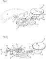
- the first embodiment illustrated in figures 1 , 3 and 4 is an automatic winding mechanism for a timepiece comprising a movement having at least two driving members, each comprising at least one barrel, supplying independent mechanisms, that is to say that each motor organ feeds exclusively its own mechanism without interaction with the mechanism driven by the other motor member.
- These independent mechanisms may be the driving mechanism of the movement, a stopwatch mechanism of the movement or a mechanism of a complication of the movement or an animation mechanism that includes the timepiece.
- the winding mechanism is automatic and includes winding means in the form of a winding mass 1, pivoted on a fixed part of the movement of the timepiece, comprising a drive wheel 2 in engagement with a sliding pinion 3, pivoted on a fixed part of the movement, and being able to move from an active position, in engagement with the wheel 4.1 of a winding device 4 to an inactive position , disengaged from the wheel 4.1 of the winding device 4 according to the direction of rotation of the automatic winding mass 1.
- winding means in the form of a winding mass 1, pivoted on a fixed part of the movement of the timepiece, comprising a drive wheel 2 in engagement with a sliding pinion 3, pivoted on a fixed part of the movement, and being able to move from an active position, in engagement with the wheel 4.1 of a winding device 4 to an inactive position , disengaged from the wheel 4.1 of the winding device 4 according to the direction of rotation of the automatic winding mass 1.
- the first drive member here a first cylinder 5, which is preferably the engine cylinder of the movement of the timepiece, comprises an axis 5.1, a cage 5.2 pivoted on the axis 5.1 and having on its periphery a suitable gearing 5.3 to drive the drive train of the movement and a cover 5.4.
- a motor spring is fixed at its inner end to the axis 5.1 of the first cylinder 5 and at its outer end, possibly via a sliding flange, to the cage 5.2 of the first cylinder 5.
- This first barrel 5 further comprises a ratchet 5.5 integral with its barrel axis 5.1 and whose teeth in wolf teeth cooperates with a non-illustrated pawl pivoted on the lid 5.4 of the barrel to allow a relative rotation of the axis 5.1 of the barrel 5 with respect to its cage 5.2 and its cover 5.4 that in the direction of winding of the mainspring.
- the axis 5.1 of this first cylinder 5 is integral with a first winding pinion 6.
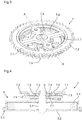
- This automatic winding mechanism also comprises a distribution differential 7 illustrated in FIGS. Figures 3 and 4 which comprises an epicyclic gear train.
- this differential comprises a first sun gear 7.1 pivoted on the shaft 5.1 of the first cylinder 5 having a gearing 7.2 in engagement with the pinion (not shown) of the winding device 4.
- This first sun gear 7.1 comprises spokes 7.3, 7.4 serving as a carrier.
- This distribution differential further comprises two satellites 7.5, 7.6 pivoted on the diametrically opposed radii 7.3, 7.4 respectively. These satellites 7.5, 7.6 meshing with the first winding pinion 6 of the first barrel 5 at two diametrically opposite points.
- the distribution differential 7 further comprises a second sun gear 7.7 pivoted on the axis 5.1 of the first cylinder 5 having an internal toothing 7.8 meshing with at least one and preferably two satellites 7.5, 7.6.
- the second sun gear 7.7 still has an external toothing 7.9.
- the distribution differential 7 can be positioned at another place, for example next to the first cylinder 5.
- the planetary 7.1, 7.7 pivot about an axis of the distribution differential which is parallel to the 5.1 shaft of the first cylinder, and the first winding pinion 6 is kinematically linked to an output wheel secured to the axis of the distribution differential.
- the second motor member here in the form of a second barrel 9, comprises a cage 9.1, provided with an external toothing 9.2 and an axis 9.3.
- This axis 9.3 is connected to the cage 9.1 by a motor spring.
- the axis 9.3 of this second barrel 9 includes a ratchet (not shown) in a conventional manner and a second winding pinion (not shown).
- the ratchet is subjected to the action of a pawl (not shown) allowing the relative rotation of the cage 9.1 with respect to the axis 9.3 of the second barrel that in the direction of the winding of the spring of the second barrel 9.
- external toothing 9.2 of this second barrel 9 is engaged with a drive train of an independent mechanism, a complication or an animation of the timepiece.
- the external toothing 7.9 of the second sun gear 7.7 of the distribution differential 7 is directly connected by a kinematic connection to the second winding pinion of the second barrel 9.
- a kinematic connection without differential comprises in the illustrated example a wheel 10 engaged with the outer toothing 7.9 of the second sun gear 7.7 of the distribution differential, a first mobile 11, a second wheel 12 and a third wheel 13 engaged with the second winding pinion second barrel 9.
- the second embodiment of the winding mechanism illustrated in FIG. figure 2 is a manual winding mechanism.
- the winding means comprise a winding stem 20 which actuates, when it is in the axial position of winding, a winding crown 21 via a kinematic connection 22, 23, 24.
- the winding crown 21 is engaged with the external toothing 7.2 of the first sun gear 7.1 of the distribution differential 7 mounted on the axis 5.1 of the first cylinder 5.
- the automatic winding mass 1 and its kinematic connection 2, 3, 4 is replaced by the winding stem and its kinematic connection 21, 22, 23, 24.
- the winding mechanism could be automatic and manual, the first sun gear 7.1 of the distribution differential 7 mounted on the first cylinder 5 being kinematically connected on the one hand to the automatic winding mass 1 and on the other hand to the winding crown 20.
- a first torque is transmitted (directly or indirectly) to the axis 5.1 of the first cylinder 5 through the distribution differential 7, in the example illustrated by means of the satellites 7.5, 7.6 and the first winding pinion 6 and drives the axis 5.1 of the first cylinder 5 at a first speed of rotation.
- a second pair is transmitted to the axis of the second cylinder by the second sun gear 7.7 of the distribution differential 7 and the kinematic connection 10, 11, 12, 13 thereof to the axis 9.1 of the second cylinder 9 and causes the axis 9.1 of the second barrel 9 at a second speed of rotation, generally lower than the first speed.
- the distribution differential 7 receives a winding torque of the winding means and distributes this torque unequally between the first motor member and the second motor unit.
- the distribution differential can be adapted to distribute the winding torque to more than two motor members.
- the first barrel 5 for driving the watch movement relative to the second barrel 9 for driving a secondary mechanism of the timepiece, for example an animation mechanism.
Landscapes
- Physics & Mathematics (AREA)
- General Physics & Mathematics (AREA)
- Measurement Of Unknown Time Intervals (AREA)
Claims (14)
- Aufzugsmechanismus für ein Zeitmessgerät, dessen Bewegung automatische und/oder manuelle Aufzugsmittel aufweist, die mindestens einem ersten Antriebsorgan (5) und einem zweiten Antriebsorgan (9), die einen ersten und einen zweiten unabhängigen Mechanismus antreiben, ein Aufzugsdrehmoment bereitstellen, dadurch gekennzeichnet, dass er ein Verteilungsdifferential (7) aufweist, das ein Aufzugsdrehmoment der Aufzugsmittel aufnimmt und dieses Drehmoment ungleichmäßig zwischen dem ersten Antriebsorgan (5) und dem zweiten Antriebsorgan (9) verteilt.
- Mechanismus nach Anspruch 1, dadurch gekennzeichnet, dass das Verteilungsdifferential (7) ein Planetengetriebe (7.1, 7.2, 7.3, 7.4, 7.5, 7.6, 7.7, 7.8, 7.9) aufweist.
- Mechanismus nach Anspruch 2, dadurch gekennzeichnet, dass das Verteilungsdifferential (7) ein erstes Sonnenrad (7.1) aufweist, das um eine Achse des Verteilungsdifferentials drehbar ist, wobei mindestens ein Satellitenrad (7.5, 7.6), das um das erste Sonnenrad (7.1) drehbar ist, einerseits in ein Ausgangsrad, das mit der Achse des Verteilungsdifferentials fest verbunden ist, und andererseits in ein zweites Sonnenrad (7.7) eingreift, das um die Achse des Verteilungsdifferentials drehbar ist, wobei das erste Sonnenrad (7.1) kinematisch mit den Aufzugsmitteln verbunden ist, wobei das Ausgangsrad kinematisch mit dem ersten Antriebsorgan (5) verbunden ist und das zweite Sonnenrad (7.7) kinematisch mit dem zweiten Antriebsorgan (9) verbunden ist.
- Mechanismus nach Anspruch 3, dadurch gekennzeichnet, dass eine kinematische Verbindung (10, 11, 12, 13) eine Verzahnung (7.9) des zweiten Sonnenrads (7.7) direkt mit dem zweiten Antriebsorgan (9) verbindet.
- Mechanismus nach Anspruch 4, dadurch gekennzeichnet, dass jedes Satellitenrad (7.5, 7.6) in eine innere Verzahnung (7.8) des zweiten Sonnenrads (7.7) eingreift, und dadurch, dass die kinematische Verbindung (10, 11, 12, 13) die Verzahnung (7.9) des zweiten Sonnenrads (7.7) mit dem zweiten Antriebsorgan (9) verbindet.
- Mechanismus nach einem der Ansprüche 3 bis 5, dadurch gekennzeichnet, dass das erste Antriebsorgan ein erstes Federhaus (5) aufweist und das zweite Antriebsorgan ein zweites Federhaus (9) aufweist, wobei das Ausgangsrad kinematisch mit einem ersten Aufzugsritzel (6) verbunden ist, das mit der Welle des ersten Federhauses (5) fest verbunden ist, und wobei das zweite Sonnenrad (7.7) kinematisch mit einem zweiten Aufzugsritzel verbunden ist, das mit der Welle (9.3) des zweiten Federhauses (9) fest verbunden ist.
- Mechanismus nach Anspruch 6, dadurch gekennzeichnet, dass die Achse des Differentials durch die Welle (5.1) des ersten Federhauses (5) gebildet ist, wobei das Ausgangsrad des Verteilungsdifferentials das erste Aufzugsritzel (6) des ersten Federhauses (5) ist.
- Mechanismus nach Anspruch 6, dadurch gekennzeichnet, dass die Achse des Verteilungsdifferentials parallel zu der Welle (5.1) des ersten Federhauses (5) ist.
- Mechanismus nach einem der Ansprüche 3 bis 8, dadurch gekennzeichnet, dass das Verteilungsdifferential (7) zwei Satellitenräder (7.5, 7.6) aufweist.
- Mechanismus nach einem der Ansprüche 3 bis 9, dadurch gekennzeichnet, dass das erste Sonnenrad (7.1) eine äußere Verzahnung (7.2) aufweist.
- Mechanismus nach einem der Ansprüche 3 bis 10, dadurch gekennzeichnet, dass das erste Sonnenrad (7.1) kinematisch mit einer Masse des automatischen Aufzugs (1) der Bewegung verbunden ist.
- Mechanismus nach einem der Ansprüche 3 bis 11, dadurch gekennzeichnet, dass das erste Sonnenrad (7.1) kinematisch mit einer Aufzugswelle (20) der Bewegung verbunden ist, wenn diese in der Aufzugsposition ist.
- Mechanismus nach einem der vorhergehenden Ansprüche, dadurch gekennzeichnet, dass das erste Antriebsorgan (5) ein Uhrwerk des Zeitmessgeräts antreibt und das zweite Antriebsorgan (9) einen Sekundärmechanismus des Zeitmessgeräts antreibt, wobei das Aufziehen des ersten Antriebsorgans (5) gegenüber dem Aufziehen des zweiten Antriebsorgans (9) bevorzugt wird.
- Zeitmessgerät, umfassend automatische und/oder manuelle Aufzugsmittel, dadurch gekennzeichnet, dass es mit einem Aufzugsmechanismus nach einem der Ansprüche 1 bis 13 ausgestattet ist.
Applications Claiming Priority (1)
| Application Number | Priority Date | Filing Date | Title |
|---|---|---|---|
| CH00481/16A CH712338A1 (fr) | 2016-04-13 | 2016-04-13 | Mécanisme de remontage pour une pièce d'horlogerie comportant au moins deux barillets, et pièce d'horlogerie comprenant un tel mécanisme. |
Publications (2)
| Publication Number | Publication Date |
|---|---|
| EP3232275A1 EP3232275A1 (de) | 2017-10-18 |
| EP3232275B1 true EP3232275B1 (de) | 2019-02-20 |
Family
ID=55794824
Family Applications (1)
| Application Number | Title | Priority Date | Filing Date |
|---|---|---|---|
| EP17162108.9A Active EP3232275B1 (de) | 2016-04-13 | 2017-03-21 | Aufziehmechanismus für eine uhr, der mindestens zwei federhäuser umfasst, und uhr, die einen solchen mechanismus umfasst |
Country Status (2)
| Country | Link |
|---|---|
| EP (1) | EP3232275B1 (de) |
| CH (1) | CH712338A1 (de) |
Family Cites Families (3)
| Publication number | Priority date | Publication date | Assignee | Title |
|---|---|---|---|---|
| US1245245A (en) * | 1917-03-28 | 1917-11-06 | Edward T Lewis | Alarm-clock. |
| DE317294C (de) * | 1918-08-08 | 1919-12-13 | Paul Schröder | Aufziehvorrichtung für uhren mit mehreren werken |
| DE542580C (de) * | 1928-02-25 | 1932-01-26 | Carl Doll | Uhr mit elektrischem Aufzug |
-
2016
- 2016-04-13 CH CH00481/16A patent/CH712338A1/fr not_active Application Discontinuation
-
2017
- 2017-03-21 EP EP17162108.9A patent/EP3232275B1/de active Active
Non-Patent Citations (1)
| Title |
|---|
| None * |
Also Published As
| Publication number | Publication date |
|---|---|
| CH712338A1 (fr) | 2017-10-13 |
| EP3232275A1 (de) | 2017-10-18 |
Similar Documents
| Publication | Publication Date | Title |
|---|---|---|
| EP1970778B1 (de) | Uhr mit Anzeige der Gangreserve | |
| EP1046965A1 (de) | Uhrwerk mit Schwungmassen-Selbstaufzug | |
| EP2515186B1 (de) | Gear-train for timepiece | |
| EP2376986B1 (de) | Uhrwerk mit automatischer aufzugvorrichtung und bewegungshemmung | |
| EP1582943B1 (de) | Uhrwerk mit mehreren Federhäusern | |
| EP3106927B1 (de) | Gangreserveanzeige für uhr | |
| EP1139182B1 (de) | Anzeigemechanismus der Gangreserve einer Uhr und mit diesem Mechanismus versehene Uhr | |
| EP1978419B1 (de) | Aufzugsvorrichtung mit unidirektionale Kupplung | |
| EP2634650A2 (de) | Automatischer bidirektionaler Aufziehmechanismus für Uhrwerk | |
| EP2313812B1 (de) | Uhrwerk mit integrierter automatischer aufzugvorrichtung | |
| EP0188164B1 (de) | Lenkungsblock für ein Kraftfahrzeug mit festem zentralem Kissen | |
| EP3246763B1 (de) | Schnellkorrekturmechanismus für uhr | |
| EP3232275A1 (de) | Aufziehmechanismus für eine uhr, der mindestens zwei federhäuser umfasst, und uhr, die einen solchen mechanismus umfasst | |
| EP3555707B1 (de) | Uhrwerk mit automatischer montage | |
| EP0568499A1 (de) | Vorrichtung zur Anzeige der Gangreserve einer Uhr | |
| EP3306415A1 (de) | Mechanisches uhrwerk mit erfassung der gangreserve | |
| CH719259A2 (fr) | Système de remontage automatique pour mouvement d'horlogerie. | |
| EP3376309B1 (de) | Aufziehmechanismus einer uhr | |
| EP3654109B1 (de) | Uhr, die zwei energiequellen besitzt | |
| EP3627232B1 (de) | Uhrwerk mit automatischem aufzug, das stundenzeiger auf der seite des rotors umfasst | |
| EP2869135A1 (de) | Schneckesystem | |
| CH678474B5 (de) | ||
| CH717086A2 (fr) | Mécanisme de rouage, mouvement et pièce d'horlogerie. | |
| CH711132B1 (fr) | Mécanisme d'horlogerie comportant un moteur et un indicateur de réserve de marche. | |
| CH713384B1 (fr) | Procédé de prise d'information mécanique dans un mouvement horloger, notamment pour indicateur de réserve de marche. |
Legal Events
| Date | Code | Title | Description |
|---|---|---|---|
| PUAI | Public reference made under article 153(3) epc to a published international application that has entered the european phase |
Free format text: ORIGINAL CODE: 0009012 |
|
| STAA | Information on the status of an ep patent application or granted ep patent |
Free format text: STATUS: THE APPLICATION HAS BEEN PUBLISHED |
|
| AK | Designated contracting states |
Kind code of ref document: A1 Designated state(s): AL AT BE BG CH CY CZ DE DK EE ES FI FR GB GR HR HU IE IS IT LI LT LU LV MC MK MT NL NO PL PT RO RS SE SI SK SM TR |
|
| AX | Request for extension of the european patent |
Extension state: BA ME |
|
| STAA | Information on the status of an ep patent application or granted ep patent |
Free format text: STATUS: REQUEST FOR EXAMINATION WAS MADE |
|
| 17P | Request for examination filed |
Effective date: 20180405 |
|
| RBV | Designated contracting states (corrected) |
Designated state(s): AL AT BE BG CH CY CZ DE DK EE ES FI FR GB GR HR HU IE IS IT LI LT LU LV MC MK MT NL NO PL PT RO RS SE SI SK SM TR |
|
| GRAP | Despatch of communication of intention to grant a patent |
Free format text: ORIGINAL CODE: EPIDOSNIGR1 |
|
| STAA | Information on the status of an ep patent application or granted ep patent |
Free format text: STATUS: GRANT OF PATENT IS INTENDED |
|
| INTG | Intention to grant announced |
Effective date: 20181012 |
|
| GRAS | Grant fee paid |
Free format text: ORIGINAL CODE: EPIDOSNIGR3 |
|
| GRAA | (expected) grant |
Free format text: ORIGINAL CODE: 0009210 |
|
| STAA | Information on the status of an ep patent application or granted ep patent |
Free format text: STATUS: THE PATENT HAS BEEN GRANTED |
|
| AK | Designated contracting states |
Kind code of ref document: B1 Designated state(s): AL AT BE BG CH CY CZ DE DK EE ES FI FR GB GR HR HU IE IS IT LI LT LU LV MC MK MT NL NO PL PT RO RS SE SI SK SM TR |
|
| REG | Reference to a national code |
Ref country code: GB Ref legal event code: FG4D Free format text: NOT ENGLISH |
|
| REG | Reference to a national code |
Ref country code: CH Ref legal event code: EP |
|
| REG | Reference to a national code |
Ref country code: DE Ref legal event code: R096 Ref document number: 602017002160 Country of ref document: DE |
|
| REG | Reference to a national code |
Ref country code: CH Ref legal event code: NV Representative=s name: MICHELI AND CIE SA, CH Ref country code: AT Ref legal event code: REF Ref document number: 1099012 Country of ref document: AT Kind code of ref document: T Effective date: 20190315 |
|
| REG | Reference to a national code |
Ref country code: IE Ref legal event code: FG4D Free format text: LANGUAGE OF EP DOCUMENT: FRENCH |
|
| REG | Reference to a national code |
Ref country code: LT Ref legal event code: MG4D Ref country code: NL Ref legal event code: MP Effective date: 20190220 |
|
| PG25 | Lapsed in a contracting state [announced via postgrant information from national office to epo] |
Ref country code: SE Free format text: LAPSE BECAUSE OF FAILURE TO SUBMIT A TRANSLATION OF THE DESCRIPTION OR TO PAY THE FEE WITHIN THE PRESCRIBED TIME-LIMIT Effective date: 20190220 Ref country code: PT Free format text: LAPSE BECAUSE OF FAILURE TO SUBMIT A TRANSLATION OF THE DESCRIPTION OR TO PAY THE FEE WITHIN THE PRESCRIBED TIME-LIMIT Effective date: 20190620 Ref country code: NO Free format text: LAPSE BECAUSE OF FAILURE TO SUBMIT A TRANSLATION OF THE DESCRIPTION OR TO PAY THE FEE WITHIN THE PRESCRIBED TIME-LIMIT Effective date: 20190520 Ref country code: FI Free format text: LAPSE BECAUSE OF FAILURE TO SUBMIT A TRANSLATION OF THE DESCRIPTION OR TO PAY THE FEE WITHIN THE PRESCRIBED TIME-LIMIT Effective date: 20190220 Ref country code: LT Free format text: LAPSE BECAUSE OF FAILURE TO SUBMIT A TRANSLATION OF THE DESCRIPTION OR TO PAY THE FEE WITHIN THE PRESCRIBED TIME-LIMIT Effective date: 20190220 |
|
| PG25 | Lapsed in a contracting state [announced via postgrant information from national office to epo] |
Ref country code: IS Free format text: LAPSE BECAUSE OF FAILURE TO SUBMIT A TRANSLATION OF THE DESCRIPTION OR TO PAY THE FEE WITHIN THE PRESCRIBED TIME-LIMIT Effective date: 20190620 Ref country code: GR Free format text: LAPSE BECAUSE OF FAILURE TO SUBMIT A TRANSLATION OF THE DESCRIPTION OR TO PAY THE FEE WITHIN THE PRESCRIBED TIME-LIMIT Effective date: 20190521 Ref country code: NL Free format text: LAPSE BECAUSE OF FAILURE TO SUBMIT A TRANSLATION OF THE DESCRIPTION OR TO PAY THE FEE WITHIN THE PRESCRIBED TIME-LIMIT Effective date: 20190220 Ref country code: RS Free format text: LAPSE BECAUSE OF FAILURE TO SUBMIT A TRANSLATION OF THE DESCRIPTION OR TO PAY THE FEE WITHIN THE PRESCRIBED TIME-LIMIT Effective date: 20190220 Ref country code: LV Free format text: LAPSE BECAUSE OF FAILURE TO SUBMIT A TRANSLATION OF THE DESCRIPTION OR TO PAY THE FEE WITHIN THE PRESCRIBED TIME-LIMIT Effective date: 20190220 Ref country code: HR Free format text: LAPSE BECAUSE OF FAILURE TO SUBMIT A TRANSLATION OF THE DESCRIPTION OR TO PAY THE FEE WITHIN THE PRESCRIBED TIME-LIMIT Effective date: 20190220 Ref country code: BG Free format text: LAPSE BECAUSE OF FAILURE TO SUBMIT A TRANSLATION OF THE DESCRIPTION OR TO PAY THE FEE WITHIN THE PRESCRIBED TIME-LIMIT Effective date: 20190520 |
|
| REG | Reference to a national code |
Ref country code: AT Ref legal event code: MK05 Ref document number: 1099012 Country of ref document: AT Kind code of ref document: T Effective date: 20190220 |
|
| PG25 | Lapsed in a contracting state [announced via postgrant information from national office to epo] |
Ref country code: RO Free format text: LAPSE BECAUSE OF FAILURE TO SUBMIT A TRANSLATION OF THE DESCRIPTION OR TO PAY THE FEE WITHIN THE PRESCRIBED TIME-LIMIT Effective date: 20190220 Ref country code: AL Free format text: LAPSE BECAUSE OF FAILURE TO SUBMIT A TRANSLATION OF THE DESCRIPTION OR TO PAY THE FEE WITHIN THE PRESCRIBED TIME-LIMIT Effective date: 20190220 Ref country code: CZ Free format text: LAPSE BECAUSE OF FAILURE TO SUBMIT A TRANSLATION OF THE DESCRIPTION OR TO PAY THE FEE WITHIN THE PRESCRIBED TIME-LIMIT Effective date: 20190220 Ref country code: IT Free format text: LAPSE BECAUSE OF FAILURE TO SUBMIT A TRANSLATION OF THE DESCRIPTION OR TO PAY THE FEE WITHIN THE PRESCRIBED TIME-LIMIT Effective date: 20190220 Ref country code: EE Free format text: LAPSE BECAUSE OF FAILURE TO SUBMIT A TRANSLATION OF THE DESCRIPTION OR TO PAY THE FEE WITHIN THE PRESCRIBED TIME-LIMIT Effective date: 20190220 Ref country code: DK Free format text: LAPSE BECAUSE OF FAILURE TO SUBMIT A TRANSLATION OF THE DESCRIPTION OR TO PAY THE FEE WITHIN THE PRESCRIBED TIME-LIMIT Effective date: 20190220 Ref country code: SK Free format text: LAPSE BECAUSE OF FAILURE TO SUBMIT A TRANSLATION OF THE DESCRIPTION OR TO PAY THE FEE WITHIN THE PRESCRIBED TIME-LIMIT Effective date: 20190220 Ref country code: ES Free format text: LAPSE BECAUSE OF FAILURE TO SUBMIT A TRANSLATION OF THE DESCRIPTION OR TO PAY THE FEE WITHIN THE PRESCRIBED TIME-LIMIT Effective date: 20190220 |
|
| REG | Reference to a national code |
Ref country code: DE Ref legal event code: R097 Ref document number: 602017002160 Country of ref document: DE |
|
| PG25 | Lapsed in a contracting state [announced via postgrant information from national office to epo] |
Ref country code: LU Free format text: LAPSE BECAUSE OF NON-PAYMENT OF DUE FEES Effective date: 20190321 Ref country code: PL Free format text: LAPSE BECAUSE OF FAILURE TO SUBMIT A TRANSLATION OF THE DESCRIPTION OR TO PAY THE FEE WITHIN THE PRESCRIBED TIME-LIMIT Effective date: 20190220 Ref country code: SM Free format text: LAPSE BECAUSE OF FAILURE TO SUBMIT A TRANSLATION OF THE DESCRIPTION OR TO PAY THE FEE WITHIN THE PRESCRIBED TIME-LIMIT Effective date: 20190220 |
|
| REG | Reference to a national code |
Ref country code: BE Ref legal event code: MM Effective date: 20190331 |
|
| PLBE | No opposition filed within time limit |
Free format text: ORIGINAL CODE: 0009261 |
|
| STAA | Information on the status of an ep patent application or granted ep patent |
Free format text: STATUS: NO OPPOSITION FILED WITHIN TIME LIMIT |
|
| PG25 | Lapsed in a contracting state [announced via postgrant information from national office to epo] |
Ref country code: AT Free format text: LAPSE BECAUSE OF FAILURE TO SUBMIT A TRANSLATION OF THE DESCRIPTION OR TO PAY THE FEE WITHIN THE PRESCRIBED TIME-LIMIT Effective date: 20190220 Ref country code: MC Free format text: LAPSE BECAUSE OF FAILURE TO SUBMIT A TRANSLATION OF THE DESCRIPTION OR TO PAY THE FEE WITHIN THE PRESCRIBED TIME-LIMIT Effective date: 20190220 |
|
| 26N | No opposition filed |
Effective date: 20191121 |
|
| PG25 | Lapsed in a contracting state [announced via postgrant information from national office to epo] |
Ref country code: IE Free format text: LAPSE BECAUSE OF NON-PAYMENT OF DUE FEES Effective date: 20190321 |
|
| PG25 | Lapsed in a contracting state [announced via postgrant information from national office to epo] |
Ref country code: BE Free format text: LAPSE BECAUSE OF NON-PAYMENT OF DUE FEES Effective date: 20190331 Ref country code: SI Free format text: LAPSE BECAUSE OF FAILURE TO SUBMIT A TRANSLATION OF THE DESCRIPTION OR TO PAY THE FEE WITHIN THE PRESCRIBED TIME-LIMIT Effective date: 20190220 |
|
| PG25 | Lapsed in a contracting state [announced via postgrant information from national office to epo] |
Ref country code: TR Free format text: LAPSE BECAUSE OF FAILURE TO SUBMIT A TRANSLATION OF THE DESCRIPTION OR TO PAY THE FEE WITHIN THE PRESCRIBED TIME-LIMIT Effective date: 20190220 |
|
| PG25 | Lapsed in a contracting state [announced via postgrant information from national office to epo] |
Ref country code: MT Free format text: LAPSE BECAUSE OF FAILURE TO SUBMIT A TRANSLATION OF THE DESCRIPTION OR TO PAY THE FEE WITHIN THE PRESCRIBED TIME-LIMIT Effective date: 20190220 |
|
| PG25 | Lapsed in a contracting state [announced via postgrant information from national office to epo] |
Ref country code: CY Free format text: LAPSE BECAUSE OF FAILURE TO SUBMIT A TRANSLATION OF THE DESCRIPTION OR TO PAY THE FEE WITHIN THE PRESCRIBED TIME-LIMIT Effective date: 20190220 |
|
| PG25 | Lapsed in a contracting state [announced via postgrant information from national office to epo] |
Ref country code: HU Free format text: LAPSE BECAUSE OF FAILURE TO SUBMIT A TRANSLATION OF THE DESCRIPTION OR TO PAY THE FEE WITHIN THE PRESCRIBED TIME-LIMIT; INVALID AB INITIO Effective date: 20170321 |
|
| PG25 | Lapsed in a contracting state [announced via postgrant information from national office to epo] |
Ref country code: MK Free format text: LAPSE BECAUSE OF FAILURE TO SUBMIT A TRANSLATION OF THE DESCRIPTION OR TO PAY THE FEE WITHIN THE PRESCRIBED TIME-LIMIT Effective date: 20190220 |
|
| REG | Reference to a national code |
Ref country code: DE Ref legal event code: R081 Ref document number: 602017002160 Country of ref document: DE Owner name: RICHEMONT INTERNATIONAL SA, CH Free format text: FORMER OWNER: VAN CLEEF&ARPELS SA, VILLARS-SUR-GLANE, CH |
|
| REG | Reference to a national code |
Ref country code: GB Ref legal event code: 732E Free format text: REGISTERED BETWEEN 20241024 AND 20241030 |
|
| PGFP | Annual fee paid to national office [announced via postgrant information from national office to epo] |
Ref country code: CH Payment date: 20250401 Year of fee payment: 9 |
|
| REG | Reference to a national code |
Ref country code: CH Ref legal event code: U11 Free format text: ST27 STATUS EVENT CODE: U-0-0-U10-U11 (AS PROVIDED BY THE NATIONAL OFFICE) Effective date: 20260401 |
|
| PGFP | Annual fee paid to national office [announced via postgrant information from national office to epo] |
Ref country code: GB Payment date: 20260324 Year of fee payment: 10 |
|
| PGFP | Annual fee paid to national office [announced via postgrant information from national office to epo] |
Ref country code: DE Payment date: 20260319 Year of fee payment: 10 |
|
| PGFP | Annual fee paid to national office [announced via postgrant information from national office to epo] |
Ref country code: FR Payment date: 20260320 Year of fee payment: 10 |