EP3548203B1 - Méthode d'utilisation d'une machine de coulée par chaine pour couler du métal - Google Patents
Méthode d'utilisation d'une machine de coulée par chaine pour couler du métal Download PDFInfo
- Publication number
- EP3548203B1 EP3548203B1 EP17811506.9A EP17811506A EP3548203B1 EP 3548203 B1 EP3548203 B1 EP 3548203B1 EP 17811506 A EP17811506 A EP 17811506A EP 3548203 B1 EP3548203 B1 EP 3548203B1
- Authority
- EP
- European Patent Office
- Prior art keywords
- caterpillar
- casting
- actuator
- relative
- control device
- Prior art date
- Legal status (The legal status is an assumption and is not a legal conclusion. Google has not performed a legal analysis and makes no representation as to the accuracy of the status listed.)
- Active
Links
Images


Classifications
-
- B—PERFORMING OPERATIONS; TRANSPORTING
- B22—CASTING; POWDER METALLURGY
- B22D—CASTING OF METALS; CASTING OF OTHER SUBSTANCES BY THE SAME PROCESSES OR DEVICES
- B22D11/00—Continuous casting of metals, i.e. casting in indefinite lengths
- B22D11/06—Continuous casting of metals, i.e. casting in indefinite lengths into moulds with travelling walls, e.g. with rolls, plates, belts, caterpillars
- B22D11/0608—Continuous casting of metals, i.e. casting in indefinite lengths into moulds with travelling walls, e.g. with rolls, plates, belts, caterpillars formed by caterpillars
-
- B—PERFORMING OPERATIONS; TRANSPORTING
- B22—CASTING; POWDER METALLURGY
- B22D—CASTING OF METALS; CASTING OF OTHER SUBSTANCES BY THE SAME PROCESSES OR DEVICES
- B22D11/00—Continuous casting of metals, i.e. casting in indefinite lengths
- B22D11/16—Controlling or regulating processes or operations
-
- B—PERFORMING OPERATIONS; TRANSPORTING
- B22—CASTING; POWDER METALLURGY
- B22D—CASTING OF METALS; CASTING OF OTHER SUBSTANCES BY THE SAME PROCESSES OR DEVICES
- B22D11/00—Continuous casting of metals, i.e. casting in indefinite lengths
- B22D11/16—Controlling or regulating processes or operations
- B22D11/168—Controlling or regulating processes or operations for adjusting the mould size or mould taper
Definitions
- the invention relates to a method for producing a cast material from liquid metal according to the preamble of claim 1.
- horizontal ingot casting machines are known, in particular for the production of aluminum alloys, which work in the manner of a rotating caterpillar casting machine.
- a casting machine is, for example, off EP 1 704 005 B1 or WO 95/27145 known.
- the cooling elements of the casting machine on the straight sections or runs of casting beads arranged opposite one another form the wall of a moving casting mold.
- the casting beads each consist of a large number of endlessly interconnected cooling blocks that are transported along the orbits of the beads.
- the cooling blocks are mounted on support elements that are placed on chains and are thus articulated like links in a chain.
- this ingot casting machine comprises a spindle lifting device which is in operative connection with the four corner areas of the ingot casting machine.
- measuring cells and dial gauges are installed when the spindle lifting device is used.
- the disadvantage here is that the servomotors or actuators of the spindle lifting device are not synchronized, that defined positions for the casting beads cannot be repeatedly approached, that no active influence on the casting gap is possible, and that long set-up times are required to open the unit formed from the casting beads to set a new operating state.
- a Another disadvantage is that a position of the casting beads relative to one another cannot be controlled exactly, with automation by means of a control / regulating concept likewise not being given.
- the invention is based on the object of optimizing a method for producing a cast material from liquid metal with regard to the variability of the production process.
- the present invention provides a method of making a cast from liquid metal.
- the liquid metal is poured into a moving casting mold which is formed between cooling blocks which are attached to support elements which are moved in a transport direction along two oppositely arranged endless horizontal circulating tracks.
- the inclination of a unit formed from the upper and lower bead is set relative to the horizontal, in particular during casting, in that at least one actuator, which is operatively connected to the unit formed from the upper and lower bead, is controlled .
- the inclination of either the upper or the lower caterpillar is changed in the direction of its longitudinal axis relative to the respective other caterpillar by at least one actuator, which is connected to a frame device, on one of which is an endless one for this caterpillar Orbit forming guide rail is attached, is operatively connected, is controlled.
- the at least one actuator is controlled by a control device.
- the transport direction in which the support elements with the cooling blocks attached to them are moved along the respective guide rails and the thereby formed orbits is synonymous with the casting direction in which the liquid metal enters the moving casting mold between the cooling blocks is formed in the straight sections of the opposite horizontal orbits, is potted.
- the mentioned adjustment of the unit formed from the caterpillars or at least one caterpillar relative to the other caterpillar with regard to its inclination is achieved by controlling at least one actuator which is operatively connected to a frame device on which the guide rails assigned to the caterpillars are attached.
- the at least one actuator is force-regulated by means of the control device as a function of at least one predetermined process variable, this process variable being a contact force of the upper bead with a lateral guide device.
- the invention is based on the essential knowledge that by controlling the at least one actuator a reproducible setting for the caterpillar casting machine is possible, namely with regard to the inclination of either the unit formed from the upper and lower caterpillars relative to the horizontal or one caterpillar relative to the other Caterpillar.
- An adjustment or change of the inclination of the complete unit formed from the upper and lower bead in its inclination relative to the horizontal can take place in particular during casting, ie at the beginning of a casting process. This allows the flow rate of the liquid metal within the casting mold to be regulated.
- a greater "slope" is created for the moving casting mold in or along the transport direction, because the outlet area of the casting mold is arranged higher than its Inlet area.
- the outlet area of the To pivot the casting mold downwards so that gravity contributes to bringing the liquid cast material into the casting machine or its moving casting mold. This allows the heat transfer from the cast material to the mold, ie to the cooling blocks and thus the temperature control of the cast material or one of it generated bands are affected.
- Such a change in the inclination of the unit formed from the upper and lower bead can also take place automatically during the casting process.
- the inclination of only one caterpillar is variable or adjusted relative to the other caterpillar. In this way, either an exact plane parallelism of the two caterpillars can be achieved on their opposite strands, or a specifically wedge-shaped cast strip profile can be set.
- this actuator can be actuated by an electric motor, pneumatically or hydraulically.
- the at least one actuator can be position-regulated by means of the control device as a function of at least one predetermined process variable.
- This predetermined process variable can be selected from the group formed in particular from the product temperature, the wear of the machine components involved, the type of metal being cast, the speed of the caterpillars, the selected casting thickness and / or the casting width of the cast material.
- the at least one actuator can be force-regulated by means of the control device as a function of a further predetermined process variable, this process variable being formed from the cast metal type.
- a model is stored in the control device by means of which the at least one actuator is controlled.
- automation for the control of the at least one actuator is also possible during the casting process in order to change the inclination either of one caterpillar relative to the other caterpillar, or of the unit formed from both caterpillars.
- an electrically synchronized setting of the caterpillar (s) can take place on the basis of a stored model, which makes it possible to position a caterpillar in any direction in a targeted manner and to move to a position defined for this purpose more easily.
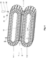
- a caterpillar casting machine 10 and their components explained, which are required for a method according to the invention for producing a cast material 11 (cf. Fig. 2 ) made of liquid metal, in particular aluminum, is used.
- a cast material 11 cf. Fig. 2
- the same features in the drawing are each provided with the same reference symbols. At this point, it is pointed out separately that the drawing is only shown in a simplified manner and, in particular, without a scale.
- the caterpillar casting machine 10 comprises an upper, first guide rail 12.1 and a lower, second guide rail 12.2. With these guide rails 12.1, 12.2 two oppositely arranged endless horizontal circulating tracks U for the caterpillar casting machine 10 are formed. A plurality of support elements 14 with cooling blocks 16 attached to them are guided along each guide rail 12 in such a way that a continuous chain of support elements 14 is formed, which is moved or transported in a transport direction T along the guide rails 16. To illustrate the operation of the present invention are in Fig. 1 only two support elements 14 with cooling blocks 16 attached to them are shown on each of the two guide rails 12.
- Fig. 1 shows that a casting mold 18 is formed between the cooling blocks 16, which come into opposition in the straight sections of the circumferential paths U formed by the guide rails 12.
- this casting mold 15 is a casting mold moving in the transport direction T.
- Fig. 2 shows a simplified side view of the caterpillar casting machine 10, in which the guide rails 12.1, 12.2 of Fig. 1 can be used.
- the caterpillar casting machine 10 comprises an upper caterpillar 14.1 and a lower caterpillar 14.2 which - as already explained above - are each formed from a plurality of support elements 14 and cooling blocks 16 attached to them, which run along the orbits U formed by the guide rails 14 in the transport direction T be moved.
- the caterpillars 14.1, 14.2 are each driven by drive wheels 13 which ensure a movement of the support elements 14 and the cooling blocks 16 attached to them around the orbits U.
- Liquid metal for example aluminum or an aluminum alloy
- a pouring nozzle 19 which is elongated and protrudes with its front end into the casting mold 18.
- a casting 11 is produced which - in the right-hand area of FIG Fig. 2 indicated - downstream of the caterpillars 14.1, 14.2 emerges from the casting gap 18 and is then fed to processing (not shown).
- Cooling of the cooling blocks 16 during the casting process is ensured by cooling devices (not shown). By means of these cooling devices, a cooling medium can be applied or sprayed onto the respective cooling blocks.
- the Fig. 3 shows a basically simplified side view of the two caterpillars 14.1, 14.2 of Fig. 2 .
- the transport direction T - seen in the plane of the drawing - is indicated from left to right, an inlet area of the moving casting mold 18 being symbolized by "E” and an outlet area of the casting mold 18 being symbolized by "A”.
- an actuator 26 (top right in the image area) is shown in principle in a simplified manner.
- Such an actuator 26 is used to adjust the inclination of either one caterpillar 14.1, 14.2 relative to the other caterpillar, or the inclination of a unit formed by the two caterpillars 14.1, 14.2 relative to the horizontal.
- the actuator 26 comprises an actuator 27 which is connected to a frame device 22 and to that extent is in operative connection therewith.
- guide rails 12.1, 12.2 are attached for the upper caterpillar 14.1 and lower caterpillar 14.2 (cf. Fig. 1, Fig. 2 ).
- the caterpillar casting machine 10 comprises a control device 28, which is shown in Fig. 2 is symbolized simplified by a rectangle.
- a total of four actuators 26 can be provided, which are operatively connected to the frame device 22 on which, for example, the guide rail 12.1 for the upper caterpillar 14.1 is attached.
- the actuators 26 can be attached to a (in Fig. 3 not shown) machine frame or the like be attached.
- the actuator 26 which is shown in the image area at the top right by a rectangle, the other three actuators simplified only symbolized by an "X", these actuators in the same way with their actuator 27 with the frame device 22 that of the upper caterpillar 14.1 is assigned, are operatively connected.
- the guide rail 12.2 for the lower caterpillar 14.1 can be fixedly attached to a machine frame (not shown).
- Deviating from the representation according to Fig. 3 it is also possible to provide a number of actuators 26 that is greater than or less than four.
- FIG. 4 Another embodiment of the track caster 10 is shown.
- the guide rails 12.1, 12.2 for the upper and lower caterpillars 14.1, 14.2 are attached to a common frame device 22, this frame device 22 being rotatably mounted on a machine frame 24 via a swivel joint 23.
- At least one actuator 26 is operatively connected with its actuator 27 to the frame device 22.
- a position of the frame device 22, and thus also a unit formed from the two caterpillars 14.1, 14.2 can be adjusted when the actuator 26 is actuated, for example with regard to an inclination relative to the horizontal.
- a position of the two caterpillars 14.1, 14.2 can be changed by activating the actuators 26 in such a way that - as shown - the outlet area A of the casting mold 18 (shown on the right in the image area) is lowered or downwards compared to the inlet area E of the casting mold 18 is pivoted.
- FIG Fig. 3 and Fig. 4 a combination of the embodiments of FIG Fig. 3 and Fig. 4 is possible.
- the first and second caterpillars 14.1, 14.2 can be attached to a common frame device 22.
- one of the two caterpillars for example the upper one
- the caterpillar 14.1 with its associated guide rail 12.1 and a frame device 22 attached to it, can be individually operatively connected to further actuators 26, so that this caterpillar 14.1 can be changed in its position relative to the other caterpillar 14.2.
Landscapes
- Engineering & Computer Science (AREA)
- Mechanical Engineering (AREA)
- Casting Devices For Molds (AREA)
- Continuous Casting (AREA)
- Molds, Cores, And Manufacturing Methods Thereof (AREA)
Claims (2)
- Procédé destiné à la fabrication d'un produit de coulée (11) à partir d'un métal liquide, dans lequel on verse le métal liquide dans une lingotière (18) apte à se déplacer, qui est formée entre deux cloches de refroidissement (16) qui sont montées sur des éléments de support (14) qui se déplacent le long de respectivement deux voies périphériques horizontales sans fin (U) disposées face à face, dans une direction de transport (T) ; dans lequel on obtient, avec les éléments de support (14) qui se déplacent le long des voies périphériques (U), une chenille supérieure (14.1) et une chenille inférieure (14.2) ; dans lequel l'inclinaison de la chenille supérieure et/ou de la chenille inférieure (14.1, 14.2) est modifiée dans la direction de son axe longitudinal par rapport à celle de l'autre chenille respective (14.2, 14.1), par le fait de commander au moins un actionneur (26) par l'intermédiaire d'un mécanisme de commande (28) ; caractérisé en ce que l'actionneur (26) est relié de manière fonctionnelle à un mécanisme (22) faisant office de bâti, contre lequel est monté un rail de guidage (12.1, 12.2) qui forme la voile périphérique sans fin (U) pour la chenille (14.1, 14.2) ; et en ce que l'inclinaison d'une unité formée par la chenille supérieure (14.1) et/ou la chenille inférieure (14.2) par rapport à l'horizontale et/ou d'une chenille (14.1, 14.2) par rapport à respectivement l'autre chenille (14.2, 14.1) est réglée, respectivement est modifiée de manière automatique par l'intermédiaire du mécanisme de commande (28) en fonction d'un paramètre de processus qui a été prédéfini au cours du processus de coulée, ledit au moins un actionneur (26) faisant l'objet d'un réglage automatique par la force en fonction du paramètre de processus qui a été prédéfini et ce paramètre de processus représentant une force de contact par rapport à un mécanisme de réglage latéral.
- Procédé selon la revendication 1, caractérisé en ce que, dans le mécanisme de commande (28), on dépose un modèle qui est destiné à l'excitation dudit au moins un actionneur (26).
Applications Claiming Priority (2)
| Application Number | Priority Date | Filing Date | Title |
|---|---|---|---|
| DE102016223828 | 2016-11-30 | ||
| PCT/EP2017/080396 WO2018099828A1 (fr) | 2016-11-30 | 2017-11-24 | Machine de coulée à chenilles et procédé pour la fabrication d'un produit coulé à partir de métal liquide |
Publications (2)
| Publication Number | Publication Date |
|---|---|
| EP3548203A1 EP3548203A1 (fr) | 2019-10-09 |
| EP3548203B1 true EP3548203B1 (fr) | 2021-07-07 |
Family
ID=60629671
Family Applications (1)
| Application Number | Title | Priority Date | Filing Date |
|---|---|---|---|
| EP17811506.9A Active EP3548203B1 (fr) | 2016-11-30 | 2017-11-24 | Méthode d'utilisation d'une machine de coulée par chaine pour couler du métal |
Country Status (3)
| Country | Link |
|---|---|
| EP (1) | EP3548203B1 (fr) |
| DE (1) | DE102017221093A1 (fr) |
| WO (1) | WO2018099828A1 (fr) |
Citations (1)
| Publication number | Priority date | Publication date | Assignee | Title |
|---|---|---|---|---|
| US3605868A (en) * | 1969-02-24 | 1971-09-20 | Massimo Giadorou | Machine for the continuous casting of molten materials in iron molds or chills |
Family Cites Families (4)
| Publication number | Priority date | Publication date | Assignee | Title |
|---|---|---|---|---|
| JPH0724925B2 (ja) * | 1988-05-20 | 1995-03-22 | 新日本製鐵株式会社 | 双ベルト連続鋳造機の鋳造幅変更制御方法および装置 |
| US5645122A (en) | 1994-03-30 | 1997-07-08 | Lauener Engineering, Ltd. | Block fixation and adjustment in a continuous caster |
| TW331532B (en) * | 1995-11-14 | 1998-05-11 | Fataphunter Inc | The continuous caster and method for continuous casting a cast product |
| DE502004004685D1 (en) | 2004-01-14 | 2007-09-27 | Lamec Ag | Giessmaschine |
-
2017
- 2017-11-24 DE DE102017221093.1A patent/DE102017221093A1/de not_active Withdrawn
- 2017-11-24 EP EP17811506.9A patent/EP3548203B1/fr active Active
- 2017-11-24 WO PCT/EP2017/080396 patent/WO2018099828A1/fr not_active Ceased
Patent Citations (1)
| Publication number | Priority date | Publication date | Assignee | Title |
|---|---|---|---|---|
| US3605868A (en) * | 1969-02-24 | 1971-09-20 | Massimo Giadorou | Machine for the continuous casting of molten materials in iron molds or chills |
Also Published As
| Publication number | Publication date |
|---|---|
| EP3548203A1 (fr) | 2019-10-09 |
| DE102017221093A1 (de) | 2018-05-30 |
| WO2018099828A1 (fr) | 2018-06-07 |
Similar Documents
| Publication | Publication Date | Title |
|---|---|---|
| EP2288458B1 (fr) | Segment de guide-barre | |
| DE69600458T2 (de) | Kreuzvorrichtung für palettenförderer und palettenwechsler für palettenförderer | |
| EP3548205B1 (fr) | Machine de coulée à chenilles et procédé de production d'un produit coulé à partir de métal liquide | |
| DE69400051T2 (de) | Vorrichtung zum schnellen Wechseln und Halten einer Seitenwand einer Doppelrollenstranggiessvorrichtung beim Giessen eines Metallproduktes | |
| DE4138655C2 (de) | Ausflußregler für Zwischengefäß | |
| DE2534931A1 (de) | Vorrichtung zur ausdehnung einer laminationszwischenschicht | |
| DE4010966A1 (de) | Vorrichtung zur stuetzung eines metallgiessstranges, insbesondere zur weichreduktion bei einer vorband-giessanlage | |
| EP3548203B1 (fr) | Méthode d'utilisation d'une machine de coulée par chaine pour couler du métal | |
| DE2713501A1 (de) | Fliegend arbeitende schere, insbesondere pendelschere | |
| DE2625758C3 (de) | Brennschneidmaschine | |
| DE69821760T2 (de) | Vorrichtung zum Herstellen von Ringwickeln aus langgestrecktem Gut | |
| DE102018132871A1 (de) | Kippgießmaschine | |
| DE1809241C3 (de) | Vorrichtung zum Formgießen von Metallen | |
| DE2447837A1 (de) | Kokillengiessmaschine | |
| DE2317059B2 (de) | Vorrichtung zum automatischen Vergießen von Schmelzen | |
| DE2265380C2 (de) | Vorrichtung zum Gießen von keramischen Gußstücken, insbesondere Waschbecken | |
| WO2009021752A1 (fr) | Dispositif de coulée | |
| EP3548202B1 (fr) | Machine de coulée de chenilles pour produire un produit de coulée à partir de métal liquide | |
| DE2847614A1 (de) | Dreh-schieberverschluss fuer giesspfannen o.ae. | |
| DE926959C (de) | Vorrichtung zur Beseitigung der ueber eine offene Kastengiessform vorstehenden Schicht bei der Herstellung von poroesen Leichtbaukoerpern | |
| DE2136691B2 (de) | Gußstuck Entnahmevorrichtung fur eine Honzontal Druckgießmaschine | |
| DE3415237C1 (de) | Einrichtung zur Beeinflussung der Kühlwirkung einer Doppelbandstranggießkokille zum Vergießen von Aluminium | |
| DE1608088C (de) | Trennaggregat für hozitontale Mehrfach-Stranggießanlagen | |
| CH578388A5 (en) | Groove cutter for underside of continuously cast strand - wagon carrying cutting wheel supports wheel with three degrees of movement | |
| CH465779A (de) | Einrichtung zum Trennen horizontaler Stranggussstangen |
Legal Events
| Date | Code | Title | Description |
|---|---|---|---|
| STAA | Information on the status of an ep patent application or granted ep patent |
Free format text: STATUS: UNKNOWN |
|
| STAA | Information on the status of an ep patent application or granted ep patent |
Free format text: STATUS: THE INTERNATIONAL PUBLICATION HAS BEEN MADE |
|
| PUAI | Public reference made under article 153(3) epc to a published international application that has entered the european phase |
Free format text: ORIGINAL CODE: 0009012 |
|
| STAA | Information on the status of an ep patent application or granted ep patent |
Free format text: STATUS: REQUEST FOR EXAMINATION WAS MADE |
|
| 17P | Request for examination filed |
Effective date: 20190701 |
|
| AK | Designated contracting states |
Kind code of ref document: A1 Designated state(s): AL AT BE BG CH CY CZ DE DK EE ES FI FR GB GR HR HU IE IS IT LI LT LU LV MC MK MT NL NO PL PT RO RS SE SI SK SM TR |
|
| AX | Request for extension of the european patent |
Extension state: BA ME |
|
| TPAC | Observations filed by third parties |
Free format text: ORIGINAL CODE: EPIDOSNTIPA |
|
| DAV | Request for validation of the european patent (deleted) | ||
| DAX | Request for extension of the european patent (deleted) | ||
| STAA | Information on the status of an ep patent application or granted ep patent |
Free format text: STATUS: EXAMINATION IS IN PROGRESS |
|
| 17Q | First examination report despatched |
Effective date: 20200728 |
|
| GRAP | Despatch of communication of intention to grant a patent |
Free format text: ORIGINAL CODE: EPIDOSNIGR1 |
|
| STAA | Information on the status of an ep patent application or granted ep patent |
Free format text: STATUS: GRANT OF PATENT IS INTENDED |
|
| INTG | Intention to grant announced |
Effective date: 20210203 |
|
| GRAS | Grant fee paid |
Free format text: ORIGINAL CODE: EPIDOSNIGR3 |
|
| GRAA | (expected) grant |
Free format text: ORIGINAL CODE: 0009210 |
|
| STAA | Information on the status of an ep patent application or granted ep patent |
Free format text: STATUS: THE PATENT HAS BEEN GRANTED |
|
| AK | Designated contracting states |
Kind code of ref document: B1 Designated state(s): AL AT BE BG CH CY CZ DE DK EE ES FI FR GB GR HR HU IE IS IT LI LT LU LV MC MK MT NL NO PL PT RO RS SE SI SK SM TR |
|
| REG | Reference to a national code |
Ref country code: GB Ref legal event code: FG4D Free format text: NOT ENGLISH |
|
| REG | Reference to a national code |
Ref country code: AT Ref legal event code: REF Ref document number: 1408071 Country of ref document: AT Kind code of ref document: T Effective date: 20210715 |
|
| REG | Reference to a national code |
Ref country code: DE Ref legal event code: R096 Ref document number: 502017010876 Country of ref document: DE |
|
| REG | Reference to a national code |
Ref country code: IE Ref legal event code: FG4D Free format text: LANGUAGE OF EP DOCUMENT: GERMAN |
|
| REG | Reference to a national code |
Ref country code: LT Ref legal event code: MG9D |
|
| REG | Reference to a national code |
Ref country code: NL Ref legal event code: MP Effective date: 20210707 |
|
| PG25 | Lapsed in a contracting state [announced via postgrant information from national office to epo] |
Ref country code: SE Free format text: LAPSE BECAUSE OF FAILURE TO SUBMIT A TRANSLATION OF THE DESCRIPTION OR TO PAY THE FEE WITHIN THE PRESCRIBED TIME-LIMIT Effective date: 20210707 Ref country code: RS Free format text: LAPSE BECAUSE OF FAILURE TO SUBMIT A TRANSLATION OF THE DESCRIPTION OR TO PAY THE FEE WITHIN THE PRESCRIBED TIME-LIMIT Effective date: 20210707 Ref country code: HR Free format text: LAPSE BECAUSE OF FAILURE TO SUBMIT A TRANSLATION OF THE DESCRIPTION OR TO PAY THE FEE WITHIN THE PRESCRIBED TIME-LIMIT Effective date: 20210707 Ref country code: FI Free format text: LAPSE BECAUSE OF FAILURE TO SUBMIT A TRANSLATION OF THE DESCRIPTION OR TO PAY THE FEE WITHIN THE PRESCRIBED TIME-LIMIT Effective date: 20210707 Ref country code: ES Free format text: LAPSE BECAUSE OF FAILURE TO SUBMIT A TRANSLATION OF THE DESCRIPTION OR TO PAY THE FEE WITHIN THE PRESCRIBED TIME-LIMIT Effective date: 20210707 Ref country code: BG Free format text: LAPSE BECAUSE OF FAILURE TO SUBMIT A TRANSLATION OF THE DESCRIPTION OR TO PAY THE FEE WITHIN THE PRESCRIBED TIME-LIMIT Effective date: 20211007 Ref country code: LT Free format text: LAPSE BECAUSE OF FAILURE TO SUBMIT A TRANSLATION OF THE DESCRIPTION OR TO PAY THE FEE WITHIN THE PRESCRIBED TIME-LIMIT Effective date: 20210707 Ref country code: NO Free format text: LAPSE BECAUSE OF FAILURE TO SUBMIT A TRANSLATION OF THE DESCRIPTION OR TO PAY THE FEE WITHIN THE PRESCRIBED TIME-LIMIT Effective date: 20211007 Ref country code: PT Free format text: LAPSE BECAUSE OF FAILURE TO SUBMIT A TRANSLATION OF THE DESCRIPTION OR TO PAY THE FEE WITHIN THE PRESCRIBED TIME-LIMIT Effective date: 20211108 Ref country code: NL Free format text: LAPSE BECAUSE OF FAILURE TO SUBMIT A TRANSLATION OF THE DESCRIPTION OR TO PAY THE FEE WITHIN THE PRESCRIBED TIME-LIMIT Effective date: 20210707 |
|
| PG25 | Lapsed in a contracting state [announced via postgrant information from national office to epo] |
Ref country code: PL Free format text: LAPSE BECAUSE OF FAILURE TO SUBMIT A TRANSLATION OF THE DESCRIPTION OR TO PAY THE FEE WITHIN THE PRESCRIBED TIME-LIMIT Effective date: 20210707 Ref country code: LV Free format text: LAPSE BECAUSE OF FAILURE TO SUBMIT A TRANSLATION OF THE DESCRIPTION OR TO PAY THE FEE WITHIN THE PRESCRIBED TIME-LIMIT Effective date: 20210707 Ref country code: GR Free format text: LAPSE BECAUSE OF FAILURE TO SUBMIT A TRANSLATION OF THE DESCRIPTION OR TO PAY THE FEE WITHIN THE PRESCRIBED TIME-LIMIT Effective date: 20211008 |
|
| REG | Reference to a national code |
Ref country code: DE Ref legal event code: R097 Ref document number: 502017010876 Country of ref document: DE |
|
| PG25 | Lapsed in a contracting state [announced via postgrant information from national office to epo] |
Ref country code: DK Free format text: LAPSE BECAUSE OF FAILURE TO SUBMIT A TRANSLATION OF THE DESCRIPTION OR TO PAY THE FEE WITHIN THE PRESCRIBED TIME-LIMIT Effective date: 20210707 |
|
| PLBE | No opposition filed within time limit |
Free format text: ORIGINAL CODE: 0009261 |
|
| STAA | Information on the status of an ep patent application or granted ep patent |
Free format text: STATUS: NO OPPOSITION FILED WITHIN TIME LIMIT |
|
| PG25 | Lapsed in a contracting state [announced via postgrant information from national office to epo] |
Ref country code: SM Free format text: LAPSE BECAUSE OF FAILURE TO SUBMIT A TRANSLATION OF THE DESCRIPTION OR TO PAY THE FEE WITHIN THE PRESCRIBED TIME-LIMIT Effective date: 20210707 Ref country code: SK Free format text: LAPSE BECAUSE OF FAILURE TO SUBMIT A TRANSLATION OF THE DESCRIPTION OR TO PAY THE FEE WITHIN THE PRESCRIBED TIME-LIMIT Effective date: 20210707 Ref country code: RO Free format text: LAPSE BECAUSE OF FAILURE TO SUBMIT A TRANSLATION OF THE DESCRIPTION OR TO PAY THE FEE WITHIN THE PRESCRIBED TIME-LIMIT Effective date: 20210707 Ref country code: EE Free format text: LAPSE BECAUSE OF FAILURE TO SUBMIT A TRANSLATION OF THE DESCRIPTION OR TO PAY THE FEE WITHIN THE PRESCRIBED TIME-LIMIT Effective date: 20210707 Ref country code: CZ Free format text: LAPSE BECAUSE OF FAILURE TO SUBMIT A TRANSLATION OF THE DESCRIPTION OR TO PAY THE FEE WITHIN THE PRESCRIBED TIME-LIMIT Effective date: 20210707 Ref country code: AL Free format text: LAPSE BECAUSE OF FAILURE TO SUBMIT A TRANSLATION OF THE DESCRIPTION OR TO PAY THE FEE WITHIN THE PRESCRIBED TIME-LIMIT Effective date: 20210707 |
|
| 26N | No opposition filed |
Effective date: 20220408 |
|
| PG25 | Lapsed in a contracting state [announced via postgrant information from national office to epo] |
Ref country code: MC Free format text: LAPSE BECAUSE OF FAILURE TO SUBMIT A TRANSLATION OF THE DESCRIPTION OR TO PAY THE FEE WITHIN THE PRESCRIBED TIME-LIMIT Effective date: 20210707 |
|
| REG | Reference to a national code |
Ref country code: CH Ref legal event code: PL |
|
| PG25 | Lapsed in a contracting state [announced via postgrant information from national office to epo] |
Ref country code: LU Free format text: LAPSE BECAUSE OF NON-PAYMENT OF DUE FEES Effective date: 20211124 Ref country code: BE Free format text: LAPSE BECAUSE OF NON-PAYMENT OF DUE FEES Effective date: 20211130 |
|
| REG | Reference to a national code |
Ref country code: BE Ref legal event code: MM Effective date: 20211130 |
|
| PG25 | Lapsed in a contracting state [announced via postgrant information from national office to epo] |
Ref country code: LI Free format text: LAPSE BECAUSE OF NON-PAYMENT OF DUE FEES Effective date: 20211130 Ref country code: CH Free format text: LAPSE BECAUSE OF NON-PAYMENT OF DUE FEES Effective date: 20211130 |
|
| PG25 | Lapsed in a contracting state [announced via postgrant information from national office to epo] |
Ref country code: IE Free format text: LAPSE BECAUSE OF NON-PAYMENT OF DUE FEES Effective date: 20211124 |
|
| PG25 | Lapsed in a contracting state [announced via postgrant information from national office to epo] |
Ref country code: CY Free format text: LAPSE BECAUSE OF FAILURE TO SUBMIT A TRANSLATION OF THE DESCRIPTION OR TO PAY THE FEE WITHIN THE PRESCRIBED TIME-LIMIT Effective date: 20210707 |
|
| PG25 | Lapsed in a contracting state [announced via postgrant information from national office to epo] |
Ref country code: HU Free format text: LAPSE BECAUSE OF FAILURE TO SUBMIT A TRANSLATION OF THE DESCRIPTION OR TO PAY THE FEE WITHIN THE PRESCRIBED TIME-LIMIT; INVALID AB INITIO Effective date: 20171124 |
|
| P01 | Opt-out of the competence of the unified patent court (upc) registered |
Effective date: 20230707 |
|
| PG25 | Lapsed in a contracting state [announced via postgrant information from national office to epo] |
Ref country code: MK Free format text: LAPSE BECAUSE OF FAILURE TO SUBMIT A TRANSLATION OF THE DESCRIPTION OR TO PAY THE FEE WITHIN THE PRESCRIBED TIME-LIMIT Effective date: 20210707 |
|
| PG25 | Lapsed in a contracting state [announced via postgrant information from national office to epo] |
Ref country code: TR Free format text: LAPSE BECAUSE OF FAILURE TO SUBMIT A TRANSLATION OF THE DESCRIPTION OR TO PAY THE FEE WITHIN THE PRESCRIBED TIME-LIMIT Effective date: 20210707 |
|
| PG25 | Lapsed in a contracting state [announced via postgrant information from national office to epo] |
Ref country code: MT Free format text: LAPSE BECAUSE OF FAILURE TO SUBMIT A TRANSLATION OF THE DESCRIPTION OR TO PAY THE FEE WITHIN THE PRESCRIBED TIME-LIMIT Effective date: 20210707 |
|
| PGFP | Annual fee paid to national office [announced via postgrant information from national office to epo] |
Ref country code: DE Payment date: 20251119 Year of fee payment: 9 |
|
| PGFP | Annual fee paid to national office [announced via postgrant information from national office to epo] |
Ref country code: GB Payment date: 20251121 Year of fee payment: 9 |
|
| PGFP | Annual fee paid to national office [announced via postgrant information from national office to epo] |
Ref country code: AT Payment date: 20251120 Year of fee payment: 9 |
|
| PGFP | Annual fee paid to national office [announced via postgrant information from national office to epo] |
Ref country code: IT Payment date: 20251125 Year of fee payment: 9 |
|
| PGFP | Annual fee paid to national office [announced via postgrant information from national office to epo] |
Ref country code: FR Payment date: 20251126 Year of fee payment: 9 |