EP3548202B1 - Machine de coulée de chenilles pour produire un produit de coulée à partir de métal liquide - Google Patents
Machine de coulée de chenilles pour produire un produit de coulée à partir de métal liquide Download PDFInfo
- Publication number
- EP3548202B1 EP3548202B1 EP17811504.4A EP17811504A EP3548202B1 EP 3548202 B1 EP3548202 B1 EP 3548202B1 EP 17811504 A EP17811504 A EP 17811504A EP 3548202 B1 EP3548202 B1 EP 3548202B1
- Authority
- EP
- European Patent Office
- Prior art keywords
- caterpillar
- drive wheels
- drive
- adjacent
- caterpillar track
- Prior art date
- Legal status (The legal status is an assumption and is not a legal conclusion. Google has not performed a legal analysis and makes no representation as to the accuracy of the status listed.)
- Active
Links
Images


Classifications
-
- B—PERFORMING OPERATIONS; TRANSPORTING
- B22—CASTING; POWDER METALLURGY
- B22D—CASTING OF METALS; CASTING OF OTHER SUBSTANCES BY THE SAME PROCESSES OR DEVICES
- B22D11/00—Continuous casting of metals, i.e. casting in indefinite lengths
- B22D11/06—Continuous casting of metals, i.e. casting in indefinite lengths into moulds with travelling walls, e.g. with rolls, plates, belts, caterpillars
- B22D11/0608—Continuous casting of metals, i.e. casting in indefinite lengths into moulds with travelling walls, e.g. with rolls, plates, belts, caterpillars formed by caterpillars
-
- B—PERFORMING OPERATIONS; TRANSPORTING
- B22—CASTING; POWDER METALLURGY
- B22D—CASTING OF METALS; CASTING OF OTHER SUBSTANCES BY THE SAME PROCESSES OR DEVICES
- B22D11/00—Continuous casting of metals, i.e. casting in indefinite lengths
- B22D11/06—Continuous casting of metals, i.e. casting in indefinite lengths into moulds with travelling walls, e.g. with rolls, plates, belts, caterpillars
- B22D11/0637—Accessories therefor
- B22D11/0648—Casting surfaces
- B22D11/0657—Caterpillars
Definitions
- the invention relates to a caterpillar casting machine for producing a cast material from liquid metal according to the preamble of claim 1.
- the cooling elements of the casting machine form the wall of a moving casting mold on the straight sections or strands of casting beads arranged opposite one another.
- the casting beads each consist of a large number of endlessly interconnected cooling blocks that are transported along the orbits of the beads.
- the cooling blocks are mounted on support elements which are placed on chains and are thus articulated like links in a chain.
- U.S. 1,865,443 A a drive for a caterpillar casting machine is known, an electric motor being arranged outside a caterpillar.
- the power transmission from the electric motor to the caterpillar takes place via a drive shaft and a worm wheel attached to it, which meshes with a drive pinion that is attached to a main shaft around which the caterpillar rotates.
- the invention is based on the object of improving a caterpillar casting machine for producing a cast material from liquid metal with regard to the surface quality of the cast material produced and the smoothness of the caterpillar drives.
- a caterpillar casting machine serves the purpose of producing a cast material from a liquid metal.
- the caterpillar casting machine comprises a first guide rail and a second guide rail, with the guide rails forming two oppositely arranged endless horizontal circulating tracks, and a plurality of loose support elements with cooling blocks attached to them, the supporting elements being movably guided along the circulating paths in a transport direction, such that a continuous chain of support elements and thereby an upper caterpillar and a lower caterpillar are formed per orbit.
- a moving mold for the cast material is formed between the cooling blocks, which come into opposition in straight sections of the upper and lower bead.
- the caterpillar casting machine further comprises drive wheels with which the respective associated support elements with the cooling blocks attached to the upper caterpillar and the lower caterpillar are moved around the orbits.
- drive wheels with which the respective associated support elements with the cooling blocks attached to the upper caterpillar and the lower caterpillar are moved around the orbits.
- For the upper caterpillar and for the lower caterpillar at least two separate drives are provided with associated drive wheels, which can be brought into operative engagement with the support elements. These drives provided per caterpillar can be freely synchronized with one another.
- the device also includes Means with which the cooling blocks in the straight runs of the caterpillars can be pressed against each other on the block.
- both on the upper caterpillar and on the lower caterpillar - seen in the transport direction of the support elements - drive wheels are provided on both sides thereof, each drive wheel being assigned a separate drive motor, each drive wheel being attached to a stub shaft and in this way with the drive motor is connected, wherein the drive motors for the drive wheels are each arranged outside of the caterpillars, in such a way that the stub shafts on which the drive wheels are mounted do not extend through the caterpillars, ie along their width.
- the means with which the cooling blocks are pressed against one another against one another can be a control device with which the drives assigned to the drive wheels can be controlled, preferably also regulated. Thus, different speeds can be set for the drives by means of this control device.
- the said means can also comprise brake wheels which are arranged in the strands of the caterpillars adjoining the casting mold and can each be brought into operative engagement with the support elements, with a lower drive wheel for the brake wheels compared to the drive wheels arranged in the outlet area of the casting mold Speed is set.
- brake wheels are provided when the drive wheels are arranged in the deflection areas of the guide rails.
- said means can also comprise a displacement device with which at least one of the drive wheels can be shifted or moved translationally in the direction of the other drive wheel or away from it.
- a displacement device with which at least one of the drive wheels can be shifted or moved translationally in the direction of the other drive wheel or away from it.
- liquid metal is poured into a moving casting mold which is formed between cooling blocks which are attached to loose support elements moving in one transport direction along two oppositely arranged endless circulating tracks.
- an upper caterpillar and a lower caterpillar are formed.
- These two caterpillars are brought into circulation along their orbits by at least two separate drives, these drives being able to have different speeds, so that the cooling blocks in the straight runs of the caterpillars are pressed against each other to block.
- the transport direction in which the support elements with the cooling blocks attached to them are moved along the respective guide rails and the thereby formed orbits is synonymous with the casting direction in which the liquid metal enters the moving mold between the cooling blocks is formed in the straight sections of the opposite horizontal orbits, is potted.
- the invention is based on the essential knowledge that it is possible through the different speeds that are selected or set for the at least two drives that are each provided for the upper and lower caterpillars, the loose support elements with the attached To move cooling blocks around the orbits in such a way that the cooling blocks in the straight runs of the respective caterpillars are pressed against each other on the block. As a result, a closed surface is achieved between the cooling blocks. Such a closed surface is necessary adjacent to the casting mold, ie on the lower run of the upper bead and on the upper run of the lower bead, so that no molten metal can flow through between the cooling blocks.
- the closed surface between the cooling blocks is necessary so that when water cooling is used, the cooling water does not reach the outside between the cooling blocks the environment can flow.
- the above-mentioned closed surface which is formed between adjacent cooling blocks, is to be understood as "tight" because liquid metal or cooling water cannot pass through between the cooling blocks, which are pressed against one another on the block.
- the drives provided for each caterpillar can be freely synchronized with one another and driven at different speeds, it is possible to set any lead or lag on an associated orbit for the support elements and the cooling blocks attached to them.
- a set advance i.e. by a difference in the speed of the drives provided per caterpillar, it is achieved that the cooling blocks are pressed against one another on the block, as explained, in order to achieve the desired closed surface between the cooling blocks.
- each drive wheel is assigned a separate drive motor ensures that each drive wheel of the caterpillar caster is driven by a separate drive motor, the drive wheel being attached to a "stub shaft", ie on a comparatively short shaft and connected to the drive motor in this way is.
- the drive motors are arranged outside the two caterpillars. This means that the shafts on which the drive wheels are mounted do not extend through the tracks, ie along their width. On the one hand, this leads to an improved use of space and less space required, and on the other hand to the advantage that these waves are not directly exposed to the heat of the casting process.
- a control device is provided by means of which the individual drives or drive motors can be controlled. It is expediently also possible to drive the individual drives or drive motors in a controlled manner. Accordingly, it is possible during the casting process to increase or decrease the speed of selected drives or drive motors, e.g. to set a defined advance of the support elements with the cooling blocks attached to them for the purpose of generating a defined contact force between adjacent cooling blocks.
- a control device is provided by means of which the drives with which the caterpillars are moved along their orbits are controlled, preferably regulated.
- the drives preferably function as an electric motor, and a speed of these electric motors can be set or changed continuously.
- the speed of the individual electric motors can be freely adjusted to one another by means of the control device, it being possible for the respective speeds of these electric motors to be freely synchronized with one another by the control device.
- a caterpillar casting machine 10 according to the invention and their components explained, which are used to produce a cast material 11 (cf. Fig. 2 ) made of liquid metal, especially aluminum.
- a cast material 11 cf. Fig. 2
- the same features in the drawing are each provided with the same reference symbols. At this point, it is pointed out separately that the figures shown in the drawing are only shown in a simplified manner and, in particular, without a scale.
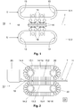
- the caterpillar casting machine 10 comprises an upper first guide rail 12.1 and a lower second guide rail 12.2. With these guide rails 12.1, 12.2 two oppositely arranged endless horizontal circulating tracks U for the caterpillar casting machine 10 are formed. Each guide rail 12.1, 12.2 has deflection areas 13 with which the straight sections of the orbits U are connected. A plurality of loose support elements 14 with cooling blocks 16 attached to them are guided along each guide rail 12.1, 12.2, in such a way that a continuous chain of support elements 14 is formed, which in a transport direction T along the Guide rails 16 are moved or transported. To illustrate the operation of the present invention are in Fig. 1 on the two guide rails 12.1, 12.2 only two support elements 14 with cooling blocks 16 attached to them are shown.
- Fig. 1 shows that a casting mold 18 is formed between the cooling blocks 16, which come into opposition in the straight sections of the circulating tracks U formed by the guide rails 12.1, 12.2.
- this casting mold 15 is a casting mold moving in the transport direction T.
- Fig. 2 shows a simplified side view of the caterpillar casting machine 10 according to the invention, in which the guide rails 12.1, 12.2 of Fig. 1 can be used.
- the caterpillar casting machine 10 comprises an upper caterpillar 14.1 and a lower caterpillar 14.2, which - as explained above - are each formed from a plurality of loose support elements 14 and cooling blocks 16 attached to them, which run along the orbits U formed by the guide rails 14 in the transport direction T. be moved.
- the upper run 14.1 has an upper run 15.1 and a lower run 15.2.
- the lower strand 14.2 has an upper strand 15.3 and a lower strand 15.4.
- the caterpillars 14.1, 14.2 are each driven by drive wheels 22 which ensure that the loose support elements 14 and the cooling blocks 16 attached to them move around the orbits U. Details regarding these drive wheels 22 are explained separately below.
- Liquid metal for example aluminum or an aluminum alloy
- a pouring nozzle 19 which is elongated and protrudes with its front end into the casting mold 18.
- a cast material 11 is produced in the form of a strip material, which - in the right image area of Fig. 2 indicated - downstream of the caterpillars 14.1, 14.2 emerges from the casting gap 18 and can then be fed to further processing (not shown).
- Cooling of the cooling blocks 16 during the casting process is ensured by cooling devices (not shown). By means of these cooling devices, a cooling medium can be applied or sprayed onto the respective cooling blocks.
- the caterpillar casting machine 10 comprises at least one actuator (not shown) with an e.g. electric, pneumatic or hydraulic actuator.
- the actuator can be controlled by a control device 21 (cf. Fig. 2 ) suitably controlled, preferably regulated, to adjust the inclination of at least one caterpillar 14.1, 14.2 relative to the other caterpillar, or to adjust the inclination of a unit formed by the two caterpillars 14.1, 14.2 relative to the horizontal.
- a drive wheel 22.1 is provided for the upper caterpillar 14.1 and for the lower caterpillar 14.2 in the deflection areas 13 of the circulating tracks U adjacent to the outlet area A, with one drive wheel 22.2 being provided in the deflection areas 13 of the circulating tracks U adjacent to the inlet area E. is.
- These drive wheels 22.1, 22.2 come into operative engagement with the support elements 14 and thus cause a circumferential movement of the support elements 14 around the orbits U.
- Both caterpillars 14.1, 14.2 are each provided with brake wheels 24, namely in the lower strand 15.2 of the upper caterpillar 14.1 adjacent to the outlet area A, and in the upper strand 15.3 of the lower caterpillar 14.2 adjacent to the outlet area A.
- the brake wheels 24 also come into operative engagement with the support elements 14, the function of these brake wheels 24 being explained below.
- a drive of the drive wheels 22.1, 22.2 in the embodiment of Fig. 3 takes place in such a way that in both caterpillars 14.1, 14.2 the speed for the drive wheels 22.1 (each adjacent to the outlet area A) is selected to be greater than that for the drive wheels 22.2 (each adjacent to the inlet area E).
- the speeds of the two brake wheels 24 are each selected to be lower than for the drive wheels 22.2.
- the mentioned speed difference between the drive wheels 22.1 and 22.2 causes both the upper run 15.1 of the upper caterpillar 14.1 and the lower run 15.4 of the lower caterpillar 14.2 to "lead" the support elements 14 with the cooling blocks 14 attached between the drive wheel 22.2 and the brake wheel 24 both in the lower run 15.2 of the upper caterpillar 14.1 and in the upper run 15.3 of the lower caterpillar 14.2 there is a “lead” of the support elements 14 with the cooling blocks 16 attached.
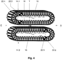
- Fig. 4 shows a further embodiment of the caterpillar casting machine 10 according to the invention in relation to an arrangement of the drive wheels 22.
- drive wheels 22.3, 22.4 are arranged for the upper caterpillar 14.1 in its straight strands 15.1, 15.2 adjacent to the inlet area E of the casting mold 18.
- For the lower caterpillar 14.2, 15.3, 15.4 are in its straight strands adjacent to the run-out area A of the mold 18 drive wheels 22.5, 22.6 are arranged.
- These drive wheels 22.3-22.6 come into operative engagement with the support elements 14, and thus cause a circumferential movement of the support elements 14 with the cooling blocks 16 attached to them around the orbits U.
- a drive of the drive wheels 22.3 -22.6 in the embodiment of Fig. 4 takes place in such a way that a higher speed is selected for the drive wheels 22.4, 22.6, which are respectively arranged in the lower strand 15.2 and 15.4 of the upper caterpillar 14.1 and the lower caterpillar 14.2, than for the drive wheels 22.3, 22.5, which are each in the upper strand 15.1 and 15.3 of the upper caterpillar 14.1 and the lower caterpillar 14.2 are arranged.
- This speed difference results in a "leading" of the support elements 14 with the cooling blocks 16 attached to them in the straight strands of the two caterpillars 14.1, 14.2 2, so that the cooling blocks 16, in the same way as with reference to the Fig. 3 already explained, are pressed against each other on the block.
- the weight causes the support elements 14 to "fall down” and thus guide them appropriately to the drive wheel 22.4 or 22.6, at which the support elements 14 begin to accelerate again.
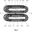
- FIG. 11 illustrates another embodiment of the track caster 10 of the present invention that is a modification of the embodiment of FIG Fig. 4 is.
- further drive wheels 22.7, 22.8 are provided for the upper caterpillar 14.1, which are arranged in the straight strands 15.1, 15.2 of the upper caterpillar 14.1 adjacent to the outlet area A of the casting mold 18.
- further drive wheels 22.9, 22.10 are provided, which are arranged in the straight runs 15.3, 15.4 of the lower caterpillar 14.2 adjacent to the inlet area E of the casting mold 18.
- Fig. 5 cause the mentioned further drive wheels 22.7-22.10 an additional movement drive for the support elements 14 with the cooling blocks 16 attached to them, and thus improve a circumferential movement of the caterpillars 14.1, 14.2 around the orbits U.
- the speeds of these drive wheels 22.7-22.10 are selected as follows: The drive wheels 22.7 and 22.9, which are arranged in the upper run 15.1 and 15.3 of the upper caterpillar 14.1 and the lower caterpillar 14.2, rotate faster than the drive wheels 22.3 and 22.5 arranged in this run.
- a "lead" is generated for the support elements 14 in the strands 15.1, 15.3, so that the cooling blocks 16 fastened to the support elements 14 are pressed against one another into a block.
- the drive wheels 22.8 and 22.10 which are arranged in the lower run 15.2 and 15.4 of the upper caterpillar 14.1 and the lower caterpillar 14.2, rotate more slowly than the drive wheels 22.4 and 22.6, which are located in these runs - in the transport direction T. seen - are arranged upstream thereof.
- the cooling blocks 16 are also pressed against one another onto a block in these lower runs 15.2, 15.4.
- the drives or drive motors assigned to the drive wheels 22.1-22.10 can be individually controlled or regulated.
- the control device 21 thus enables the speed of these individual drives or drive motors to be synchronized relative to one another.
- Fig. 6 shows, in simplified form, gears 26 with helical teeth that can be used for a drive.
- Such a helical toothing leads to an improvement in the smoothness of the drive and avoids disadvantageous vibrations during operation of the motor.
- drive wheels 22.1-22.10 which are each arranged on a front side of the caterpillars 14.1, 14.2, and additional drive wheels (each with their own drives or drive motors) each on the back of the caterpillars 14.1, 14.2 can be provided.
- additional drive wheels are located in the drawing plane in the background and therefore cannot be seen.
- pairs of drive wheels are formed which are guided coaxially from both sides into the respective caterpillars 14.1, 14.2.
- brake wheels 24 in the Fig. 3 This leads to both the embodiment of Fig. 3 as well as for those of Fig.
Landscapes
- Engineering & Computer Science (AREA)
- Mechanical Engineering (AREA)
- Continuous Casting (AREA)
- Molds, Cores, And Manufacturing Methods Thereof (AREA)
Claims (9)
- Machine de coulée du type à chenilles (10) destinée à la fabrication d'un produit de coulée (11) à partir d'un métal liquide, comprenant :deux rails de guidage (12.1, 12.2) avec lesquels on forme deux voies de circulation horizontales sans fin (U) qui sont disposées dans une position face-à-face ;une multitude d'éléments de support libres (14) contre lesquels sont appliqués des blocs de refroidissement (16) ; dans laquelle les éléments de support (14) sont guidés de manière mobile le long des voies de circulation (U) dans une direction de transport (T) d'une manière telle que, par voie de circulation (U), on forme respectivement une chaîne continue de blocs de refroidissement (16) et de cette manière une première chenille supérieure (14.1) et une deuxième chenille inférieure (14.2) ; dans laquelle, entre les blocs de refroidissement (16), qui aboutissent dans des positions opposées dans des tronçons rectilignes de la chenille supérieure, respectivement inférieure (14.1, 14.2), on réalise un moule de coulée mobile (18) pour le produit de coulée (11) ;des roues motrices avec lesquelles, contre la chenille supérieure (14.1) et contre la chenille inférieure (14.2), les éléments de support (14) qui leur sont respectivement attribués sont mis en mouvement avec les blocs de refroidissement (16) qui y sont appliqués, le long des voies de circulation (U) ; dans laquelle, on prévoit, pour la chenille supérieure (14.1) et pour la chenille inférieure (14.2), respectivement au moins deux entraînements séparés comprenant des roues motrices qui leur sont attribuées (22.1 - 22.10), qui peuvent être mises en engrènement fonctionnel avec les éléments de support (14) ; etdes moyens avec lesquels les blocs de refroidissement (16) dans les brins rectilignes (15.1 - 15.4) des chenilles (14.1, 14.2), sont poussés respectivement à bloc les uns contre les autres ;caractérisée
en ce que les entraînements qui sont destinés aux roues motrices peuvent être synchronisés librement les uns par rapport aux autres ; et en ce que, aussi bien contre la chenille supérieure (14.1) que contre la chenille inférieure (14.2) - lorsqu'on regarde dans la direction de transport (T) des éléments de support (14) - on prévoit respectivement des roues motrices (22.1 - 22.10) des deux côtés des chenilles en question ; dans laquelle un moteur d'entraînement séparé est attribué à chaque roue motrice (22.1 - 22.10) ; dans laquelle une roue motrice respective est fixée sur un arbre en bout de volant et est reliée de cette manière au moteur d'entraînement ; dans laquelle les moteurs d'entraînement qui sont destinés aux roues motrices (22.1 - 22.10) sont disposés d'une manière telle que les arbres en bout de volant, sur lesquels sont appliquées les roues motrices, ne s'étendent pas à travers les chenilles (14.1, 14.2), c'est-à-dire s'étendent sur la largeur de ces dernières. - Machine de coulée du type à chenilles (10) selon la revendication 1, caractérisée en ce que les moyens comprennent un mécanisme de commande (21) avec lequel on peut commander ou on peut régler les entraînements d'une manière telle qu'au moyen du mécanisme de commande (21) on peut régler des vitesses de rotation différentes pour les entraînements.
- Machine de coulée du type à chenilles (10) selon la revendication 1 ou 2, caractérisée en ce que les roues motrices (22.1, 22.2) sont disposées dans les zones de réorientation (13) des rails de guidage (12.1, 12.2) ; dans laquelle les moyens comprennent des roues de freinage (24) qui sont disposées dans les brins des chenilles (14.1, 14.2) qui sont disposés dans une position adjacente au module de coulée (18) et qui peuvent être amenées respectivement en engrènement opérationnel dans les éléments de support (14).
- Machine de coulée du type à chenilles (10) selon la revendication 2 ou 3, caractérisée en ce que les roues motrices (22.1, 12.2) sont disposées dans les zones de réorientation (13) des rails de guidage (22.1, 12.2) ; dans laquelle les moyens comprennent un mécanisme de déplacement avec lequel au moins une des roues motrices (22.1, 22.2) peut être déplacée en suivant un mouvement de translation dans la direction de respectivement l'autre roue motrice ou à l'écart de cette dernière.
- Machine de coulée du type à chenilles (10) selon l'une quelconque des revendications 2 à 4, caractérisée en ce que les roues motrices (22.3, 22.4) pour la chenille supérieure (141) sont disposées dans les brins rectilignes (15.1, 15.2) qui sont disposés dans une position adjacente à une zone d'entrée (E) du moule de coulée (18) ; dans laquelle les roues de coulée (22.5, 22.6) pour la chenille inférieure (14.2) sont disposées dans les brins rectilignes (15.3, 15.4) qui sont disposés dans une position adjacente à une zone de sortie (A) du moule de coulée (18) ; dans laquelle les roues motrices (22.4,22.6) sont entraînées dans les brins inférieurs respectifs (15.2, 15.4) des chenilles (14.1, 14.2) avec une vitesse de rotation supérieure à la vitesse de rotation des roues motrices (22.3, 22.5) dans les brins supérieurs respectifs (15.1, 15.3) des chenilles (14.1, 14.2).
- Machine de coulée du type à chenilles (10) selon la revendication 5, caractérisée en ce que, pour la chenille supérieure (14.1), on prévoit des roues motrices supplémentaires (22.7, 22.8) qui sont disposées dans les brins rectilignes (15.1, 15.2) de la chenille supérieure (14.1) dans une position adjacente à la zone de sortie (A) du moule de coulée (18) ; dans laquelle, pour la chenille inférieure (14.2), on prévoit des roues motrices supplémentaires (22.9, 22.10) qui sont disposées dans les brins rectilignes (15.3, 15.4) de la chenille inférieure (14.2) dans une position adjacente à la zone d'entrée (E) du moule de coulée (18).
- Machine de coulée de type à chenilles (10) selon la revendication 6, caractérisée en ce que la roue motrice (22.7), qui est disposée dans le brin supérieur (15.1) de la chenille supérieure (14.1) dans une position adjacente à la zone de sortie (A), peut être entraînée au moyen du mécanisme de commande (21) avec une vitesse de rotation supérieure à celle de la roue motrice (22.3) qui est disposée dans le brin supérieur (15.1) de la chenille supérieure (14.1) dans une position adjacente à la zone d'entrée (E) ; et en ce que la roue motrice (22.4), qui est disposée dans le brin inférieur (15.2) de la chenille supérieure (14.1) dans une position adjacente à la zone d'entrée (E), peut être entraînée, au moyen du mécanisme de commande (21) à une vitesse de rotation supérieure à celle de la roue motrice (22.8) qui est disposée dans le brin inférieur (15.2) de la chenille supérieure (14.1) dans une position adjacente à la zone de sortie (A).
- Machine de coulée du type à chenilles (10) selon la revendication 6 ou 7, caractérisée en ce que la roue motrice (22.9), qui est disposée dans le brin supérieur (15.3) de la chenille inférieure (14.2) dans une position adjacente à la zone d'entrée (E), peut être entraînée au moyen du mécanisme de commande (21) avec une vitesse de rotation supérieure à celle de la roue motrice (22.5) qui est disposée dans le brin supérieur (15.3) de la chenille inférieure (14.2) dans une position adjacente à la zone de sortie (A), et en ce que la roue motrice (22.6), qui est disposée dans le brin inférieur (15.4) de la chenille inférieure (14.2) dans une position adjacente à la zone de sortie (A), peut être entraînée au moyen du mécanisme de commande (21) avec une vitesse de rotation supérieure à celle de la roue motrice (22.10) qui est disposée dans le brin inférieur (15.4) de la chenille inférieure (14.2) dans une position adjacente à la zone d'entrée (E).
- Machine de coulée du type à chenilles (10) selon l'une quelconque des revendications précédentes, caractérisée en ce que les entraînements présentent respectivement des roues dentées (26) qui comprennent une denture hélicoïdale.
Applications Claiming Priority (2)
| Application Number | Priority Date | Filing Date | Title |
|---|---|---|---|
| DE102016223718 | 2016-11-29 | ||
| PCT/EP2017/080386 WO2018099825A1 (fr) | 2016-11-29 | 2017-11-24 | Machine de coulée à chenilles et procédé pour la fabrication d'un produit coulé à partir de métal liquide |
Publications (2)
| Publication Number | Publication Date |
|---|---|
| EP3548202A1 EP3548202A1 (fr) | 2019-10-09 |
| EP3548202B1 true EP3548202B1 (fr) | 2020-10-14 |
Family
ID=60629669
Family Applications (1)
| Application Number | Title | Priority Date | Filing Date |
|---|---|---|---|
| EP17811504.4A Active EP3548202B1 (fr) | 2016-11-29 | 2017-11-24 | Machine de coulée de chenilles pour produire un produit de coulée à partir de métal liquide |
Country Status (3)
| Country | Link |
|---|---|
| EP (1) | EP3548202B1 (fr) |
| DE (1) | DE102017221092A1 (fr) |
| WO (1) | WO2018099825A1 (fr) |
Family Cites Families (5)
| Publication number | Priority date | Publication date | Assignee | Title |
|---|---|---|---|---|
| US3835917A (en) * | 1972-11-27 | 1974-09-17 | Prolizenz Ag | Continuous casting of non-ferrous metals |
| GB2033271B (en) * | 1979-07-31 | 1982-05-06 | Webber C E | Continuous casting machine |
| US5133401A (en) * | 1991-03-25 | 1992-07-28 | Aluminum Company Of America | Continuous casting machine with mold block assemblies interlinked by elastic hinges |
| US5645122A (en) | 1994-03-30 | 1997-07-08 | Lauener Engineering, Ltd. | Block fixation and adjustment in a continuous caster |
| ES2293207T3 (es) * | 2004-01-14 | 2008-03-16 | Lamec Ag | Maquina de colada. |
-
2017
- 2017-11-24 DE DE102017221092.3A patent/DE102017221092A1/de not_active Withdrawn
- 2017-11-24 WO PCT/EP2017/080386 patent/WO2018099825A1/fr not_active Ceased
- 2017-11-24 EP EP17811504.4A patent/EP3548202B1/fr active Active
Non-Patent Citations (1)
| Title |
|---|
| None * |
Also Published As
| Publication number | Publication date |
|---|---|
| EP3548202A1 (fr) | 2019-10-09 |
| WO2018099825A1 (fr) | 2018-06-07 |
| DE102017221092A1 (de) | 2018-05-30 |
Similar Documents
| Publication | Publication Date | Title |
|---|---|---|
| DE873604C (de) | Vorrichtung zum Ausziehen und Kraeuseln von Faeden oder Fasern aus geschmolzener Glas- oder aehnlicher Masse | |
| EP0053274B1 (fr) | Procédé et dispositif pour enlever continuellement du matériau de surfaces de coulée continue par moyen mécanique | |
| DE2245983C3 (de) | Vorrichtung zur Kühlung von Walzdraht | |
| DE68903494T2 (de) | Maschine zum schneiden von granitblock- oder steinmaterialien in platten. | |
| EP0829322B1 (fr) | Cisaille à grande vitesse pour le tronçonnage de feuillard laminé | |
| EP3495086B1 (fr) | Procédé et dispositif de fabrication d'un matériau composite en forme de bande | |
| DE3313542C1 (de) | Antriebsvorrichtung fuer Giesswalzen | |
| EP0119283A1 (fr) | Procédé et dispositif de découpage d'un bloc de béton poreux à l'état encore plastique avec un fil de coupe sous tension | |
| DE2531591A1 (de) | Verfahren und einrichtung zum aendern des querschnittes von brammen | |
| EP0030013A1 (fr) | Procédé et dispositif pour découper des blocs en matière plastique | |
| EP1099502B1 (fr) | Cisaille volante pour couper des bandes métalliques | |
| DE2359464A1 (de) | Verfahren zum walzen eines kontinuierlich gegossenen, periodisch aus der kuehlkokille herausgezogenen strangs und walzwerk zur verwirklichung dieses verfahrens | |
| EP3548202A1 (fr) | Machine de coulée à chenilles et procédé pour la fabrication d'un produit coulé à partir de métal liquide | |
| DE2638629A1 (de) | Schlittenziehmaschine zum gleichfoermigen ziehen und auf-laenge-schneiden von langgestrecktem ziehmaterial | |
| DE2407917A1 (de) | Verfahren und vorrichtung zum kontinuierlichen giessen von geschmolzenem material | |
| DE3447183A1 (de) | Trennmaschine fuer kreisbogenfoermige profilstuecke oder profilringe | |
| EP3548203B1 (fr) | Méthode d'utilisation d'une machine de coulée par chaine pour couler du métal | |
| DE2657248A1 (de) | Verfahren und vorrichtung zum mehrstranggiessen | |
| DE3029990A1 (de) | Stranggiess-walzengeruest fuer mehrstranggiessanlagen zum giessen von metall, insbesondere von stahl | |
| DE3415237C1 (de) | Einrichtung zur Beeinflussung der Kühlwirkung einer Doppelbandstranggießkokille zum Vergießen von Aluminium | |
| AT397480B (de) | Walzgutschere | |
| DE102019113084A1 (de) | Verfahren zur Oberflächenbearbeitung einer Gesteins- und/oder Betonoberfläche | |
| DE72736C (de) | Verfahren und Vorrichtung zur Herstellung von Blei- oder Zinkstreifen | |
| DE2138834C3 (de) | Schnittführung, insbesondere für Zigarettenmaschinen | |
| DE2742043A1 (de) | Richtmaschine |
Legal Events
| Date | Code | Title | Description |
|---|---|---|---|
| STAA | Information on the status of an ep patent application or granted ep patent |
Free format text: STATUS: UNKNOWN |
|
| STAA | Information on the status of an ep patent application or granted ep patent |
Free format text: STATUS: THE INTERNATIONAL PUBLICATION HAS BEEN MADE |
|
| PUAI | Public reference made under article 153(3) epc to a published international application that has entered the european phase |
Free format text: ORIGINAL CODE: 0009012 |
|
| STAA | Information on the status of an ep patent application or granted ep patent |
Free format text: STATUS: REQUEST FOR EXAMINATION WAS MADE |
|
| 17P | Request for examination filed |
Effective date: 20190701 |
|
| AK | Designated contracting states |
Kind code of ref document: A1 Designated state(s): AL AT BE BG CH CY CZ DE DK EE ES FI FR GB GR HR HU IE IS IT LI LT LU LV MC MK MT NL NO PL PT RO RS SE SI SK SM TR |
|
| AX | Request for extension of the european patent |
Extension state: BA ME |
|
| DAV | Request for validation of the european patent (deleted) | ||
| DAX | Request for extension of the european patent (deleted) | ||
| GRAP | Despatch of communication of intention to grant a patent |
Free format text: ORIGINAL CODE: EPIDOSNIGR1 |
|
| STAA | Information on the status of an ep patent application or granted ep patent |
Free format text: STATUS: GRANT OF PATENT IS INTENDED |
|
| INTG | Intention to grant announced |
Effective date: 20200515 |
|
| GRAS | Grant fee paid |
Free format text: ORIGINAL CODE: EPIDOSNIGR3 |
|
| GRAA | (expected) grant |
Free format text: ORIGINAL CODE: 0009210 |
|
| STAA | Information on the status of an ep patent application or granted ep patent |
Free format text: STATUS: THE PATENT HAS BEEN GRANTED |
|
| AK | Designated contracting states |
Kind code of ref document: B1 Designated state(s): AL AT BE BG CH CY CZ DE DK EE ES FI FR GB GR HR HU IE IS IT LI LT LU LV MC MK MT NL NO PL PT RO RS SE SI SK SM TR |
|
| REG | Reference to a national code |
Ref country code: GB Ref legal event code: FG4D Free format text: NOT ENGLISH |
|
| REG | Reference to a national code |
Ref country code: AT Ref legal event code: REF Ref document number: 1323083 Country of ref document: AT Kind code of ref document: T Effective date: 20201015 Ref country code: CH Ref legal event code: EP |
|
| REG | Reference to a national code |
Ref country code: DE Ref legal event code: R096 Ref document number: 502017007787 Country of ref document: DE |
|
| REG | Reference to a national code |
Ref country code: IE Ref legal event code: FG4D Free format text: LANGUAGE OF EP DOCUMENT: GERMAN |
|
| REG | Reference to a national code |
Ref country code: CH Ref legal event code: NV Representative=s name: SCHMAUDER AND PARTNER AG PATENT- UND MARKENANW, CH |
|
| REG | Reference to a national code |
Ref country code: NL Ref legal event code: MP Effective date: 20201014 |
|
| PG25 | Lapsed in a contracting state [announced via postgrant information from national office to epo] |
Ref country code: PT Free format text: LAPSE BECAUSE OF FAILURE TO SUBMIT A TRANSLATION OF THE DESCRIPTION OR TO PAY THE FEE WITHIN THE PRESCRIBED TIME-LIMIT Effective date: 20210215 Ref country code: RS Free format text: LAPSE BECAUSE OF FAILURE TO SUBMIT A TRANSLATION OF THE DESCRIPTION OR TO PAY THE FEE WITHIN THE PRESCRIBED TIME-LIMIT Effective date: 20201014 Ref country code: FI Free format text: LAPSE BECAUSE OF FAILURE TO SUBMIT A TRANSLATION OF THE DESCRIPTION OR TO PAY THE FEE WITHIN THE PRESCRIBED TIME-LIMIT Effective date: 20201014 Ref country code: GR Free format text: LAPSE BECAUSE OF FAILURE TO SUBMIT A TRANSLATION OF THE DESCRIPTION OR TO PAY THE FEE WITHIN THE PRESCRIBED TIME-LIMIT Effective date: 20210115 Ref country code: NO Free format text: LAPSE BECAUSE OF FAILURE TO SUBMIT A TRANSLATION OF THE DESCRIPTION OR TO PAY THE FEE WITHIN THE PRESCRIBED TIME-LIMIT Effective date: 20210114 |
|
| REG | Reference to a national code |
Ref country code: LT Ref legal event code: MG4D |
|
| PG25 | Lapsed in a contracting state [announced via postgrant information from national office to epo] |
Ref country code: ES Free format text: LAPSE BECAUSE OF FAILURE TO SUBMIT A TRANSLATION OF THE DESCRIPTION OR TO PAY THE FEE WITHIN THE PRESCRIBED TIME-LIMIT Effective date: 20201014 Ref country code: BG Free format text: LAPSE BECAUSE OF FAILURE TO SUBMIT A TRANSLATION OF THE DESCRIPTION OR TO PAY THE FEE WITHIN THE PRESCRIBED TIME-LIMIT Effective date: 20210114 Ref country code: SE Free format text: LAPSE BECAUSE OF FAILURE TO SUBMIT A TRANSLATION OF THE DESCRIPTION OR TO PAY THE FEE WITHIN THE PRESCRIBED TIME-LIMIT Effective date: 20201014 Ref country code: IS Free format text: LAPSE BECAUSE OF FAILURE TO SUBMIT A TRANSLATION OF THE DESCRIPTION OR TO PAY THE FEE WITHIN THE PRESCRIBED TIME-LIMIT Effective date: 20210214 Ref country code: PL Free format text: LAPSE BECAUSE OF FAILURE TO SUBMIT A TRANSLATION OF THE DESCRIPTION OR TO PAY THE FEE WITHIN THE PRESCRIBED TIME-LIMIT Effective date: 20201014 Ref country code: LV Free format text: LAPSE BECAUSE OF FAILURE TO SUBMIT A TRANSLATION OF THE DESCRIPTION OR TO PAY THE FEE WITHIN THE PRESCRIBED TIME-LIMIT Effective date: 20201014 |
|
| PG25 | Lapsed in a contracting state [announced via postgrant information from national office to epo] |
Ref country code: NL Free format text: LAPSE BECAUSE OF FAILURE TO SUBMIT A TRANSLATION OF THE DESCRIPTION OR TO PAY THE FEE WITHIN THE PRESCRIBED TIME-LIMIT Effective date: 20201014 Ref country code: HR Free format text: LAPSE BECAUSE OF FAILURE TO SUBMIT A TRANSLATION OF THE DESCRIPTION OR TO PAY THE FEE WITHIN THE PRESCRIBED TIME-LIMIT Effective date: 20201014 |
|
| REG | Reference to a national code |
Ref country code: DE Ref legal event code: R097 Ref document number: 502017007787 Country of ref document: DE |
|
| PG25 | Lapsed in a contracting state [announced via postgrant information from national office to epo] |
Ref country code: RO Free format text: LAPSE BECAUSE OF FAILURE TO SUBMIT A TRANSLATION OF THE DESCRIPTION OR TO PAY THE FEE WITHIN THE PRESCRIBED TIME-LIMIT Effective date: 20201014 Ref country code: SK Free format text: LAPSE BECAUSE OF FAILURE TO SUBMIT A TRANSLATION OF THE DESCRIPTION OR TO PAY THE FEE WITHIN THE PRESCRIBED TIME-LIMIT Effective date: 20201014 Ref country code: SM Free format text: LAPSE BECAUSE OF FAILURE TO SUBMIT A TRANSLATION OF THE DESCRIPTION OR TO PAY THE FEE WITHIN THE PRESCRIBED TIME-LIMIT Effective date: 20201014 Ref country code: CZ Free format text: LAPSE BECAUSE OF FAILURE TO SUBMIT A TRANSLATION OF THE DESCRIPTION OR TO PAY THE FEE WITHIN THE PRESCRIBED TIME-LIMIT Effective date: 20201014 Ref country code: EE Free format text: LAPSE BECAUSE OF FAILURE TO SUBMIT A TRANSLATION OF THE DESCRIPTION OR TO PAY THE FEE WITHIN THE PRESCRIBED TIME-LIMIT Effective date: 20201014 Ref country code: LU Free format text: LAPSE BECAUSE OF NON-PAYMENT OF DUE FEES Effective date: 20201124 Ref country code: MC Free format text: LAPSE BECAUSE OF FAILURE TO SUBMIT A TRANSLATION OF THE DESCRIPTION OR TO PAY THE FEE WITHIN THE PRESCRIBED TIME-LIMIT Effective date: 20201014 Ref country code: LT Free format text: LAPSE BECAUSE OF FAILURE TO SUBMIT A TRANSLATION OF THE DESCRIPTION OR TO PAY THE FEE WITHIN THE PRESCRIBED TIME-LIMIT Effective date: 20201014 |
|
| REG | Reference to a national code |
Ref country code: BE Ref legal event code: MM Effective date: 20201130 |
|
| PLBE | No opposition filed within time limit |
Free format text: ORIGINAL CODE: 0009261 |
|
| STAA | Information on the status of an ep patent application or granted ep patent |
Free format text: STATUS: NO OPPOSITION FILED WITHIN TIME LIMIT |
|
| PG25 | Lapsed in a contracting state [announced via postgrant information from national office to epo] |
Ref country code: DK Free format text: LAPSE BECAUSE OF FAILURE TO SUBMIT A TRANSLATION OF THE DESCRIPTION OR TO PAY THE FEE WITHIN THE PRESCRIBED TIME-LIMIT Effective date: 20201014 |
|
| 26N | No opposition filed |
Effective date: 20210715 |
|
| PG25 | Lapsed in a contracting state [announced via postgrant information from national office to epo] |
Ref country code: AL Free format text: LAPSE BECAUSE OF FAILURE TO SUBMIT A TRANSLATION OF THE DESCRIPTION OR TO PAY THE FEE WITHIN THE PRESCRIBED TIME-LIMIT Effective date: 20201014 Ref country code: IE Free format text: LAPSE BECAUSE OF NON-PAYMENT OF DUE FEES Effective date: 20201124 |
|
| PG25 | Lapsed in a contracting state [announced via postgrant information from national office to epo] |
Ref country code: SI Free format text: LAPSE BECAUSE OF FAILURE TO SUBMIT A TRANSLATION OF THE DESCRIPTION OR TO PAY THE FEE WITHIN THE PRESCRIBED TIME-LIMIT Effective date: 20201014 |
|
| PG25 | Lapsed in a contracting state [announced via postgrant information from national office to epo] |
Ref country code: IS Free format text: LAPSE BECAUSE OF FAILURE TO SUBMIT A TRANSLATION OF THE DESCRIPTION OR TO PAY THE FEE WITHIN THE PRESCRIBED TIME-LIMIT Effective date: 20210214 Ref country code: TR Free format text: LAPSE BECAUSE OF FAILURE TO SUBMIT A TRANSLATION OF THE DESCRIPTION OR TO PAY THE FEE WITHIN THE PRESCRIBED TIME-LIMIT Effective date: 20201014 Ref country code: MT Free format text: LAPSE BECAUSE OF FAILURE TO SUBMIT A TRANSLATION OF THE DESCRIPTION OR TO PAY THE FEE WITHIN THE PRESCRIBED TIME-LIMIT Effective date: 20201014 Ref country code: CY Free format text: LAPSE BECAUSE OF FAILURE TO SUBMIT A TRANSLATION OF THE DESCRIPTION OR TO PAY THE FEE WITHIN THE PRESCRIBED TIME-LIMIT Effective date: 20201014 |
|
| PG25 | Lapsed in a contracting state [announced via postgrant information from national office to epo] |
Ref country code: MK Free format text: LAPSE BECAUSE OF FAILURE TO SUBMIT A TRANSLATION OF THE DESCRIPTION OR TO PAY THE FEE WITHIN THE PRESCRIBED TIME-LIMIT Effective date: 20201014 |
|
| PG25 | Lapsed in a contracting state [announced via postgrant information from national office to epo] |
Ref country code: BE Free format text: LAPSE BECAUSE OF NON-PAYMENT OF DUE FEES Effective date: 20201130 |
|
| P01 | Opt-out of the competence of the unified patent court (upc) registered |
Effective date: 20230707 |
|
| REG | Reference to a national code |
Ref country code: CH Ref legal event code: U11 Free format text: ST27 STATUS EVENT CODE: U-0-0-U10-U11 (AS PROVIDED BY THE NATIONAL OFFICE) Effective date: 20251201 |
|
| PGFP | Annual fee paid to national office [announced via postgrant information from national office to epo] |
Ref country code: DE Payment date: 20251119 Year of fee payment: 9 |
|
| PGFP | Annual fee paid to national office [announced via postgrant information from national office to epo] |
Ref country code: GB Payment date: 20251121 Year of fee payment: 9 |
|
| PGFP | Annual fee paid to national office [announced via postgrant information from national office to epo] |
Ref country code: AT Payment date: 20251120 Year of fee payment: 9 |
|
| PGFP | Annual fee paid to national office [announced via postgrant information from national office to epo] |
Ref country code: IT Payment date: 20251125 Year of fee payment: 9 |
|
| PGFP | Annual fee paid to national office [announced via postgrant information from national office to epo] |
Ref country code: FR Payment date: 20251126 Year of fee payment: 9 |
|
| PGFP | Annual fee paid to national office [announced via postgrant information from national office to epo] |
Ref country code: CH Payment date: 20251201 Year of fee payment: 9 |