EP3548656B1 - Dispositif d'étirement d'extrémités inutilisées destiné à une machine à tisser - Google Patents
Dispositif d'étirement d'extrémités inutilisées destiné à une machine à tisser Download PDFInfo
- Publication number
- EP3548656B1 EP3548656B1 EP17791097.3A EP17791097A EP3548656B1 EP 3548656 B1 EP3548656 B1 EP 3548656B1 EP 17791097 A EP17791097 A EP 17791097A EP 3548656 B1 EP3548656 B1 EP 3548656B1
- Authority
- EP
- European Patent Office
- Prior art keywords
- suction nozzle
- waste
- stretching device
- deflecting element
- end stretching
- Prior art date
- Legal status (The legal status is an assumption and is not a legal conclusion. Google has not performed a legal analysis and makes no representation as to the accuracy of the status listed.)
- Active
Links
Images




Classifications
-
- D—TEXTILES; PAPER
- D03—WEAVING
- D03D—WOVEN FABRICS; METHODS OF WEAVING; LOOMS
- D03D47/00—Looms in which bulk supply of weft does not pass through shed, e.g. shuttleless looms, gripper shuttle looms, dummy shuttle looms
- D03D47/28—Looms in which bulk supply of weft does not pass through shed, e.g. shuttleless looms, gripper shuttle looms, dummy shuttle looms wherein the weft itself is projected into the shed
- D03D47/30—Looms in which bulk supply of weft does not pass through shed, e.g. shuttleless looms, gripper shuttle looms, dummy shuttle looms wherein the weft itself is projected into the shed by gas jet
- D03D47/3066—Control or handling of the weft at or after arrival
- D03D47/308—Stretching or holding the weft
Definitions
- the invention relates to a waste end stretching device for a weaving machine and a weaving machine comprising a waste end stretching device, in particular an airjet weaving machine.
- a weft thread is inserted by means of air supplied by one or more main nozzles and successive relay nozzles provided along a weft insertion channel.
- An airjet weaving machine is shown for example in US 3,901,286 .
- the portion of an inserted weft thread extending beyond a side edge of a fabric and not woven into the fabric is referred to as waste end.
- US 3,901,286 discloses a conduit arranged below the fabric at the height of a temple provided for the woven fabric, wherein the conduit has a mouth facing towards the fabric from below.
- a portion of the weft thread remains in the main nozzle or the associated main nozzle, and the main nozzle continues to blow against the portion of the weft thread arranged inside the main nozzle. This may cause damage to the weft thread.
- the longer blowing time may result in the weft thread to untwist.
- the portion of the weft thread subjected to the longer blowing time may become "unraveled".
- the untwisted or unraveled ends of the weft thread have other properties than the remaining part of the weft thread and can cause visually perceptible weaving defects.
- CH 512 606 A shows a weft receiving and guiding block for use with an insertion device which each time brings a weft of double pick length and hairpin shape into a cloth, wherein the block is vertically moveable between a first position and a second position, and wherein the block is provided both with a suction passage and with a weft guiding passage.
- the weft guiding passage is aligned with a jet nozzle opening of a weft insertion device and bridges the space between said insertion device and the shed whereas, in the first position of the block, the said passage has a position which is staggered relative to the jet nozzle opening.
- the block is constructed as a separate part of an otherwise fixed suction mouth, wherein the weft suction passage is bending from an opening in the block side facing the shed gradually into the warp direction towards an opening in the adjacent block side, which adjacent block side is slidably engaging the open end of the suction mouth.
- the weft suction passage is communicated with both of said block sides by means of a slot.
- the long waste ends can get entangled in each other and form a tangled mess near the fabric that disturbs the following inserted weft threads. Also, there is a risk that such long waste ends jump back into a following shed, in other words re-enter the shed and be woven in between warp threads.
- a waste end stretching device for a weaving machine comprising a suction nozzle adapted to be arranged in the path of a waste end of an inserted weft thread projecting beyond an edge of a woven fabric, wherein the suction nozzle is adapted for applying a suction force along a longitudinal direction of the suction nozzle, wherein the suction nozzle is adapted for being attached to the weaving machine such that the longitudinal direction of the suction nozzle extends in parallel to the weft insertion direction, wherein the suction nozzle is provided with a lateral suction slit extending along the longitudinal direction of the suction nozzle for sucking waste ends into the suction nozzle and with an opening provided at a first end of the suction nozzle facing the edge of the woven fabric for conveying waste ends held in the suction nozzle in a direction perpendicular to the longitudinal direction of the suction nozzle, and wherein a deflecting element is provided between the opening and the edge of the woven
- first end An end of the suction nozzle facing the edge of the woven fabric is referred to as first end.
- a wall at that first end is referred to as first end wall.
- Leading ends or waste ends of inserted weft threads are sucked into the suction nozzle via the lateral suction slit.
- the waste ends Prior to being cut-off from the fabric, the waste ends are moved together with the fabric in a fabric pull-off direction, wherein generally the movement path of the fabric is not a linear path.
- the fabric is guided along a temple and in some cases in addition along guide rollers.
- the opening is shielded to deflect a portion of the waste ends held in the suction nozzle and extending between the suction nozzle and the edge of the fabric radially away from the opening, such that waste ends held in the suction nozzle are deflected in their path between the edge of the woven fabric and the opening, thereby avoiding that the fabric or if applicable a waste band is drawn into the suction nozzle.
- the waste ends in one embodiment leave the suction nozzle via the opening after the fabric has been conveyed over a defined distance. In other embodiments, the waste ends are cut off and removed via a second end provided opposite the first end of the suction nozzle.
- the waste ends are guided along a lower part of the opening.
- the weaving machine may comprise a temple for expanding the woven fabric. Therefore, in preferred embodiments, the deflecting element projects at least with its lower border beyond the opening for deflecting waste ends held in the suction nozzle in their path between the edge of the woven fabric and the opening.
- the deflecting element is formed integrally with a body of the suction nozzle.
- the deflecting element and the body of the suction nozzle are formed as separate members, wherein the deflecting element is positioned with respect to the body of the suction nozzle such that a gap is provided between a first end wall of the body of the suction nozzle and the deflecting element, wherein the size of the gap is chosen large enough to avoid waste ends being caught between the first end wall of the body of the suction nozzle and the deflecting element.
- the size or width of the gap is chosen suitably by the person skilled in the art depending on the properties of the material to be woven. In preferred embodiments, the width of the gap is between about 2 mm and about 4 mm.
- the first end wall of the body of the suction nozzle is stepped such that a lower part of the first end wall that is arranged below the lateral suction slit is positioned further away from the deflecting element than an upper part of the first end wall. Due to the deflection of the waste ends by means of the deflecting element, the waste ends are guided along the edge of the opening at the lower part of the first end wall. By means of the step, a sufficient free space for guiding the waste ends is provided.
- an opening is provided that extends in a direction perpendicular to the longitudinal direction of the suction nozzle.
- the opening and the deflecting element have complementary ring-shaped, circular or semi-circular cross sections.
- the fabric is deflected by means of the temple.
- the deflecting element in one embodiment is attached directly to a frame of the weaving machine.
- the deflecting element is attached to the body of the suction nozzle.
- the deflecting element is attached to the first end wall of the body of the suction nozzle in an area above the opening.
- the upper part of the first end wall of the body of the suction nozzle is provided with a fastening projection, which fastening projection is delimiting an interior channel of the suction nozzle towards the first end, wherein the deflecting element is attached to the fastening projection.
- the waste end stretching device further comprises a mounting body, wherein the suction nozzle is attached to or is formed integrally with the mounting body, and which mounting body is adapted to be attached adjustable in position to a frame of the weaving machine.
- the position is for example only adjustable in the longitudinal direction of the suction nozzle for adjusting the position of the waste end stretching device for different fabric widths and/or different waste end lengths.
- the waste end stretching device in one embodiment further comprises a ring-jet device.
- the ring-jet device is attached to the mounting body and/or the suction nozzle and, hence, displaceable together with the suction nozzle.
- the waste ends are tucked into the fabric.
- the waste ends are not tucked in.
- the weaving machine in one embodiment is provided with catching threads or waste warp threads for forming a waste band and thereby keeping the inserted weft threads stretched.
- a temple is provided having a length that exceeds the width of the fabric.
- the waste end stretching device comprises a guide element for guiding the catching threads, wherein the guide element is positioned between the deflecting element and the edge of the woven fabric, for example at a distance from the temple.
- the guide element is attached to the frame of the weaving machine between the deflecting element and the edge of the woven fabric, which edge for example is guided by means of a temple.
- the deflecting element is formed integrally or as a structural unit with the guide element.
- the guide element in one embodiment is provided with a groove for maintaining the waste band in parallel to the edge of the fabric.
- the guide element comprises a cone-shaped, double-cone-shaped, diabolo-shaped or hourglass-shaped intermediate element arranged adjacent to the deflecting element, wherein the intermediate element comprises at least a cone-shaped first part having an increasing diameter in a direction away from the deflecting element, and wherein the smallest diameter of the first part is smaller than the diameter of the deflecting element.
- the waste band is guided in parallel to the edge of the fabric by means of the intermediate element together with the deflecting element.
- the intermediate element further comprises a cone-shaped second part having a decreasing diameter in a direction away from the deflecting element, which second part is arranged between the deflecting element and the first part.
- a cone-shaped second part having a decreasing diameter in a direction away from the deflecting element, which second part is arranged between the deflecting element and the first part.
- such an intermediate element comprising two cone-shaped parts is referred to as a double-cone shaped, diabolo-shaped or hourglass-shaped intermediate element.
- the first and second cone-shaped part in one embodiment differ in length and/or angle of aperture and/or the first and the second part both have the shape of a truncated cone.
- the intermediate element is made of a material having a small coefficient of friction when used with the weft threads, such that the waste band is conveyed smoothly along the intermediate element.
- the guide element further comprises a ring arranged adjacent to the intermediate element at a side away from the deflecting element, wherein the ring is mounted rotatably with respect to the intermediate element about an axis parallel to the weft insertion direction.
- the ring is adapted to be rotated due to the contact with the weft threads conveyed along the guide element.
- the ring preferably is made of a material having a higher coefficient of friction when used with the weft threads than the intermediate element.
- the ring is arranged slightly eccentrically with respect to the intermediate element, wherein the ring preferably has a diameter that is slightly larger than the largest diameter of the intermediate element, such that the weft threads contact the ring and not the intermediate element.
- the lateral suction slit of the suction nozzle is confined by a lower lip and an upper lip, wherein the waste end stretching device is adapted to be mounted to the weaving machine with the lateral suction slit extending close to and in parallel to a support bar of a fabric support of the weaving machine, wherein the lower lip is arranged at least essentially at the height of the support bar for guiding waste ends via the support bar and the lower lip into the suction nozzle.
- a weaving machine comprising a temple along which temple a fabric is guided and a waste end stretching device
- the waste end stretching device comprises a suction nozzle adapted for applying a suction force along a longitudinal direction of the suction nozzle, wherein the suction nozzle is arranged stationary on the weaving machine at an extension of the temple in an axial direction of the temple and with the longitudinal direction of the suction nozzle extending in parallel to the weft insertion direction.
- the waste end stretching device is arranged on the weaving machine such that the longitudinal direction of the suction nozzle is arranged coaxially with or in parallel to the axial direction of the temple.
- a use of a waste end stretching device in a weaving machine comprising a temple along which temple a fabric is guided
- the waste end stretching device comprises a suction nozzle adapted for applying a suction force along the longitudinal direction of the suction nozzle, wherein the suction nozzle is arranged stationary on the weaving machine at an extension of the temple in an axial direction of the temple and with the longitudinal direction of the suction nozzle extending in parallel to the weft insertion direction.
- the waste end stretching device when used with the weaving machine is arranged such that the longitudinal direction of the suction nozzle is arranged coaxially with or in parallel to the axial direction of the temple.
- FIGS. 1 and 2 are perspective views of a waste end stretching device 30 from the front and the back, respectively.
- the waste end stretching device 30 shown in FIGS. 1 and 2 comprises a mounting body 31, a suction nozzle 32, a guide element 40 with a deflecting element 41 attached to the body of the suction nozzle 32 at its first end 58, and a ring-jet device 33 attached to the mounting body 31 at a second end 59 of the suction nozzle 32.
- an end of the suction nozzle 32 which in use is arranged to face an edge of a woven fabric is referred to as first end 58.
- An opposite end of the suction nozzle 32 is referred to as second end 59.
- a wall at the first end 58 is referred to as first end wall 46.
- the suction nozzle 32 has a lateral suction slit 34 extending along the longitudinal direction 52 of the suction nozzle 32 for sucking leading ends or waste ends of inserted weft threads (not shown) into the suction nozzle 32.
- the suction nozzle 32 further comprises an opening 35 provided at its first end 58. The opening 35 at the first end 58 allows the waste ends to move in a direction perpendicular to the longitudinal direction 52 of the suction nozzle 32 of the waste end stretching device 30 while the waste ends are held in the suction nozzle 32 and are stretched by the suction force applied.
- the opening 35 is shielded by means of the deflecting element 41 such that waste ends of inserted weft threads (not shown in FIGS. 1 and 2 ), which are held in the suction nozzle 32 are deflected in their path between the edge of the woven fabric and the opening 35.
- the opening 35 is provided with a ring-shaped cross section and the deflecting element 41 is provided with a circular cross section, wherein the diameter of the deflecting element 41 is larger than the diameter of the opening 35.
- the deflecting element 41 projects at least with its lower border 47 beyond the opening 35 for deflecting waste ends held in the suction nozzle 32 in their path between the edge of the woven fabric 3 and the opening 35.
- a suction force along a longitudinal direction 52 of the suction nozzle 32 is applied by means of the ring-jet device 33 having a nipple 36 for an air supply.
- compressed air is supplied to the ring-jet device 33 via the nipple 36 in a pulsating manner, in particular in a not continuous manner, so that the waste ends can be sucked easily into the suction nozzle 32, and can be moved easily along the opening 35.
- An interior channel 49 of the suction nozzle 32 in the embodiment shown has an at least essentially circular cross section.
- the suction nozzle 32 is attachable to a weaving machine 11 (see FIGS. 3 to 7 ) by means of two bolts 37, wherein the position is adjustable or settable in a direction parallel to the weft insertion direction.
- a support 22 comprising two support bolts 26 is provided, which is attached fixed in position to a frame 2 (see FIGS. 3 to 7 ) of the weaving machine 11, wherein the mounting body 31 is attached settable in position to the support 22 by means of the two bolts 37.
- the guide element 40 shown is provided (seen in the longitudinal direction 52) with the deflecting element 41, an intermediate element 42, and a ring 43.
- the intermediate element 42 shown has a double-cone shape with a cone-shaped first part having an increasing diameter in a direction away from the first end wall 46 and a cone-shaped second part arranged between the first part and the deflecting element 41 having a decreasing diameter in a direction away from the first end wall 46.
- the second part is considerably shorter than the first part, for example the length of the second part is approximately a third of the length of the first part.
- the deflecting element 41 and the intermediate element 42 are for example formed integrally from a material applying only small frictional forces on the waste ends or a waste band conveyed along the guide element 40.
- the ring 43 is formed separately and is mounted rotatably to the intermediate element 42 and/or the body of the suction nozzle 32 by means of a bolt 45.
- the ring 43 is made of rubber applying a higher frictional force on the waste ends than the remainder of the guide element 40.
- the diameter of the ring 43 in the embodiment shown is slightly larger than the largest diameter of the intermediate element 42.
- the ring 43 in the embodiment shown is arranged slightly eccentrically with respect to the intermediate element 42, and extends more to the vicinity of the lower part for guiding the weft threads.
- the diameter of the deflecting element 41 is larger than the smallest diameter of the intermediate element 42.
- the diameter of the deflecting element 41 is at least essentially equal to the largest diameter of the intermediate element 42.
- the deflecting element 41 is provided at the first end 58 of the body of the suction nozzle 32.
- first end wall 46 of the body of the suction nozzle 32 arranged below the lateral suction slit 34 is referred to as lower part 50 of the first end wall 46.
- upper part 51 of the first end wall 46 is referred to as upper part 51 of the first end wall 46.
- the upper part 51 of the first end wall 46 is provided with a fastening projection 44, which fastening projection 44 is delimiting the interior channel 49 of the suction nozzle 32 towards the first end 58.
- the guide element 40 is attached to the fastening projection 44.
- the first end wall 46 of the body of the suction nozzle 32 is stepped such that the lower part 50 of the first end wall 46 is positioned further away from the deflecting element 41 than the upper part 51 of the first end wall 46.
- a sufficient free space for the waste ends held in the suction nozzle 32 is provided between the lower part 50 of the first end wall 46 and the deflecting element 41 below the opening 35.
- the deflecting element 41 is attached in such manner that a small gap 48 remains also between the upper part 51 of the first end wall 46 and the deflecting element 41 for avoiding weft threads being caught between the body of the suction nozzle 32 and the deflecting element 41.
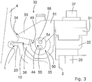
- FIG. 3 is a cross view of the waste end stretching device 30 of FIGS. 1 and 2 attached to a weaving machine having a fabric support 1 with a support bar 20 extending in a beat-up direction into a channel of a reed 4, wherein only the suction nozzle 32 is shown and, for the sake of clarity, the deflecting element 41 is not shown.
- the fastening projection 44 is protruding from the upper part 51 of the first end wall 46, delimiting the interior channel 49 of the suction nozzle 32 towards the first end 58.
- the opening 35 thus formed has essentially a ring shape, in other words the opening 35 is formed by a clear span between the interior channel 49 and the fastening projection 44.
- the guide element 40 is attached to the intermediate element 42 by means of a bolt 45, such that the ring 43 of the guide element 40 remains rotatably with respect to the intermediate element 42.
- the deflecting element 41 and the intermediate element 42 which form one assembly, are stationary attached to the suction nozzle 32 by a bolt 57 (shown in FIG. 4 ).
- the bolt 57 extends through the opening 54 (shown in FIG. 3 ) of the fastening projection 44, and can be tightened by a tool that in use extends through the suction nozzle 32.
- a pen 55 protruding from an end surface 56 of the fastening projection 44 is provided and can cooperate with an opening (not shown) in the deflecting element 41 and/or the intermediate element 42.
- the deflecting element 41 is clamped against the end surface 56.
- the lateral suction slit 34 is confined by a lower lip 38 and an upper lip 39.
- the waste end stretching device 30 is mounted to the frame 2 of the weaving machine with the lateral suction slit 34 extending in parallel to the support bar 20 of the fabric support 1, wherein the lower lip 38 is arranged at least essentially at the height of the support bar 20 of the fabric support 1 to guide waste ends via the support bar 20 and the lateral suction slit 34 into the suction nozzle 32.
- FIG. 8 schematically shows a cross view of a weaving machine 11 with a fabric support 1 and a temple 23.
- the fabric support 1 shown is attached to a frame 2 of a weaving machine in order to support a fabric 3.
- the fabric support 1 extends at least across the width of the fabric 3, for example across a length in the order of magnitude of several meters.
- a reed 4, a sley 5, a clamping bar 6, sley legs 7 and a sley shaft 8 are shown.
- the reed 4 is clamped to the sley 5 by means of the clamping bar 6 and bolts 25.
- a guide roller 24 for the fabric 3 is provided downstream of the temple 23 near the fabric support 1. For a weft insertion, the weft thread is blown into a shed by means of a main blowing device (not shown) and a plurality of relay blowers 9, which are attached to the sley 5 in a known manner.
- the fabric support 1 comprises at least one profiled support bar 20, supported by a plurality of supporting elements 10, which are attached to the frame 2 by means of screw elements 21.
- the profiled support bar 20 is attached in such manner that its end facing the reed 4 extends into a channel of the reed 4 upon beat-up.
- the supporting element 10 is provided with a collar 27 which allows attaching the supporting element 10 with high accuracy to the frame 2.
- Such a fabric support 1 is shown for example in US 7,770,605 B2 , the content of which is herewith incorporated by reference.
- the waste end stretching device 30 and its use in a weaving machine will be described in more detail with reference to FIGS. 5 to 7 further below.
- FIGS. 5 , 6 and 7 schematically show the weaving machine 11 with the fabric support 1, the temple 23 and the waste end stretching device 30 shown in FIGS. 1 and 2 in a perspective view from the back of the weaving machine and from above, in a perspective view from the back and in a view from above, respectively.
- the lateral suction slit 34 is confined by the lower lip 38 and the upper lip 39.
- the waste end stretching device 30 is mounted to the frame 2 of the weaving machine with the opening 35 facing an edge of the fabric 3 and, thus, towards the temple 23 and the lateral suction slit 34 extending in parallel to the weft insertion direction 29, in other words in parallel to a beat-up line of the fabric 3, wherein the lower lip 38 is arranged at least essentially at the height of the support bar 20 of the fabric support 1 to guide waste ends via the support bar 20 and the lateral suction slit 34 into the suction nozzle 32.
- the suction nozzle 32 is arranged stationary on the weaving machine 11, and at an extension of the temple 23 in an axial direction 53 of the temple 23 and with the longitudinal direction 52 of the suction nozzle 32 extending in parallel to the weft insertion direction 29.
- catching threads 12 are provided for catching the waste ends of the inserted weft threads 13.
- the fabric band woven by means of the catching threads 12 is referred to as waste band 18.
- no catching threads are provided and the waste ends are tucked in, for example using a device as described in WO 2015/189033 A1 and/or EP 2176455 B1 , the content of which is herewith incorporated by reference.
- a separate auxiliary reed 14 (see FIGS. 4 and 6 ) is provided for the catching threads 12, which is attached to the sley 5.
- Weft thread detectors 15, 16 are provided at the arrival end of the reed 4 and the auxiliary reed 14.
- the waste band 18 and the waste ends are cut off from the fabric 3 by means of a schematically shown cutting device 17.
- a tensioning device 19 comprising nozzles, for example two nozzles, is provided at the auxiliary reed 14 for tensioning already inserted weft threads.
- Such a tensioning device 19 is described for example in WO 2015/177155 A1 , the content of which is herewith incorporated by reference.
- the guide element 40 is positioned at a distance from the temple 23, wherein the position of the temple 23 is chosen to at least essentially match the width of the fabric 3.
- the waste band 18 is guided along the intermediate element 42 of the guide element 40, wherein the deflecting element 41 having a larger diameter than the suction nozzle 32 mechanically and fluid mechanically hinders the waste band 18 from being sucked into the suction nozzle 32.
- the rotatably mounted ring 43 of the guide element 40 has a slightly larger diameter than the largest diameter of the intermediate element 42. Hence, the ring 43 will contact the weft threads extending between the temple 23 and the suction nozzle 32 via the guide element 40, and the weft threads are guided upon the movement of the fabric 3 along the ring 43.
- the weft threads are inserted and tensioned by the tensioning device 19, then beaten up while the leading end or waste end of the inserted weft thread extending beyond the catching threads 12 is sucked into the suction nozzle 32 via the lateral suction slit 34.
- the waste ends remain stretched by means of the waste end stretching device 30 while they are conveyed with the fabric 3 in the pull-off direction, wherein the waste ends are moved along the opening 35.
- the waste band 18 is guided by means of the intermediate element 42.
- the deflecting element 41 hinders the waste band 18 from being sucked into the suction nozzle 32.
- the waste ends will eventually be removed from the suction nozzle 32 via the opening 35. In other embodiments, the waste ends are cut-off and removed via the second end 59 of the suction nozzle 32.
- the attachment of the suction nozzle 32 in a weaving machine is not limited to the use of the support 22 and the mounting body 31, but to this end according to an alternative fastening elements can be used allowing for a setting of the position of the suction nozzle 32 with respect to the weaving machine.
- waste end stretching device the weaving machine and the use of a waste end stretching device according to the invention are not limited to the embodiments described by way of example and illustrated in the drawings. Alternatives and combinations of the described and illustrated embodiments that fall under the claims are also possible.
Landscapes
- Engineering & Computer Science (AREA)
- Textile Engineering (AREA)
- Looms (AREA)
- Auxiliary Weaving Apparatuses, Weavers' Tools, And Shuttles (AREA)
Claims (15)
- Dispositif d'étirage d'extrémité de déchets pour une machine à tisser comprenant une buse d'aspiration (32) adaptée pour être disposée dans la voie d'une extrémité de déchets d'un fil de trame (13) inséré faisant saillie au-delà d'un bord d'un tissu tissé (3), dans lequel la buse d'aspiration (32) est adaptée pour appliquer une force d'aspiration le long d'une direction longitudinale (52) de la buse d'aspiration (32), dans lequel la buse d'aspiration (32) est adaptée pour être fixée à la machine à tisser (11) de telle sorte que la direction longitudinale (52) de la buse d'aspiration (32) s'étend parallèlement à la direction d'insertion de trame (29), caractérisé en ce que la buse d'aspiration (32) est prévue d'une fente d'aspiration latérale (34) s'étendant le long de la direction longitudinale (52) de la buse d'aspiration (32) pour aspirer d'extrémités de déchets dans la buse d'aspiration (32) et avec une ouverture (35) disposée sur une première extrémité (58) de la buse d'aspiration (32) faisant face au bord du tissu tissé (3) pour transporter d'extrémités de déchets maintenues dans la buse d'aspiration (32) dans une direction perpendiculaire à la direction longitudinale (52) de la buse d'aspiration (32), et dans lequel un élément de renvoi (41) est disposé entre l'ouverture (35) et le bord du tissu tissé (3), lequel élément de renvoi (41) fait saillie au moins partiellement au-delà de l'ouverture (35) pour dévier d'extrémités de déchets maintenues dans la buse d'aspiration (32) dans leur voie entre le bord du tissu tissé (3) et l'ouverture (35).
- Dispositif d'étirage d'extrémité de déchets selon la revendication 1, caractérisé en ce que l'élément de renvoi (41) fait saillie au moins avec sa bordure inférieure (47) au-delà de l'ouverture (35) pour dévier d'extrémités de déchets maintenues dans la buse d'aspiration (32) dans leur voie entre le bord du tissu tissé (3) et l'ouverture (35).
- Dispositif d'étirage d'extrémité de déchets selon la revendication 1 ou 2, caractérisé en ce que l'élément de renvoi (41) et un corps de la buse d'aspiration (32) sont formés comme des membres séparés, dans lequel l'élément de renvoi (41) est positionné par rapport au corps de la buse d'aspiration (32) de telle sorte qu'un espace (48) est prévu entre une première paroi d'extrémité (46) du corps de la buse d'aspiration (32) et l'élément de renvoi (41), dans lequel la largeur de l'espace (48) est choisie suffisamment grande pour éviter que d'extrémités de déchets sont capturées entre la première paroi d'extrémité (46) du corps de la buse d'aspiration (32) et l'élément de renvoi (41).
- Dispositif d'étirage d'extrémité de déchets selon la revendication 1, 2 ou 3, caractérisé en ce qu'une première paroi d'extrémité (46) d'un corps de la buse d'aspiration (32) est étagée de telle sorte qu'une partie inférieure (50) de la première paroi d'extrémité (46) au-dessous de la fente d'aspiration latérale (34) est positionnée plus loin de l'élément de renvoi (41) qu'une partie supérieure (51) de la première paroi d'extrémité (46).
- Dispositif d'étirage d'extrémité de déchets selon la revendication 3 ou 4, caractérisé en ce qu'une partie supérieure (51) de la première paroi d'extrémité (46) du corps de la buse d'aspiration (32) est prévue d'une saillie de fixation (44), laquelle saillie de fixation (44) est délimitée par un canal intérieur (49) de la buse d'aspiration (32) vers la première extrémité (58), dans lequel l'élément de renvoi (41) est fixé à la saillie de fixation (44).
- Dispositif d'étirage d'extrémité de déchets selon l'une quelconque des revendications 1 à 5, caractérisé en ce que l'ouverture (35) et l'élément de renvoi (41) ont des sections complémentaires de forme annulaire, circulaires ou semi-circulaires.
- Dispositif d'étirage d'extrémité de déchets selon l'une quelconque des revendications 1 à 6, caractérisé en ce que le dispositif d'étirage d'extrémité de déchets (30) comprend en outre un corps de montage (31), dans lequel la buse d'aspiration (32) est fixée au ou est formée intégralement avec le corps de montage (31), et lequel corps de montage (31) est adapté pour être fixé de manière réglable en position à un châssis (2) de la machine à tisser (11).
- Dispositif d'étirage d'extrémité de déchets selon l'une quelconque des revendications 1 à 7, caractérisé en ce que le dispositif d'étirage d'extrémité de déchets (30) comprend un corps de montage (31) et comprend en outre un dispositif à jet annulaire (33) pour fournir une force d'aspiration, dans lequel le dispositif à jet annulaire (33) est fixé de préférence au corps de montage (31) et/ou à la buse d'aspiration (32).
- Dispositif d'étirage d'extrémité de déchets selon l'une quelconque des revendications 1 à 8, caractérisé en ce qu'un élément de guidage (40) pour guider des fils auxiliaires (12) est prévu, dans lequel l'élément de guidage (40) est positionné entre l'élément de renvoi (41) et le bord du tissu tissé (3).
- Dispositif d'étirage d'extrémité de déchets selon la revendication 9, caractérisé en ce que l'élément de renvoi (41) est formé intégralement ou comme une unité structurelle avec l'élément de guidage (40).
- Dispositif d'étirage d'extrémité de déchets selon la revendication 9 ou 10, caractérisé en ce que l'élément de guidage (40) comprend un élément intermédiaire (42) en forme de cône, en forme de cône double ou en forme de sablier disposé adjacent à l'élément de renvoi (41), dans lequel l'élément intermédiaire (42) comprend au moins une première partie en forme de cône ayant un diamètre croissant dans une direction s'éloignant de l'élément de renvoi (41), et dans lequel le plus petit diamètre de la première partie est inférieur au diamètre de l'élément de renvoi (41).
- Dispositif d'étirage d'extrémité de déchets selon la revendication 11, caractérisé en ce que l'élément de guidage (40) comprend en outre un anneau (43) disposé adjacente à l'élément intermédiaire (42) à un côté loin de l'élément de renvoi (41), dans lequel l'anneau (43) est monté rotatif par rapport à l'élément intermédiaire (42) autour d'un axe parallèle à la direction d'insertion de trame (29).
- Machine à tisser comprenant un templet (23) le long duquel templet (23) un tissu (3) est guidé et un dispositif d'étirage d'extrémité de déchets (30) selon l'une quelconque des revendications 1 à 12, dans laquelle le dispositif d'étirage d'extrémité de déchets (30) comprend une buse d'aspiration (32) adaptée pour appliquer une force d'aspiration le long d'une direction longitudinale (52) de la buse d'aspiration (32), dans laquelle la buse d'aspiration (32) est disposée stationnaire sur la machine à tisser (11) au niveau d'une extension du templet (23) dans une direction axiale (53) du templet (23) et avec la direction longitudinale (52) de la buse d'aspiration (32) s'étendant parallèlement à la direction d'insertion de trame (29).
- Machine à tisser selon la revendication 13, caractérisée en ce que la fente d'aspiration latérale (34) de la buse d'aspiration (32) est confinée par une lèvre inférieure (38) et une lèvre supérieure (39), dans laquelle le dispositif d'étirage d'extrémité de déchets (30) est monté à la machine à tisser (11) avec la fente d'aspiration latérale (34) s'étendantà proximité de et parallèlement à une barre de support (20) d'un support de tissu (1) de la machine à tisser (11), de sorte que la lèvre inférieure (38) est disposée au moins essentiellement à l'hauteur de la barre de support (20) pour guider d'extrémités de déchets par la barre de support (20) et la lèvre inférieure (38) dans la buse d'aspiration (32).
- Utilisation d'un dispositif d'étirage d'extrémité de déchets selon l'une quelconque des revendications 1 à 12 dans une machine à tisser (11) comprenant un templet (23) le long duquel templet (23) un tissu (3) est guidé, dans laquelle le dispositif d'étirement d'extrémité de déchets (30) comprend une buse d'aspiration (32) adaptée pour appliquer une force d'aspiration le long de la direction longitudinale (52) de la buse d'aspiration (32), dans laquelle la buse d'aspiration (32) est disposée stationnaire sur la machine à tisser (11) au niveau d'une extension du templet (23) dans une direction axiale (53) du templet (23) et avec la direction longitudinale (52) de la buse d'aspiration (32) s'étendant parallèlement à la direction d'insertion de trame (29).
Applications Claiming Priority (2)
| Application Number | Priority Date | Filing Date | Title |
|---|---|---|---|
| BE2016/0178A BE1024755B1 (nl) | 2016-11-29 | 2016-11-29 | Afvaleinde-strekinrichting voor een weefmachine |
| PCT/EP2017/077638 WO2018099662A1 (fr) | 2016-11-29 | 2017-10-27 | Dispositif d'étirement d'extrémités inutilisées destiné à une machine à tisser |
Publications (2)
| Publication Number | Publication Date |
|---|---|
| EP3548656A1 EP3548656A1 (fr) | 2019-10-09 |
| EP3548656B1 true EP3548656B1 (fr) | 2020-12-16 |
Family
ID=57544144
Family Applications (1)
| Application Number | Title | Priority Date | Filing Date |
|---|---|---|---|
| EP17791097.3A Active EP3548656B1 (fr) | 2016-11-29 | 2017-10-27 | Dispositif d'étirement d'extrémités inutilisées destiné à une machine à tisser |
Country Status (4)
| Country | Link |
|---|---|
| EP (1) | EP3548656B1 (fr) |
| CN (1) | CN109983166B (fr) |
| BE (1) | BE1024755B1 (fr) |
| WO (1) | WO2018099662A1 (fr) |
Families Citing this family (2)
| Publication number | Priority date | Publication date | Assignee | Title |
|---|---|---|---|---|
| CN110735217B (zh) * | 2019-11-21 | 2020-12-22 | 福建宇邦纺织科技有限公司 | 一种喷气织机织造化纤长丝织物捕纬装置 |
| CN110886043A (zh) * | 2019-12-26 | 2020-03-17 | 鲁丰织染有限公司 | 降低喷气织机废边纱长度的拉伸辅喷系统 |
Family Cites Families (17)
| Publication number | Priority date | Publication date | Assignee | Title |
|---|---|---|---|---|
| BE757859A (nl) * | 1969-10-22 | 1971-04-01 | Strake Maschf Nv | Weefmachine |
| NL7108526A (fr) * | 1971-06-21 | 1972-12-27 | ||
| US3901286A (en) | 1973-08-20 | 1975-08-26 | Rueti Te Strake Bv | Weft tensioning and cutting means |
| CH594089A5 (fr) * | 1976-01-27 | 1977-12-30 | Rueti Ag Maschf | |
| BE1000989A3 (nl) * | 1987-10-09 | 1989-05-30 | Picanol Nv | Inrichting voor het strekken van een inslagdraad bij weefmachines. |
| IT216529Z2 (it) * | 1989-04-21 | 1991-09-16 | Somet Soc Mec Tessile | Dispositivo aspiratore del filo di trama per telaio di tessitura ad aria. |
| JPH09256245A (ja) * | 1996-03-22 | 1997-09-30 | Toyota Autom Loom Works Ltd | ジェットルームにおける緯糸張力付与装置 |
| KR100250384B1 (ko) * | 1997-11-13 | 2000-04-01 | 정원기 | 워터제트직기의 위사절단사 처리장치 |
| CN2661725Y (zh) * | 2003-12-08 | 2004-12-08 | 河北保定依棉集团有限公司 | 一种用于喷气织机的废边纱导轨 |
| BE1017274A6 (nl) | 2006-09-13 | 2008-05-06 | Picanol Nv | Weefselsteun voor een weefmachine. |
| BE1017684A3 (nl) | 2007-07-12 | 2009-03-03 | Picanol Nv | Werkwijze voor het inleggen van een einde van een inslagdraad in een kant van een weefsel en pneumatische kanteninlegger. |
| KR101043654B1 (ko) * | 2008-09-09 | 2011-06-22 | 젯트기연 주식회사 | 워터젯트직기의 위사선단부 처리장치 |
| JP5369915B2 (ja) * | 2009-06-11 | 2013-12-18 | 株式会社豊田自動織機 | エアジェット織機における緯糸張力付与装置 |
| EP2348144A1 (fr) * | 2010-01-26 | 2011-07-27 | ITEMA (Switzerland) Ltd. | Dispositif d'étirement pneumatique du fil de trame pour métiers à tisser à jet d'air, avec tête de déviation de trame agencée dans le canal de lancement du peigne |
| BE1021879B1 (nl) | 2014-05-22 | 2016-01-25 | Picanol | Strekinrichting voor een inslagdraad |
| BE1022146B1 (nl) | 2014-06-13 | 2016-02-19 | Picanol | Zelfkantvormingsinrichting voor een inslagdraad |
| JP6119715B2 (ja) * | 2014-10-27 | 2017-04-26 | 株式会社豊田自動織機 | エアジェット織機における緯糸張力付与装置 |
-
2016
- 2016-11-29 BE BE2016/0178A patent/BE1024755B1/nl not_active IP Right Cessation
-
2017
- 2017-10-27 WO PCT/EP2017/077638 patent/WO2018099662A1/fr not_active Ceased
- 2017-10-27 CN CN201780073860.XA patent/CN109983166B/zh active Active
- 2017-10-27 EP EP17791097.3A patent/EP3548656B1/fr active Active
Non-Patent Citations (1)
| Title |
|---|
| None * |
Also Published As
| Publication number | Publication date |
|---|---|
| CN109983166A (zh) | 2019-07-05 |
| BE1024755A1 (nl) | 2018-06-20 |
| EP3548656A1 (fr) | 2019-10-09 |
| WO2018099662A1 (fr) | 2018-06-07 |
| CN109983166B (zh) | 2020-12-11 |
| BE1024755B1 (nl) | 2018-06-27 |
Similar Documents
| Publication | Publication Date | Title |
|---|---|---|
| EP2449158B1 (fr) | Dispositif et procédé de saisie et d étirage des fils de trame dans une machine à tisser | |
| EP3548656B1 (fr) | Dispositif d'étirement d'extrémités inutilisées destiné à une machine à tisser | |
| FR2497841A1 (fr) | Metier a tisser a tuyeres | |
| JP6119715B2 (ja) | エアジェット織機における緯糸張力付与装置 | |
| CN104220659B (zh) | 捕捉和拉伸纬纱的装置、织机、捕捉和拉伸纬纱的方法 | |
| EP3146101B1 (fr) | Dispositif d'étirage pour un fil de trame | |
| EP2904136B1 (fr) | Dispositif et procédé pour contrôler un fil de trame | |
| JP2008063715A (ja) | 緯糸を保持するための方法及びストレッチング装置 | |
| CN1922349B (zh) | 喷气织机中的纬线张力赋予装置 | |
| CN113166982B (zh) | 使用空气压力的梭口方法和设备 | |
| CN102152997B (zh) | 纱线张紧器 | |
| CN1930336B (zh) | 织边制作装置、具有织边制作装置的织机和制作织边的方法 | |
| IE44332B1 (en) | Weaving loom comprising a pneumatically operated storage device for the weft yarn. | |
| EP1264921B1 (fr) | Dispositif de retenue des extrémités de fils de trâme dans un métier à tisser à jet d'air | |
| EP1512782B1 (fr) | Métier à tisser avec un dispositif de rentrage de fils de trame | |
| US20080178959A1 (en) | Catching apparatus and method for a rapier weaving machine | |
| CN109642362B (zh) | 用于捕捉和拉伸纬线的装置和方法 | |
| US5706868A (en) | Yarn brake assembly having a guide element for bypassing a yarn brake during threading | |
| EP1927691B1 (fr) | Dispositif et procédé de maintien de trame pour un métier à tisser à pince | |
| CN1865562B (zh) | 用于织机的带有防止环形成装置的运载夹纱器 | |
| EP0506115A1 (fr) | Dispositif de tension du bout de fil de trame pour métiers à jet d'air | |
| HK1228966A (en) | Pneumatic device for the removal of wrong wefts from the gripper path in a gripper weaving loom and method | |
| CN106256937A (zh) | 用于从片梭织布机的片梭路径去除错纬的气动装置和方法 | |
| CZ344391A3 (cs) | Podavač útkové niti pro tryskové tkací stroje | |
| CS250177B1 (cs) | Paprsek přírazového mechanismu vzduchového tkacího stroje |
Legal Events
| Date | Code | Title | Description |
|---|---|---|---|
| STAA | Information on the status of an ep patent application or granted ep patent |
Free format text: STATUS: UNKNOWN |
|
| STAA | Information on the status of an ep patent application or granted ep patent |
Free format text: STATUS: THE INTERNATIONAL PUBLICATION HAS BEEN MADE |
|
| PUAI | Public reference made under article 153(3) epc to a published international application that has entered the european phase |
Free format text: ORIGINAL CODE: 0009012 |
|
| STAA | Information on the status of an ep patent application or granted ep patent |
Free format text: STATUS: REQUEST FOR EXAMINATION WAS MADE |
|
| 17P | Request for examination filed |
Effective date: 20190527 |
|
| AK | Designated contracting states |
Kind code of ref document: A1 Designated state(s): AL AT BE BG CH CY CZ DE DK EE ES FI FR GB GR HR HU IE IS IT LI LT LU LV MC MK MT NL NO PL PT RO RS SE SI SK SM TR |
|
| AX | Request for extension of the european patent |
Extension state: BA ME |
|
| DAV | Request for validation of the european patent (deleted) | ||
| DAX | Request for extension of the european patent (deleted) | ||
| GRAP | Despatch of communication of intention to grant a patent |
Free format text: ORIGINAL CODE: EPIDOSNIGR1 |
|
| STAA | Information on the status of an ep patent application or granted ep patent |
Free format text: STATUS: GRANT OF PATENT IS INTENDED |
|
| INTG | Intention to grant announced |
Effective date: 20200810 |
|
| GRAS | Grant fee paid |
Free format text: ORIGINAL CODE: EPIDOSNIGR3 |
|
| GRAA | (expected) grant |
Free format text: ORIGINAL CODE: 0009210 |
|
| STAA | Information on the status of an ep patent application or granted ep patent |
Free format text: STATUS: THE PATENT HAS BEEN GRANTED |
|
| AK | Designated contracting states |
Kind code of ref document: B1 Designated state(s): AL AT BE BG CH CY CZ DE DK EE ES FI FR GB GR HR HU IE IS IT LI LT LU LV MC MK MT NL NO PL PT RO RS SE SI SK SM TR |
|
| REG | Reference to a national code |
Ref country code: GB Ref legal event code: FG4D |
|
| REG | Reference to a national code |
Ref country code: IE Ref legal event code: FG4D |
|
| REG | Reference to a national code |
Ref country code: DE Ref legal event code: R096 Ref document number: 602017029737 Country of ref document: DE |
|
| REG | Reference to a national code |
Ref country code: AT Ref legal event code: REF Ref document number: 1345698 Country of ref document: AT Kind code of ref document: T Effective date: 20210115 |
|
| PG25 | Lapsed in a contracting state [announced via postgrant information from national office to epo] |
Ref country code: GR Free format text: LAPSE BECAUSE OF FAILURE TO SUBMIT A TRANSLATION OF THE DESCRIPTION OR TO PAY THE FEE WITHIN THE PRESCRIBED TIME-LIMIT Effective date: 20210317 Ref country code: NO Free format text: LAPSE BECAUSE OF FAILURE TO SUBMIT A TRANSLATION OF THE DESCRIPTION OR TO PAY THE FEE WITHIN THE PRESCRIBED TIME-LIMIT Effective date: 20210316 Ref country code: FI Free format text: LAPSE BECAUSE OF FAILURE TO SUBMIT A TRANSLATION OF THE DESCRIPTION OR TO PAY THE FEE WITHIN THE PRESCRIBED TIME-LIMIT Effective date: 20201216 Ref country code: RS Free format text: LAPSE BECAUSE OF FAILURE TO SUBMIT A TRANSLATION OF THE DESCRIPTION OR TO PAY THE FEE WITHIN THE PRESCRIBED TIME-LIMIT Effective date: 20201216 |
|
| REG | Reference to a national code |
Ref country code: AT Ref legal event code: MK05 Ref document number: 1345698 Country of ref document: AT Kind code of ref document: T Effective date: 20201216 |
|
| REG | Reference to a national code |
Ref country code: NL Ref legal event code: MP Effective date: 20201216 |
|
| PG25 | Lapsed in a contracting state [announced via postgrant information from national office to epo] |
Ref country code: BG Free format text: LAPSE BECAUSE OF FAILURE TO SUBMIT A TRANSLATION OF THE DESCRIPTION OR TO PAY THE FEE WITHIN THE PRESCRIBED TIME-LIMIT Effective date: 20210316 Ref country code: SE Free format text: LAPSE BECAUSE OF FAILURE TO SUBMIT A TRANSLATION OF THE DESCRIPTION OR TO PAY THE FEE WITHIN THE PRESCRIBED TIME-LIMIT Effective date: 20201216 Ref country code: LV Free format text: LAPSE BECAUSE OF FAILURE TO SUBMIT A TRANSLATION OF THE DESCRIPTION OR TO PAY THE FEE WITHIN THE PRESCRIBED TIME-LIMIT Effective date: 20201216 |
|
| PG25 | Lapsed in a contracting state [announced via postgrant information from national office to epo] |
Ref country code: NL Free format text: LAPSE BECAUSE OF FAILURE TO SUBMIT A TRANSLATION OF THE DESCRIPTION OR TO PAY THE FEE WITHIN THE PRESCRIBED TIME-LIMIT Effective date: 20201216 Ref country code: HR Free format text: LAPSE BECAUSE OF FAILURE TO SUBMIT A TRANSLATION OF THE DESCRIPTION OR TO PAY THE FEE WITHIN THE PRESCRIBED TIME-LIMIT Effective date: 20201216 |
|
| REG | Reference to a national code |
Ref country code: LT Ref legal event code: MG9D |
|
| PG25 | Lapsed in a contracting state [announced via postgrant information from national office to epo] |
Ref country code: SM Free format text: LAPSE BECAUSE OF FAILURE TO SUBMIT A TRANSLATION OF THE DESCRIPTION OR TO PAY THE FEE WITHIN THE PRESCRIBED TIME-LIMIT Effective date: 20201216 Ref country code: CZ Free format text: LAPSE BECAUSE OF FAILURE TO SUBMIT A TRANSLATION OF THE DESCRIPTION OR TO PAY THE FEE WITHIN THE PRESCRIBED TIME-LIMIT Effective date: 20201216 Ref country code: EE Free format text: LAPSE BECAUSE OF FAILURE TO SUBMIT A TRANSLATION OF THE DESCRIPTION OR TO PAY THE FEE WITHIN THE PRESCRIBED TIME-LIMIT Effective date: 20201216 Ref country code: LT Free format text: LAPSE BECAUSE OF FAILURE TO SUBMIT A TRANSLATION OF THE DESCRIPTION OR TO PAY THE FEE WITHIN THE PRESCRIBED TIME-LIMIT Effective date: 20201216 Ref country code: PT Free format text: LAPSE BECAUSE OF FAILURE TO SUBMIT A TRANSLATION OF THE DESCRIPTION OR TO PAY THE FEE WITHIN THE PRESCRIBED TIME-LIMIT Effective date: 20210416 Ref country code: SK Free format text: LAPSE BECAUSE OF FAILURE TO SUBMIT A TRANSLATION OF THE DESCRIPTION OR TO PAY THE FEE WITHIN THE PRESCRIBED TIME-LIMIT Effective date: 20201216 Ref country code: RO Free format text: LAPSE BECAUSE OF FAILURE TO SUBMIT A TRANSLATION OF THE DESCRIPTION OR TO PAY THE FEE WITHIN THE PRESCRIBED TIME-LIMIT Effective date: 20201216 |
|
| PG25 | Lapsed in a contracting state [announced via postgrant information from national office to epo] |
Ref country code: PL Free format text: LAPSE BECAUSE OF FAILURE TO SUBMIT A TRANSLATION OF THE DESCRIPTION OR TO PAY THE FEE WITHIN THE PRESCRIBED TIME-LIMIT Effective date: 20201216 Ref country code: AT Free format text: LAPSE BECAUSE OF FAILURE TO SUBMIT A TRANSLATION OF THE DESCRIPTION OR TO PAY THE FEE WITHIN THE PRESCRIBED TIME-LIMIT Effective date: 20201216 |
|
| REG | Reference to a national code |
Ref country code: DE Ref legal event code: R097 Ref document number: 602017029737 Country of ref document: DE |
|
| PG25 | Lapsed in a contracting state [announced via postgrant information from national office to epo] |
Ref country code: IS Free format text: LAPSE BECAUSE OF FAILURE TO SUBMIT A TRANSLATION OF THE DESCRIPTION OR TO PAY THE FEE WITHIN THE PRESCRIBED TIME-LIMIT Effective date: 20210416 |
|
| PLBE | No opposition filed within time limit |
Free format text: ORIGINAL CODE: 0009261 |
|
| STAA | Information on the status of an ep patent application or granted ep patent |
Free format text: STATUS: NO OPPOSITION FILED WITHIN TIME LIMIT |
|
| PG25 | Lapsed in a contracting state [announced via postgrant information from national office to epo] |
Ref country code: AL Free format text: LAPSE BECAUSE OF FAILURE TO SUBMIT A TRANSLATION OF THE DESCRIPTION OR TO PAY THE FEE WITHIN THE PRESCRIBED TIME-LIMIT Effective date: 20201216 Ref country code: IT Free format text: LAPSE BECAUSE OF FAILURE TO SUBMIT A TRANSLATION OF THE DESCRIPTION OR TO PAY THE FEE WITHIN THE PRESCRIBED TIME-LIMIT Effective date: 20201216 |
|
| 26N | No opposition filed |
Effective date: 20210917 |
|
| PG25 | Lapsed in a contracting state [announced via postgrant information from national office to epo] |
Ref country code: DK Free format text: LAPSE BECAUSE OF FAILURE TO SUBMIT A TRANSLATION OF THE DESCRIPTION OR TO PAY THE FEE WITHIN THE PRESCRIBED TIME-LIMIT Effective date: 20201216 |
|
| PG25 | Lapsed in a contracting state [announced via postgrant information from national office to epo] |
Ref country code: ES Free format text: LAPSE BECAUSE OF FAILURE TO SUBMIT A TRANSLATION OF THE DESCRIPTION OR TO PAY THE FEE WITHIN THE PRESCRIBED TIME-LIMIT Effective date: 20201216 |
|
| PG25 | Lapsed in a contracting state [announced via postgrant information from national office to epo] |
Ref country code: SI Free format text: LAPSE BECAUSE OF FAILURE TO SUBMIT A TRANSLATION OF THE DESCRIPTION OR TO PAY THE FEE WITHIN THE PRESCRIBED TIME-LIMIT Effective date: 20201216 |
|
| PG25 | Lapsed in a contracting state [announced via postgrant information from national office to epo] |
Ref country code: IS Free format text: LAPSE BECAUSE OF FAILURE TO SUBMIT A TRANSLATION OF THE DESCRIPTION OR TO PAY THE FEE WITHIN THE PRESCRIBED TIME-LIMIT Effective date: 20210416 |
|
| REG | Reference to a national code |
Ref country code: CH Ref legal event code: PL |
|
| GBPC | Gb: european patent ceased through non-payment of renewal fee |
Effective date: 20211027 |
|
| PG25 | Lapsed in a contracting state [announced via postgrant information from national office to epo] |
Ref country code: MC Free format text: LAPSE BECAUSE OF FAILURE TO SUBMIT A TRANSLATION OF THE DESCRIPTION OR TO PAY THE FEE WITHIN THE PRESCRIBED TIME-LIMIT Effective date: 20201216 |
|
| PG25 | Lapsed in a contracting state [announced via postgrant information from national office to epo] |
Ref country code: LU Free format text: LAPSE BECAUSE OF NON-PAYMENT OF DUE FEES Effective date: 20211027 Ref country code: GB Free format text: LAPSE BECAUSE OF NON-PAYMENT OF DUE FEES Effective date: 20211027 |
|
| PG25 | Lapsed in a contracting state [announced via postgrant information from national office to epo] |
Ref country code: LI Free format text: LAPSE BECAUSE OF NON-PAYMENT OF DUE FEES Effective date: 20211031 Ref country code: CH Free format text: LAPSE BECAUSE OF NON-PAYMENT OF DUE FEES Effective date: 20211031 |
|
| PG25 | Lapsed in a contracting state [announced via postgrant information from national office to epo] |
Ref country code: FR Free format text: LAPSE BECAUSE OF NON-PAYMENT OF DUE FEES Effective date: 20211031 |
|
| PG25 | Lapsed in a contracting state [announced via postgrant information from national office to epo] |
Ref country code: IE Free format text: LAPSE BECAUSE OF NON-PAYMENT OF DUE FEES Effective date: 20211027 |
|
| P01 | Opt-out of the competence of the unified patent court (upc) registered |
Effective date: 20230519 |
|
| PG25 | Lapsed in a contracting state [announced via postgrant information from national office to epo] |
Ref country code: CY Free format text: LAPSE BECAUSE OF FAILURE TO SUBMIT A TRANSLATION OF THE DESCRIPTION OR TO PAY THE FEE WITHIN THE PRESCRIBED TIME-LIMIT Effective date: 20201216 |
|
| PG25 | Lapsed in a contracting state [announced via postgrant information from national office to epo] |
Ref country code: HU Free format text: LAPSE BECAUSE OF FAILURE TO SUBMIT A TRANSLATION OF THE DESCRIPTION OR TO PAY THE FEE WITHIN THE PRESCRIBED TIME-LIMIT; INVALID AB INITIO Effective date: 20171027 |
|
| PG25 | Lapsed in a contracting state [announced via postgrant information from national office to epo] |
Ref country code: MK Free format text: LAPSE BECAUSE OF FAILURE TO SUBMIT A TRANSLATION OF THE DESCRIPTION OR TO PAY THE FEE WITHIN THE PRESCRIBED TIME-LIMIT Effective date: 20201216 |
|
| PG25 | Lapsed in a contracting state [announced via postgrant information from national office to epo] |
Ref country code: MT Free format text: LAPSE BECAUSE OF FAILURE TO SUBMIT A TRANSLATION OF THE DESCRIPTION OR TO PAY THE FEE WITHIN THE PRESCRIBED TIME-LIMIT Effective date: 20201216 |
|
| PGFP | Annual fee paid to national office [announced via postgrant information from national office to epo] |
Ref country code: BE Payment date: 20250905 Year of fee payment: 9 |
|
| PG25 | Lapsed in a contracting state [announced via postgrant information from national office to epo] |
Ref country code: TR Free format text: LAPSE BECAUSE OF FAILURE TO SUBMIT A TRANSLATION OF THE DESCRIPTION OR TO PAY THE FEE WITHIN THE PRESCRIBED TIME-LIMIT Effective date: 20201216 |
|
| PGFP | Annual fee paid to national office [announced via postgrant information from national office to epo] |
Ref country code: DE Payment date: 20251021 Year of fee payment: 9 |