EP3548823B1 - Sammelrohr zur aufnahme eines kältemittels mit mindestens einer vorrichtung zur winkelpositionierung eines rohres - Google Patents
Sammelrohr zur aufnahme eines kältemittels mit mindestens einer vorrichtung zur winkelpositionierung eines rohres Download PDFInfo
- Publication number
- EP3548823B1 EP3548823B1 EP17816948.8A EP17816948A EP3548823B1 EP 3548823 B1 EP3548823 B1 EP 3548823B1 EP 17816948 A EP17816948 A EP 17816948A EP 3548823 B1 EP3548823 B1 EP 3548823B1
- Authority
- EP
- European Patent Office
- Prior art keywords
- duct
- pipe
- angular positioning
- positioning device
- collecting box
- Prior art date
- Legal status (The legal status is an assumption and is not a legal conclusion. Google has not performed a legal analysis and makes no representation as to the accuracy of the status listed.)
- Active
Links
Images





Classifications
-
- F—MECHANICAL ENGINEERING; LIGHTING; HEATING; WEAPONS; BLASTING
- F28—HEAT EXCHANGE IN GENERAL
- F28F—DETAILS OF HEAT-EXCHANGE AND HEAT-TRANSFER APPARATUS, OF GENERAL APPLICATION
- F28F27/00—Control arrangements or safety devices specially adapted for heat-exchange or heat-transfer apparatus
- F28F27/02—Control arrangements or safety devices specially adapted for heat-exchange or heat-transfer apparatus for controlling the distribution of heat-exchange media between different channels
-
- F—MECHANICAL ENGINEERING; LIGHTING; HEATING; WEAPONS; BLASTING
- F28—HEAT EXCHANGE IN GENERAL
- F28F—DETAILS OF HEAT-EXCHANGE AND HEAT-TRANSFER APPARATUS, OF GENERAL APPLICATION
- F28F9/00—Casings; Header boxes; Auxiliary supports for elements; Auxiliary members within casings
- F28F9/02—Header boxes; End plates
- F28F9/026—Header boxes; End plates with static flow control means, e.g. with means for uniformly distributing heat exchange media into conduits
- F28F9/027—Header boxes; End plates with static flow control means, e.g. with means for uniformly distributing heat exchange media into conduits in the form of distribution pipes
- F28F9/0273—Header boxes; End plates with static flow control means, e.g. with means for uniformly distributing heat exchange media into conduits in the form of distribution pipes with multiple holes
-
- F—MECHANICAL ENGINEERING; LIGHTING; HEATING; WEAPONS; BLASTING
- F25—REFRIGERATION OR COOLING; COMBINED HEATING AND REFRIGERATION SYSTEMS; HEAT PUMP SYSTEMS; MANUFACTURE OR STORAGE OF ICE; LIQUEFACTION SOLIDIFICATION OF GASES
- F25B—REFRIGERATION MACHINES, PLANTS OR SYSTEMS; COMBINED HEATING AND REFRIGERATION SYSTEMS; HEAT PUMP SYSTEMS
- F25B39/00—Evaporators; Condensers
- F25B39/02—Evaporators
- F25B39/028—Evaporators having distributing means
Definitions
- the field of the present invention is that of heat exchangers equipping air conditioning installations for a vehicle, in particular a motor vehicle.
- the invention relates more specifically to the methods of distributing a refrigerant fluid inside a manifold box that such a heat exchanger comprises.
- a vehicle is currently equipped with an air conditioning installation for thermally treating the air present or sent into the passenger compartment of the vehicle.
- an air conditioning installation for thermally treating the air present or sent into the passenger compartment of the vehicle.
- Such an installation comprises a closed circuit inside which circulates a refrigerant fluid.
- the circuit essentially comprises a compressor, a condenser, an expansion valve and at least one heat exchanger.
- the heat exchanger commonly comprises a bundle of tubes interposed between a header box and a coolant return box.
- the refrigerant fluid is admitted through an inlet mouth inside a collector box, circulates in successive paths in the tubes of the bundle between the collector box and a return box, then is evacuated outside the exchanger thermal through an outlet.
- the heat exchanger is for example an evaporator providing heat exchange between the refrigerant fluid and an air flow passing therethrough.
- the refrigerant fluid circulates inside the tubes of the bundle and the air flow circulates along the tubes of the bundle for its cooling.
- a problem posed lies in the fact that the refrigerant fluid is in the liquid / gaseous two-phase state when it is admitted inside the heat exchanger. Due to the difference between the physical properties between liquid and gas, the refrigerant tends to separate between its liquid phase and its gas phase.
- This phenomenon generates a heterogeneity in the temperature of the air flow which has passed through the heat exchanger in operation. This heterogeneity complicates the thermal management of the device which receives the heat exchanger and ultimately involves temperature differences between two zones of the passenger compartment, while the same air flow temperature is required.
- the present invention relates to a collecting box for a refrigerant fluid for a heat exchanger, in particular organized to supply refrigerant fluid to the tubes of a bundle of tubes that the heat exchanger comprises.
- a collector box according to the preamble of claim 1 is known from WO 2005/121685 .
- the subject of the invention is also a heat exchanger equipped with a manifold according to the invention.
- the heat exchanger is in particular designed to equip an air conditioning installation of a vehicle, in particular an automobile.
- An object of the invention is to improve the uniformity of the temperature of the heat exchanger in operation and finally to improve its efficiency. It is more specifically targeted by the invention to improve the distribution of the refrigerant fluid in the collector box, in particular by means of a spraying of the refrigerant liquid housed inside the manifold.
- the aim is in particular to provide a manifold capable of supplying the tubes of the bundle with refrigerant fluid by providing, on the one hand, efficient homogenization of the refrigerating fluid between its liquid phase and its gas phase, and, on the other hand, a homogeneous distribution of the fluid. refrigerant inside each of the tubes of the heat exchanger bundle.
- Another object of the invention is to provide a manifold that can be obtained industrially at lower costs, while being able to provide the desired performance of the heat exchanger.
- the aim is in particular to equip the collector box with a device for distributing the refrigerant fluid to the tubes of the bundle that the heat exchanger comprises, which can be obtained at lower costs while providing optimized performance of the heat exchanger. It is also aimed in particular to organize the distribution device so as to provide its reliable mounting inside the manifold box at lower costs.
- the diversity of structures of heat exchangers is to be assessed in particular with regard to the number of tubes in the bundle that they comprise, the modes of circulation of the refrigerant fluid inside the heat exchanger and / or the relative positions between the mouth of the heat exchanger. 'inlet and outlet of the refrigerant fluid that comprises the heat exchanger.
- the collector box of the invention is formed from a wall and accommodates at least one duct extended along a longitudinal axis.
- One of the longitudinal ends of the duct communicates with an inlet mouth for the admission of the refrigerant fluid inside the duct.
- the duct has at least one orifice oriented in a direction transverse to its longitudinal axis.
- Communication between the conduit and the inlet is a fluid communication between them.
- Such fluid communication provides a circulation of the refrigerant fluid between the inlet mouth and the duct and more specifically between the inlet mouth and the recess of the duct.
- the notion of communication between organs is considered as a fluid communication allowing the passage of a fluid from one of the organs to the other, in particular the refrigerant fluid.
- the placing in communication between organs is a configuration of the organs relative to each other providing a circulation of a fluid between the organs, the fluid being able to circulate from an organ to another organ with which it is in communication.
- the duct comprises or is in communication with the inlet mouth at a first of its longitudinal ends and is closed at a second longitudinal end.
- the orifices are in particular distributed along the duct along at least part of its length.
- the refrigerant fluid is more specifically provided to be admitted inside the duct at its first end comprising the inlet mouth. Closing the duct at its second end forces the refrigerant fluid to pass through the orifice or orifices for its evacuation out of the duct.
- the manifold box is provided with at least one angular positioning device having at least the duct around its longitudinal axis in a predetermined angular position with respect to the wall of the manifold box.
- the angular positioning device in particular forms a means for orienting at least one orifice that the duct comprises in a predefined transverse orientation around the longitudinal axis of the duct.
- the wall of the manifold box is configured to delimit a chamber housing the duct and onto which tubes of the heat exchanger bundle to be supplied with refrigerant fluid from the manifold box are provided to open out.
- the wall of the manifold can be considered as a fixed mark with regard to the aptitude of the duct to be arranged in a predetermined angular position around its longitudinal axis inside the chamber.
- the wall of the manifold box is capable of being made up of various wall elements which are integral with one another and which can be placed inside or outside the chamber. Such wall elements are likely to be arranged in various ways and / or to extend in various directions defined by an orthonormal reference.
- One or more orifices are thus angularly orientable around the longitudinal axis of the duct via at least one angular positioning device fitted to the manifold.
- the angular position of the duct is in particular determined via said at least one angular positioning device according to the path to be traveled by the refrigerant fluid evacuated from the duct prior to its distribution to the tubes of the bundle opening onto the chamber.
- the refrigerant fluid is evacuated out of the duct through one or more orifices in at least one transverse direction defined by the angular positioning device.
- the refrigerant fluid evacuated from the duct is not only homogeneous between a liquid phase and a gas phase, but also can be distributed in an efficient and homogeneous manner towards each of the tubes of the bundle.
- control by means of the angular positioning device of the angular orientation of the duct provides a circulation of the refrigerant fluid inside the collector box according to a path which can be adapted to provide a homogeneous delivery of the refrigerant fluid to the tubes of the bundle. .
- the performance of the heat exchanger is increased.
- the temperature of the air passing through the heat exchanger is found to be considerably balanced along all the tubes of the bundle.
- the temperature of a cooling liquid circulating through a hydraulic cooling circuit extending at least in part along the heat exchanger is also considerably balanced during its passage along the assembly. tubes in the bundle.
- the angular positioning device is a first angular positioning device assigned to the transverse positioning of the duct inside the manifold box.
- the concept of positioning transverse of the duct is assessed with respect to its longitudinal axis.
- the first angular positioning device notably forms a member for blocking the duct in a predetermined angular position.
- the duct is blocked in particular directly or indirectly on the wall of the manifold via at least the first angular positioning device.
- the first angular positioning device comprises a stop for axial positioning of the duct in the manifold box along its longitudinal axis.
- the first angular positioning device has a single angular positioning position of the duct.
- the first angular positioning device determines a single angular positioning position of the duct.
- the unique angular position of the duct can be predefined according to the arrangement of a given manifold box and / or according to the organization of a given heat exchanger, to optimize the path traveled by the refrigerant fluid inside the box. collector.
- the mixing of the refrigerant between its liquid phase and its gas phase can be optimized and the distribution of the refrigerant. refrigerant to be obtained performing equally towards each of the tubes of the bundle.
- the first angular positioning device has multiple selective positions for angular positioning of the duct.
- the first angular positioning device determines several angular positions of the duct which are selectable as a function of the configuration of the manifold and / or of the number of tubes of the bundle to be supplied with coolant.
- the selection of a given angular position of the duct is in particular carried out by an operator during the installation of the conduit inside the manifold box and / or during the installation inside the collector box of a device for distributing the refrigerant fluid comprising at least the conduit. More particularly, an operator can select a given angular position of said at least one duct in accordance with a predefined assembly instruction.
- the number of predetermined angular positions of the duct is between 1 and 24, while providing angular ranges for selective indexing of the duct around its longitudinal axis of between 15 ° and 360 °.
- the first angular positioning device is interposed between the duct and the wall of the manifold.
- the first angular positioning device is interposed in particular between at least one of the longitudinal ends of the duct and the wall of the manifold.
- a seal is interposed between the duct and the wall of the manifold.
- the seal is preferably arranged between the first angular positioning device and the part of the duct which comprises the orifice or orifices and which is intended to be housed inside the chamber.
- Said at least one angular positioning device comprises in particular a pair of cooperating members via at least one set of complementary shapes.
- the cooperating members are in particular configured as interlocking members via the complementary shapes that they comprise.
- a first member of the first angular positioning device is provided at any one of the longitudinal ends of the duct and cooperates with a second member preferably provided on the wall of the manifold box.
- the first member of the first control device angular positioning can be arranged directly at the axial end of the wall forming the duct.
- the first member of the first angular positioning device is capable of being provided on a tip fitted to one of its longitudinal ends.
- the members of the first angular positioning device are advantageously placed in cooperation with one another.
- An axial abutment of the duct against the wall of the header box provides axial positioning of the duct inside the header box.
- the axial positioning stop of the duct is capable of being formed by a separate stop which comprises a first angular positioning device.
- the axial positioning stop of the duct is also capable of comprising the cooperating members of the first angular positioning device, which bears axially against one another when they are placed in cooperation at the end of the axial stroke of the duct.
- the duct houses a mixer for the refrigerant fluid between its liquid phase and its gas phase.
- the mixer extends inside at least partly along the duct, in particular in its part comprising the orifice or orifices.
- Such a mixer is a generator member of a disturbance of a laminar flow of the refrigerant fluid flowing through it.
- the mixer is in particular formed of a body forming obstacles against a laminar flow of the refrigerant fluid inside the duct. The homogenization of the refrigerant between its liquid phase and its gas phase during its circulation inside the duct is thus obtained efficient prior to its evacuation through the orifice or orifices.
- the mixer is in particular configured as at least one permeable body allowing circulation of the refrigerant fluid therethrough along its lengthwise extension and its transverse extension.
- the mixer is likely to expand to the interior of the duct by being formed of a single body, or by being formed of several bodies distributed along the duct.
- the mixer is in particular made from a metallic material, such as aluminum-based, allowing it to be soldered inside the duct.
- the mixer can be made of synthetic material and introduced into the collector box after its manufacture.
- the refrigerant is in a first step homogenized between its liquid phase and its gas phase inside the duct by means of the mixer, then in a second step the refrigerant is made even more homogeneous by its spraying during its evacuation out of the pipe. led through the orifice (s).
- the homogenization of the refrigerant fluid between its liquid phase and its gas phase in successive stages reinforces the homogeneous supply of the tubes of the bundle with refrigerant fluid, the mixture of which between its liquid phase and its gas phase is optimized.
- a second angular positioning device places the mixer in a predetermined angular position with respect to the orifice, or even, where appropriate, with respect to several orifices that the duct comprises.
- the second angular positioning device angularly arranges the mixer with respect to the duct around its longitudinal axis, with regard to the angular position of the orifice (s) that it comprises.
- the second angular positioning device has a single angular positioning position of the mixer inside the duct.
- the second angular positioning device potentially determines a single angular positioning position of the mixer with respect to the duct around its longitudinal axis.
- the second angular positioning device has multiple selective positions for angular positioning of the duct.
- the second angular positioning device makes it possible to selectively vary the relative angular positions between the mixer and the conducted around its longitudinal axis.
- a first member of the second angular positioning device is provided on the mixer and cooperates with a second member provided on the duct.
- the members of the second angular positioning device cooperate in particular with each other via at least one set of complementary shapes.
- a first member of the second angular positioning device is provided at one of the longitudinal ends of the mixer and is housed inside a cavity of the duct comprising the second member.
- Said cavity is in particular a blind cavity formed inside the first duct at its second end longitudinally opposite to the first end of the duct communicating with the inlet mouth.
- the second angular positioning device preferably comprises an axial positioning stop for the mixer inside the duct.
- the members of the second angular positioning device are advantageously placed in cooperation along the longitudinal axis of the duct.
- An axial abutment of the mixer against the duct provides axial positioning of the mixer inside the duct.
- the stop for axial positioning of the mixer inside the duct is formed by the bottom of the blind cavity comprising the second member of the second angular positioning device.
- the second angular positioning device positions in particular at least one opening of the mixer opposite at least one orifice of the duct.
- the second angular positioning device forms in particular an angular and / or axial positioning member of the mixer inside the duct with respect to its longitudinal axis, and a member for locking the mixer in a predetermined position inside the duct.
- the comparison of the openings that the mixer has on the outlet of at least one orifice provides circulation of the refrigerant fluid from the interior of the mixer to the orifice (s).
- the opening (s) are for example formed of at least one slot formed along the mixer and opening out to one or more orifices distributed along the duct.
- the opening (s) are for example also formed from at least one outlet of a thread of a propeller formed at the periphery of the mixer.
- the opening (s) are for example also formed from the outlet towards the outside of the mixer of at least one portion of the propeller that the mixer comprises.
- At least one closure member is positioned at at least one of the longitudinal ends of the duct.
- a given closure member closes at least a second longitudinal end of the duct.
- the closing of the second longitudinal end of the duct can also be achieved by the wall of the manifold box, which in other words then forms the closure member.
- the second longitudinal end of the duct is located longitudinally opposite the first longitudinal end of the duct.
- the collector box comprises the duct, then called the first duct, and a second duct which surrounds the first duct.
- the second duct comprises at least one passage for the evacuation outside the second duct of the refrigerant fluid evacuated by the first duct through the orifice or orifices.
- the second duct may have one or more passages distributed along its length.
- the second duct notably surrounds the first duct along at least part of its length, and more specifically the part of the first duct comprising the orifice (s).
- an assembly comprising the second duct and the first duct optionally accommodating the mixer advantageously forms a device for distributing the refrigerant fluid capable of being installed inside the manifold box.
- the assembly comprising the first duct optionally housing the mixer forms a refrigerant fluid distribution device suitable for being installed inside the manifold provided with the second duct, which is then for example brazed on or formed by the wall of the manifold.
- the second duct is in particular closed at its longitudinal ends to force the circulation of the refrigerant fluid coming from the first duct through the passage or passages.
- the closing of at least one of the longitudinal ends of the second duct may advantageously be carried out via one or more said closing members fitted to at least one of the longitudinal ends of the first duct.
- the closure of at least one of the longitudinal ends of the second duct can also be achieved by the wall of the manifold box, which then forms at least one said closure member.
- the closure of at least one of the longitudinal ends of the second duct and / or of the second end of the first duct by the wall of the manifold can be carried out either directly or by means of a support of the first. conduit and / or the second conduit incorporated into the wall of the manifold, in particular by brazing.
- the closing of at least one of the longitudinal ends of the second duct can also be achieved by at least one closure member fitted to at least one of the longitudinal ends of the second duct.
- at least one closure member fitted to at least one of the longitudinal ends of the second duct can also form a closure member of the second. longitudinal end of the first duct.
- the first duct and the second duct are likely to be eccentric with respect to one another or to be coaxial.
- the first duct and the second duct in particular each have an annular conformation preferably centered on the longitudinal axis of the first duct.
- the cross sections of the first duct and of the second duct can be of similar or differentiated geometrical conformations as to each other, without prejudging their relative positions eccentric or coaxial, for example being individually circular in conformation. , oblong or ovoid.
- the first duct and the second duct are coaxial.
- the coaxial position of the first duct and of the second duct makes it possible to simplify the organization of the first angular positioning device and preferably also of a third angular positioning device of the second duct relative to the first duct around its longitudinal axis as described. further away.
- the coaxial position of the first duct and of the second duct also facilitates the cost-effective arrangement of the manifold while providing a high-performance homogeneous mixture of the refrigerant between its liquid phase and its gaseous phase and a homogeneous distribution of the refrigerant fluid.
- set of tubes in the bundle to be supplied with coolant.
- the first angular positioning device is interposed between the first duct and the second duct.
- the second duct is preferably in particular positioned in a predetermined angular position on the manifold, in particular via a third angular positioning device.
- the angular positioning of the first duct relative to the wall of the manifold box is carried out via the first angular positioning device, one of the members of which is integral with the second conduit itself integral with the wall of the manifold in a predetermined angular position.
- a first member of the first angular positioning device is provided on one of the longitudinal ends of the first duct and cooperates with a second member of the first angular positioning device provided on one of the longitudinal ends of the second lead.
- the first angular positioning device is interposed between the first duct and the wall of the manifold.
- the header box is preferably equipped with a third angular positioning device for angularly orienting the second duct around the longitudinal axis of the first duct in at least one predetermined angular position relative to the wall of the header box and / or by relative to the orifice or orifices that the first duct has.
- a third angular positioning device has the second duct around the longitudinal axis of the first duct in at least one predetermined angular position with respect to the orifice or with respect to several orifices that the first duct comprises. .
- the third angular positioning device is for example interposed between the first duct and the second duct.
- the third angular positioning device is interposed between the second duct and the wall of the manifold.
- the second duct is preferably placed around the first duct at a transverse distance with respect to the longitudinal axis of the first duct, leaving between them a channel for circulating the refrigerant fluid.
- the passage or passages are angularly offset around the longitudinal axis of the duct in order to optimize the path traveled by the refrigerant fluid between the first duct and the second duct through the channel formed between them.
- the one or more passages and the orifice or orifices are angularly offset with respect to each other at an angle less than or equal to 180 ° around the longitudinal axis of the first duct.
- the relative angular positions between the passage (s) and the orifice (s) can be controlled by means of the first angular positioning device and / or the third angular positioning device, in order to provide a predetermined path for the circulation of the refrigerant fluid inside the channel at least partly around the first duct.
- the third angular positioning device is in particular a transverse positioning member of the second duct inside the manifold with respect to the longitudinal axis of the first duct.
- the third angular positioning device in particular also forms a member for blocking the second duct in at least one predetermined angular and / or axial position on the wall of the manifold and / or on the first duct.
- the blocking of the second duct is preferably carried out via the third angular positioning device, to avoid complicating the arrangement of the first duct.
- the third angular positioning device is interposed between the second duct and the wall of the manifold to avoid complicating the arrangement of the first duct.
- the first angular positioning device is preferably interposed between the first duct and the wall of the manifold.
- a first member of the third angular positioning device is formed on one of the longitudinal ends of the second duct and cooperates with a second member formed on the wall of the manifold box.
- the first angular positioning device is interposed between one of the ends of the first duct and the wall of the header box and the third angular positioning device is interposed between the wall of the header box and the end of the second duct disposed longitudinally opposite the end of the first duct provided with the first member of the first angular positioning device.
- the architecture of a distribution device formed by the assembly comprising the first duct and the second duct is advantageously simplified thereby.
- the first angular positioning device and the third angular positioning device can be interposed in staged succession between the first duct, the second duct and the wall of the manifold.
- the first angular positioning device is interposed between the first duct and the second duct and the third angular positioning device is interposed between the second duct and the wall of the manifold.
- the first angular positioning device is interposed between the first duct and the wall of the manifold and the third angular positioning device is interposed between the second duct and the first duct.
- the third angular positioning device has multiple selective positions allowing, alone or in combination with the first angular positioning device, to vary around the longitudinal axis of the first duct an angular offset between the second duct. and the first duct or in other words an angular offset between the orifice (s) and the passage (s).
- the third angular positioning device determines a single angular positioning position of the second duct.
- the angular position of the second duct is in particular determined via the third angular positioning device according to the path to be traveled by the refrigerant fluid discharged from the second duct, prior to the supply of refrigerant fluid to the tubes of the bundle opening onto the manifold box.
- the third angular positioning device comprises a stopper ensuring axial positioning of the second duct in the wall of the manifold box.
- At least two orifices are aligned along the first duct along a first straight line. At least two passages are aligned along the second duct along a second straight line. The first straight line and the second straight line are in particular parallel to the longitudinal axis of the first duct.
- the first angular positioning device and / or the third angular positioning device make it possible in particular to control an angular offset between the first straight line and the second straight line around the longitudinal axis of the first duct.
- orifice distributions along the first duct and passages along the second duct can be applied.
- the passages and / or the orifices can be distributed while being aligned along several straight lines parallel to the longitudinal axis of the first duct.
- the passages and / or the orifices can be distributed in staggered rows.
- the passages and / or the orifices can be distributed along at least one portion of the helix.
- the configuration, the number and / or the distribution of the orifices along the first duct can be advantageously determined independently of the configuration, the number and / or the distribution of the passages along the second duct.
- the orifices are advantageously configured to optimize the mixture obtained between the liquid phase and the gas phase of the refrigerant fluid discharged from the first duct through the orifices.
- the passages are advantageously configured to make and improve the homogenization of the distribution of the refrigerant fluid along the second duct towards each of the tubes of the bundle to be supplied which the heat exchanger comprises.
- At least one closure member is positioned at one of the longitudinal ends of the second duct and / or at the second longitudinal end of the first duct, being configured to close the second duct and / or the second end. longitudinal of the first duct.
- At least one of the angular positioning devices is in particular made of a metallic material, such as based on aluminum for example, and advantageously provides the assembly by brazing, in particular by brazing together the cooperating members of the angular positioning devices, between the first duct and the wall of the header box and / or between the first duct and the mixer and / or between the first duct and the second duct and / or between the second duct and the wall of the header box.
- a distribution device comprising the first duct and the second duct each provided with a first member participating in an angular positioning device assigned to them can be obtained at moderate costs, while being competitive with regard to the performance obtained from the 'heat exchanger. More particularly, the assembly of the conduits together and / or of the mixer inside the first conduit can be advantageously carried out during a brazing operation in the furnace via the members of the angular positioning devices which are assigned to them. The costs of obtaining the collector box are thus moderate.
- a subject of the invention is also a heat exchanger comprising at least one manifold according to the invention.
- tubes of a bundle of tubes open out into a chamber formed by the wall of the manifold.
- the tubes are successively arranged in a longitudinal direction of extension of the manifold.
- the chamber accommodates at least the first duct and / or also the second duct.
- At least one angular positioning device positions at least the first duct in a predetermined angular position around its longitudinal axis relative to the position of the outlets of the tubes of the bundle on the chamber.
- the tubes of the bundle are capable of being placed in interposition between the collector box and a return box for the refrigerant fluid to the collector box.
- the tubes of the bundle extend in particular in a direction perpendicular to the longitudinal direction of the manifold.
- the orifice opens into the chamber opposite the outlets of the tubes of the bundle on the chamber with respect to the longitudinal axis of the first duct.
- the second duct is in contact with the wall of the manifold box delimiting the chamber. At least one passage of the second duct is opposite the outlet of at least one tube of the bundle on the chamber.
- the heat exchanger is configured to be used in particular as an evaporator.
- the heat exchanger can for example be used to cool an air flow passing through it.
- the heat exchanger can be used to cool a liquid dedicated to the cooling of an organ, such as at least one battery of a vehicle supplying the energy necessary at least in part for its propulsion.
- the subject of the invention is also a refrigerant fluid circuit comprising at least one compressor, a condenser, an expansion device and a heat exchanger in accordance with the invention, through which a refrigerant fluid flows.
- the subject of the invention is also a ventilation, heating and / or air conditioning installation, or air conditioning installation, configured to equip a vehicle, in particular a motor vehicle.
- the air conditioning installation of the invention comprises at least one heat exchanger according to the invention.
- the angular positioning of the first duct inside the collector box and / or relative to the second conduit and / or relative to the outlets of the tubes of the bundle through the wall of the collector box delimiting the chamber makes it possible to adjust the '' orientation of the orifices and / or passages according to the performance obtained from the supply of coolant to the tubes of the bundle of a heat exchanger of given structure.
- the first angular positioning device and / or the third angular positioning device make it possible to adjust an angular offset between the orifices and passages, to determine an optimum path for the circulation of the refrigerant fluid between the first duct and the second duct and / or inside the manifold chamber.
- the first angular positioning device and / or the third angular positioning device make it possible to optimize the circulation of the refrigerant fluid inside the manifold box prior to its distribution to the tubes of the bundle.
- the first duct can optionally be equipped or not with the mixer, depending on the structure of the heat exchanger.
- a mixer housed in the first duct can be of diverse structures.
- the angular and / or axial position of the mixer inside the first duct can be adapted with respect to the orifices.
- Such advantages do not preclude a configuration with a single angular positioning position of at least one of the angular positioning devices, allowing mass production of a manifold configured to equip a heat exchanger of given structure.
- the manifold can easily be configured at low cost according to the requirements regarding the performance of the heat exchanger according to its organization and / or its nominal power.
- an air conditioning installation for a vehicle comprises a closed circuit 1 inside which circulates a refrigerant fluid FR.
- the circuit 1 essentially comprises, successively along the direction S1 of circulation of the refrigerant fluid FR, a compressor 2, a condenser 3 or gas cooler, an expansion member 4 and at least one heat exchanger 5 .
- circuit 1 The example given of a minimum architecture of circuit 1 is given as an indication and is not restrictive as regards the scope of the invention with regard to various potential architectures of circuit 1.
- the heat exchanger 5 is for example dedicated to cooling an air flow FA passing through it, as illustrated on the figure 2 .
- Such an air flow FA is used in particular to heat treat the air in the passenger compartment of the vehicle or for example also to cool a component of the vehicle in operation.
- the heat exchanger 5 is dedicated to the cooling of a liquid used to cool a component of the vehicle in operation, such as one or more batteries supplying electrical energy to a propulsive electric motorization of the vehicle.
- the heat exchanger 5 comprises a bundle 6 interposed between a collector box 7 and a return box 8.
- the collector box 7 extends in a longitudinal direction D1 oriented perpendicularly to a direction D3 of extension of the tubes 12 of the bundle 6 between the manifold 7 and the return box 8.
- the manifold 7 defines a chamber 9 supplied with refrigerant fluid FR through an inlet 10.
- the refrigerant fluid FR circulates inside the heat exchanger 5 to cool at least the tubes 12 of the bundle 6, then is discharged out of the heat exchanger 5 through an outlet 11.
- the outlet 11 is provided through the manifold 7, which implies that the heat exchanger 5 is a circulating heat exchanger in "U”.
- the outlet opening 11 can be formed through the return box 8, which then implies that the heat exchanger 5 is a heat exchanger with circulation in “I”.
- the heat exchanger 5 is of the U-shaped circulation type of the refrigerant fluid FR.
- the heat exchanger 5 is intended for cooling an air flow FA.
- the tubes 12 of the bundle 6 typically comprise fins 13 promoting heat exchange between the air flow FA and the tubes 12 of the bundle 6.
- the air flow FA passes through the bundle 6 transversely to the general plane P1 of the exchanger. thermal 5, flowing along the tubes 12.
- the refrigerant fluid FR circulates from the collector box 7 to a first layer 12a of tubes 12 of the bundle 6 dedicated to supplying the return box 8 with refrigerant fluid FR. Then the refrigerant FR circulates from the return box 8 to the collecting box 7 through a second layer 12b of tubes 12 of the bundle 6. The first layer 12a and the second layer 12b are superimposed in the direction of flow of the flow of air FA through the heat exchanger 5.
- Such a configuration of the heat exchanger 5 makes it particularly useful to obtain a homogeneous distribution of the refrigerant fluid FR between its phase. liquid and its gas phase and a homogeneous distribution of the refrigerant fluid FR along the manifold 7 towards each of the tubes 12 of the first layer 12a of the bundle 6.
- the chamber 9 houses a distribution device 18 extending along a longitudinal direction D2 parallel to the longitudinal direction D1 of extension of the manifold 7.
- the distribution device 18 comprises a duct 14 extending along a longitudinal axis A1 between a first end 15 and a second end 16 of the conduit 14.
- the conduit 14 is intended in particular to provide a homogenization of the refrigerant fluid FR between its liquid phase and its gas phase when it is discharged from the conduit 14.
- the longitudinal axis A1 of the duct 14 is oriented parallel to the direction D1 of extension of the manifold 7 and defines the longitudinal direction D2 of extension of the distribution device 18.
- the distribution device 18 is potentially centered inside of the collector box 7 as shown on the figure 1 or to be eccentric inside the manifold 7 with respect to a median longitudinal axis A2 of extension of the manifold 7 as illustrated in the figure figure 2 .
- a first longitudinal end 15 of the duct 14 comprises the inlet mouth 10 for the supply of refrigerant fluid FR from the distribution device 18 via the duct 14.
- the inlet mouth 10 is capable of receiving the refrigerant fluid FR from the. outside of the distribution device 18 or directly via a junction member of the heat exchanger 5 with the fluid circuit 1 illustrated in figure 1 .
- the second end 16 of the duct 14 is closed.
- At least one orifice 17 is made through the duct 14 for the evacuation of the refrigerant fluid FR from the duct 14 to the chamber 9.
- the duct preferably comprises a plurality of orifices 17 formed over at least part of its length to promote the homogenization of the refrigerant fluid discharged along the duct 14 between its liquid phase and its gas phase.
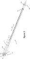
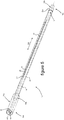
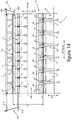
- the distribution devices 18 illustrated on the figures 3 to 6 are at least in part arranged to be housed in manifold boxes 7 illustrated in the figures 12 to 14 .
- the tubes 12 of the first layer 12a of tubes 12 of the bundle 6 which the heat exchanger 5 comprises are supplied with refrigerant fluid FR from the manifolds 7.
- the distribution devices 18 illustrated in each of these figures comprise at least a first duct 14 provided with a plurality of orifices 17 through which the refrigerant fluid FR admitted inside the first duct 14 is discharged, as illustrated. on the figures 12 to 14 .
- the inlet mouth 10 is for example formed of an opening passing longitudinally through a first end piece 23a fitted to the first longitudinal end 15 of the first duct 14.
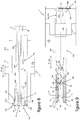
- the first end piece 23a is housed in a first support 25a intended to be brazed on the wall 7a of the manifold 7, as for example illustrated in FIG. figure 8 .
- the first support 25a is provided at a first longitudinal end 15a of the dispensing device 18.
- the first end piece 23a is housed inside a blind housing 36d formed in the first support 25a and crossed by the first duct 14, such as 'apparent on the figure 8 .
- a first angular positioning device 30a is interposed between the first duct 14 and the first support 25a.
- the first angular positioning device 30a has multiple positions to make it possible to orient the first duct 14 angularly about its longitudinal axis A1 according to various predefined angular positions.
- the orifices 17 can be angularly arranged via the first angular positioning device 30a according to an angular position selected by an operator when mounting the distribution device 18 inside the manifold.
- the first angular positioning device 30a comprises a first member 31a formed on the first end piece 23a and cooperating with a second member 31b formed on the first support 25a.
- the members 31a, 31b of the first angular positioning device 30a comprise a set of complementary shapes arranged in the example illustrated in grooves 34b cooperating with a notch 34a, each of the grooves 34b receiving a notch of the notch 34a which is assigned to it.
- the notching 34a forms the first member 31a of the first angular positioning device 30a and is provided on the first end piece 23a.
- the grooves 34b form a second member 31b of the first angular positioning device 30a and are formed on the first support 25a.
- the notching 34a and the grooves 34b extend in the longitudinal direction D2 of the distribution device 18, being angularly distributed around the longitudinal axis A1 of the first duct 14.
- the bringing into cooperation between the members 31a, 31b of the first device angular positioning 30a is thus produced longitudinally along the longitudinal axis A1 of the first duct 14.
- the axial abutment of the first duct 14 against the first support 25a provides an axial positioning of the distribution device 18 inside the manifold 7.
- the axial abutment of the first duct 14 against the first support 25a is for example produced via a stop 32 arranged as a collar and fitted to the first duct 14 at its first longitudinal end 15.
- the axial abutment of the first duct 14 against the first support 25a can also be carried out, for example, via the members 31a, 31b of the first angular positioning device 30a.
- the second longitudinal end 16 of the first duct 14 is closed by a second end piece 23b equipping the first duct 14.
- the second end piece 23b is housed inside a second support 25b intended to be brazed on the wall 7a of the manifold box.
- the second support 25b comprises a blind recess 36b receiving the second end piece 23b. More particularly, the second support 25b is in particular arranged in a blind tube 26b formed at a second longitudinal end 16a of the dispensing device 18. The blind tube 26b comprises the blind recess 36b for receiving the second end piece 23b.
- the first duct 14 houses a mixer 19 extending along a longitudinal axis A3 coaxial with the longitudinal axis A1 of the first duct 14.
- the mixer 19 is in particular formed of at least one permeable body through which the refrigerant fluid is suitable. to circulate.
- the mixer 19 is a member capable of mixing the refrigerant fluid flowing through it between its liquid phase and its gas phase.
- the permeable body forming the mixer 19 is capable of comprising specific openings 37 provided to open out into the orifices 17 of the first duct 14, as illustrated for example on the figures 9 and 13 .
- the figure 7 illustrates an exemplary embodiment of a mixer 19 capable of equipping a distribution device 18 of the invention.
- the mixer 19 is formed by a body 19a comprising propeller portions 19b successively disposed along the mixer 19 while being wound around the longitudinal axis A3 of the mixer 19.
- the propeller portions 19b are successively angularly offset with respect to each other around the longitudinal axis A3 of the mixer 19.
- the propeller portions 19b provide guide rails for the refrigerant flowing along the mixer 19 opening towards the 'exterior of the mixer 19 transversely to its longitudinal axis A3, leaving the openings 37 provided to be placed opposite the orifices 17 of the first duct 14.
- mixer 19 can be formed from a body comprising perforated reliefs providing obstacles against a laminar flow of refrigerant fluid therethrough.
- the mixer 19 may include one or more openings 37 arranged in a slot or in a window opening onto several orifices 17.
- the opening 37 is capable of extending over the major part of the mixer 19 by opening onto all of the orifices 17.
- the mixer mixer 19 can also be free from openings 37 specifically provided to open out towards the orifices 17 of the first duct 14.
- a second angular positioning device 30c is interposed between the first duct 14 and the mixer.
- the second angular positioning device 30c makes it possible in particular to orient the openings 37 of the mixer 19 in the direction of the orifices 17, as illustrated in the figures. figures 9 and 13 .
- the second angular positioning device 30c comprises a first member 38a formed at the end of the mixer 19 and cooperating with a second member 38b formed on the second end piece 23b.
- the second angular positioning device 30c is capable of having multiple angular positioning positions of the mixer 19 inside the first duct 14.
- the members 38a and 38b of the second angular positioning device 30c can have a parallelepipedal conformation forming multiple facets 39a angularly distributed around the longitudinal axis of the first duct 14.
- the mixer 19 can be disposed selectively at the interior of the first duct 14 in various angular positions.
- the first member 38a of the second angular positioning device 30c is arranged as a finger 39 housed in a second cavity 36c forming the second member 38b of the second angular positioning device 30c.
- the finger 39 and the second cavity 36c are centered on the longitudinal axis A3 of the mixer 19 and each have at least one facet 39a providing a rotational locking of the mixer 19 on itself.
- the second angular positioning device 30c has a single angular positioning position.
- the first member of the second angular positioning device 30c is formed by a male member arranged longitudinally as an extension of the mixer 19.
- the first member is housed in a said second cavity 36c of complementary shape forming the second member 38b.
- the members of the second angular positioning device 30c extend parallel to the longitudinal axis A3 of the mixer 19.
- the configurations of the members of the second angular positioning device 30c are generally of a configuration of centered revolution. on the longitudinal axis of the mixer and on the longitudinal axis of the first duct.
- the first member is arranged as a key 40a formed at the periphery of the longitudinal end of the mixer oriented towards the second end piece.
- the first member is formed by a relief 40b or 40c formed by machining or by crushing the longitudinal end of the mixer oriented towards the second end piece 23b.
- the relief 40b is for example of parallelepipedal conformation as illustrated in diagram (d).
- the relief 40c is for example still of ovoid conformation as illustrated in diagram (e).
- the first member is formed of a flat 40d formed along an extension of the longitudinal end of the mixer oriented towards the second end piece 23b.
- the second support 25b is in particular formed by an extension of a second duct 21 surrounding the first conduit 14.
- the first duct 14 is surrounded by the second duct 21 which comprises a plurality of passages 20 opening out towards the outside of the distribution device 18.
- the first duct 14 and the second duct 21 are preferably mounted coaxially via the first support 25a and the second support 25b, as for example illustrated in the figures 8 and 9 .
- the first support 25a forms a closure member 25c of the first longitudinal end 15b of the second duct 21.
- the second support 25b forms a closure member 25d of the second ends 16, 16b of the first duct 14 and of the second duct 21, via the blind recess 36b formed inside the second support 25b.
- the refrigerant fluid FR evacuated from the first duct 14 through the orifices 17 is capable of being evacuated outside the distribution device 18 through the passages 20 for supplying the refrigerant fluid to the tubes 12 of the bundle 6 which the exchanger comprises thermal 5.
- the orifices 17 are aligned along a first straight line L1 and the passages 20 are aligned along a second straight line L2.
- the first straight line L1 and the second straight line L2 are parallel to the longitudinal axis A1 of the first duct 14.
- the first straight line L1 and the second straight line L2 are arranged diametrically opposite to each other with respect to the longitudinal axis A1 of the first duct 14, in a direction DT transverse to the distribution device 18.
- the second duct 21 surrounds the first duct 14 at a transverse distance, leaving between them a channel 22 for circulating the refrigerant fluid discharged from the first duct 14 towards the passages 20 of the second duct 21.
- the refrigerant fluid FR discharged through the orifices 17 is able to circulate inside the channel 22 around the first duct 14 to the passages 20 for its evacuation out of the distribution device 18.
- a third angular positioning device 30b is interposed between the second support 25b and the wall 7a of the manifold 7.
- the third angular positioning device 30b makes it possible to orient the passages 20 according to at least one predetermined angular position around the longitudinal axis A1 of the first duct 14.
- the third angular positioning device 30b has a single angular positioning position.
- the orifices 17 can be positioned via the first angular positioning device 30a according to the angular position of the passages 20 defined by the third angular positioning device 30b.
- the third angular positioning device 30b is capable of having multiple angular positioning positions, for example by being arranged in a manner analogous to the configuration of the first angular positioning device 30a illustrated in FIG. figure 8 .
- the passages 20 and the orifices 17 can be angularly positioned with respect to each other at predefined angular positions. as shown on the figure 14 .
- the orifices 17 and / or the passages 20 can in particular be angularly positioned relative to the outlets 24 of the tubes 12 of the bundle 6 of the heat exchanger 5 oriented towards the chamber 9 delimited by the wall 7a of the manifold 7.
- the third angular positioning device 30b comprises a first member 33a formed on the second support 25b and cooperating with a second member 33b formed on the wall 7a of the manifold 7.
- the first member 33a of the third angular positioning device 30b is for example formed by a groove 35a formed at the end of the second support 25b.
- the groove 35a accommodates a plate 35b forming the second member 33b of the third angular positioning device 30b.
- the plate 35b is in particular attached to the wall 7a of the manifold 7 at its face oriented towards the outside of the chamber 9.
- the first member 33a of the third angular positioning device 30b is formed by a plate 35c attached to the end of the second support 25b.
- the plate 35c comprises a flat 35d carried against the wall 7a of the manifold 7.
- the third angular positioning device 30b can be arranged according to the various examples illustrated in the diagrams (c), (d), (e), and (f) of the figure 11 .
- the first longitudinal end 15b of the second duct 21 is housed in a first cavity 36a which the first support 25a comprises.
- the first support 25a thus forms a centering member between the second duct 21 and the first duct 14, the first end 15 of the first duct 14 being centered on the first support 25a via the first end piece 23a.
- the second end 16 of the first duct 14 is housed via the second end piece 23b in the blind recess 36b in the second support 25b.
- the second support 25b thus forms a relative centering member between the first duct 14 and the second duct 21.
- the coaxial positioning between the first duct 14 and the second duct 21 is obtained of quality by means of both of their longitudinal ends 15, 15b and 16, 16b.
- the bringing into cooperation between the members 33a, 33b of the third angular positioning device 30b is carried out longitudinally.
- An axial abutment between the members 33a, 33b of the third angular positioning device 30b provides a relative axial positioning between the first duct 14 and the second duct 21 and / or an axial positioning of the second duct 21 inside the box. collector 7.
- the axial positioning obtained between the first duct 14 and the second duct 21 makes it possible to arrange the orifices 17 and the passages 20 axially with respect to one another.
- the axial positioning of the distribution device 18 thus obtained inside the manifold 7 makes it possible to arrange at least the orifices 17 and / or the passages 20 axially with respect to each other and / or with respect to the outlets of the tubes of the beam on chamber 9.
- manifolds 7 of a heat exchanger 5 each include a distribution device 18.
- the distribution devices 18 are housed inside the chamber 9 formed inside the manifold 7, extending along a longitudinal direction D2 parallel to the longitudinal direction D1 of the manifold 7.
- the chamber 9 is delimited by the wall 7a of the manifold 7 extending along the longitudinal axis A1 of the duct 14 and through which the tubes 12 open. of the bundle 6 in the heat exchanger 5.
- the area of the wall 7a of the manifold 7 delimiting the chamber 9 is formed by eyelets 7b formed as an extension of plates delimiting the tubes 12 of the bundle 6.
- the eyelets 7b are successively butted in the longitudinal direction D1 of the manifold 7 and are traversed by the distribution device in its longitudinal direction D2.
- the distribution devices 18 are centered inside the chamber 9 of the manifold 7 on the median longitudinal axis A2 of extension of the manifold 7. According to a variant, the distribution devices 18 may be eccentric with respect to the median longitudinal axis A2 of the manifold 7.
- the angular positioning devices 30a, 30b, 30c are shown diagrammatically interposed between the members of the manifold 7 on which the members 31a, 31b are formed; 33a, 33b, 38a, 38b of the angular positioning devices 30a, 30b, 30c shown for example on the figures 3 to 6 and 8 to 11 .
- the manifold 7 is provided with a distribution device 18 illustrated in the figures 3 and 4 .
- the manifold 7 is provided with a distribution device 18 illustrated in the figures 3 and 4 and equipped with a mixer 19 as described and shown in the figures 6, 7 and 9 .
- the manifold 7 is provided with a distribution device 18 illustrated in the figures 3 and 4 surrounded by a second duct 21 as described and shown in the figures 5 and 6 and the figures 8 and 9 .
- the distribution device 18 is mounted on the collector box 7 by leaving a space E1 for circulating the refrigerant fluid FR between the first duct 14 and the wall 7a of the collector box 7 delimiting the chamber 9.
- the distribution device 18 partially occupies the volume of the chamber 9 in the transverse direction DT to the longitudinal axis A1 of the first duct 14.
- the orifices 17 open onto the chamber 9 by being oriented via the first angular positioning device 30a in an angular position determined with respect to the outlets 24 of the tubes 12 of the bundle 6 on the chamber 9.
- the orifices 17 open out into the chamber 9 opposite the outlets 24 of the tubes 12 of the bundle 6 on the chamber 9 in a direction transverse DT with respect to the longitudinal axis A1 of the first duct 14.
- the circulation path of the refrigerant fluid FR inside the chamber 9 prior to its distribution to the tubes 12 of the bundle 6 is thus optimized.
- the refrigerant fluid FR admitted into the first duct 14 is discharged through the orifices 17, then circulates inside the space El around the first duct 14 to the outlets 24 of the tubes 12 of the bundle 6 inside the the collector box 7.
- the mixer 19 is housed inside and along the first duct 14.
- the mixer 19 comprises the openings 37 which are arranged opposite the orifices 17 to promote the evacuation of the refrigerant fluid FR out of the mixer 19 towards the orifices 17
- the openings 37 and the orifices 17 are in direct communication with one another.
- the outlets 24 of the openings 37 oriented towards the outside of the mixer 19 are in direct communication with the outlets 24 of the orifices 17 towards the inside of the first duct 14.
- the arrangement facing the openings 37 and the orifices 17 is controlled via the second angular positioning device 30c.
- the refrigerant fluid FR admitted into the first duct 14 circulates through the mixer 19 and then is discharged out of the mixer 19 through the openings 37 to the orifices 17, through which the refrigerant fluid FR is discharged out of the first duct 14.
- the distribution device 18 occupies the entire volume of the chamber 9 in the transverse direction DT to the longitudinal axis A1 of the first duct 14.
- the distribution device 18 is in particular fixed by brazing via the second duct 21 on the wall 7a of the manifold 7.
- the second duct 21 surrounds the first duct 14 at a transverse distance DT, leaving between them the channel 22 for circulating the refrigerant fluid FR inside the distribution device 18.
- the orifices 17 are oriented via the first angular positioning device 30a and / or the third angular positioning device 30b to the opposite of the passages 20 relative to the longitudinal axis A1 of the first duct 14.
- the passages 20 open individually into the outlets 24 of the tubes 12 of the bundle 6.
- the configuration of the passages 20 matches at least the configuration of the outlets 24 of the tubes 12 of the bundle 6 through the wall 7a of the manifold 7 delimiting the chamber 9.
- the distribution of the refrigerant fluid FR to each of the tubes 12 of beam 6 is obtained reliably and efficiently.
- the refrigerant fluid FR is evacuated out of the distribution device 18 through the passages 20 directly towards each of the tubes 12 of the bundle 6, in a homogeneous manner for all the tubes 12 of the bundle 6.
- the refrigerant fluid FR admitted into the first duct 14 is evacuated through the orifices 17 towards the channel 22, circulates inside the channel 22 around the first duct 14 then is evacuated out of the second duct 21 through the passages 20 towards the tubes 12 of bundle 6.
Landscapes
- Engineering & Computer Science (AREA)
- Physics & Mathematics (AREA)
- Thermal Sciences (AREA)
- Mechanical Engineering (AREA)
- General Engineering & Computer Science (AREA)
- Heat-Exchange Devices With Radiators And Conduit Assemblies (AREA)
Claims (15)
- Sammelkasten (7) für ein Kältemittel (FR) für einen Wärmetauscher (5), wobei der Sammelkasten (7) von einer Wand (7a) gebildet wird und wenigstens ein Rohr (14) aufnimmt, das sich entlang einer Längsachse (A1) erstreckt, wobei eines der Längsenden (15) des Rohres (14) mit einer Eintrittsöffnung (10) für den Einlass von Kältemittel (FR) ins Innere des Rohres (14) in Verbindung steht, wobei das Rohr (14) wenigstens eine Öffnung (17) aufweist, die in einer Richtung (DT) quer zu seiner Längsachse (A1) ausgerichtet ist, wobei der Sammelkasten (7) mit wenigstens einer Vorrichtung zur Winkelpositionierung (30a, 30b) ausgestattet ist, welche wenigstens das Rohr (14) um seine Längsachse (A1) in einer vorbestimmten Winkelposition in Bezug auf die Wand (7a) des Sammelkastens (7) anordnet,
dadurch gekennzeichnet, dass die Vorrichtung zur Winkelpositionierung (30a, 30b) ein Paar von Elementen (31a-31b; 33a-33b) umfasst, die über wenigstens einen Satz von komplementären Formen (34a-34b; 35a-35b) zusammenwirken, wobei ein erstes Element (31a) der ersten Vorrichtung zur Winkelpositionierung (30a) an einem beliebigen Längsende (15, 16) des Rohres (14) ausgebildet ist und mit einem zweiten Element (31b) zusammenwirkt, das an der Wand (7a) des Sammelkastens (7) ausgebildet ist. - Sammelkasten (7) nach Anspruch 1, wobei die Vorrichtung zur Winkelpositionierung eine erste Vorrichtung zur Winkelpositionierung (30a) ist, die zur Querpositionierung des Rohres (14) im Inneren des Sammelkastens (7) in Bezug auf die Längsachse (A1) bestimmt ist.
- Sammelkasten (7) nach Anspruch 2, wobei die erste Vorrichtung zur Winkelpositionierung (30a) einen Anschlag (32) zur axialen Positionierung des Rohres (14) im Sammelkasten (7) entlang seiner Längsachse (A1) umfasst.
- Sammelkasten (7) nach einem der Ansprüche 2 oder 3, wobei die erste Vorrichtung zur Winkelpositionierung (30a) mehrere ausgewählte Positionen der Winkelpositionierung des Rohres (14) ermöglicht.
- Sammelkasten (7) nach einem der Ansprüche 2 bis 4, wobei die erste Vorrichtung zur Winkelpositionierung (30a) zwischen dem Rohr (14) und der Wand (7a) des Sammelkastens (7) angeordnet ist.
- Sammelkasten (7) nach einem der vorhergehenden Ansprüche, wobei das Rohr (14) einen Mischer (19) zum Mischen der flüssigen Phase und der gasförmigen Phase des Kältemittels (FR) aufnimmt.
- Sammelkasten (7) nach einem der vorhergehenden Ansprüche, wobei wenigstens ein Schließelement (25c, 25d) an wenigstens einem der Längsenden (15, 16) des Rohres (14) positioniert ist, wobei ein gegebenes Schließelement (25c, 25d) wenigstens ein zweites Längsende (16) des Rohres (14) schließt.
- Sammelkasten (7) nach einem der vorhergehenden Ansprüche, wobei der Sammelkasten (7) das Rohr (14), erstes Rohr (14) genannt, und ein zweites Rohr (21) umfasst, welches das erste Rohr (14) umgibt und welches wenigstens einen Durchlass (20) zum Ablassen des Kältemittels (FR), das von dem ersten Rohr (14) durch die Öffnung (17) hindurch abgelassen wurde, aus dem zweiten Rohr (21) aufweist.
- Wärmetauscher (5), welcher wenigstens einen Sammelkasten (7) gemäß einem der vorhergehenden Ansprüche umfasst.
- Wärmetauscher (5) nach dem vorhergehenden Anspruch, wobei Rohre (12) eines Bündels (6) von Rohren (12) in eine Kammer (9) münden, die von der Wand (7a) des Sammelkastens (7) gebildet wird, wobei sie nacheinander in einer Längserstreckungsrichtung (D1) des Sammelkastens (7) angeordnet sind, und wobei die Kammer (9) wenigstens das erste Rohr (14) und/oder das zweite Rohr aufnimmt, wobei wenigstens eine Vorrichtung zur Winkelpositionierung (30a, 30b, 30c) wenigstens das erste Rohr (14) in einer vorbestimmten Winkelposition um seine Längsachse (A1) in Bezug auf die Position der Mündungen (24) der Rohre (12) des Bündels (6) in die Kammer (9) positioniert.
- Wärmetauscher (5) nach Anspruch 10, wobei die Öffnung (17) in die Kammer (9) gegenüber den Mündungen (24) der Rohre (12) des Bündels (6) in die Kammer (9) mündet, bezogen auf die Längsachse (A1) des ersten Rohres (14).
- Wärmetauscher (5) nach einem der Ansprüche 10 und 11, wobei sich das zweite Rohr (21) in Kontakt mit der Wand (7a) des Sammelkastens (7) befindet, wobei sich wenigstens ein Durchlass (20) des zweiten Rohres (21) gegenüber der Mündung (24) wenigstens eines Rohres (12) des Bündels (6) in die Kammer (9) befindet.
- Verwendung eines Wärmetauschers (5) nach einem der Ansprüche 9 bis 12 als Verdampfer.
- Kältemittelkreislauf (1), welcher wenigstens einen Kompressor (2), einen Kondensator (3), eine Expansionsvorrichtung (4) und einen Wärmetauscher (5) nach einem der Ansprüche 9 bis 12 umfasst, die von einem Kältemittel (FR) durchströmt werden.
- Lüftungs-, Heizungs- und/oder Klimaanlage, welche dafür ausgelegt ist, ein Fahrzeug damit auszurüsten, und wenigstens einen Wärmetauscher (5) nach einem der Ansprüche 9 bis 12 umfasst.
Applications Claiming Priority (2)
| Application Number | Priority Date | Filing Date | Title |
|---|---|---|---|
| FR1661751A FR3061281B1 (fr) | 2016-11-30 | 2016-11-30 | Boite collectrice d'un fluide refrigerant comprenant au moins un dispositif de positionnement angulaire d'un conduit |
| PCT/FR2017/053306 WO2018100303A1 (fr) | 2016-11-30 | 2017-11-30 | Boîte collectrice d'un fluide réfrigérant comprenant au moins un dispositif de positionnement angulaire d'un conduit |
Publications (2)
| Publication Number | Publication Date |
|---|---|
| EP3548823A1 EP3548823A1 (de) | 2019-10-09 |
| EP3548823B1 true EP3548823B1 (de) | 2021-08-18 |
Family
ID=58162794
Family Applications (1)
| Application Number | Title | Priority Date | Filing Date |
|---|---|---|---|
| EP17816948.8A Active EP3548823B1 (de) | 2016-11-30 | 2017-11-30 | Sammelrohr zur aufnahme eines kältemittels mit mindestens einer vorrichtung zur winkelpositionierung eines rohres |
Country Status (4)
| Country | Link |
|---|---|
| EP (1) | EP3548823B1 (de) |
| CN (1) | CN110192077B (de) |
| FR (1) | FR3061281B1 (de) |
| WO (1) | WO2018100303A1 (de) |
Family Cites Families (13)
| Publication number | Priority date | Publication date | Assignee | Title |
|---|---|---|---|---|
| GB285524A (en) * | 1926-10-08 | 1928-02-08 | Charles Harold Potts | Improvements in or relating to heat exchangers |
| US3976128A (en) * | 1975-06-12 | 1976-08-24 | Ford Motor Company | Plate and fin heat exchanger |
| IL107850A0 (en) * | 1992-12-07 | 1994-04-12 | Multistack Int Ltd | Improvements in plate heat exchangers |
| NO320779B1 (no) * | 2004-06-14 | 2006-01-30 | Inst Energiteknik | Innlopsinnretning |
| DE102006059504A1 (de) * | 2005-12-14 | 2007-06-28 | Behr Gmbh & Co. Kg | Wärmepumpe |
| US8919425B2 (en) * | 2008-09-02 | 2014-12-30 | Halla Visteon Climate Control Corporation | Flow control valve and heat exchanger equipped with same |
| US20110290465A1 (en) | 2010-06-01 | 2011-12-01 | Delphi Technologies, Inc. | Orientation insensitive refrigerant distributor tube |
| CN101865574B (zh) * | 2010-06-21 | 2013-01-30 | 三花控股集团有限公司 | 换热器 |
| CN102072684B (zh) * | 2011-01-06 | 2012-10-17 | 三花控股集团有限公司 | 制冷剂分配装置和具有它的换热器 |
| WO2014117017A1 (en) * | 2013-01-25 | 2014-07-31 | Trane International Inc. | Capacity modulating an expansion device of a hvac system |
| CN103486896B (zh) * | 2013-07-30 | 2015-05-27 | 杭州三花微通道换热器有限公司 | 集流管组件和具有该集流管组件的换热器 |
| EP3143850B1 (de) * | 2014-05-15 | 2020-07-01 | Hewlett-Packard Enterprise Development LP | Flüssigkeitsverteiler |
| CN104048548B (zh) * | 2014-05-26 | 2016-01-27 | 杭州三花微通道换热器有限公司 | 可调节的制冷剂分配装置和具有它的换热器 |
-
2016
- 2016-11-30 FR FR1661751A patent/FR3061281B1/fr not_active Expired - Fee Related
-
2017
- 2017-11-30 WO PCT/FR2017/053306 patent/WO2018100303A1/fr not_active Ceased
- 2017-11-30 CN CN201780083671.0A patent/CN110192077B/zh active Active
- 2017-11-30 EP EP17816948.8A patent/EP3548823B1/de active Active
Also Published As
| Publication number | Publication date |
|---|---|
| EP3548823A1 (de) | 2019-10-09 |
| FR3061281B1 (fr) | 2019-07-12 |
| WO2018100303A1 (fr) | 2018-06-07 |
| CN110192077A (zh) | 2019-08-30 |
| FR3061281A1 (fr) | 2018-06-29 |
| CN110192077B (zh) | 2021-08-10 |
Similar Documents
| Publication | Publication Date | Title |
|---|---|---|
| EP3423770B1 (de) | Vorratsbehälter für phasenwechselmaterial mit einem füllrohr zum befüllen desselben für einen wärmetauscher einer kraftfahrzeug-klimaanlage | |
| EP3548825B1 (de) | Vorrichtung zur verteilung eines kältemittels in einem sammelkasten eines wärmeaustauschers | |
| FR2815113A1 (fr) | Echangeur de chaleur en serpentin | |
| FR3059397B1 (fr) | Dispositif de distribution d’un fluide refrigerant a l’interieur de tubes d’un echangeur de chaleur constitutif d’un circuit de fluide refrigerant | |
| WO2018100302A1 (fr) | Dispositif d'homogénéisation de la distribution d'un fluide réfrigérant à l'intérieur de tubes d'un échangeur de chaleur constitutif d'un circuit de fluide réfrigérant | |
| EP3548823B1 (de) | Sammelrohr zur aufnahme eines kältemittels mit mindestens einer vorrichtung zur winkelpositionierung eines rohres | |
| FR3061280A1 (fr) | Dispositif de distribution d'un fluide refrigerant a l'interieur d'une boite collectrice d'un echangeur thermique pour une installation de conditionnement d'air d'un vehicule | |
| EP3548827B1 (de) | Vorrichtung zur verteilung eines kühlmittels in einem sammelkasten eines wärmeaustauschers für eine klimaanlage eines fahrzeugs | |
| FR3059405B1 (fr) | Dispositif de distribution d'un fluide refrigerant a l'interieur d'une boite collectrice d'un echangeur thermique | |
| EP2980509A1 (de) | Einlassverteiler für einen verdampfer, herstellungsverfahren eines solchen verteilers, verdampfer, der einen solchen verteiler umfasst, und thermische anlage mit zweiphasen-wärmeübertragungsmittel | |
| FR3061283B1 (fr) | Dispositif de repartition d’un fluide refrigerant pour une boite collectrice d’un echangeur de chaleur | |
| FR3075345A1 (fr) | Boite collectrice d'un echangeur thermique logeant un dispositif de distribution d'un fluide refrigerant maintenu via un organe de centrage. | |
| FR3059396A1 (fr) | Dispositif de distribution d'un fluide refrigerant a l'interieur d'une boite collectrice d'un echangeur thermique | |
| FR3059408A1 (fr) | Dispositif de distribution d'un fluide refrigerant a l'interieur d'une boite collectrice d'un echangeur thermique | |
| EP3548826B1 (de) | Vorrichtung zum mischen einer kühlflüssigkeit in einem sammelkasten eines wärmeaustauschers | |
| FR3075349A1 (fr) | Dispositif de distribution d'un fluide refrigerant a l'interieur d'une boite collectrice d'un echangeur thermique, et boite collectrice equipee d'un tel dispositif de distribution | |
| FR3097954A1 (fr) | Plaque constitutive d’un échangeur de chaleur et échangeur de chaleur comprenant au moins une telle plaque | |
| WO2018100299A1 (fr) | Dispositif d'homogénéisation de la distribution d'un fluide réfrigérant à l'intérieur de tubes d'un échangeur de chaleur constitutif d'un circuit de fluide réfrigérant | |
| FR3059406B1 (fr) | Dispositif de mixage d'un fluide refrigerant a l'interieur d'une boite collectrice d'un echangeur thermique pour une installation de conditionnement d'air d'un vehicule | |
| EP3548824A1 (de) | Vorrichtung zur homogenisierung der verteilung eines kältemittels im innern von rohren eines einen kältemittelkreislauf bildenden wärmetauschers | |
| FR3059394B1 (fr) | Dispositif d’homogeneisation de la distribution d’un fluide refrigerant a l’interieur de tubes d’un echangeur de chaleur constitutif d’un circuit de fluide refrigerant | |
| FR3059398A1 (fr) | Dispositif de distribution d'un fluide refrigerant a l'interieur d'une boite collectrice d'un echangeur thermique pour une installation de conditionnement d'air d'un vehicule | |
| FR3075347A1 (fr) | Dispositif de distribution d'un fluide refrigerant destine a etre loge dans une boite collectrice d'un echangeur de chaleur | |
| FR3081516A1 (fr) | Dispositif de refroidissement des gaz recircules egr equipe d'un conduit peripherique de distribution de liquide de refroidissement | |
| FR3075348A1 (fr) | Dispositif de distribution d'un fluide refrigerant destine a etre loge dans une boite collectrice d'un echangeur de chaleur |
Legal Events
| Date | Code | Title | Description |
|---|---|---|---|
| STAA | Information on the status of an ep patent application or granted ep patent |
Free format text: STATUS: UNKNOWN |
|
| STAA | Information on the status of an ep patent application or granted ep patent |
Free format text: STATUS: THE INTERNATIONAL PUBLICATION HAS BEEN MADE |
|
| PUAI | Public reference made under article 153(3) epc to a published international application that has entered the european phase |
Free format text: ORIGINAL CODE: 0009012 |
|
| STAA | Information on the status of an ep patent application or granted ep patent |
Free format text: STATUS: REQUEST FOR EXAMINATION WAS MADE |
|
| 17P | Request for examination filed |
Effective date: 20190614 |
|
| AK | Designated contracting states |
Kind code of ref document: A1 Designated state(s): AL AT BE BG CH CY CZ DE DK EE ES FI FR GB GR HR HU IE IS IT LI LT LU LV MC MK MT NL NO PL PT RO RS SE SI SK SM TR |
|
| AX | Request for extension of the european patent |
Extension state: BA ME |
|
| DAV | Request for validation of the european patent (deleted) | ||
| DAX | Request for extension of the european patent (deleted) | ||
| GRAP | Despatch of communication of intention to grant a patent |
Free format text: ORIGINAL CODE: EPIDOSNIGR1 |
|
| STAA | Information on the status of an ep patent application or granted ep patent |
Free format text: STATUS: GRANT OF PATENT IS INTENDED |
|
| GRAJ | Information related to disapproval of communication of intention to grant by the applicant or resumption of examination proceedings by the epo deleted |
Free format text: ORIGINAL CODE: EPIDOSDIGR1 |
|
| GRAP | Despatch of communication of intention to grant a patent |
Free format text: ORIGINAL CODE: EPIDOSNIGR1 |
|
| GRAJ | Information related to disapproval of communication of intention to grant by the applicant or resumption of examination proceedings by the epo deleted |
Free format text: ORIGINAL CODE: EPIDOSDIGR1 |
|
| GRAP | Despatch of communication of intention to grant a patent |
Free format text: ORIGINAL CODE: EPIDOSNIGR1 |
|
| INTG | Intention to grant announced |
Effective date: 20210217 |
|
| INTG | Intention to grant announced |
Effective date: 20210226 |
|
| INTG | Intention to grant announced |
Effective date: 20210310 |
|
| GRAS | Grant fee paid |
Free format text: ORIGINAL CODE: EPIDOSNIGR3 |
|
| GRAA | (expected) grant |
Free format text: ORIGINAL CODE: 0009210 |
|
| STAA | Information on the status of an ep patent application or granted ep patent |
Free format text: STATUS: THE PATENT HAS BEEN GRANTED |
|
| AK | Designated contracting states |
Kind code of ref document: B1 Designated state(s): AL AT BE BG CH CY CZ DE DK EE ES FI FR GB GR HR HU IE IS IT LI LT LU LV MC MK MT NL NO PL PT RO RS SE SI SK SM TR |
|
| REG | Reference to a national code |
Ref country code: GB Ref legal event code: FG4D Free format text: NOT ENGLISH |
|
| REG | Reference to a national code |
Ref country code: CH Ref legal event code: EP |
|
| REG | Reference to a national code |
Ref country code: DE Ref legal event code: R096 Ref document number: 602017044399 Country of ref document: DE |
|
| REG | Reference to a national code |
Ref country code: IE Ref legal event code: FG4D Free format text: LANGUAGE OF EP DOCUMENT: FRENCH Ref country code: AT Ref legal event code: REF Ref document number: 1422009 Country of ref document: AT Kind code of ref document: T Effective date: 20210915 |
|
| REG | Reference to a national code |
Ref country code: LT Ref legal event code: MG9D |
|
| REG | Reference to a national code |
Ref country code: NL Ref legal event code: MP Effective date: 20210818 |
|
| REG | Reference to a national code |
Ref country code: AT Ref legal event code: MK05 Ref document number: 1422009 Country of ref document: AT Kind code of ref document: T Effective date: 20210818 |
|
| PG25 | Lapsed in a contracting state [announced via postgrant information from national office to epo] |
Ref country code: SE Free format text: LAPSE BECAUSE OF FAILURE TO SUBMIT A TRANSLATION OF THE DESCRIPTION OR TO PAY THE FEE WITHIN THE PRESCRIBED TIME-LIMIT Effective date: 20210818 Ref country code: RS Free format text: LAPSE BECAUSE OF FAILURE TO SUBMIT A TRANSLATION OF THE DESCRIPTION OR TO PAY THE FEE WITHIN THE PRESCRIBED TIME-LIMIT Effective date: 20210818 Ref country code: HR Free format text: LAPSE BECAUSE OF FAILURE TO SUBMIT A TRANSLATION OF THE DESCRIPTION OR TO PAY THE FEE WITHIN THE PRESCRIBED TIME-LIMIT Effective date: 20210818 Ref country code: ES Free format text: LAPSE BECAUSE OF FAILURE TO SUBMIT A TRANSLATION OF THE DESCRIPTION OR TO PAY THE FEE WITHIN THE PRESCRIBED TIME-LIMIT Effective date: 20210818 Ref country code: FI Free format text: LAPSE BECAUSE OF FAILURE TO SUBMIT A TRANSLATION OF THE DESCRIPTION OR TO PAY THE FEE WITHIN THE PRESCRIBED TIME-LIMIT Effective date: 20210818 Ref country code: BG Free format text: LAPSE BECAUSE OF FAILURE TO SUBMIT A TRANSLATION OF THE DESCRIPTION OR TO PAY THE FEE WITHIN THE PRESCRIBED TIME-LIMIT Effective date: 20211118 Ref country code: AT Free format text: LAPSE BECAUSE OF FAILURE TO SUBMIT A TRANSLATION OF THE DESCRIPTION OR TO PAY THE FEE WITHIN THE PRESCRIBED TIME-LIMIT Effective date: 20210818 Ref country code: LT Free format text: LAPSE BECAUSE OF FAILURE TO SUBMIT A TRANSLATION OF THE DESCRIPTION OR TO PAY THE FEE WITHIN THE PRESCRIBED TIME-LIMIT Effective date: 20210818 Ref country code: PT Free format text: LAPSE BECAUSE OF FAILURE TO SUBMIT A TRANSLATION OF THE DESCRIPTION OR TO PAY THE FEE WITHIN THE PRESCRIBED TIME-LIMIT Effective date: 20211220 Ref country code: NO Free format text: LAPSE BECAUSE OF FAILURE TO SUBMIT A TRANSLATION OF THE DESCRIPTION OR TO PAY THE FEE WITHIN THE PRESCRIBED TIME-LIMIT Effective date: 20211118 |
|
| PG25 | Lapsed in a contracting state [announced via postgrant information from national office to epo] |
Ref country code: PL Free format text: LAPSE BECAUSE OF FAILURE TO SUBMIT A TRANSLATION OF THE DESCRIPTION OR TO PAY THE FEE WITHIN THE PRESCRIBED TIME-LIMIT Effective date: 20210818 Ref country code: LV Free format text: LAPSE BECAUSE OF FAILURE TO SUBMIT A TRANSLATION OF THE DESCRIPTION OR TO PAY THE FEE WITHIN THE PRESCRIBED TIME-LIMIT Effective date: 20210818 Ref country code: GR Free format text: LAPSE BECAUSE OF FAILURE TO SUBMIT A TRANSLATION OF THE DESCRIPTION OR TO PAY THE FEE WITHIN THE PRESCRIBED TIME-LIMIT Effective date: 20211119 |
|
| PG25 | Lapsed in a contracting state [announced via postgrant information from national office to epo] |
Ref country code: NL Free format text: LAPSE BECAUSE OF FAILURE TO SUBMIT A TRANSLATION OF THE DESCRIPTION OR TO PAY THE FEE WITHIN THE PRESCRIBED TIME-LIMIT Effective date: 20210818 |
|
| PG25 | Lapsed in a contracting state [announced via postgrant information from national office to epo] |
Ref country code: DK Free format text: LAPSE BECAUSE OF FAILURE TO SUBMIT A TRANSLATION OF THE DESCRIPTION OR TO PAY THE FEE WITHIN THE PRESCRIBED TIME-LIMIT Effective date: 20210818 |
|
| REG | Reference to a national code |
Ref country code: DE Ref legal event code: R097 Ref document number: 602017044399 Country of ref document: DE |
|
| PG25 | Lapsed in a contracting state [announced via postgrant information from national office to epo] |
Ref country code: SM Free format text: LAPSE BECAUSE OF FAILURE TO SUBMIT A TRANSLATION OF THE DESCRIPTION OR TO PAY THE FEE WITHIN THE PRESCRIBED TIME-LIMIT Effective date: 20210818 Ref country code: SK Free format text: LAPSE BECAUSE OF FAILURE TO SUBMIT A TRANSLATION OF THE DESCRIPTION OR TO PAY THE FEE WITHIN THE PRESCRIBED TIME-LIMIT Effective date: 20210818 Ref country code: RO Free format text: LAPSE BECAUSE OF FAILURE TO SUBMIT A TRANSLATION OF THE DESCRIPTION OR TO PAY THE FEE WITHIN THE PRESCRIBED TIME-LIMIT Effective date: 20210818 Ref country code: EE Free format text: LAPSE BECAUSE OF FAILURE TO SUBMIT A TRANSLATION OF THE DESCRIPTION OR TO PAY THE FEE WITHIN THE PRESCRIBED TIME-LIMIT Effective date: 20210818 Ref country code: CZ Free format text: LAPSE BECAUSE OF FAILURE TO SUBMIT A TRANSLATION OF THE DESCRIPTION OR TO PAY THE FEE WITHIN THE PRESCRIBED TIME-LIMIT Effective date: 20210818 Ref country code: AL Free format text: LAPSE BECAUSE OF FAILURE TO SUBMIT A TRANSLATION OF THE DESCRIPTION OR TO PAY THE FEE WITHIN THE PRESCRIBED TIME-LIMIT Effective date: 20210818 |
|
| PLBE | No opposition filed within time limit |
Free format text: ORIGINAL CODE: 0009261 |
|
| STAA | Information on the status of an ep patent application or granted ep patent |
Free format text: STATUS: NO OPPOSITION FILED WITHIN TIME LIMIT |
|
| PG25 | Lapsed in a contracting state [announced via postgrant information from national office to epo] |
Ref country code: MC Free format text: LAPSE BECAUSE OF FAILURE TO SUBMIT A TRANSLATION OF THE DESCRIPTION OR TO PAY THE FEE WITHIN THE PRESCRIBED TIME-LIMIT Effective date: 20210818 |
|
| REG | Reference to a national code |
Ref country code: CH Ref legal event code: PL |
|
| 26N | No opposition filed |
Effective date: 20220519 |
|
| GBPC | Gb: european patent ceased through non-payment of renewal fee |
Effective date: 20211130 |
|
| PG25 | Lapsed in a contracting state [announced via postgrant information from national office to epo] |
Ref country code: LU Free format text: LAPSE BECAUSE OF NON-PAYMENT OF DUE FEES Effective date: 20211130 Ref country code: IT Free format text: LAPSE BECAUSE OF FAILURE TO SUBMIT A TRANSLATION OF THE DESCRIPTION OR TO PAY THE FEE WITHIN THE PRESCRIBED TIME-LIMIT Effective date: 20210818 Ref country code: BE Free format text: LAPSE BECAUSE OF NON-PAYMENT OF DUE FEES Effective date: 20211130 |
|
| REG | Reference to a national code |
Ref country code: BE Ref legal event code: MM Effective date: 20211130 |
|
| PG25 | Lapsed in a contracting state [announced via postgrant information from national office to epo] |
Ref country code: SI Free format text: LAPSE BECAUSE OF FAILURE TO SUBMIT A TRANSLATION OF THE DESCRIPTION OR TO PAY THE FEE WITHIN THE PRESCRIBED TIME-LIMIT Effective date: 20210818 Ref country code: LI Free format text: LAPSE BECAUSE OF NON-PAYMENT OF DUE FEES Effective date: 20211130 Ref country code: CH Free format text: LAPSE BECAUSE OF NON-PAYMENT OF DUE FEES Effective date: 20211130 |
|
| PG25 | Lapsed in a contracting state [announced via postgrant information from national office to epo] |
Ref country code: IE Free format text: LAPSE BECAUSE OF NON-PAYMENT OF DUE FEES Effective date: 20211130 Ref country code: GB Free format text: LAPSE BECAUSE OF NON-PAYMENT OF DUE FEES Effective date: 20211130 |
|
| PG25 | Lapsed in a contracting state [announced via postgrant information from national office to epo] |
Ref country code: CY Free format text: LAPSE BECAUSE OF FAILURE TO SUBMIT A TRANSLATION OF THE DESCRIPTION OR TO PAY THE FEE WITHIN THE PRESCRIBED TIME-LIMIT Effective date: 20210818 |
|
| P01 | Opt-out of the competence of the unified patent court (upc) registered |
Effective date: 20230528 |
|
| PG25 | Lapsed in a contracting state [announced via postgrant information from national office to epo] |
Ref country code: HU Free format text: LAPSE BECAUSE OF FAILURE TO SUBMIT A TRANSLATION OF THE DESCRIPTION OR TO PAY THE FEE WITHIN THE PRESCRIBED TIME-LIMIT; INVALID AB INITIO Effective date: 20171130 |
|
| PG25 | Lapsed in a contracting state [announced via postgrant information from national office to epo] |
Ref country code: MK Free format text: LAPSE BECAUSE OF FAILURE TO SUBMIT A TRANSLATION OF THE DESCRIPTION OR TO PAY THE FEE WITHIN THE PRESCRIBED TIME-LIMIT Effective date: 20210818 |
|
| PG25 | Lapsed in a contracting state [announced via postgrant information from national office to epo] |
Ref country code: MT Free format text: LAPSE BECAUSE OF FAILURE TO SUBMIT A TRANSLATION OF THE DESCRIPTION OR TO PAY THE FEE WITHIN THE PRESCRIBED TIME-LIMIT Effective date: 20210818 |
|
| PG25 | Lapsed in a contracting state [announced via postgrant information from national office to epo] |
Ref country code: TR Free format text: LAPSE BECAUSE OF FAILURE TO SUBMIT A TRANSLATION OF THE DESCRIPTION OR TO PAY THE FEE WITHIN THE PRESCRIBED TIME-LIMIT Effective date: 20210818 |
|
| PGFP | Annual fee paid to national office [announced via postgrant information from national office to epo] |
Ref country code: DE Payment date: 20251117 Year of fee payment: 9 |
|
| PGFP | Annual fee paid to national office [announced via postgrant information from national office to epo] |
Ref country code: FR Payment date: 20251128 Year of fee payment: 9 |