EP3549849B1 - Diebstahlsicherung für fahrrad - Google Patents
Diebstahlsicherung für fahrrad Download PDFInfo
- Publication number
- EP3549849B1 EP3549849B1 EP19166640.3A EP19166640A EP3549849B1 EP 3549849 B1 EP3549849 B1 EP 3549849B1 EP 19166640 A EP19166640 A EP 19166640A EP 3549849 B1 EP3549849 B1 EP 3549849B1
- Authority
- EP
- European Patent Office
- Prior art keywords
- theft
- bicycle
- pedal
- intended
- theft device
- Prior art date
- Legal status (The legal status is an assumption and is not a legal conclusion. Google has not performed a legal analysis and makes no representation as to the accuracy of the status listed.)
- Active
Links
Images

Classifications
-
- B—PERFORMING OPERATIONS; TRANSPORTING
- B62—LAND VEHICLES FOR TRAVELLING OTHERWISE THAN ON RAILS
- B62H—CYCLE STANDS; SUPPORTS OR HOLDERS FOR PARKING OR STORING CYCLES; APPLIANCES PREVENTING OR INDICATING UNAUTHORIZED USE OR THEFT OF CYCLES; LOCKS INTEGRAL WITH CYCLES; DEVICES FOR LEARNING TO RIDE CYCLES
- B62H1/00—Supports or stands forming part of or attached to cycles
- B62H1/08—Pedal supports
-
- B—PERFORMING OPERATIONS; TRANSPORTING
- B62—LAND VEHICLES FOR TRAVELLING OTHERWISE THAN ON RAILS
- B62H—CYCLE STANDS; SUPPORTS OR HOLDERS FOR PARKING OR STORING CYCLES; APPLIANCES PREVENTING OR INDICATING UNAUTHORIZED USE OR THEFT OF CYCLES; LOCKS INTEGRAL WITH CYCLES; DEVICES FOR LEARNING TO RIDE CYCLES
- B62H3/00—Separate supports or holders for parking or storing cycles
- B62H3/10—Separate supports or holders for parking or storing cycles involving forked supports or brackets embracing the bottom part of the frame
-
- B—PERFORMING OPERATIONS; TRANSPORTING
- B62—LAND VEHICLES FOR TRAVELLING OTHERWISE THAN ON RAILS
- B62H—CYCLE STANDS; SUPPORTS OR HOLDERS FOR PARKING OR STORING CYCLES; APPLIANCES PREVENTING OR INDICATING UNAUTHORIZED USE OR THEFT OF CYCLES; LOCKS INTEGRAL WITH CYCLES; DEVICES FOR LEARNING TO RIDE CYCLES
- B62H5/00—Appliances preventing or indicating unauthorised use or theft of cycles; Locks integral with cycles
- B62H5/08—Appliances preventing or indicating unauthorised use or theft of cycles; Locks integral with cycles preventing the drive
- B62H5/10—Appliances preventing or indicating unauthorised use or theft of cycles; Locks integral with cycles preventing the drive acting on a pedal crank
Definitions
- the present invention relates to an anti-theft device for a bicycle, the bicycle comprising a bottom bracket crank comprising a crank body with a first end connected to a crank axle and a second end connected to an axle of a pedal, the anti-theft device comprising a first anti-theft part intended to be secured to the ground and having a housing in which is placed the bottom bracket crank and a second anti-theft part forming a removable lock which is intended to cover the first anti-theft part so as to lock the bottom bracket crank in the first part of the lock.
- a padlock is used to lock a wheel of the bicycle to the frame of the bicycle to prevent rotation of the wheel, or to secure the frame of the bicycle or the wheel to a fixed object such as street furniture.
- the document FR3025774 describes in particular an anti-theft device integrated into the bicycle and the purpose of which is to lock the bicycle so as to prevent its normal use in the event of theft, by blocking the axis of the crankset.
- the document EP0949139 describes a fixed anti-theft device, comprising a receiving structure secured to the ground in which the bicycle will be inserted to keep it upright, and the device will be locked by a barrel provided by the user.
- this kind of device takes up a lot of floor space and is not very aesthetic.
- the document US 9840855 describes another type of anti-theft device for a bicycle. It relates to an anti-theft device for a bicycle for locking on a structure secured to the ground a pedal crank of a bicycle.
- the cranks which serve as the main transmission of the bicycle and which connect the pedal to the crown carrying the chain, do not vary much from one model of bicycle to another.
- the central position of the bottom bracket crank over the entire frame of the bicycle is a preferred position for locking a parked bicycle.
- the anti-theft device for a bicycle with a bottom bracket crank comprises a first anti-theft part with a recess adapted to receive the axle of the bottom bracket and a second anti-theft part forming a lock integral with the first part of anti-theft device, and being able to switch from a standby position to a locking around the crank axle.
- this anti-theft device has a complex structure and locking mechanism.
- the crank axle is not always at the same height from the ground and the use of this type of anti-theft device may require a certain dexterity to hold the bicycle with the pedal axle housed in the first anti-theft part while closing the lock of the second anti-theft part.
- the object of the invention is to provide another anti-theft device for a bicycle with a crank which makes it possible to improve the protection against bicycle theft, which is easily usable for the great majority of bicycles and which can be mounted on existing infrastructure.
- the invention relates to an anti-theft device for a bicycle, the bicycle comprising a pedal crank comprising a crank body with a first end connected to a crank axle and a second end connected to an axle of a pedal , the anti-theft device comprising a first anti-theft part intended to be secured to the ground and having a housing in which the bottom bracket crank is placed and a second anti-theft part forming a removable lock which is intended to cover the first part lock so as to lock the bottom bracket crank in the first lock part, characterized in that the housing is arranged on a front face of the first lock part and the housing is a groove in which the crank body engages flat when the bottom bracket crank is facing upwards, and in that the second lock part is arranged to cover the second end of the crank body and the axis of the pedal when the crank body is engaged in the groove.
- the bottom bracket crank of the right or left pedal can engage in the groove, and when the corresponding pedal is retained by the first lock part, the bicycle is stable in the standing position even in the absence of the second anti-theft part so that the user can lock the second anti-theft part without having to hold the bicycle.
- the anti-theft device provides better theft security than the anti-theft devices of the prior art due to the fact that the frame of the bicycle is close to the anti-theft device in the locked position. Thus, it is more difficult to force the anti-theft device of the present invention than those of the prior art.
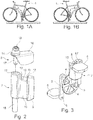
- a bicycle 1 is shown locked to an anti-theft device 2 according to the invention, by means of its right crank, while on the figure 1B a bicycle 1 is locked to an anti-theft device 2 according to the invention, by means of its left crank.
- a bottom bracket crank comprises a crank body 3 with a first end connected to a bottom bracket axle 4 and a second end connected to an axle 5 of a pedal 6.
- the anti-theft device 2 according to the invention for a bicycle comprises a first anti-theft part 7 and a second anti-theft part 8.
- the first anti-theft part 7 is here in the form of a one-piece assembly 9, having a front face with a housing 10, here in the form of a groove 10.
- a right pedal crank is placed in the housing 10. More precisely, the crank body 3 is engaged flat in abutment in the groove 10 when a user of the bicycle 1 directs the right crank arm upwards.
- the first anti-theft part 7 has a top face 11 serving as a bearing surface 11 for the pedal 6, when the bottom bracket crank is in the groove 10.
- the first anti-theft part 7 also has on the top face 11 a retaining means 12, here shown in the form of a U-shaped jumper 12 with the base of the U coincident with the bearing surface 11.
- This retaining means 12 is intended to hold the bicycle 1 stably in an upright position when the axis 5 of the pedal 6, on the figure 3 the pedal 6 on the right is positioned in the U of the jumper 12.
- the U of the jumper 12 also has bearing faces 12 ', visible on the figure 3 and on the figure 5B , intended to prevent the pedal 6 from tilting away from the first anti-theft part 7 and to keep the bicycle 1 in an upright position pending the installation of the second anti-theft part 8.
- the dimensions of the opening of the U are chosen so as to be greater than the diameter of the axis 5 of pedal 6 and less than the widths of the pedals of the usual bicycles in order to guarantee the compatibility of the anti-theft device 2 with the vast majority of bicycles.
- the first anti-theft part 7 here has an orifice 13 extending into the one-piece body 9 from the bearing surface 11.
- This orifice 13 is a lock receiver 13 intended to cooperate with a locking system of the second anti-theft part 8 as will be explained below.
- the first anti-theft part 7 may be secured to a frame fixed to the ground or to any construction intended to receive the bicycle 1. Here, it is secured to a stud 15 which may for example extend perpendicularly to the ground.
- the second anti-theft part 8 is presented here in the form of a U-shaped cover plate 16 with a base and two branches (as visible on the figure 5A ), and a locking system 14.
- a lock finger 17 extends perpendicularly from one face of the base of the U-section between the branches, while a lock 18 is arranged on the other face of the base of the U-section.
- the second anti-theft part 8 is intended to come over the first anti-theft part 7 so as to lock the bottom bracket crank in the first anti-theft part 7.
- the locking is effected by cooperation between the locking system 14 of the second anti-theft part 8 with here its lock finger 17 which is inserted according to the arrow F into the lock receiver 13 of the first anti-theft part 7.
- one of the branches of the U-shaped cover plate 16 covers the second end of the crank body 3 and the axis 5 of the pedal 6.
- the second anti-theft part 8 cannot rotate around the latch finger 17.
- the anti-theft property of the device is improved.
- the second anti-theft part 8 may be in the form of an L-shaped cover plate 16 'with a base and a branch, the base carrying the lock finger 17 and the latch 18.
- the branch of the cover plate 16 ' covers the second end of the crank body 3 and the axis 5 of the pedal 6 with the same advantages as described above, in particular to block the accesses to the axis 5 of the pedal 6 so as to prevent its removal.
- Additional rotation locking means can be arranged on the second anti-theft part 8 with the L-shaped cover plate 16 'so that the second anti-theft part 8 in the locked position cannot rotate around the finger lock 17.
- the figures 6A and 6B illustrate another embodiment of the invention, in which the first anti-theft part 7 is secured to a stud which extends perpendicularly from the ground but via an anchoring point inclined at an angle ⁇ with respect to the stud, that can go up to 30 °.
- This inclination of the anti-theft device 2 has the advantage that accessibility to the anti-theft device 2 is reduced because the anti-theft device 2 is even closer to the frame of the bicycle 1 than on the figures 1A and 1B .
- the first anti-theft part 7 of the anti-theft device 2 does not include a moving part and is therefore of simplified structure compared to the state of the art.
Landscapes
- Engineering & Computer Science (AREA)
- Mechanical Engineering (AREA)
- Lock And Its Accessories (AREA)
Claims (10)
- Diebstahlsicherung (2) für Fahrrad (1), wobei das Fahrrad eine Pedaltretkurbel umfasst, die einen Kurbelkorpus (3) mit einem mit einer Pedalachse (4) verbundenen ersten Ende und einem mit einer Achse (5) einer Pedale (6) verbundenen zweiten Ende umfasst, wobei die Diebstahlsicherung (2) ein zur Festlegung am Boden bestimmtes erstes Diebstahlsicherungsteil (7) mit einer Aufnahme (10), in welche die Pedaltretkurbel platzierbar ist, und ein zweites Diebstahlsicherungsteil (8), das einen entfernbaren Riegel bildet, der dazu bestimmt ist, das erste Diebstahlsicherungsteil (7) derart zu bedecken, dass die Pedaltretkurbel in dem ersten Diebstahlsicherungsteil (7) verriegelt ist, umfasst, wobei die Aufnahme (10) auf einer Stirnseite des ersten Diebstahlsicherungsteils (7) ausgebildet ist und dadurch gekennzeichnet ist,
dass die Aufnahme (10) eine Kerbe ist, in die der Kurbelkorpus (3) flach anschlagend einsetzbar ist, wenn die Pedaltretkurbel nach oben orientiert ist, und
dass das zweite Diebstahlsicherungsteil (8) ausgebildet ist, um das zweite Ende des Kurbelkorpus (3) und die Achse (5) der Pedale (6) zu bedecken, wenn der Kurbelkorpus (3) in die Kerbe eingesetzt ist. - Diebstahlsicherung (2) nach Anspruch 1, dadurch gekennzeichnet, dass das erste Diebstahlsicherungsteil (7) in der Gestalt einer einteiligen Baueinheit (9) vorgesehen ist, umfassend auf der Stirnseite die Kerbe und auf einer Oberseite eine für die Pedale (6) bestimmte Stützfläche (11) und ein Haltemittel (12), das für die Achse (5) der Pedale (6) bestimmt ist, um das Fahrrad (1) in aufrechter Position zu halten.
- Diebstahlsicherung (2) nach Anspruch 2, dadurch gekennzeichnet, dass das Haltemittel (12) ein U-förmiger Reiter ist, bei dem die Basis des U mit der Stützfläche (11) zusammenfällt.
- Diebstahlsicherung (2) nach Anspruch 2, dadurch gekennzeichnet, dass die einteilige Baueinheit (9) des ersten Diebstahlsicherungsteils (7) eine Aufnahme für einen Riegel (13) umfasst, die dazu bestimmt ist, mit dem Riegel des zweiten Diebstahlsicherungsteils (8) zusammenzuwirken.
- Diebstahlsicherung (2) nach Anspruch 4, dadurch gekennzeichnet, dass die Aufnahme des Riegels (13) eine Öffnung ist, die sich in den einteiligen Korpus (9) ausgehend von der Stützfläche (11) erstreckt.
- Diebstahlsicherung (2) nach einem der vorhergehenden Ansprüche,
dadurch gekennzeichnet, dass das zweite Diebstahlsicherungsteil (8) die Gestalt einer Abdeckplatte (16) mit einem U-Profil derart aufweist, dass wenn das zweite Diebstahlsicherungsteil (8) die Pedaltretkurbel verriegelt, die Basis des U-Profils die Stützfläche (11) des ersten Diebstahlsicherungsteils (7) bedeckt, wobei die Schenkel des U-Profils die Zugänge zu der Achse (5) der Pedale (6) bedecken. - Diebstahlsicherung (2) nach Anspruch 6, dadurch gekennzeichnet, dass der Riegel des zweiten Diebstahlsicherungsteils (8) ferner einen Riegelzapfen (17) umfasst, der sich quer ausgehend von der Basis des U-Profils zwischen den Schenkeln des U-Profils erstreckt und der dazu bestimmt ist, in die Aufnahme des Riegels (13) des ersten Diebstahlsicherungsteils (7) einzudringen.
- Diebstahlsicherung (2) nach einem der Ansprüche 1 bis 5, dadurch gekennzeichnet, dass das zweite Diebstahlsicherungsteil (8) die Gestalt einer Abdeckplatte (16') mit einem L-Profil derart aufweist, dass wenn das zweite Diebstahlsicherungsteil (8) die Pedaltretkurbel verriegelt, die Basis des L-Profils die Stützfläche (11) des ersten Diebstahlsicherungsteils (7) bedeckt, wobei der Schenkel des L-Profils den Zugang zu der Achse (5) der Pedale (6) bedeckt.
- Diebstahlsicherung (2) nach Anspruch 8, dadurch gekennzeichnet, dass der Riegel des zweiten Diebstahlsicherungsteils (8) ferner einen Riegelzapfen (17) umfasst, der sich quer ausgehend von der Basis des L-Profils entlang des Schenkels des L-Profils erstreckt und der dazu bestimmt ist, in die Aufnahme des Riegels (13) des ersten Diebstahlsicherungsteils (7) einzudringen.
- Diebstahlsicherung (2) nach einem der vorhergehenden Ansprüche, dadurch gekennzeichnet, dass das erste Diebstahlsicherungsteil (7) dazu bestimmt ist, an einem am Boden befestigten Gestell oder an jeder Konstruktion zur Aufnahme des Fahrrads (1) befestigt zu werden.
Applications Claiming Priority (1)
| Application Number | Priority Date | Filing Date | Title |
|---|---|---|---|
| FR1852999A FR3079808B1 (fr) | 2018-04-06 | 2018-04-06 | Dispositif antivol pour bicyclette |
Publications (2)
| Publication Number | Publication Date |
|---|---|
| EP3549849A1 EP3549849A1 (de) | 2019-10-09 |
| EP3549849B1 true EP3549849B1 (de) | 2020-08-26 |
Family
ID=63014686
Family Applications (1)
| Application Number | Title | Priority Date | Filing Date |
|---|---|---|---|
| EP19166640.3A Active EP3549849B1 (de) | 2018-04-06 | 2019-04-01 | Diebstahlsicherung für fahrrad |
Country Status (2)
| Country | Link |
|---|---|
| EP (1) | EP3549849B1 (de) |
| FR (1) | FR3079808B1 (de) |
Families Citing this family (3)
| Publication number | Priority date | Publication date | Assignee | Title |
|---|---|---|---|---|
| WO2021260066A1 (en) * | 2020-06-25 | 2021-12-30 | Brian Ellison | Bicycle parking and locking station |
| FR3144103B1 (fr) | 2022-12-21 | 2025-01-10 | Bikeslot | Dispositif antivol, notamment pour véhicule à pédalier |
| CN116691886B (zh) * | 2023-07-11 | 2026-02-17 | 广东球德健康科技有限公司 | 一种防盗电动助力自行车 |
Citations (1)
| Publication number | Priority date | Publication date | Assignee | Title |
|---|---|---|---|---|
| GB2544736A (en) * | 2015-11-23 | 2017-05-31 | Cyclepods Ltd | Bicycle storage apparatus |
Family Cites Families (2)
| Publication number | Priority date | Publication date | Assignee | Title |
|---|---|---|---|---|
| GB9215096D0 (en) * | 1992-07-16 | 1992-08-26 | Smith Gordon | Bikelox |
| US9096182B1 (en) * | 2013-08-06 | 2015-08-04 | Allfab, Inc. | Bicycle rack for a vehicle |
-
2018
- 2018-04-06 FR FR1852999A patent/FR3079808B1/fr not_active Expired - Fee Related
-
2019
- 2019-04-01 EP EP19166640.3A patent/EP3549849B1/de active Active
Patent Citations (1)
| Publication number | Priority date | Publication date | Assignee | Title |
|---|---|---|---|---|
| GB2544736A (en) * | 2015-11-23 | 2017-05-31 | Cyclepods Ltd | Bicycle storage apparatus |
Also Published As
| Publication number | Publication date |
|---|---|
| FR3079808A1 (fr) | 2019-10-11 |
| FR3079808B1 (fr) | 2020-08-28 |
| EP3549849A1 (de) | 2019-10-09 |
Similar Documents
| Publication | Publication Date | Title |
|---|---|---|
| EP3549849B1 (de) | Diebstahlsicherung für fahrrad | |
| FR2938817A1 (fr) | Systeme de stockage et de verrouillage de cycles | |
| EP1820721A1 (de) | Automatisches System zur Speicherung von Zyklen, Zyklus für ein solches System und Sperrvorrichtung für einen solchen Zyklus | |
| FR2970233A1 (fr) | Potence de velo pouvant etre liberee en tout ou partie de son pouvoir directionnel | |
| EP1965676B1 (de) | Vorrichtung zur positionierung und halterung eines notschlüssels | |
| FR3046401A1 (fr) | Cadre de bicyclette a assistance electrique | |
| EP1655214B1 (de) | Antidiebstahlvorrichtung für ein Fahrrad und ein Fahrrad mit solcher Vorrichtung | |
| FR2978417A1 (fr) | Vehicule repliable, par exemple du type trottinette | |
| EP2186714B1 (de) | Vorrichtung und System zum Verschließen von Selbstbedienungs-Fahrrädern | |
| FR3027330A1 (fr) | Terminal de paiement mobile comprenant une fonction de deverrouillage embarquee | |
| EP2754586B1 (de) | Verstauungselement für den Stauraum eines Reserverads eines Kraftfahrzeugs | |
| EP1409333A1 (de) | Fahrradständer | |
| FR2947237A1 (fr) | Cycle equipe d'une direction a fourche | |
| EP1093430B1 (de) | Schlossvorrichtung, insbesondere für zweiradfahrzeuge | |
| FR2861683A1 (fr) | Systeme d'antivol pour vehicule a deux roues de type scooter | |
| EP3409996B1 (de) | Adapter zur befestigung eines elektronischen zahlungsterminals auf einer halterung | |
| FR3049922B1 (fr) | Vehicule terrestre destine a un usage en libre service | |
| FR2867746A1 (fr) | Borne antivol pour le stationnement des deux roues | |
| FR3082822A1 (fr) | Dispositif de verrouillage d'un cycle sur une borne receptrice, cycle et borne receptrice comprenant ledit dispositif de verrouillage, et systeme automatique de stockage de cycles | |
| FR2672632A1 (fr) | Dispositif antivol de semi-remorque. | |
| FR3057512A1 (fr) | Support de velos escamotable sur attelage de vehicule | |
| FR3050170A1 (fr) | Vehicule repliable, par exemple du type trottinette,avec systeme de verrouillage | |
| EP2833331B1 (de) | Verriegelungsmechanismus zum Aufbewahren, insbesondere von Selbstbedienungseinkaufswagen | |
| FR3107547A1 (fr) | Moyen de demarrage comportant un capot de cle et vehicule equipe d’un tel moyen | |
| FR2782976A1 (fr) | Dispositif antivol a double anse, notamment pour vehicules a deux roues |
Legal Events
| Date | Code | Title | Description |
|---|---|---|---|
| PUAI | Public reference made under article 153(3) epc to a published international application that has entered the european phase |
Free format text: ORIGINAL CODE: 0009012 |
|
| STAA | Information on the status of an ep patent application or granted ep patent |
Free format text: STATUS: THE APPLICATION HAS BEEN PUBLISHED |
|
| AK | Designated contracting states |
Kind code of ref document: A1 Designated state(s): AL AT BE BG CH CY CZ DE DK EE ES FI FR GB GR HR HU IE IS IT LI LT LU LV MC MK MT NL NO PL PT RO RS SE SI SK SM TR |
|
| AX | Request for extension of the european patent |
Extension state: BA ME |
|
| RIC1 | Information provided on ipc code assigned before grant |
Ipc: B62H 3/10 20060101ALI20190918BHEP Ipc: B62H 1/08 20060101AFI20190918BHEP Ipc: B62H 5/10 20060101ALI20190918BHEP |
|
| STAA | Information on the status of an ep patent application or granted ep patent |
Free format text: STATUS: REQUEST FOR EXAMINATION WAS MADE |
|
| 17P | Request for examination filed |
Effective date: 20191218 |
|
| RBV | Designated contracting states (corrected) |
Designated state(s): AL AT BE BG CH CY CZ DE DK EE ES FI FR GB GR HR HU IE IS IT LI LT LU LV MC MK MT NL NO PL PT RO RS SE SI SK SM TR |
|
| GRAP | Despatch of communication of intention to grant a patent |
Free format text: ORIGINAL CODE: EPIDOSNIGR1 |
|
| STAA | Information on the status of an ep patent application or granted ep patent |
Free format text: STATUS: GRANT OF PATENT IS INTENDED |
|
| INTG | Intention to grant announced |
Effective date: 20200428 |
|
| GRAS | Grant fee paid |
Free format text: ORIGINAL CODE: EPIDOSNIGR3 |
|
| GRAA | (expected) grant |
Free format text: ORIGINAL CODE: 0009210 |
|
| STAA | Information on the status of an ep patent application or granted ep patent |
Free format text: STATUS: THE PATENT HAS BEEN GRANTED |
|
| AK | Designated contracting states |
Kind code of ref document: B1 Designated state(s): AL AT BE BG CH CY CZ DE DK EE ES FI FR GB GR HR HU IE IS IT LI LT LU LV MC MK MT NL NO PL PT RO RS SE SI SK SM TR |
|
| REG | Reference to a national code |
Ref country code: GB Ref legal event code: FG4D Free format text: NOT ENGLISH |
|
| REG | Reference to a national code |
Ref country code: CH Ref legal event code: EP |
|
| REG | Reference to a national code |
Ref country code: AT Ref legal event code: REF Ref document number: 1306112 Country of ref document: AT Kind code of ref document: T Effective date: 20200915 |
|
| REG | Reference to a national code |
Ref country code: IE Ref legal event code: FG4D Free format text: LANGUAGE OF EP DOCUMENT: FRENCH |
|
| REG | Reference to a national code |
Ref country code: DE Ref legal event code: R096 Ref document number: 602019000539 Country of ref document: DE |
|
| REG | Reference to a national code |
Ref country code: LT Ref legal event code: MG4D |
|
| PG25 | Lapsed in a contracting state [announced via postgrant information from national office to epo] |
Ref country code: PT Free format text: LAPSE BECAUSE OF FAILURE TO SUBMIT A TRANSLATION OF THE DESCRIPTION OR TO PAY THE FEE WITHIN THE PRESCRIBED TIME-LIMIT Effective date: 20201228 Ref country code: GR Free format text: LAPSE BECAUSE OF FAILURE TO SUBMIT A TRANSLATION OF THE DESCRIPTION OR TO PAY THE FEE WITHIN THE PRESCRIBED TIME-LIMIT Effective date: 20201127 Ref country code: BG Free format text: LAPSE BECAUSE OF FAILURE TO SUBMIT A TRANSLATION OF THE DESCRIPTION OR TO PAY THE FEE WITHIN THE PRESCRIBED TIME-LIMIT Effective date: 20201126 Ref country code: NO Free format text: LAPSE BECAUSE OF FAILURE TO SUBMIT A TRANSLATION OF THE DESCRIPTION OR TO PAY THE FEE WITHIN THE PRESCRIBED TIME-LIMIT Effective date: 20201126 Ref country code: FI Free format text: LAPSE BECAUSE OF FAILURE TO SUBMIT A TRANSLATION OF THE DESCRIPTION OR TO PAY THE FEE WITHIN THE PRESCRIBED TIME-LIMIT Effective date: 20200826 Ref country code: LT Free format text: LAPSE BECAUSE OF FAILURE TO SUBMIT A TRANSLATION OF THE DESCRIPTION OR TO PAY THE FEE WITHIN THE PRESCRIBED TIME-LIMIT Effective date: 20200826 Ref country code: SE Free format text: LAPSE BECAUSE OF FAILURE TO SUBMIT A TRANSLATION OF THE DESCRIPTION OR TO PAY THE FEE WITHIN THE PRESCRIBED TIME-LIMIT Effective date: 20200826 Ref country code: HR Free format text: LAPSE BECAUSE OF FAILURE TO SUBMIT A TRANSLATION OF THE DESCRIPTION OR TO PAY THE FEE WITHIN THE PRESCRIBED TIME-LIMIT Effective date: 20200826 |
|
| REG | Reference to a national code |
Ref country code: NL Ref legal event code: MP Effective date: 20200826 |
|
| REG | Reference to a national code |
Ref country code: AT Ref legal event code: MK05 Ref document number: 1306112 Country of ref document: AT Kind code of ref document: T Effective date: 20200826 |
|
| PG25 | Lapsed in a contracting state [announced via postgrant information from national office to epo] |
Ref country code: LV Free format text: LAPSE BECAUSE OF FAILURE TO SUBMIT A TRANSLATION OF THE DESCRIPTION OR TO PAY THE FEE WITHIN THE PRESCRIBED TIME-LIMIT Effective date: 20200826 Ref country code: PL Free format text: LAPSE BECAUSE OF FAILURE TO SUBMIT A TRANSLATION OF THE DESCRIPTION OR TO PAY THE FEE WITHIN THE PRESCRIBED TIME-LIMIT Effective date: 20200826 Ref country code: RS Free format text: LAPSE BECAUSE OF FAILURE TO SUBMIT A TRANSLATION OF THE DESCRIPTION OR TO PAY THE FEE WITHIN THE PRESCRIBED TIME-LIMIT Effective date: 20200826 Ref country code: NL Free format text: LAPSE BECAUSE OF FAILURE TO SUBMIT A TRANSLATION OF THE DESCRIPTION OR TO PAY THE FEE WITHIN THE PRESCRIBED TIME-LIMIT Effective date: 20200826 Ref country code: IS Free format text: LAPSE BECAUSE OF FAILURE TO SUBMIT A TRANSLATION OF THE DESCRIPTION OR TO PAY THE FEE WITHIN THE PRESCRIBED TIME-LIMIT Effective date: 20201226 |
|
| PG25 | Lapsed in a contracting state [announced via postgrant information from national office to epo] |
Ref country code: SM Free format text: LAPSE BECAUSE OF FAILURE TO SUBMIT A TRANSLATION OF THE DESCRIPTION OR TO PAY THE FEE WITHIN THE PRESCRIBED TIME-LIMIT Effective date: 20200826 Ref country code: EE Free format text: LAPSE BECAUSE OF FAILURE TO SUBMIT A TRANSLATION OF THE DESCRIPTION OR TO PAY THE FEE WITHIN THE PRESCRIBED TIME-LIMIT Effective date: 20200826 Ref country code: RO Free format text: LAPSE BECAUSE OF FAILURE TO SUBMIT A TRANSLATION OF THE DESCRIPTION OR TO PAY THE FEE WITHIN THE PRESCRIBED TIME-LIMIT Effective date: 20200826 Ref country code: DK Free format text: LAPSE BECAUSE OF FAILURE TO SUBMIT A TRANSLATION OF THE DESCRIPTION OR TO PAY THE FEE WITHIN THE PRESCRIBED TIME-LIMIT Effective date: 20200826 Ref country code: CZ Free format text: LAPSE BECAUSE OF FAILURE TO SUBMIT A TRANSLATION OF THE DESCRIPTION OR TO PAY THE FEE WITHIN THE PRESCRIBED TIME-LIMIT Effective date: 20200826 |
|
| REG | Reference to a national code |
Ref country code: DE Ref legal event code: R097 Ref document number: 602019000539 Country of ref document: DE |
|
| PG25 | Lapsed in a contracting state [announced via postgrant information from national office to epo] |
Ref country code: ES Free format text: LAPSE BECAUSE OF FAILURE TO SUBMIT A TRANSLATION OF THE DESCRIPTION OR TO PAY THE FEE WITHIN THE PRESCRIBED TIME-LIMIT Effective date: 20200826 Ref country code: AL Free format text: LAPSE BECAUSE OF FAILURE TO SUBMIT A TRANSLATION OF THE DESCRIPTION OR TO PAY THE FEE WITHIN THE PRESCRIBED TIME-LIMIT Effective date: 20200826 Ref country code: AT Free format text: LAPSE BECAUSE OF FAILURE TO SUBMIT A TRANSLATION OF THE DESCRIPTION OR TO PAY THE FEE WITHIN THE PRESCRIBED TIME-LIMIT Effective date: 20200826 |
|
| PG25 | Lapsed in a contracting state [announced via postgrant information from national office to epo] |
Ref country code: SK Free format text: LAPSE BECAUSE OF FAILURE TO SUBMIT A TRANSLATION OF THE DESCRIPTION OR TO PAY THE FEE WITHIN THE PRESCRIBED TIME-LIMIT Effective date: 20200826 |
|
| PLBE | No opposition filed within time limit |
Free format text: ORIGINAL CODE: 0009261 |
|
| STAA | Information on the status of an ep patent application or granted ep patent |
Free format text: STATUS: NO OPPOSITION FILED WITHIN TIME LIMIT |
|
| PG25 | Lapsed in a contracting state [announced via postgrant information from national office to epo] |
Ref country code: IT Free format text: LAPSE BECAUSE OF FAILURE TO SUBMIT A TRANSLATION OF THE DESCRIPTION OR TO PAY THE FEE WITHIN THE PRESCRIBED TIME-LIMIT Effective date: 20200826 |
|
| 26N | No opposition filed |
Effective date: 20210527 |
|
| PG25 | Lapsed in a contracting state [announced via postgrant information from national office to epo] |
Ref country code: SI Free format text: LAPSE BECAUSE OF FAILURE TO SUBMIT A TRANSLATION OF THE DESCRIPTION OR TO PAY THE FEE WITHIN THE PRESCRIBED TIME-LIMIT Effective date: 20200826 |
|
| PG25 | Lapsed in a contracting state [announced via postgrant information from national office to epo] |
Ref country code: MC Free format text: LAPSE BECAUSE OF FAILURE TO SUBMIT A TRANSLATION OF THE DESCRIPTION OR TO PAY THE FEE WITHIN THE PRESCRIBED TIME-LIMIT Effective date: 20200826 |
|
| PG25 | Lapsed in a contracting state [announced via postgrant information from national office to epo] |
Ref country code: LU Free format text: LAPSE BECAUSE OF NON-PAYMENT OF DUE FEES Effective date: 20210401 |
|
| PG25 | Lapsed in a contracting state [announced via postgrant information from national office to epo] |
Ref country code: IE Free format text: LAPSE BECAUSE OF NON-PAYMENT OF DUE FEES Effective date: 20210401 |
|
| PG25 | Lapsed in a contracting state [announced via postgrant information from national office to epo] |
Ref country code: IS Free format text: LAPSE BECAUSE OF FAILURE TO SUBMIT A TRANSLATION OF THE DESCRIPTION OR TO PAY THE FEE WITHIN THE PRESCRIBED TIME-LIMIT Effective date: 20201226 |
|
| REG | Reference to a national code |
Ref country code: CH Ref legal event code: PL |
|
| PG25 | Lapsed in a contracting state [announced via postgrant information from national office to epo] |
Ref country code: LI Free format text: LAPSE BECAUSE OF NON-PAYMENT OF DUE FEES Effective date: 20220430 Ref country code: CH Free format text: LAPSE BECAUSE OF NON-PAYMENT OF DUE FEES Effective date: 20220430 |
|
| REG | Reference to a national code |
Ref country code: DE Ref legal event code: R081 Ref document number: 602019000539 Country of ref document: DE Owner name: BIKESLOT, FR Free format text: FORMER OWNER: DESIGN ET MECANIQUE, MONTAUD, FR Ref country code: DE Ref legal event code: R082 Ref document number: 602019000539 Country of ref document: DE Representative=s name: DENNEMEYER & ASSOCIATES S.A., DE Ref country code: DE Ref legal event code: R082 Ref document number: 602019000539 Country of ref document: DE Representative=s name: DENNEMEYER & ASSOCIATES RECHTSANWALTSGESELLSCH, DE |
|
| PG25 | Lapsed in a contracting state [announced via postgrant information from national office to epo] |
Ref country code: CY Free format text: LAPSE BECAUSE OF FAILURE TO SUBMIT A TRANSLATION OF THE DESCRIPTION OR TO PAY THE FEE WITHIN THE PRESCRIBED TIME-LIMIT Effective date: 20200826 |
|
| REG | Reference to a national code |
Ref country code: GB Ref legal event code: 732E Free format text: REGISTERED BETWEEN 20230622 AND 20230628 |
|
| PG25 | Lapsed in a contracting state [announced via postgrant information from national office to epo] |
Ref country code: HU Free format text: LAPSE BECAUSE OF FAILURE TO SUBMIT A TRANSLATION OF THE DESCRIPTION OR TO PAY THE FEE WITHIN THE PRESCRIBED TIME-LIMIT; INVALID AB INITIO Effective date: 20190401 |
|
| REG | Reference to a national code |
Ref country code: BE Ref legal event code: PD Owner name: BIKESLOT; FR Free format text: DETAILS ASSIGNMENT: CHANGE OF OWNER(S), ASSIGNMENT; FORMER OWNER NAME: PRUGNEAU PHILIPPE Effective date: 20230626 |
|
| PG25 | Lapsed in a contracting state [announced via postgrant information from national office to epo] |
Ref country code: MK Free format text: LAPSE BECAUSE OF FAILURE TO SUBMIT A TRANSLATION OF THE DESCRIPTION OR TO PAY THE FEE WITHIN THE PRESCRIBED TIME-LIMIT Effective date: 20200826 |
|
| PG25 | Lapsed in a contracting state [announced via postgrant information from national office to epo] |
Ref country code: MT Free format text: LAPSE BECAUSE OF FAILURE TO SUBMIT A TRANSLATION OF THE DESCRIPTION OR TO PAY THE FEE WITHIN THE PRESCRIBED TIME-LIMIT Effective date: 20200826 |
|
| REG | Reference to a national code |
Ref country code: DE Ref legal event code: R082 Ref document number: 602019000539 Country of ref document: DE Representative=s name: DENNEMEYER & ASSOCIATES RECHTSANWALTSGESELLSCH, DE |
|
| PGFP | Annual fee paid to national office [announced via postgrant information from national office to epo] |
Ref country code: DE Payment date: 20250422 Year of fee payment: 7 |
|
| PGFP | Annual fee paid to national office [announced via postgrant information from national office to epo] |
Ref country code: GB Payment date: 20250423 Year of fee payment: 7 |
|
| PGFP | Annual fee paid to national office [announced via postgrant information from national office to epo] |
Ref country code: BE Payment date: 20250418 Year of fee payment: 7 |
|
| PGFP | Annual fee paid to national office [announced via postgrant information from national office to epo] |
Ref country code: FR Payment date: 20250425 Year of fee payment: 7 |
|
| PG25 | Lapsed in a contracting state [announced via postgrant information from national office to epo] |
Ref country code: TR Free format text: LAPSE BECAUSE OF FAILURE TO SUBMIT A TRANSLATION OF THE DESCRIPTION OR TO PAY THE FEE WITHIN THE PRESCRIBED TIME-LIMIT Effective date: 20200826 |