EP2186714B1 - Vorrichtung und System zum Verschließen von Selbstbedienungs-Fahrrädern - Google Patents
Vorrichtung und System zum Verschließen von Selbstbedienungs-Fahrrädern Download PDFInfo
- Publication number
- EP2186714B1 EP2186714B1 EP09290861A EP09290861A EP2186714B1 EP 2186714 B1 EP2186714 B1 EP 2186714B1 EP 09290861 A EP09290861 A EP 09290861A EP 09290861 A EP09290861 A EP 09290861A EP 2186714 B1 EP2186714 B1 EP 2186714B1
- Authority
- EP
- European Patent Office
- Prior art keywords
- locking
- bicycle
- fixed
- embedded
- locking element
- Prior art date
- Legal status (The legal status is an assumption and is not a legal conclusion. Google has not performed a legal analysis and makes no representation as to the accuracy of the status listed.)
- Active
Links
- 238000000034 method Methods 0.000 claims abstract description 12
- 238000006073 displacement reaction Methods 0.000 claims 2
- 238000009434 installation Methods 0.000 description 3
- 230000006378 damage Effects 0.000 description 2
- 230000008961 swelling Effects 0.000 description 2
- 230000001351 cycling effect Effects 0.000 description 1
- 238000000280 densification Methods 0.000 description 1
- 238000000151 deposition Methods 0.000 description 1
- 239000002184 metal Substances 0.000 description 1
- 230000036515 potency Effects 0.000 description 1
Images




Classifications
-
- G—PHYSICS
- G07—CHECKING-DEVICES
- G07F—COIN-FREED OR LIKE APPARATUS
- G07F17/00—Coin-freed apparatus for hiring articles; Coin-freed facilities or services
- G07F17/10—Coin-freed apparatus for hiring articles; Coin-freed facilities or services for means for safe-keeping of property, left temporarily, e.g. by fastening the property
-
- B—PERFORMING OPERATIONS; TRANSPORTING
- B62—LAND VEHICLES FOR TRAVELLING OTHERWISE THAN ON RAILS
- B62H—CYCLE STANDS; SUPPORTS OR HOLDERS FOR PARKING OR STORING CYCLES; APPLIANCES PREVENTING OR INDICATING UNAUTHORIZED USE OR THEFT OF CYCLES; LOCKS INTEGRAL WITH CYCLES; DEVICES FOR LEARNING TO RIDE CYCLES
- B62H3/00—Separate supports or holders for parking or storing cycles
- B62H3/02—Separate supports or holders for parking or storing cycles involving means for gripping the cycle by the handlebars or by the upper part of the frame
-
- B—PERFORMING OPERATIONS; TRANSPORTING
- B62—LAND VEHICLES FOR TRAVELLING OTHERWISE THAN ON RAILS
- B62H—CYCLE STANDS; SUPPORTS OR HOLDERS FOR PARKING OR STORING CYCLES; APPLIANCES PREVENTING OR INDICATING UNAUTHORIZED USE OR THEFT OF CYCLES; LOCKS INTEGRAL WITH CYCLES; DEVICES FOR LEARNING TO RIDE CYCLES
- B62H5/00—Appliances preventing or indicating unauthorised use or theft of cycles; Locks integral with cycles
-
- B—PERFORMING OPERATIONS; TRANSPORTING
- B62—LAND VEHICLES FOR TRAVELLING OTHERWISE THAN ON RAILS
- B62H—CYCLE STANDS; SUPPORTS OR HOLDERS FOR PARKING OR STORING CYCLES; APPLIANCES PREVENTING OR INDICATING UNAUTHORIZED USE OR THEFT OF CYCLES; LOCKS INTEGRAL WITH CYCLES; DEVICES FOR LEARNING TO RIDE CYCLES
- B62H5/00—Appliances preventing or indicating unauthorised use or theft of cycles; Locks integral with cycles
- B62H5/20—Appliances preventing or indicating unauthorised use or theft of cycles; Locks integral with cycles indicating unauthorised use, e.g. acting on signalling devices
-
- B—PERFORMING OPERATIONS; TRANSPORTING
- B62—LAND VEHICLES FOR TRAVELLING OTHERWISE THAN ON RAILS
- B62H—CYCLE STANDS; SUPPORTS OR HOLDERS FOR PARKING OR STORING CYCLES; APPLIANCES PREVENTING OR INDICATING UNAUTHORIZED USE OR THEFT OF CYCLES; LOCKS INTEGRAL WITH CYCLES; DEVICES FOR LEARNING TO RIDE CYCLES
- B62H3/00—Separate supports or holders for parking or storing cycles
- B62H2003/005—Supports or holders associated with means for bike rental
Definitions
- the present invention relates to the field of bicycle lock devices and more particularly self-service rental bicycles.
- locking terminals are individually sealed to the roadway. They are electrically powered and connected to the network by cables housed in concrete underground girders. This type of access terminal has a cost of implementation important.
- the object of the present invention is to overcome one or more disadvantages of the prior art by providing a technical solution to a locking and unlocking system protecting against theft and controlling the borrowing and depositing of any type of series of bicycles or particular without changing the bike.
- the locking system comprises at least one fixed locking station and at least one locking element on board a bicycle having a steering system consisting of a bracket mounted sliding to a steering column, the stationary locking station being composed of at least one housing intended to receive the locking element on board a bicycle, characterized in that the locking station is composed of a tilting mechanism for retaining a bicycle in the housing at the on-board locking element and a radio-frequency transceiver, and in that the on-board locking element is clipped definitively around a bicycle element, a RFID component (Radio-Frequency Identification) consisting of at least one RF antenna (Radio Frequency) being arranged in the radio-frequency element. embedded lock, a wire of said antenna circling the locking member such that said antenna wire is cut off if the locking member is disassembled from the bicycle member.
- a RFID component Radio-Frequency Identification
- the onboard locking element has an inner surface whose geometry prevents the sliding of the onboard locking element along the bicycle element.
- the onboard locking element is placed in such a way that the height between the onboard locking element and the contact surface between the front wheel of the bicycle and the ground is substantially equal to the height between the tilting device of the locking station and the ground.
- the tilting mechanism is composed of a striker, pivotally mounted to the fixed locking station, with a geometry adapted so that the keeper pivots when the bicycle provided with the onboard locking element pushes into the housing of the fixed locking station and prevents the release of the bicycle equipped with the embedded locking element when the onboard locking element is fully engaged in the housing through a notch adapted to the dimension of the diameter of the element of embedded lock.
- the tilting mechanism is composed of two abutments placed symmetrically in a vertical plane, each abutment being pivotally mounted to the fixed locking station, each abutment having a spout turned towards the vertical plane adapted for the abutments to move apart. from one another by pivoting when the bicycle equipped with the on-board locking element pushes into the housing of the fixed station between the stops and so that they do not move apart when the bicycle equipped with the embedded locking element is locked, preventing the release of the bicycle provided with the embedded locking element, each stop having a geometry forming a housing adapted to the embedded locking element when the two stops are not spaced apart.
- the onboard locking element has a groove on its outer face oriented in a plane parallel to the movement of the bicycle whose width is substantially equal to the thickness of the striker and whose height relative to the ground is the as well as the height of the striker with respect to the ground added to a game taking into account at least inaccuracies of the ground, the swelling of the tires of the bicycles and the tolerances of installation of the locking system.
- the onboard locking element has a groove on its outer face oriented in a plane parallel to the movement of the bicycle whose width is substantially equal to the thickness of the stops and whose height relative to the ground is the same. that the height of the abutments with respect to the added ground of a game taking into account at least inaccuracies of the ground, the inflation of the tires of the bicycles and the tolerances of installation of the locking system.
- the keeper pivots when engaging a bicycle equipped with the onboard element fixed on the stem of a bicycle in the housing of the fixed locking station and the identification of the RFID component of the on-board locking element by the radio-frequency receiver-transmitter of the fixed locking station.
- the stops pivot during the engagement of a bicycle provided with the onboard element fixed on the stem of a bicycle in the housing of the fixed locking station and the identification of the RFID component of the on-board locking element by the radio-frequency receiver-transmitter of the fixed locking station.
- the rail has a rail for sliding the plurality of fixed locking stations along the rail, the fixed locking stations being electrically powered by a friction method.
- the posts of the support are able to contain power and network cables allowing the continuity of the supply and network cables of the rail in the support posts.
- the module is a locking system having a radiofrequency receiver-transmitter able to lock, for example, an electrical socket battery charging system of any type of self-service vehicles such as electric bikes, electric scooters or electric carts.
- Another object of the invention is to propose a locking method involving the system of the invention.
- the invention relates to a locking system consisting of at least one fixed locking station (2) and at least one onboard locking element (1) on a bicycle, the stationary locking station (2) being composed of at least one housing (3) for receiving the onboard locking element (1).
- the stationary locking station (2) is composed of a tilting mechanism (4) for retaining in the housing (3) a bicycle element at the level of the onboard locking element (1) and a transmitter. radio frequency receiver not shown.
- the element of the bicycle is, for example, a section of the bicycle stem, a section of the bicycle steering column or a section straddling the steering column and the bicycle stem, or a vertical tube attached to a bicycle. basket, or on the basket structure for a bike equipped with a handlebar basket, or on the bottom of the frame of the bike to the pedal, or to the gallows of the saddle of the bike.
- the onboard locking element (1) has a cylindrical or frustoconical shape of revolution permanently clipped around the element of the bicycle (5) along a clipping line (7).
- An RFID component consisting of at least one RF antenna (6) is disposed in the onboard locking element (1).
- An antenna wire (6) circumscribes the locking element such that the antenna wire (6) is cut off if the onboard locking element (1) is disassembled or destroyed.
- the onboard locking element (1) has an internal surface whose geometry prevents the sliding of the onboard locking element (1) along the element of the bicycle (5).
- the geometry of the inner surface of the onboard locking element (1) is adapted to the particular geometry of the mounting system of the stem (5) of the bicycle with the steering column (9), the stem (5) surmounted by a handlebar (8) being mounted telescopically in the steering column (9) and being fixed at a given position relative to the ground by means of a nut (10) surmounted by a cap (11), the steering column (9) being composed, in its lower part, of the fork holding the front wheel of the bicycle.
- the geometry of the inner surface of the onboard locking element (1) is adapted to the particular geometry of a section of the steering column (9) of the bicycle.
- the geometry of the inner surface of the onboard locking element (1) is adapted to the particular geometry of a section of the gallows (5) of the bicycle.
- the clipping line (7) of the onboard locking element is provided with a definitive clipping system.
- the antenna wire (6) is cut causing the final destruction of the antenna (6) and therefore the identification of the on-board locking element (1) by the transceiver of the fixed locking station (2) is impossible, thus preventing the use of the on-board locking element (1) for another bicycle .
- the clipping line of the embedded locking element (1) is an open groove.
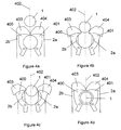
- the fixed locking station (2) is formed of two protuberances (2a, 2b), placed symmetrically according to a vertical plane (402), parallel to the ground, interconnected so that they form between them a housing (3) adapted to the curved surface of the embedded locking element (1) and the element cycling (5).
- a keeper (4) is rotatably mounted along an axis (2c) located at one of the two protuberances (2a) thereby forming a tilting mechanism.
- the pivot striker has a notch (4a) fitting to the curved surface of the embedded locking element (1) and located between two projections.
- a (4b) of the two projections occupies part of the housing (3).
- the onboard locking element (1) pushes the projection (4b) occupying in part the housing allowing the rotation of the striker (4) around its axis (2c).
- the other projection (4c) having the axis (2c) of rotation of the striker (4) advances in rotation so that the notch (4a) of the striker (4) surrounds the onboard locking element (1) clipped onto the bike element (5) as shown in Figure 2d.
- each abutment (400, 401) placed symmetrically in the vertical plane (402) of the protuberances (2a, 2b) of the fixed locking station (2), each abutment (400, 401) being pivotally mounted to the fixed locking station (2 ), each abutment (400, 401) having a spout (403, 404) facing the plane of symmetry (402), adapted so that the abutments (400, 401) deviate from one another by pivoting when a bicycle provided with the onboard locking element (1) engages by pushing in the housing (3) of the fixed station (2) between the stops (400, 401) and so that they do not move apart when the equipped with the onboard locking element (1) is locked, preventing the release of the bicycle provided with the onboard locking element (1), each stop (400, 401) having a geometry forming a housing adapted to the element onboard locking device (1) when the two stops (401, 402) are not separated.
- the onboard locking element (1) is placed in such a way that the height between the onboard locking element (1) and the contact between the front wheel of the bicycle and the ground is substantially equal to the height between the tilting device of the fixed locking station (2) and the added ground of a game taking into account at least the inaccuracies of the ground, the swelling of the tires bicycles and mounting tolerances of the locking system.
- This arrangement of the onboard locking element (1) on the bicycle allows a contact of the front wheel of the bike with the ground, with a game preventing the removal of the front wheel of the bicycle, thus preventing the theft of the bike (20) even if the handlebar is removed.
- the onboard locking element (1) has a groove (12) parallel to the ground around the onboard locking element (1).
- the plane containing this groove (12) is situated at the same height with respect to the ground as the plane where the striker or the stops are situated so that this height is substantially equal to the height between the lowest point of the front wheel of the bicycle and the plane containing the groove (12) added with a clearance taking into account at least inaccuracies of the ground, the inflation of the tires of the bicycles and the installation tolerances of the locking system.
- the rotation of the striker (4) or stops (400, 401) is allowed after identification of the RFID component of the onboard locking element (1) by the transceiver of the fixed locking station (2).
- the rotation of the striker (4) or stops (400, 401) is authorized after identification of the bicycle user by a badge.
- the rotation of the striker (4) or stops (400, 401) is motorized.
- the fixed locking station (2) is fixed among a plurality of fixed locking stations (2) regularly spaced along a rail (13).
- the beam (13) is embedded in two notches (17) located at the top of two posts (14).
- the rails are embedded in the notches (17) of the posts (14), the notch (17) is closed with a cap (15) adapted to the top of each post (14).
- the cap (15) is adapted to be locked on each post (14) by a locking system (16b, 16a) thus preventing the removal of the rails (13) without unlocking.
- the posts (14) are able to contain power cables passing through the rails (13) to feed the stationary locking positions (2).
- the posts (14) are furthermore capable of containing network cables making it possible to control the fixed locking stations (2).
- the posts (14) are thus able to ensure the continuity of the power supply and network cables (18) of the rail (13).
- the posts (14) are also able to allow the connection and disconnection of at least one module while providing mechanical protection of the connection of the module.
- a module is, for example, a locking system having at least one radiofrequency receiver-transmitter capable of locking an electrical plug of battery charging system of any type of vehicle such as electric bicycles, electric scooters or electric carts.
- the electrical outlet is locked and the power distribution is activated after recognition of an RFID tag by the transceiver of the module. It is then unlocked and the current distribution is disabled after recognition of the RFID badge by the transceiver of the module.
- the rail (13) has a rail on which slides a plurality of fixed locking stations (2) along the rail (13), the fixed locking stations (2) being electrically powered by a friction method.
- the figure 7 shows an exemplary embodiment of a locking station composed of four fixed locking stations (2) mounted on a rail (13) surmounting two posts (14) where a bicycle (20) is locked in each stationary locking station (2) ).
Landscapes
- Engineering & Computer Science (AREA)
- Mechanical Engineering (AREA)
- Physics & Mathematics (AREA)
- General Physics & Mathematics (AREA)
- Lock And Its Accessories (AREA)
- Transmitters (AREA)
Claims (15)
- Verriegelungssystem, das zusammengesetzt ist aus mindestens einer ortsfesten Verriegelungsstelle (2) und mindestens einem Verriegelungselement (1), das in ein Fahrrad eingebaut ist, das ein aus einer gleitend in einem Steuerrohr (9) montierten Lenkersäule (5) gebildetes Lenksystem aufweist, wobei die ortsfeste Verriegelungsstelle (2) aus mindestens einer Aufnahme (3) gebildet ist, die zum Aufnehmen des in das Fahrrad eingebauten Verriegelungselements (1) bestimmt ist,
dadurch gekennzeichnet, dass die ortsfeste Verriegelungsstelle (2) aus einem Schwenkmechanismus (4), der das Halten eines Fahrrades in der Aufnahme (3) auf der Höhe des eingebauten Verriegelungselements (1) ermöglicht, und aus einem Radiofrequenz-Sender-Empfänger zusammengesetzt ist,
und dass das eingebaute Verriegelungselement (1) fest um einen Teilabschnitt eines Elements des Fahrrades herumgeklammert ist, wobei eine aus mindestens einer RF-Antenne (6) (Radiofrequenz) bestehende RFID-Komponente (Radio-Frequenz-Identifikation) in dem eingebauten Verriegelungselement (1) angeordnet ist, wobei ein Anschlussdraht der Antenne (6) derart um das Verriegelungselement (1) herumverläuft, dass der Anschlussdraht der RF-Antenne (6) abgetrennt wird, wenn das Verriegelungselement (1) von dem Element des Fahrrades abmontiert wird. - Verriegelungssystem gemäß Anspruch 1, dadurch gekennzeichnet, dass das eingebaute Verriegelungselement (1) eine Innenfläche aufweist, deren Geometrie das Gleiten des Verriegelungselements (1) entlang dem Element des Fahrrades verhindert.
- Verriegelungssystem gemäß Anspruch 1, dadurch gekennzeichnet, dass das eingebaute Verriegelungselement (1) derart angeordnet ist, dass die Höhe zwischen dem eingebauten Verriegelungselement (1) und der Kontaktfläche zwischen dem Vorderrad des Fahrrades und dem Boden im Wesentlichen gleich der Höhe zwischen der Schwenkvorrichtung der Verriegelungsstelle und dem Boden ist.
- Verriegelungssystem gemäß Anspruch 1, dadurch gekennzeichnet, dass der Schwenkmechanismus aus einem Schließhaken (4) zusammengesetzt ist, der an der ortsfesten Verriegelungsstelle (2) drehbar gelagert ist, mit einer Geometrie, die angepaßt ist, damit der Schließhaken (4) sich dreht, wenn das mit dem eingebauten Verriegelungselement (1) ausgestattete Fahrrad durch Schieben mit der Aufnahme (3) der ortsfesten Verriegelungsstelle (2) in Eingriff gelangt, und das Freigeben des mit dem eingebauten Verriegelungselement (1) ausgestatteten Fahrrades verhindert, wenn das eingebaute Verriegelungselement (1) vollständig mit der Aufnahme (3) in Eingriff ist, dank einer Aussparung (4a), die sich an die Abmessung des Durchmessers des eingebauten Verriegelungselements (1) anpasst.
- Verriegelungssystem gemäß Anspruch 1, dadurch gekennzeichnet, dass der Schwenkmechanismus aus zwei Anschlägen (400, 401) zusammengesetzt ist, die entlang einer vertikalen Ebene (402) symmetrisch angeordnet sind, wobei jeder Anschlag (400, 401) an der ortsfesten Verriegelungsstelle (2) drehbar gelagert ist, wobei jeder Anschlag (400, 401) eine Spitze (403, 404) aufweist, die zu der vertikalen Ebene (402) hin ausgerichtet ist, die angepasst ist, damit die Anschläge (400, 401) durch Drehen auseinandergespreizt werden, wenn das mit dem eingebauten Verriegelungssystem (1) ausgestattete Fahrrad durch Schieben mit der Aufnahme (3) der ortsfesten Verriegelungsstelle (2) zwischen den Anschlagen (400, 401) in Eingriff gelangt, und damit sie nicht gespreizt werden, wenn das mit dem eingebauten Verriegelungselement (1) ausgestattete Fahrrad verriegelt ist, wodurch das Freigeben des mit dem eingebauten Verriegelungselement (1) ausgestatteten Fahrrades verhindert wird, wobei jeder Anschlag (400, 401) eine Geometrie aufweist, die eine Aufnahme (3) ausbildet, die an das eingebaute Verriegelungselement (1) angepasst ist, wenn die zwei Anschläge (400, 401) nicht gespreizt sind.
- Verriegelungssystem gemäß Anspruch 4, dadurch gekennzeichnet, dass das eingebaute Verriegelungselement (1) an seiner Außenfläche eine Auskehlung (12) aufweist, die in einer Ebene parallel, zu der Verlagerung des Fahrrades ausgerichtet ist, deren Breite im Wesentlichen gleich der Dicke des Schließhakens (4) ist, und deren Höhe bezüglich des Bodens gleich wie die Höhe des Schließhakens (4) bezüglich des Bodens ist, zuzüglich eines Spiels unter Berücksichtigung zumindest der Unebenheiten des Bodens, der Füllung der Reifen der Fahrräder und der Einbautoleranzen des Verriegelungssystems.
- Verriegelungssystem gemäß Anspruch 5, dadurch gekennzeichnet, dass das eingebaute Verriegelungselement (1) an seiner Außenseite eine Auskehlung (12) aufweist, die in einer Ebene parallel zu der Verlagerung des Fahrrades ausgerichtet ist, deren Breite im Wesentlichen gleich der Dicke der Anschläge (400, 401) ist und deren Höhe bezüglich des Bodens gleich wie die Höhe der Anschläge (400, 401) bezüglich des Bodens ist, zuzüglich eines Spiels unter Berücksichtigung mindestens der Unebenheiten des Bodens, der Füllung der Reifen der Fahrräder und der Einbautoleranzen des Verriegelungssystems.
- Verriegelungssystem gemäß Anspruch 4, dadurch gekennzeichnet, dass sich der Schließhaken (4) beim Eingreifen eines mit dem an der Fahrrad-Lenkersäule (5) befestigten eingebauten Element (1) ausgestatteten Fahrrades in die Aufnahme (3) der ortsfesten Verriegelungsstelle (2) und beim Identifizieren der RFID-Komponente des eingebauten Verriegelungselements (1) durch den Sender-Empfänger der ortsfesten Verriegelungsstelle (2) dreht.
- Verriegelungssystem gemäß Anspruch 5, dadurch gekennzeichnet, dass sich die Anschläge (400, 401) beim Eingreifen eines mit dem an der Fahrrad-Lenkersäule (5) befestigten eingebauten Element (1) ausgestatteten Fahrrades in die Aufnahme (3) der festen Verriegelungsstelle (2) und beim Identifizieren der RFID-Komponente des eingebauten Verriegelungselements (1) durch den Sender-Empfänger der ortsfesten Verriegelungsstelle (2) drehen.
- Verriegelungssystem gemäß Anspruch 1, dadurch gekennzeichnet, dass die ortsfeste Verriegelungsstelle (2) an einer Stütze befestigt ist, die eine Mehrzahl von ortsfesten Verriegelungsstellen (2) aufweist, wobei die Stütze einer Mehrzahl von ortsfesten Verriegelungsstellen (2) zusammengesetzt ist aus mindestens:zwei Pfosten (14),einem Trägerbalken (13), an dem die Mehrzahl von ortsfesten Verriegelungsstellen (2) befestigt ist.
- Verriegelungssystem gemäß Anspruch 10, dadurch gekennzeichnet, dass der Trägerbalken (13) eine Schiene aufweist, die das Verschieben der Mehrzahl von ortsfesten Verriegelungsstellen (2) entlang dem Trägerbalken (13) ermöglicht, wobei die ortsfesten Verriegelungsstellen (2) durch einen Reibungsprozess mit Strom versorgt werden.
- Verriegelungssystem gemäß Anspruch 11, dadurch gekennzeichnet, dass die Pfosten (14) der Stütze geeignet sind, Versorgung- und Netzkabel (18) aufzunehmen, die das Weiterführen der Versorgungs- und Netzkabel (18) des Trägerbalkens (13) in den Stützpfosten (14) ermöglichen.
- Verriegelungssystem gemäß Anspruch 12, dadurch gekennzeichnet, dass das Modul ein Verriegelungssystem ist, das einen Radiofrequenz-Sender-Empfänger aufweiset, der geeignet ist, zum Beispiel einen elektrischen Anschluss für ein Batterie-Auflade-System für jede Art von Selbstbedienungsfahrzeugen, zum Beispiel Elektrofahrrädern, Elektrorollern oder Elektrohandwagen zu verriegeln.
- Verfahren zum Verriegeln eines Fahrrades mittels eines Verriegelungssystems gemäß den Ansprüchen 1 bis 13 an einer ortsfesten Verriegelungsstelle (2), die an einer eine Mehrzahl von ortsfesten Verriegelungsstellen (2) aufweisenden Stütze befestigt ist und eine Aufnahme (3), einen Schwenkmechanismus und einen Radiofrequenz-Sender-Empfänger aufweist, wobei das Fahrrad ein eingebautes Verriegelungselement (1) aufweist, das an jede der ortsfesten Verriegelungsstellen (2) anpassbar ist, wobei das eingebaute Verriegelungselement (1) eine RFID-Komponente aufweist, wobei das Verfahren dadurch gekennzeichnet ist, dass es aufweist:einen Schritt des In-Eingriff-Bringens des Fahrrades mit der Aufnahme (3) der ortsfesten Verriegelungsstelle (2) auf der Höhe des eingebauten Verriegelungselements (1),einen Schritt des Identifizierens der in dem eingebauten Verriegelungselement (1) angeordneten RFID-Komponente durch den Radiofrequenz-Sender-Empfänger in der ortsfesten Verriegelungsstelle (2),einen Schritt des Betätigens des Schwenkmechanismus,einen Schritt des Verriegelns des mit dem eingebauten Verriegelungselement (1) ausgestatteten Fahrrades an der ortsfesten Verriegelungsstelle (2).
- Verfahren gemäß Anspruch 14, dadurch gekennzeichnet, dass das Verfahren zum Verriegeln eines Fahrrades an einer ortsfesten Verriegelungsstelle (2) dadurch gekennzeichnet ist, dass es aufweist:einen Schritt des Identifizierens einer dem Besitzer des Fahrrades gehörenden besonderen Kennzeichnung durch den Radiofrequenz-Sender-Empfänger.
Applications Claiming Priority (1)
| Application Number | Priority Date | Filing Date | Title |
|---|---|---|---|
| FR0806379A FR2938496B1 (fr) | 2008-11-14 | 2008-11-14 | Dispositif et systeme de verrouillage de velos en libre service |
Publications (2)
| Publication Number | Publication Date |
|---|---|
| EP2186714A1 EP2186714A1 (de) | 2010-05-19 |
| EP2186714B1 true EP2186714B1 (de) | 2011-06-29 |
Family
ID=40785416
Family Applications (1)
| Application Number | Title | Priority Date | Filing Date |
|---|---|---|---|
| EP09290861A Active EP2186714B1 (de) | 2008-11-14 | 2009-11-13 | Vorrichtung und System zum Verschließen von Selbstbedienungs-Fahrrädern |
Country Status (3)
| Country | Link |
|---|---|
| EP (1) | EP2186714B1 (de) |
| AT (1) | ATE514621T1 (de) |
| FR (1) | FR2938496B1 (de) |
Families Citing this family (4)
| Publication number | Priority date | Publication date | Assignee | Title |
|---|---|---|---|---|
| DE102010016186A1 (de) * | 2010-03-29 | 2011-09-29 | Elite Design Comp. | Kombination aus einem Sperrbeschlag für ein Fahrrad und einer Schließvorrichtung für ein Fahrradparkgestell |
| CN105109592A (zh) * | 2015-09-23 | 2015-12-02 | 武汉科技大学 | 一种多功能自行车码表 |
| CN105253105B (zh) * | 2015-11-04 | 2017-07-18 | 福建省泉州市培元中学 | 一种基于rfid技术的电动车智能防盗装置 |
| FR3049261B1 (fr) | 2016-03-24 | 2018-04-27 | Tracetel Sa | Installation et son procede d'installation d'un poste de verrouillage dans un systeme de stockage d'un cycle |
Family Cites Families (9)
| Publication number | Priority date | Publication date | Assignee | Title |
|---|---|---|---|---|
| DE3010382A1 (de) * | 1979-03-22 | 1980-10-02 | Warmu Oy | Fahrradgestell |
| DE4315440C2 (de) * | 1993-05-08 | 1997-04-24 | Andreas Najork | Öffentlicher, abschließbarer Fahrradständer |
| EP0875867A1 (de) * | 1997-04-30 | 1998-11-04 | More Group Belgium S.A. | Automatisches System zur Lagerung von Fahrrädern |
| US5917407A (en) * | 1997-05-15 | 1999-06-29 | Squire; Joshua H. M. | Unattended automated bicycle rental station |
| FR2770195A1 (fr) * | 1997-10-29 | 1999-04-30 | Rene Jean Guillard | Dispositif antivol pour deux roues sous forme de site en milieu urbain |
| DE19955723A1 (de) * | 1999-11-11 | 2001-05-23 | Adolf Stiller | Vorrichtung zur Sicherung eines mobilen Gegenstandes gegen Diebstahl, insbesondere eines Motorrades, eines Fahrrades und/oder einer Baumaschine |
| DE10113072C5 (de) * | 2001-03-15 | 2011-05-26 | Stobbe, Anatoli, Dipl.-Ing. | System zur Lagerung und Ausgabe von Objekten |
| JP2006185425A (ja) * | 2004-11-29 | 2006-07-13 | Juusu:Kk | 自転車管理システム |
| FR2909209B1 (fr) * | 2006-11-24 | 2009-10-02 | Tracetel Sa | Dispositif et procede de verrouillage de vehicules en libre service |
-
2008
- 2008-11-14 FR FR0806379A patent/FR2938496B1/fr not_active Expired - Fee Related
-
2009
- 2009-11-13 EP EP09290861A patent/EP2186714B1/de active Active
- 2009-11-13 AT AT09290861T patent/ATE514621T1/de not_active IP Right Cessation
Also Published As
| Publication number | Publication date |
|---|---|
| FR2938496B1 (fr) | 2010-12-17 |
| FR2938496A1 (fr) | 2010-05-21 |
| ATE514621T1 (de) | 2011-07-15 |
| EP2186714A1 (de) | 2010-05-19 |
Similar Documents
| Publication | Publication Date | Title |
|---|---|---|
| EP2349821B1 (de) | Abstell- und absperrsystem für fahrräder | |
| EP1820722B1 (de) | Automatische System zur Speicherung von Fahrrädern | |
| EP2186714B1 (de) | Vorrichtung und System zum Verschließen von Selbstbedienungs-Fahrrädern | |
| EP1820721A1 (de) | Automatisches System zur Speicherung von Zyklen, Zyklus für ein solches System und Sperrvorrichtung für einen solchen Zyklus | |
| EP1926060B1 (de) | Vorrichtung und Verfahren zum Verschließen von Selbstbedienungs-Fahrzeugen | |
| EP3549849B1 (de) | Diebstahlsicherung für fahrrad | |
| EP1927537A1 (de) | Verfahren zum An- und Abkoppeln eines zweirädrigen Fahrzeugs an/von eine(r) feste(n) Verankerung einer Lagerstation, und Lagerstation, bei der die Umsetzung des Verfahrens möglich ist. | |
| FR2837460A1 (fr) | Procede et dispositif antivol pour vehicule a deux roues | |
| EP2408658B1 (de) | Sichere befestigungsvorrichtung für elektrofahrzeuge | |
| EP3589536B1 (de) | Komplementäre struktur für ein fahrrad und station zur bereitstellung derselben | |
| FR2955053A1 (fr) | Dispositif de liaison de vehicules, vehicule comprenant un tel dispositif et ensemble de vehicules assembles. | |
| FR3053953B1 (fr) | Systeme automatique de stockage de cycles, cycle et poste de verrouillage pour un tel systeme | |
| EP1093430B1 (de) | Schlossvorrichtung, insbesondere für zweiradfahrzeuge | |
| BE1032415B1 (fr) | Station de verrouillage d'un véhicule à deux roues | |
| FR2762343A1 (fr) | Consigne a vehicule deux roues | |
| EP3357801A1 (de) | Automatisches system zur bereitstellung von fahrrädern | |
| FR3049922B1 (fr) | Vehicule terrestre destine a un usage en libre service | |
| EP4299423A1 (de) | Roller mit faltbarem direktionalem block mit rohrförmiger struktur mit doppelwirkung | |
| CA3236257A1 (fr) | Dispositif de verrouillage d'un vehicule, vehicule et station de stockage | |
| BE1032233A1 (fr) | Véhicule à au moins 3 roues | |
| CH717499A1 (fr) | Dispositif de stockage et de recharge d'un cycle à assistance électrique. | |
| FR2772335A1 (fr) | Antivol pour vehicule a deux, trois ou quatre roues | |
| FR3062635A1 (fr) | Dispositif antivol pour cycle a transmission par chaine | |
| FR2780019A1 (fr) | Remorque et systeme d'attelage pour bicycle et en particulier motocycle |
Legal Events
| Date | Code | Title | Description |
|---|---|---|---|
| PUAI | Public reference made under article 153(3) epc to a published international application that has entered the european phase |
Free format text: ORIGINAL CODE: 0009012 |
|
| AK | Designated contracting states |
Kind code of ref document: A1 Designated state(s): AT BE BG CH CY CZ DE DK EE ES FI FR GB GR HR HU IE IS IT LI LT LU LV MC MK MT NL NO PL PT RO SE SI SK SM TR |
|
| AX | Request for extension of the european patent |
Extension state: AL BA RS |
|
| 17P | Request for examination filed |
Effective date: 20100830 |
|
| GRAP | Despatch of communication of intention to grant a patent |
Free format text: ORIGINAL CODE: EPIDOSNIGR1 |
|
| RIC1 | Information provided on ipc code assigned before grant |
Ipc: B62H 3/02 20060101ALI20101210BHEP Ipc: G07C 11/00 20060101ALI20101210BHEP Ipc: B62H 5/00 20060101AFI20101210BHEP Ipc: G07F 7/02 20060101ALI20101210BHEP |
|
| GRAS | Grant fee paid |
Free format text: ORIGINAL CODE: EPIDOSNIGR3 |
|
| GRAA | (expected) grant |
Free format text: ORIGINAL CODE: 0009210 |
|
| AK | Designated contracting states |
Kind code of ref document: B1 Designated state(s): AT BE BG CH CY CZ DE DK EE ES FI FR GB GR HR HU IE IS IT LI LT LU LV MC MK MT NL NO PL PT RO SE SI SK SM TR |
|
| REG | Reference to a national code |
Ref country code: GB Ref legal event code: FG4D Free format text: NOT ENGLISH |
|
| REG | Reference to a national code |
Ref country code: CH Ref legal event code: EP |
|
| REG | Reference to a national code |
Ref country code: IE Ref legal event code: FG4D Free format text: LANGUAGE OF EP DOCUMENT: FRENCH |
|
| REG | Reference to a national code |
Ref country code: DE Ref legal event code: R096 Ref document number: 602009001681 Country of ref document: DE Effective date: 20110908 |
|
| REG | Reference to a national code |
Ref country code: CH Ref legal event code: NV Representative=s name: R. A. EGLI & CO. PATENTANWAELTE |
|
| REG | Reference to a national code |
Ref country code: SE Ref legal event code: TRGR |
|
| REG | Reference to a national code |
Ref country code: NL Ref legal event code: VDEP Effective date: 20110629 |
|
| PG25 | Lapsed in a contracting state [announced via postgrant information from national office to epo] |
Ref country code: NO Free format text: LAPSE BECAUSE OF FAILURE TO SUBMIT A TRANSLATION OF THE DESCRIPTION OR TO PAY THE FEE WITHIN THE PRESCRIBED TIME-LIMIT Effective date: 20110929 Ref country code: HR Free format text: LAPSE BECAUSE OF FAILURE TO SUBMIT A TRANSLATION OF THE DESCRIPTION OR TO PAY THE FEE WITHIN THE PRESCRIBED TIME-LIMIT Effective date: 20110629 Ref country code: LT Free format text: LAPSE BECAUSE OF FAILURE TO SUBMIT A TRANSLATION OF THE DESCRIPTION OR TO PAY THE FEE WITHIN THE PRESCRIBED TIME-LIMIT Effective date: 20110629 |
|
| PG25 | Lapsed in a contracting state [announced via postgrant information from national office to epo] |
Ref country code: AT Free format text: LAPSE BECAUSE OF FAILURE TO SUBMIT A TRANSLATION OF THE DESCRIPTION OR TO PAY THE FEE WITHIN THE PRESCRIBED TIME-LIMIT Effective date: 20110629 Ref country code: LV Free format text: LAPSE BECAUSE OF FAILURE TO SUBMIT A TRANSLATION OF THE DESCRIPTION OR TO PAY THE FEE WITHIN THE PRESCRIBED TIME-LIMIT Effective date: 20110629 Ref country code: SI Free format text: LAPSE BECAUSE OF FAILURE TO SUBMIT A TRANSLATION OF THE DESCRIPTION OR TO PAY THE FEE WITHIN THE PRESCRIBED TIME-LIMIT Effective date: 20110629 Ref country code: FI Free format text: LAPSE BECAUSE OF FAILURE TO SUBMIT A TRANSLATION OF THE DESCRIPTION OR TO PAY THE FEE WITHIN THE PRESCRIBED TIME-LIMIT Effective date: 20110629 Ref country code: GR Free format text: LAPSE BECAUSE OF FAILURE TO SUBMIT A TRANSLATION OF THE DESCRIPTION OR TO PAY THE FEE WITHIN THE PRESCRIBED TIME-LIMIT Effective date: 20110930 |
|
| REG | Reference to a national code |
Ref country code: IE Ref legal event code: FD4D |
|
| PG25 | Lapsed in a contracting state [announced via postgrant information from national office to epo] |
Ref country code: CZ Free format text: LAPSE BECAUSE OF FAILURE TO SUBMIT A TRANSLATION OF THE DESCRIPTION OR TO PAY THE FEE WITHIN THE PRESCRIBED TIME-LIMIT Effective date: 20110629 Ref country code: IE Free format text: LAPSE BECAUSE OF FAILURE TO SUBMIT A TRANSLATION OF THE DESCRIPTION OR TO PAY THE FEE WITHIN THE PRESCRIBED TIME-LIMIT Effective date: 20110629 Ref country code: PT Free format text: LAPSE BECAUSE OF FAILURE TO SUBMIT A TRANSLATION OF THE DESCRIPTION OR TO PAY THE FEE WITHIN THE PRESCRIBED TIME-LIMIT Effective date: 20111031 Ref country code: EE Free format text: LAPSE BECAUSE OF FAILURE TO SUBMIT A TRANSLATION OF THE DESCRIPTION OR TO PAY THE FEE WITHIN THE PRESCRIBED TIME-LIMIT Effective date: 20110629 Ref country code: IS Free format text: LAPSE BECAUSE OF FAILURE TO SUBMIT A TRANSLATION OF THE DESCRIPTION OR TO PAY THE FEE WITHIN THE PRESCRIBED TIME-LIMIT Effective date: 20111029 Ref country code: NL Free format text: LAPSE BECAUSE OF FAILURE TO SUBMIT A TRANSLATION OF THE DESCRIPTION OR TO PAY THE FEE WITHIN THE PRESCRIBED TIME-LIMIT Effective date: 20110629 |
|
| PG25 | Lapsed in a contracting state [announced via postgrant information from national office to epo] |
Ref country code: CY Free format text: LAPSE BECAUSE OF FAILURE TO SUBMIT A TRANSLATION OF THE DESCRIPTION OR TO PAY THE FEE WITHIN THE PRESCRIBED TIME-LIMIT Effective date: 20110629 Ref country code: PL Free format text: LAPSE BECAUSE OF FAILURE TO SUBMIT A TRANSLATION OF THE DESCRIPTION OR TO PAY THE FEE WITHIN THE PRESCRIBED TIME-LIMIT Effective date: 20110629 Ref country code: SK Free format text: LAPSE BECAUSE OF FAILURE TO SUBMIT A TRANSLATION OF THE DESCRIPTION OR TO PAY THE FEE WITHIN THE PRESCRIBED TIME-LIMIT Effective date: 20110629 |
|
| PLBE | No opposition filed within time limit |
Free format text: ORIGINAL CODE: 0009261 |
|
| STAA | Information on the status of an ep patent application or granted ep patent |
Free format text: STATUS: NO OPPOSITION FILED WITHIN TIME LIMIT |
|
| PG25 | Lapsed in a contracting state [announced via postgrant information from national office to epo] |
Ref country code: IT Free format text: LAPSE BECAUSE OF FAILURE TO SUBMIT A TRANSLATION OF THE DESCRIPTION OR TO PAY THE FEE WITHIN THE PRESCRIBED TIME-LIMIT Effective date: 20110629 |
|
| 26N | No opposition filed |
Effective date: 20120330 |
|
| PG25 | Lapsed in a contracting state [announced via postgrant information from national office to epo] |
Ref country code: DK Free format text: LAPSE BECAUSE OF FAILURE TO SUBMIT A TRANSLATION OF THE DESCRIPTION OR TO PAY THE FEE WITHIN THE PRESCRIBED TIME-LIMIT Effective date: 20110629 |
|
| REG | Reference to a national code |
Ref country code: DE Ref legal event code: R097 Ref document number: 602009001681 Country of ref document: DE Effective date: 20120330 |
|
| PG25 | Lapsed in a contracting state [announced via postgrant information from national office to epo] |
Ref country code: MT Free format text: LAPSE BECAUSE OF FAILURE TO SUBMIT A TRANSLATION OF THE DESCRIPTION OR TO PAY THE FEE WITHIN THE PRESCRIBED TIME-LIMIT Effective date: 20110629 Ref country code: MK Free format text: LAPSE BECAUSE OF FAILURE TO SUBMIT A TRANSLATION OF THE DESCRIPTION OR TO PAY THE FEE WITHIN THE PRESCRIBED TIME-LIMIT Effective date: 20110629 |
|
| PG25 | Lapsed in a contracting state [announced via postgrant information from national office to epo] |
Ref country code: ES Free format text: LAPSE BECAUSE OF FAILURE TO SUBMIT A TRANSLATION OF THE DESCRIPTION OR TO PAY THE FEE WITHIN THE PRESCRIBED TIME-LIMIT Effective date: 20111010 Ref country code: SM Free format text: LAPSE BECAUSE OF FAILURE TO SUBMIT A TRANSLATION OF THE DESCRIPTION OR TO PAY THE FEE WITHIN THE PRESCRIBED TIME-LIMIT Effective date: 20110629 |
|
| PG25 | Lapsed in a contracting state [announced via postgrant information from national office to epo] |
Ref country code: BG Free format text: LAPSE BECAUSE OF FAILURE TO SUBMIT A TRANSLATION OF THE DESCRIPTION OR TO PAY THE FEE WITHIN THE PRESCRIBED TIME-LIMIT Effective date: 20110929 |
|
| PG25 | Lapsed in a contracting state [announced via postgrant information from national office to epo] |
Ref country code: TR Free format text: LAPSE BECAUSE OF FAILURE TO SUBMIT A TRANSLATION OF THE DESCRIPTION OR TO PAY THE FEE WITHIN THE PRESCRIBED TIME-LIMIT Effective date: 20110629 |
|
| PG25 | Lapsed in a contracting state [announced via postgrant information from national office to epo] |
Ref country code: HU Free format text: LAPSE BECAUSE OF FAILURE TO SUBMIT A TRANSLATION OF THE DESCRIPTION OR TO PAY THE FEE WITHIN THE PRESCRIBED TIME-LIMIT Effective date: 20110629 |
|
| REG | Reference to a national code |
Ref country code: FR Ref legal event code: PLFP Year of fee payment: 7 |
|
| REG | Reference to a national code |
Ref country code: FR Ref legal event code: PLFP Year of fee payment: 8 |
|
| REG | Reference to a national code |
Ref country code: FR Ref legal event code: PLFP Year of fee payment: 9 |
|
| PGFP | Annual fee paid to national office [announced via postgrant information from national office to epo] |
Ref country code: LU Payment date: 20191127 Year of fee payment: 11 |
|
| PGFP | Annual fee paid to national office [announced via postgrant information from national office to epo] |
Ref country code: DE Payment date: 20191126 Year of fee payment: 11 Ref country code: SE Payment date: 20191127 Year of fee payment: 11 Ref country code: MC Payment date: 20191128 Year of fee payment: 11 |
|
| PGFP | Annual fee paid to national office [announced via postgrant information from national office to epo] |
Ref country code: BE Payment date: 20191126 Year of fee payment: 11 |
|
| PGFP | Annual fee paid to national office [announced via postgrant information from national office to epo] |
Ref country code: CH Payment date: 20191203 Year of fee payment: 11 |
|
| PGFP | Annual fee paid to national office [announced via postgrant information from national office to epo] |
Ref country code: GB Payment date: 20191127 Year of fee payment: 11 |
|
| REG | Reference to a national code |
Ref country code: DE Ref legal event code: R119 Ref document number: 602009001681 Country of ref document: DE |
|
| REG | Reference to a national code |
Ref country code: SE Ref legal event code: EUG |
|
| PG25 | Lapsed in a contracting state [announced via postgrant information from national office to epo] |
Ref country code: MC Free format text: LAPSE BECAUSE OF NON-PAYMENT OF DUE FEES Effective date: 20201130 |
|
| REG | Reference to a national code |
Ref country code: CH Ref legal event code: PL |
|
| GBPC | Gb: european patent ceased through non-payment of renewal fee |
Effective date: 20201113 |
|
| PG25 | Lapsed in a contracting state [announced via postgrant information from national office to epo] |
Ref country code: LU Free format text: LAPSE BECAUSE OF NON-PAYMENT OF DUE FEES Effective date: 20201113 |
|
| REG | Reference to a national code |
Ref country code: BE Ref legal event code: MM Effective date: 20201130 |
|
| PG25 | Lapsed in a contracting state [announced via postgrant information from national office to epo] |
Ref country code: SE Free format text: LAPSE BECAUSE OF NON-PAYMENT OF DUE FEES Effective date: 20201114 Ref country code: LI Free format text: LAPSE BECAUSE OF NON-PAYMENT OF DUE FEES Effective date: 20201130 Ref country code: CH Free format text: LAPSE BECAUSE OF NON-PAYMENT OF DUE FEES Effective date: 20201130 |
|
| PG25 | Lapsed in a contracting state [announced via postgrant information from national office to epo] |
Ref country code: GB Free format text: LAPSE BECAUSE OF NON-PAYMENT OF DUE FEES Effective date: 20201113 Ref country code: DE Free format text: LAPSE BECAUSE OF NON-PAYMENT OF DUE FEES Effective date: 20210601 |
|
| PGFP | Annual fee paid to national office [announced via postgrant information from national office to epo] |
Ref country code: FR Payment date: 20211125 Year of fee payment: 13 |
|
| PG25 | Lapsed in a contracting state [announced via postgrant information from national office to epo] |
Ref country code: BE Free format text: LAPSE BECAUSE OF NON-PAYMENT OF DUE FEES Effective date: 20201130 |
|
| PG25 | Lapsed in a contracting state [announced via postgrant information from national office to epo] |
Ref country code: FR Free format text: LAPSE BECAUSE OF NON-PAYMENT OF DUE FEES Effective date: 20221130 |