EP3550115B1 - Dispositif de génération d'air comprimé pour un moteur à combustion interne doté d'une soupape auxiliaire - Google Patents
Dispositif de génération d'air comprimé pour un moteur à combustion interne doté d'une soupape auxiliaire Download PDFInfo
- Publication number
- EP3550115B1 EP3550115B1 EP19166940.7A EP19166940A EP3550115B1 EP 3550115 B1 EP3550115 B1 EP 3550115B1 EP 19166940 A EP19166940 A EP 19166940A EP 3550115 B1 EP3550115 B1 EP 3550115B1
- Authority
- EP
- European Patent Office
- Prior art keywords
- valve
- additional valve
- additional
- inlet
- cylinder unit
- Prior art date
- Legal status (The legal status is an assumption and is not a legal conclusion. Google has not performed a legal analysis and makes no representation as to the accuracy of the status listed.)
- Active
Links
Images
Classifications
-
- F—MECHANICAL ENGINEERING; LIGHTING; HEATING; WEAPONS; BLASTING
- F02—COMBUSTION ENGINES; HOT-GAS OR COMBUSTION-PRODUCT ENGINE PLANTS
- F02D—CONTROLLING COMBUSTION ENGINES
- F02D17/00—Controlling engines by cutting out individual cylinders; Rendering engines inoperative or idling
- F02D17/02—Cutting-out
- F02D17/023—Cutting-out the inactive cylinders acting as compressor other than for pumping air into the exhaust system
-
- F—MECHANICAL ENGINEERING; LIGHTING; HEATING; WEAPONS; BLASTING
- F01—MACHINES OR ENGINES IN GENERAL; ENGINE PLANTS IN GENERAL; STEAM ENGINES
- F01L—CYCLICALLY OPERATING VALVES FOR MACHINES OR ENGINES
- F01L1/00—Valve-gear or valve arrangements, e.g. lift-valve gear
- F01L1/12—Transmitting gear between valve drive and valve
- F01L1/18—Rocking arms or levers
- F01L1/181—Centre pivot rocking arms
-
- F—MECHANICAL ENGINEERING; LIGHTING; HEATING; WEAPONS; BLASTING
- F01—MACHINES OR ENGINES IN GENERAL; ENGINE PLANTS IN GENERAL; STEAM ENGINES
- F01L—CYCLICALLY OPERATING VALVES FOR MACHINES OR ENGINES
- F01L1/00—Valve-gear or valve arrangements, e.g. lift-valve gear
- F01L1/26—Valve-gear or valve arrangements, e.g. lift-valve gear characterised by the provision of two or more valves operated simultaneously by same transmitting-gear; peculiar to machines or engines with more than two lift-valves per cylinder
- F01L1/267—Valve-gear or valve arrangements, e.g. lift-valve gear characterised by the provision of two or more valves operated simultaneously by same transmitting-gear; peculiar to machines or engines with more than two lift-valves per cylinder with means for varying the timing or the lift of the valves
-
- F—MECHANICAL ENGINEERING; LIGHTING; HEATING; WEAPONS; BLASTING
- F01—MACHINES OR ENGINES IN GENERAL; ENGINE PLANTS IN GENERAL; STEAM ENGINES
- F01L—CYCLICALLY OPERATING VALVES FOR MACHINES OR ENGINES
- F01L3/00—Lift-valve, i.e. cut-off apparatus with closure members having at least a component of their opening and closing motion perpendicular to the closing faces; Parts or accessories thereof
- F01L3/20—Shapes or constructions of valve members, not provided for in preceding subgroups of this group
-
- F—MECHANICAL ENGINEERING; LIGHTING; HEATING; WEAPONS; BLASTING
- F01—MACHINES OR ENGINES IN GENERAL; ENGINE PLANTS IN GENERAL; STEAM ENGINES
- F01L—CYCLICALLY OPERATING VALVES FOR MACHINES OR ENGINES
- F01L3/00—Lift-valve, i.e. cut-off apparatus with closure members having at least a component of their opening and closing motion perpendicular to the closing faces; Parts or accessories thereof
- F01L3/24—Safety means or accessories, not provided for in preceding sub- groups of this group
-
- F—MECHANICAL ENGINEERING; LIGHTING; HEATING; WEAPONS; BLASTING
- F02—COMBUSTION ENGINES; HOT-GAS OR COMBUSTION-PRODUCT ENGINE PLANTS
- F02B—INTERNAL-COMBUSTION PISTON ENGINES; COMBUSTION ENGINES IN GENERAL
- F02B33/00—Engines characterised by provision of pumps for charging or scavenging
- F02B33/02—Engines with reciprocating-piston pumps; Engines with crankcase pumps
- F02B33/06—Engines with reciprocating-piston pumps; Engines with crankcase pumps with reciprocating-piston pumps other than simple crankcase pumps
- F02B33/22—Engines with reciprocating-piston pumps; Engines with crankcase pumps with reciprocating-piston pumps other than simple crankcase pumps with pumping cylinder situated at side of working cylinder, e.g. the cylinders being parallel
-
- F—MECHANICAL ENGINEERING; LIGHTING; HEATING; WEAPONS; BLASTING
- F02—COMBUSTION ENGINES; HOT-GAS OR COMBUSTION-PRODUCT ENGINE PLANTS
- F02B—INTERNAL-COMBUSTION PISTON ENGINES; COMBUSTION ENGINES IN GENERAL
- F02B33/00—Engines characterised by provision of pumps for charging or scavenging
- F02B33/02—Engines with reciprocating-piston pumps; Engines with crankcase pumps
- F02B33/28—Component parts, details or accessories of crankcase pumps, not provided for in, or of interest apart from, subgroups F02B33/02 - F02B33/26
- F02B33/30—Control of inlet or outlet ports
-
- F—MECHANICAL ENGINEERING; LIGHTING; HEATING; WEAPONS; BLASTING
- F02—COMBUSTION ENGINES; HOT-GAS OR COMBUSTION-PRODUCT ENGINE PLANTS
- F02D—CONTROLLING COMBUSTION ENGINES
- F02D13/00—Controlling the engine output power by varying inlet or exhaust valve operating characteristics, e.g. timing
- F02D13/02—Controlling the engine output power by varying inlet or exhaust valve operating characteristics, e.g. timing during engine operation
- F02D13/0276—Actuation of an additional valve for a special application, e.g. for decompression, exhaust gas recirculation or cylinder scavenging
-
- F—MECHANICAL ENGINEERING; LIGHTING; HEATING; WEAPONS; BLASTING
- F02—COMBUSTION ENGINES; HOT-GAS OR COMBUSTION-PRODUCT ENGINE PLANTS
- F02D—CONTROLLING COMBUSTION ENGINES
- F02D13/00—Controlling the engine output power by varying inlet or exhaust valve operating characteristics, e.g. timing
- F02D13/02—Controlling the engine output power by varying inlet or exhaust valve operating characteristics, e.g. timing during engine operation
- F02D13/06—Cutting-out cylinders
-
- F—MECHANICAL ENGINEERING; LIGHTING; HEATING; WEAPONS; BLASTING
- F01—MACHINES OR ENGINES IN GENERAL; ENGINE PLANTS IN GENERAL; STEAM ENGINES
- F01L—CYCLICALLY OPERATING VALVES FOR MACHINES OR ENGINES
- F01L1/00—Valve-gear or valve arrangements, e.g. lift-valve gear
- F01L1/12—Transmitting gear between valve drive and valve
- F01L1/14—Tappets; Push rods
-
- F—MECHANICAL ENGINEERING; LIGHTING; HEATING; WEAPONS; BLASTING
- F01—MACHINES OR ENGINES IN GENERAL; ENGINE PLANTS IN GENERAL; STEAM ENGINES
- F01L—CYCLICALLY OPERATING VALVES FOR MACHINES OR ENGINES
- F01L1/00—Valve-gear or valve arrangements, e.g. lift-valve gear
- F01L1/12—Transmitting gear between valve drive and valve
- F01L1/18—Rocking arms or levers
- F01L1/185—Overhead end-pivot rocking arms
-
- F—MECHANICAL ENGINEERING; LIGHTING; HEATING; WEAPONS; BLASTING
- F01—MACHINES OR ENGINES IN GENERAL; ENGINE PLANTS IN GENERAL; STEAM ENGINES
- F01L—CYCLICALLY OPERATING VALVES FOR MACHINES OR ENGINES
- F01L1/00—Valve-gear or valve arrangements, e.g. lift-valve gear
- F01L1/46—Component parts, details, or accessories, not provided for in preceding subgroups
- F01L2001/467—Lost motion springs
-
- F—MECHANICAL ENGINEERING; LIGHTING; HEATING; WEAPONS; BLASTING
- F01—MACHINES OR ENGINES IN GENERAL; ENGINE PLANTS IN GENERAL; STEAM ENGINES
- F01L—CYCLICALLY OPERATING VALVES FOR MACHINES OR ENGINES
- F01L13/00—Modifications of valve-gear to facilitate reversing, braking, starting, changing compression ratio, or other specific operations
- F01L13/0015—Modifications of valve-gear to facilitate reversing, braking, starting, changing compression ratio, or other specific operations for optimising engine performances by modifying valve lift according to various working parameters, e.g. rotational speed, load, torque
- F01L2013/0089—Modifications of valve-gear to facilitate reversing, braking, starting, changing compression ratio, or other specific operations for optimising engine performances by modifying valve lift according to various working parameters, e.g. rotational speed, load, torque with means for delaying valve closing
- F01L2013/0094—Modifications of valve-gear to facilitate reversing, braking, starting, changing compression ratio, or other specific operations for optimising engine performances by modifying valve lift according to various working parameters, e.g. rotational speed, load, torque with means for delaying valve closing with switchable clamp for keeping valve open
-
- F—MECHANICAL ENGINEERING; LIGHTING; HEATING; WEAPONS; BLASTING
- F01—MACHINES OR ENGINES IN GENERAL; ENGINE PLANTS IN GENERAL; STEAM ENGINES
- F01L—CYCLICALLY OPERATING VALVES FOR MACHINES OR ENGINES
- F01L23/00—Valves controlled by impact by piston, e.g. in free-piston machines
-
- F—MECHANICAL ENGINEERING; LIGHTING; HEATING; WEAPONS; BLASTING
- F01—MACHINES OR ENGINES IN GENERAL; ENGINE PLANTS IN GENERAL; STEAM ENGINES
- F01L—CYCLICALLY OPERATING VALVES FOR MACHINES OR ENGINES
- F01L2800/00—Methods of operation using a variable valve timing mechanism
- F01L2800/12—Fail safe operation
-
- Y—GENERAL TAGGING OF NEW TECHNOLOGICAL DEVELOPMENTS; GENERAL TAGGING OF CROSS-SECTIONAL TECHNOLOGIES SPANNING OVER SEVERAL SECTIONS OF THE IPC; TECHNICAL SUBJECTS COVERED BY FORMER USPC CROSS-REFERENCE ART COLLECTIONS [XRACs] AND DIGESTS
- Y02—TECHNOLOGIES OR APPLICATIONS FOR MITIGATION OR ADAPTATION AGAINST CLIMATE CHANGE
- Y02T—CLIMATE CHANGE MITIGATION TECHNOLOGIES RELATED TO TRANSPORTATION
- Y02T10/00—Road transport of goods or passengers
- Y02T10/10—Internal combustion engine [ICE] based vehicles
- Y02T10/12—Improving ICE efficiencies
Definitions
- the invention relates to a cylinder unit for an internal combustion engine for a motor vehicle, in particular a utility vehicle.
- pneumatic devices such. B. pneumatic brakes are used, which require compressed air to operate.
- the compressed air is conventionally provided by means of a separate air compressor.
- it is also known to take compressed air from the cylinders of an internal combustion engine.
- the multi-cylinder internal combustion engine has at least one inlet duct and one inlet valve, one outlet duct and one outlet valve and at least one separately actuatable additional valve, which is arranged in the cylinder head of the internal combustion engine, for each cylinder.
- a disadvantage of known solutions can be, for example, the outlay in terms of control technology for actuating the additional valve.
- the invention is based on the object of creating an alternative and / or improved device for generating compressed air which in particular overcomes disadvantages in the prior art.
- simple and safe actuation of the additional valve should be made possible.
- the invention creates a device for generating compressed air for an internal combustion engine for a motor vehicle, in particular a utility vehicle.
- the device has a plurality of gas exchange valves (for example one or more inlet valves and / or one or more outlet valves) for supplying combustion air (for example via one or more inlet channels) to one Cylinder unit of the internal combustion engine and discharge of exhaust gas from the cylinder unit (z. B. via one or more exhaust ports).
- the device has an additional valve for (in particular, selective and / or controlled) removal of compressed air from the cylinder unit (for example by means of a compressed air channel).
- the device has a (e.g. mechanical) Valve train (e.g. valve train with camshaft).
- the valve drive is in operative connection with at least one inlet valve of the plurality of gas exchange valves for actuating (e.g. opening and / or closing) the at least one gas exchange valve.
- the valve drive is also in operative connection with the additional valve for actuating (e.g. opening and / or closing) the additional valve.
- the additional valve is therefore expediently not actuated separately. Instead, it is proposed that the additional valve be actuated by means of a valve drive that is already present.
- the valve drive thus serves both to actuate at least one gas exchange valve and to actuate the additional valve. It is therefore only necessary to modify the valve train for additionally actuating the additional valve.
- a separate control of the additional valve which is associated with a corresponding integration effort and control effort, can thus be dispensed with.
- the additional valve can be arranged separately from the gas exchange valves and / or in a cylinder head of the cylinder unit.
- the additional valve can expediently open and close a fluid connection to a compressed air channel downstream of the additional valve.
- the compressed air duct can be separate from at least one inlet duct, via which combustion air is supplied and which can be closed by at least one inlet valve, and / or to at least one outlet duct via which exhaust gas is discharged from the cylinder unit and which can be closed by at least one outlet valve be.
- the additional valve can selectively place a compressed air channel, in particular in a cylinder head of the cylinder unit, in fluid connection with a combustion chamber of the cylinder unit.
- the additional valve is designed to open (for example a valve disk of the additional valve) into a combustion chamber of the cylinder unit.
- the valve drive is in operative connection with at least one inlet valve of the plurality of gas exchange valves.
- the Valve drive, an inlet valve valve drive and / or the additional valve and at least one inlet valve of the plurality of gas exchange valves can be actuated jointly by the valve drive.
- the additional valve is actuated (for example directly or indirectly) by an inlet valve rocker arm, an inlet valve rocker arm or an inlet valve tappet. This can expediently achieve that, in particular, the additional valve is opened in an intake stroke, as in the case of the intake valve, which is also actuated by the valve drive.
- valve drive can be designed to exclusively actuate the additional valve and at least one inlet valve (for example one or two inlet valves).
- the valve drive has a free travel device ("lost motion element"). It is possible that the idle travel device is designed to activate, deactivate and / or switch on actuation of the additional valve by the valve drive (for example selectively). Alternatively or in addition, the idle travel device can be designed as a hydraulic idle travel device and / or be designed to activate the additional valve by the valve train (e.g. selectively) in non-fired operation of the cylinder unit, in idle operation of the cylinder unit and / or in to activate, deactivate and / or switch on the fired operation of the cylinder unit.
- the free travel device enables the additional valve to be actuated only when this is actually desired. This can be the case, for example, when there is actually a need for compressed air and / or the cylinder unit is currently being operated in idle and / or non-fired mode.
- the idle travel device can be integrated into a rocker arm, a rocker arm or a tappet of the valve drive and / or connected to it (for example directly or indirectly).
- the additional valve can be actuated by the valve drive in such a way that it opens, in particular only, in the intake stroke.
- the additional valve can be actuated by the valve drive in such a way that it opens only after the start of an intake stroke and / or after a piston movement has reached top dead center in the intake stroke.
- the additional valve can be actuated by the valve drive in such a way that it opens only after at least one inlet valve of the plurality of gas exchange valves or only opens after at least the inlet valve opens.
- the additional valve can be actuated by the valve drive in such a way that it only opens after a valve overlap of the several gas exchange valves (valve overlap between inlet valve (s) and outlet valve (s)) opens.
- Opening the additional valve only after a valve overlap and / or after opening an inlet valve can make it possible for the combustion chamber of the cylinder unit to be flushed and, in particular, for there to be no more residual gas (exhaust gas) in the combustion chamber that could flow through the opened additional valve. This can be particularly useful when the device for generating compressed air is also used in the fired operation of the cylinder unit for generating compressed air.
- the additional valve can be opened mechanically, in particular by the valve drive, and / or pneumatically closed, in particular by a cylinder pressure in the cylinder unit.
- the additional valve can be actuated mechanically and pneumatically.
- the device also has a locking device, by means of which the additional valve can be held in an open position, in particular also when the valve drive is already closing or has closed the at least one inlet valve.
- a locking device by means of which the additional valve can be held in an open position, in particular also when the valve drive is already closing or has closed the at least one inlet valve.
- the additional valve can be held in the open position by the locking device until a force acting on the additional valve as a result of a cylinder pressure in the cylinder unit (in particular in combination with a restoring force of a valve spring of the additional valve) overcomes a locking force of the locking device.
- a force acting on the additional valve as a result of a cylinder pressure in the cylinder unit in particular in combination with a restoring force of a valve spring of the additional valve
- overcomes a locking force of the locking device can expediently achieve that the additional valve is closed in particular as a function of the cylinder pressure.
- the force acting on the additional valve can be a force which acts on a valve disk of the additional valve.
- the locking device is designed in such a way that the locking force is generated by the force acting on the additional valve as a result of a cylinder pressure in the cylinder unit in the compression cycle (in particular in combination with a restoring force of a valve spring of the additional valve) can be overcome.
- the locking device is designed in such a way that the locking force due to the force acting on the additional valve as a result of a cylinder pressure in a range above 12 bar, 15 bar, 18 bar, 20 bar, 22 bar and / or 25 bar (in particular in combination with a restoring force of a valve spring of the additional valve) is overcome.
- the additional valve can expediently close automatically at a predetermined cylinder pressure before the end of the compression stroke.
- the closing time of the additional valve is thus determined in particular by the geometry and arrangement of the additional valve, in particular the valve disk and the locking device.
- the locking device is designed in such a way that it always closes the additional valve at the same (predetermined) cylinder pressure.
- the locking device is designed such that it closes the additional valve independently of a speed of the internal combustion engine, a boost pressure of the internal combustion engine and / or a compression ratio of the cylinder unit.
- the locking device has a movable, in particular elastically pretensioned, locking body (for example a locking ball).
- the locking device has a recess and / or a circumferential groove, in particular on a valve stem of the additional valve.
- the blocking body can expediently engage in the circumferential groove and / or the recess in the open state of the additional valve in order to keep the additional valve open.
- locking bodies for example two, three or four locking bodies
- a locking force of the locking device can have a (in particular defined) magnetic force and / or the locking device can have a magnet.
- a ferromagnetic area z. B. made of iron
- a magnet z. B. permanent magnet
- a reverse arrangement of the ferromagnetic area and magnet is also conceivable. The arrangement can be made in particular taking into account strength considerations.
- a flow cross section that can be opened by the additional valve is smaller than a flow cross section that can be opened by the at least one inlet valve.
- the additional valve is smaller than the multiple gas exchange valves and / or a valve disk of the additional valve is smaller than a valve disk of the multiple gas exchange valves.
- the additional valve opens with a time delay to the at least one inlet valve and / or a stroke (e.g. maximum valve lift) the additional valve is smaller than a stroke (e.g. maximum valve lift) of the at least one inlet valve that is controlled by the Valve train is operated.
- the smaller stroke of the additional valve can be made possible by the fact that the compressed air requirement can be lower than the air requirement for the combustion of the internal combustion engine.
- the smaller valve lift can enable the additional valve to open with a delay in relation to the at least one gas exchange valve, which is also actuated by the valve drive.
- the device has a check valve which is provided in fluid communication downstream from the additional valve.
- the check valve can prevent compressed air, for example from a compressed air reservoir downstream of the check valve, from flowing back through an open additional valve into the combustion chamber. Furthermore, the pressure of the compressed air reservoir is not constantly applied to the valve stem seal of the additional valve.
- a valve spring which biases the additional valve in the direction of a closed position in order to keep the additional valve closed when it is not actuated can be made smaller.
- the additional valve is pretensioned in the direction of a closed position, in particular by means of a valve spring.
- the valve drive can have the rocker arm, the rocker arm or the tappet in operative connection between a camshaft and the additional valve and the at least one inlet valve.
- the additional valve is arranged in such a way that it can be moved from an open position in the direction of a closed position by contact with a piston of the cylinder unit which moves to a top dead center of a piston movement.
- the invention is also directed to an internal combustion engine.
- the internal combustion engine may include one or more devices as disclosed herein. It is possible for the additional valve to be in fluid connection with a compressed air reservoir.
- the invention is also directed to a motor vehicle, in particular a utility vehicle (for example a bus or a truck).
- the motor vehicle has an internal combustion engine with one or more devices as disclosed herein.
- the motor vehicle can have a compressed air reservoir which is arranged in fluid connection downstream of the additional valve and / or the check valve.
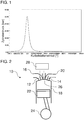
- the Figure 1 shows a cylinder pressure curve over a crankshaft angle of a crankshaft.
- a relatively high final compression pressure can be achieved during idling of an internal combustion engine in the compression stroke.
- the final compression pressure can be between, for example, 40 bar and 60 bar, in particular approximately 50 bar.
- the final compression pressure depends in particular on the compression ratio and the control times of the gas exchange valves.
- the compressed air extracted should be as clean as possible, so that extraction in the compression cycle is preferable to extraction, for example, in the combustion cycle.
- the respective cylinder is preferably in idle mode and / or not fired when the compressed air is withdrawn. However, it is also possible that the cylinder is fired.
- the extracted compressed air can be stored in a compressed air reservoir and / or (directly or indirectly) forwarded to pneumatic devices.
- compressed air in a range between 8 bar and 12 bar can be used to operate a large number of pneumatic devices, for example pneumatically operated brakes.
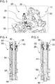
- the Figure 2 shows a schematic cylinder unit 10 of an internal combustion engine.
- the cylinder unit 10 is designed to remove compressed air.
- the internal combustion engine can for example be included in a motor vehicle, in particular a utility vehicle.
- the utility vehicle can be designed, for example, as an omnibus or a truck.
- the internal combustion engine can have a plurality of cylinder units 10 for drawing off compressed air, in particular when there is a high demand for compressed air. It is, however, also possible for the internal combustion engine to have a plurality of cylinder units, but to include only one cylinder unit according to the cylinder unit 10 for drawing off compressed air.
- the internal combustion engine can be, for example, a diesel internal combustion engine, a gasoline internal combustion engine, a gas internal combustion engine or a combination thereof.
- the cylinder unit 10 has several gas exchange valves 12, 14.
- the gas exchange valves 12, 14 comprise at least one inlet valve 12, e.g. B. exactly two inlet valves 12, and at least one outlet valve 14, z. B. exactly two outlet valves 14.
- the inlet valve 12 can establish a fluid connection between an inlet channel 16 and a combustion chamber 18.
- the exhaust valve 14 can establish fluid communication between the combustion chamber 18 and an exhaust passage 20.
- the cylinder unit 10 has a reciprocating piston 22 which is connected to a crankshaft 24.
- Compressed air can be taken from the cylinder unit 10 by means of an additional valve 26 of the cylinder unit 10.
- the additional valve 26, like, for example, the gas exchange valves 12, 14, can be arranged in a cylinder head (not shown separately) of the cylinder unit 10.
- the additional valve 26 is not operated separately or separately. Instead, the additional valve 26 is actuated by a valve drive 28 which also actuates at least one of the gas exchange valves 12, 14. As shown, the valve drive 28 can be arranged for actuating the at least one inlet valve 12 and the additional valve 26. For example, the valve drive 28 can be arranged in such a way that an operative connection between a camshaft (not shown in FIG Figure 2 ) and the at least one inlet valve 12 and the additional valve 26 can be produced. A further separate valve drive (not shown) can be provided for actuating the at least one outlet valve 14. It is possible for the valve train 28 to be a variable valve train.
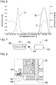
- FIGS Figure 3 shows an exemplary embodiment for the valve train 28.
- FIGS Figure 3 no inlet valve and outlet valves, but only the additional valve 26 shown.
- the valve drive 28 has a rocker arm 30.
- the rocker arm 30 is in operative connection between a camshaft 32 and the additional valve 26. It is also possible, as an alternative to the rocker arm 30, to switch another force transmission element between the camshaft 32 and the additional valve 26, for example a rocker arm or a tappet.
- the rocker arm 30 is also in operative connection with the at least one inlet valve 12 (see FIG Figure 2 ). If a cam of the camshaft 32 causes the rocker arm 30 to tilt, both the additional valve 26 and the at least one inlet valve 12 (see FIG Figure 2 ) are operated. The additional valve 26 is operated, so to speak, via the inlet valve rocker arm 30 co-controlled. As already mentioned, there is also the possibility that the additional valve is actuated via, for example, an inlet valve rocker arm, tappet or another force transmission device, which is expediently in operative connection between the camshaft on the one hand and an inlet valve and the additional valve on the other.
- the valve drive 28 also has a free travel device (a so-called lost motion element) 34.
- the idle travel device 34 is arranged and designed in such a way that actuation of the additional valve 26 by the rocker arm or the force transmission element 30 can be compensated for, that is to say prevented.
- the additional valve 26 can be selectively switched on by means of the idle travel device 34.
- the additional valve 26 and the at least one inlet valve 12 are actuated by the valve drive 28 according to a cam contour of a cam of the camshaft 32.
- the deactivated state of the idle travel device 34 for example the additional valve 26 is not actuated, but the at least one inlet valve 12 is actuated.
- the idle travel device 34 cannot prevent actuation of the intake valve 12.
- the free travel device 34 can be arranged, for example, between the rocker arm or the force transmission element 30 and the additional valve 26, as shown.
- the idle travel device 34 can be, for example, a hydraulic idle travel device 34.
- the idle travel device 34 can have a hydraulically actable pressure chamber, for example an oil chamber, and a displaceable and / or lockable piston. If, for example, a displacement of the piston is blocked due to the application of pressure to the pressure chamber, the additional valve 26 is actuated by the valve drive 28. If, for example, a displacement of the piston is enabled because the pressure chamber is not acted upon by hydraulic fluid, the additional valve 26 is not actuated (opened) by the valve drive 28. Instead, the piston can move in the free travel device 34.
- the additional valve 26 can be switched on for example by a corresponding switching of the idle travel device 34 when there is a need for compressed air.
- the additional valve 26 can preferably be switched on in non-fired operation and / or in idle operation of the cylinder unit 10. However, it is also possible for the additional valve 26, if desired, to switch on the cylinder unit 10 in a fired mode.
- the valve drive 28, in particular the additional valve 26, has a valve spring 36.
- the valve spring 36 can move the additional valve 26 in the direction of a closed position of the additional valve 26 preload. As a result, the additional valve 26 can be kept closed when not actuated.
- the Figures 4 and 5 show the additional valve 26 in a closed position ( Figure 4 ) and an open position ( Figure 5 ).
- the additional valve 26 can be designed as a poppet valve.
- the additional valve 26 has a locking device 38.
- the locking device 38 serves to keep the additional valve 26 open when the inlet valve 12 (see Figure 2 ) already closes.
- the locking device 38 also serves to provide a defined closing time for the additional valve 26.
- the locking device 38 can for example be arranged in a cylinder head.
- the locking device 38 has at least one locking body 40 and a recess and / or circumferential groove 42 into which the locking body 40 can engage.
- the locking body 40 can be designed as a ball, for example.
- the blocking body 40 can be acted upon elastically, for example spring-loaded, in particular in a direction towards the circumferential groove 42.
- the circumferential groove 42 can be provided in a valve stem 44 of the additional valve 26.
- the at least one locking body 40 In a closed position of the additional valve 26 (see Figure 4 ) the at least one locking body 40 is out of engagement with the circumferential groove 42. If the additional valve 26 is opened, the locking device 38 locks the additional valve 26 in the open position. In particular, the at least one locking body 40 engages in the circumferential groove 42. In detail, the at least one locking body 40 is moved in the direction of the circumferential groove 42 under the action of a spring, for example.
- the circumferential groove 42 and the at least one blocking body 40 are arranged with respect to one another in such a way that they can only be brought into engagement with one another in an open position of the additional valve 26.
- the locking device 38 produces a locking force which holds the additional valve 26 in the open position.
- a cylinder pressure at which the additional valve 26 closes again can be set via the locking force and the area ratios on the valve disk 46 of the additional valve 26.
- the additional valve 26 always closes at the same cylinder pressure, regardless of a speed, a boost pressure or a compression ratio of the internal combustion engine.
- the locking device 38 can be set such that the additional valve 26 closes at a predetermined cylinder pressure that is greater than 12 bar, for example in a range between approximately 18 bar and approximately 25 bar, for example at about 20 bar.
- the additional valve 26 can be arranged in such a way that it is in an open position by contact with the piston 22 (see FIG Figure 2 ) moving to a top dead center is movable toward a closed position. This can, for example, enable the additional valve 26 to be closed if the locking device 38 has a malfunction.
- the additional valve 26 can be made smaller than the gas exchange valves 12, 14.
- a diameter of the valve disk 46 of the additional valve 26 can be in a range between 10 mm and 14 mm.
- a diameter of a valve disk of the gas exchange valves 12, 14 can be between 30 mm and 40 mm.
- the Figure 6 shows an exemplary valve lift curve of the at least one intake valve 12 (solid curve B), an exemplary valve lift curve of the additional valve 26 (dotted curve C) and an exemplary cylinder pressure curve (knitting point curve D).
- the valve lift curves B and C and the cylinder pressure curve are shown over a crankshaft angle of the internal combustion engine.
- a valve lift of the additional valve 26 can be smaller than a valve lift of the inlet valve 12 (curve B).
- This can for example also be made possible by the fact that, as already mentioned, the air requirement for compressed air can be significantly smaller than the air requirement of the internal combustion engine for burning fuel. Due to the smaller valve lift, the additional valve 26 opens with a time delay to the inlet valve 12, although both are actuated by the same valve drive 28. This can have the advantage that no residual gas can flow into the additional valve 26 and thus only comparatively clean compressed air can be removed from the cylinder unit 10 via the additional valve 26.
- the additional valve 26 closes automatically at a cylinder pressure of approx. 18 bar. That is, in the example shown, the locking force caused by the locking device 38 is overcome at a cylinder pressure of 18 bar.
- the valve spring 36 moves the additional valve 26 back into the closed position.
- the Figure 7 shows a schematic structure of a device 48 for generating compressed air.
- the device 48 can be coupled to an internal combustion engine 50 or part thereof.
- the device 48 can have a cylinder unit 10 with the additional valve 26.
- several cylinder units of the internal combustion engine 50 can also be provided with an additional valve (not shown).
- the device 48 can also have a compressed air reservoir 52, for example a compressed air tank.
- a check valve 54 can be arranged in a fluid connection between the additional valve 26 and the compressed air reservoir 52.
- the check valve 54 can prevent a pressure applied to the pressure accumulator 52 from not constantly being applied to a valve stem seal of the additional valve 26.
- the check valve 54 enables the valve spring 36, which keeps the additional valve 26 closed when not actuated, to be designed to be significantly smaller.
- FIG. 11 shows an exemplary configuration for the check valve 54.
- the check valve 54 can be arranged in the cylinder head of the cylinder unit 10.
- the check valve 54 can have, for example, an elastically acted upon, in particular spring-acted, blocking body 56.
- the locking body 56 for. B. a ball lock body can close a compressed air channel 58 downstream of the additional valve 26.
- the check valve 54 can be opened when there is sufficient cylinder pressure and the additional valve 26 is open, in particular against the pressure downstream of the check valve 54 (for example pressure in the compressed air reservoir 52).
Landscapes
- Engineering & Computer Science (AREA)
- Mechanical Engineering (AREA)
- General Engineering & Computer Science (AREA)
- Chemical & Material Sciences (AREA)
- Combustion & Propulsion (AREA)
- Physics & Mathematics (AREA)
- Geometry (AREA)
- Valve Device For Special Equipments (AREA)
Claims (15)
- Dispositif de génération d'air comprimé pour un moteur à combustion interne (50) pour un véhicule automobile, en particulier un véhicule utilitaire, comprenant :plusieurs soupapes d'échange de gaz (12, 14) servant à l'amenée d'air de combustion jusqu'à une unité de cylindre (10) du moteur à combustion interne (50) et à l'évacuation de gaz d'échappement hors de l'unité de cylindre (10) ;une soupape auxiliaire (26) servant au prélèvement d'air comprimé de l'unité de cylindre (10) ; etune commande de soupapes (28) qui est en liaison fonctionnelle avec au moins une soupape d'admission (12) des plusieurs soupapes d'échange de gaz (12, 14) pour l'actionnement de l'au moins une soupape d'admission (12) et en liaison fonctionnelle avec la soupape auxiliaire (26) pour l'actionnement de la soupape auxiliaire (26), caractérisé en ce quela soupape auxiliaire (26) est actionnée par un culbuteur de soupape d'admission, un levier oscillant de soupape d'admission ou un poussoir de soupape d'admission.
- Dispositif selon la revendication 1, dans lequel : la soupape auxiliaire (26) et au moins la soupape d'admission (12) des plusieurs soupapes d'échange de gaz (12, 14) sont actionnées conjointement par le biais de la commande de soupapes (28).
- Dispositif selon la revendication 1 ou la revendication 2, dans lequel la commande de soupapes (28) comprend un dispositif de course à vide (34) qui :est réalisé pour activer, pour désactiver et/ou pour mettre en marche un actionnement de la soupape auxiliaire (26) par le biais de la commande de soupapes (28) ; et/ou est réalisé sous forme de dispositif de course à vide hydraulique ; et/ouest réalisé pour activer, pour désactiver et/ou pour mettre en marche un actionnement de la soupape auxiliaire (26) par le biais de la commande de soupapes (28) dans le fonctionnement de non allumage de l'unité de cylindre (10), dans le fonctionnement à vide de l'unité de cylindre (10) et/ou dans le fonctionnement d'allumage de l'unité de cylindre (10).
- Dispositif selon l'une des revendications précédentes, dans lequel :la soupape auxiliaire (26) peut être actionnée par la commande de soupapes (28) de telle sorte qu'elle ne s'ouvre en particulier que pendant le temps d'admission ; et/oula soupape auxiliaire (26) peut être actionnée par la commande de soupapes (28) de telle sorte qu'elle ne s'ouvre qu'après le début d'un temps d'admission et/ou après un point mort haut d'un déplacement de piston pendant le temps d'admission ; et/oula soupape auxiliaire (26) peut être actionnée par la commande de soupapes (28) de telle sorte qu'elle ne s'ouvre qu'après au moins la soupape d'admission (12) des plusieurs soupapes d'échange de gaz (12, 14) ; et/oula soupape auxiliaire (26) peut être actionnée par la commande de soupapes (28) de telle sorte qu'elle ne s'ouvre qu'après un chevauchement des plusieurs soupapes d'échange de gaz (12, 14).
- Dispositif selon l'une des revendications précédentes, dans lequel :la soupape auxiliaire (26) peut être fermée de manière pneumatique, en particulier par une pression de cylindre dans l'unité de cylindre (10) ; et/oula soupape auxiliaire (26) peut être actionnée de manière mécanique et pneumatique.
- Dispositif selon l'une des revendications précédentes, comprenant en outre :
un dispositif de blocage (38) par le biais duquel la soupape auxiliaire (26) peut être maintenue dans une position d'ouverture, en particulier même lorsque la commande de soupapes (28) ferme déjà ou a déjà fermé l'au moins une soupape d'admission (12). - Dispositif selon la revendication 6, dans lequel :la soupape auxiliaire (26) peut être maintenue par le biais du dispositif de blocage (38) dans la position d'ouverture jusqu'à ce qu'une force agissant sur la soupape auxiliaire (26) en raison d'une pression de cylindre dans l'unité de cylindre (10) surmonte une force de blocage du dispositif de blocage (38) ; et/oule dispositif de blocage (38) est réalisé de telle sorte qu'une force de blocage peut être surmontée pendant le temps de compression par la force agissant sur la soupape auxiliaire (26) en raison d'une pression de cylindre dans l'unité de cylindre (10) ; et/oule dispositif de blocage (38) est réalisé de telle sorte qu'une force de blocage est surmontée par la force agissant sur la soupape auxiliaire (26) en raison d'une pression de cylindre dans une plage supérieure à 12 bars, 15 bars, 18 bars, 20 bars, 22 bars et/ou 25 bars.
- Dispositif selon la revendication 6 ou la revendication 7, dans lequel :le dispositif de blocage (38) est réalisé de telle sorte qu'il ferme la soupape auxiliaire (26) toujours pour la même pression de cylindre ; et/oule dispositif de blocage (38) est réalisé de telle sorte qu'il ferme la soupape auxiliaire (26) indépendamment d'un régime du moteur à combustion interne (50), d'une pression de suralimentation du moteur à combustion interne (50) et/ou d'un rapport de compression de l'unité de cylindre (10).
- Dispositif selon l'une des revendications 6 à 8, le dispositif de blocage (38) comprenant :un corps de verrouillage (40) déplaçable, en particulier précontraint élastiquement ; etun évidement et/ou une rainure périphérique (42), en particulier sur une tige (44) de la soupape auxiliaire (26), évidement ou rainure dans lequel/laquelle le corps de verrouillage (40) vient en prise dans l'état d'ouverture de la soupape auxiliaire (26) pour maintenir ouverte la soupape auxiliaire (26) ; et/ouune force de blocage du dispositif de blocage comprend une force magnétique et/ou le dispositif de blocage comprend un aimant.
- Dispositif selon l'une des revendications précédentes, dans lequel :une section transversale d'écoulement pouvant être ouverte par la soupape auxiliaire (26) est inférieure à une section transversale d'écoulement pouvant être ouverte par l'au moins une soupape d'admission (12) ; et/oula soupape auxiliaire (26) est plus petite que les plusieurs soupapes d'échange de gaz (12, 14) ;
et/ouune tête (46) de la soupape auxiliaire (26) est plus petite qu'une tête des plusieurs soupapes d'échange de gaz (12, 14). - Dispositif selon l'une des revendications précédentes, dans lequel :la soupape auxiliaire (26) s'ouvre de manière retardée par rapport à l'au moins une soupape d'admission (12) ; et/ouune course de la soupape auxiliaire (26) est inférieure à une course de l'au moins une soupape d'admission (12) qui est actionnée par la commande de soupapes (28).
- Dispositif selon l'une des revendications précédentes, dans lequel :
une soupape anti-retour (54) qui est prévue en liaison fluidique en aval de la soupape auxiliaire (26). - Dispositif selon l'une des revendications précédentes, dans lequel :la soupape auxiliaire (26) est précontrainte en direction d'une position de fermeture, en particulier au moyen d'un ressort de soupape (36) ; et/oula soupape auxiliaire (26) et/ou la soupape anti-retour (54) est/sont disposée (s) dans une tête de cylindre de l'unité de cylindre (10) ; et/oula commande de soupapes (28) comprend le culbuteur (30), le levier oscillant ou le poussoir en liaison fonctionnelle entre un arbre à cames (32) et la soupape auxiliaire (26) ainsi que l'au moins une soupape d'admission (12) (12) .
- Dispositif selon l'une des revendications précédentes, dans lequel :
la soupape auxiliaire (26) est disposée de telle sorte qu'elle peut être déplacée à partir d'une position d'ouverture en direction de sa position de fermeture par contact avec un piston (22) de l'unité de cylindre (10), lequel piston se déplace jusqu'à un point mort haut d'un déplacement de piston. - Véhicule automobile, en particulier véhicule utilitaire, comprenant :
un moteur à combustion interne (50) doté d'un ou plusieurs dispositifs selon l'une des revendications précédentes ; et éventuellement :
un accumulateur d'air comprimé (52) qui est disposé en liaison fluidique en aval de la soupape auxiliaire (26) et/ou de la soupape anti-retour (54).
Applications Claiming Priority (1)
| Application Number | Priority Date | Filing Date | Title |
|---|---|---|---|
| DE102018108008.5A DE102018108008A1 (de) | 2018-04-05 | 2018-04-05 | Vorrichtung zur Drucklufterzeugung für eine Brennkraftmaschine mit einem Zusatzventil |
Publications (2)
| Publication Number | Publication Date |
|---|---|
| EP3550115A1 EP3550115A1 (fr) | 2019-10-09 |
| EP3550115B1 true EP3550115B1 (fr) | 2021-06-02 |
Family
ID=66092003
Family Applications (1)
| Application Number | Title | Priority Date | Filing Date |
|---|---|---|---|
| EP19166940.7A Active EP3550115B1 (fr) | 2018-04-05 | 2019-04-03 | Dispositif de génération d'air comprimé pour un moteur à combustion interne doté d'une soupape auxiliaire |
Country Status (2)
| Country | Link |
|---|---|
| EP (1) | EP3550115B1 (fr) |
| DE (1) | DE102018108008A1 (fr) |
Family Cites Families (10)
| Publication number | Priority date | Publication date | Assignee | Title |
|---|---|---|---|---|
| DE3041674A1 (de) * | 1980-11-05 | 1982-06-09 | Ernst Dipl.-Phys. 7730 Villingen-Schwenningen Jauch | Verfahren zur abspeicherung von angesogener luft bei schub- oder teillastbetrieb von verbrennungsmotoren von kraftfahrzeugen mit zylinderabschaltung |
| JPS59102958U (ja) * | 1982-12-27 | 1984-07-11 | 日野自動車株式会社 | 内燃機関補助空気制御機構 |
| JPS606026A (ja) * | 1984-04-17 | 1985-01-12 | Takahiro Ueno | 内燃機関の運転方法 |
| DE19849914C1 (de) | 1998-10-29 | 1999-11-04 | Daimler Chrysler Ag | Brennkraftmaschine mit einem separat betätigbaren Zusatzventil im Zylinderkopf |
| DE19902052C2 (de) * | 1999-01-20 | 2001-02-15 | Daimler Chrysler Ag | Brennkraftmaschine mit einem Verdichter zur Drucklufterzeugung |
| GB2402169B (en) * | 2003-05-28 | 2005-08-10 | Lotus Car | An engine with a plurality of operating modes including operation by compressed air |
| US20080087257A1 (en) * | 2006-04-24 | 2008-04-17 | Robinson Barnett J | Internal combustion engine with shared holding tank in cylinder head for elevated expansion ratio |
| DE102012206552A1 (de) * | 2012-04-20 | 2013-10-24 | Schaeffler Technologies AG & Co. KG | Brennkraftmaschine für ein Kraftfahrzeug |
| US9512789B2 (en) * | 2013-12-18 | 2016-12-06 | Hyundai Motor Company | Supercharging engine |
| DE102015203382A1 (de) * | 2015-02-25 | 2016-08-25 | Bayerische Motoren Werke Aktiengesellschaft | Verfahren zum Betrieb einer Brennkraftmaschine |
-
2018
- 2018-04-05 DE DE102018108008.5A patent/DE102018108008A1/de not_active Withdrawn
-
2019
- 2019-04-03 EP EP19166940.7A patent/EP3550115B1/fr active Active
Non-Patent Citations (1)
| Title |
|---|
| None * |
Also Published As
| Publication number | Publication date |
|---|---|
| EP3550115A1 (fr) | 2019-10-09 |
| DE102018108008A1 (de) | 2019-10-10 |
Similar Documents
| Publication | Publication Date | Title |
|---|---|---|
| DE102016003732A1 (de) | Variabler Ventilaktuator | |
| DE102017113783A1 (de) | Kraftübertragungsvorrichtung | |
| WO2009021666A1 (fr) | Dispositif d'actionnement de soupape de renouvellement des gaz | |
| EP4004350B1 (fr) | Dispositif de commande de soupape variable assurant la fonction de freinage | |
| DE102015016526A1 (de) | Verfahren zum Betreiben einer Hubkolben-Verbrennungskraftmaschine | |
| DE102015207622A1 (de) | Elektrohydraulischer Ventiltrieb für eine Brennkraftmaschine | |
| DE2802279C3 (de) | Abgas-Rückführanordnung für eine Viertakt-Brennkraftmaschine | |
| EP3536917B1 (fr) | Mécanisme de soupapes variable pourvu de système de cames coulissantes pour un moteur à combustion interne | |
| EP3084197B1 (fr) | Procédé de fonctionnement d'un moteur à combustion interne à pistons alternatifs | |
| EP3550115B1 (fr) | Dispositif de génération d'air comprimé pour un moteur à combustion interne doté d'une soupape auxiliaire | |
| EP2789853B1 (fr) | Dispositif de transport d'air comprimé pour des installations fonctionnant à l'air comprimé dans des véhicules automobiles | |
| DE102018123125A1 (de) | Vorrichtung zur Durchführung einer Mehrzyklenmotorbremsung | |
| DE102016013370A1 (de) | Brennkraftmaschinen vorrichtung zur Durchführung eines Direktstarts | |
| EP3519684B1 (fr) | Moteur à combustion interne à pistons alternatifs muni d'un dispositif permettant d'augmenter le couple du moteur | |
| DE102016213976A1 (de) | Elektrohydraulischer Ventiltrieb eines Verbrennungsmotors | |
| DE102016111526A1 (de) | Kraftstoffeinspritzdüse und Verfahren | |
| EP3564502B1 (fr) | Commande de soupape variable | |
| EP3620636B1 (fr) | Soupape de prise d'air comprimé | |
| WO2018068874A1 (fr) | Système de distribution | |
| DE102021118768A1 (de) | Ventilanordnung einer Brennkraftmaschine und eine Brennkraftmaschine | |
| DE10152503A1 (de) | Vorrichtung zur Steuerung von Gaswechselventilen | |
| DE10250771A1 (de) | Motorbremseinrichtung und Verfahren zu deren Steuerung | |
| DE102016015457A1 (de) | Verfahren zum Betreiben einer Hubkolben-Verbrennungskraftmaschine | |
| DE102021002758A1 (de) | Verbrennungskraftmaschine für ein Kraftfahrzeug | |
| DE102008027650A1 (de) | Ventilsteuerung für ein Gaswechselventil in einer Brennkraftmaschine |
Legal Events
| Date | Code | Title | Description |
|---|---|---|---|
| PUAI | Public reference made under article 153(3) epc to a published international application that has entered the european phase |
Free format text: ORIGINAL CODE: 0009012 |
|
| STAA | Information on the status of an ep patent application or granted ep patent |
Free format text: STATUS: THE APPLICATION HAS BEEN PUBLISHED |
|
| AK | Designated contracting states |
Kind code of ref document: A1 Designated state(s): AL AT BE BG CH CY CZ DE DK EE ES FI FR GB GR HR HU IE IS IT LI LT LU LV MC MK MT NL NO PL PT RO RS SE SI SK SM TR |
|
| AX | Request for extension of the european patent |
Extension state: BA ME |
|
| STAA | Information on the status of an ep patent application or granted ep patent |
Free format text: STATUS: REQUEST FOR EXAMINATION WAS MADE |
|
| 17P | Request for examination filed |
Effective date: 20200407 |
|
| RBV | Designated contracting states (corrected) |
Designated state(s): AL AT BE BG CH CY CZ DE DK EE ES FI FR GB GR HR HU IE IS IT LI LT LU LV MC MK MT NL NO PL PT RO RS SE SI SK SM TR |
|
| REG | Reference to a national code |
Ref country code: DE Ref legal event code: R079 Ref document number: 502019001523 Country of ref document: DE Free format text: PREVIOUS MAIN CLASS: F01L0001260000 Ipc: F02B0033220000 |
|
| RIC1 | Information provided on ipc code assigned before grant |
Ipc: F02D 13/06 20060101ALI20201102BHEP Ipc: F02B 33/30 20060101ALI20201102BHEP Ipc: F01L 3/24 20060101ALI20201102BHEP Ipc: F01L 23/00 20060101ALI20201102BHEP Ipc: F01L 1/18 20060101ALI20201102BHEP Ipc: F01L 1/46 20060101ALI20201102BHEP Ipc: F02D 17/02 20060101ALI20201102BHEP Ipc: F01L 3/20 20060101ALI20201102BHEP Ipc: F01L 13/00 20060101ALI20201102BHEP Ipc: F02D 13/02 20060101ALI20201102BHEP Ipc: F01L 1/14 20060101ALI20201102BHEP Ipc: F02B 33/22 20060101AFI20201102BHEP Ipc: F01L 1/26 20060101ALI20201102BHEP |
|
| GRAJ | Information related to disapproval of communication of intention to grant by the applicant or resumption of examination proceedings by the epo deleted |
Free format text: ORIGINAL CODE: EPIDOSDIGR1 |
|
| GRAP | Despatch of communication of intention to grant a patent |
Free format text: ORIGINAL CODE: EPIDOSNIGR1 |
|
| STAA | Information on the status of an ep patent application or granted ep patent |
Free format text: STATUS: GRANT OF PATENT IS INTENDED |
|
| GRAP | Despatch of communication of intention to grant a patent |
Free format text: ORIGINAL CODE: EPIDOSNIGR1 |
|
| GRAJ | Information related to disapproval of communication of intention to grant by the applicant or resumption of examination proceedings by the epo deleted |
Free format text: ORIGINAL CODE: EPIDOSDIGR1 |
|
| GRAP | Despatch of communication of intention to grant a patent |
Free format text: ORIGINAL CODE: EPIDOSNIGR1 |
|
| STAA | Information on the status of an ep patent application or granted ep patent |
Free format text: STATUS: REQUEST FOR EXAMINATION WAS MADE |
|
| GRAJ | Information related to disapproval of communication of intention to grant by the applicant or resumption of examination proceedings by the epo deleted |
Free format text: ORIGINAL CODE: EPIDOSDIGR1 |
|
| GRAJ | Information related to disapproval of communication of intention to grant by the applicant or resumption of examination proceedings by the epo deleted |
Free format text: ORIGINAL CODE: EPIDOSDIGR1 |
|
| GRAP | Despatch of communication of intention to grant a patent |
Free format text: ORIGINAL CODE: EPIDOSNIGR1 |
|
| INTG | Intention to grant announced |
Effective date: 20201216 |
|
| INTG | Intention to grant announced |
Effective date: 20201216 |
|
| INTC | Intention to grant announced (deleted) | ||
| GRAP | Despatch of communication of intention to grant a patent |
Free format text: ORIGINAL CODE: EPIDOSNIGR1 |
|
| STAA | Information on the status of an ep patent application or granted ep patent |
Free format text: STATUS: GRANT OF PATENT IS INTENDED |
|
| INTG | Intention to grant announced |
Effective date: 20210223 |
|
| GRAS | Grant fee paid |
Free format text: ORIGINAL CODE: EPIDOSNIGR3 |
|
| GRAA | (expected) grant |
Free format text: ORIGINAL CODE: 0009210 |
|
| STAA | Information on the status of an ep patent application or granted ep patent |
Free format text: STATUS: THE PATENT HAS BEEN GRANTED |
|
| REG | Reference to a national code |
Ref country code: CH Ref legal event code: EP |
|
| AK | Designated contracting states |
Kind code of ref document: B1 Designated state(s): AL AT BE BG CH CY CZ DE DK EE ES FI FR GB GR HR HU IE IS IT LI LT LU LV MC MK MT NL NO PL PT RO RS SE SI SK SM TR |
|
| REG | Reference to a national code |
Ref country code: GB Ref legal event code: FG4D Free format text: NOT ENGLISH |
|
| REG | Reference to a national code |
Ref country code: AT Ref legal event code: REF Ref document number: 1398640 Country of ref document: AT Kind code of ref document: T Effective date: 20210615 |
|
| REG | Reference to a national code |
Ref country code: IE Ref legal event code: FG4D Free format text: LANGUAGE OF EP DOCUMENT: GERMAN |
|
| REG | Reference to a national code |
Ref country code: DE Ref legal event code: R096 Ref document number: 502019001523 Country of ref document: DE |
|
| REG | Reference to a national code |
Ref country code: NL Ref legal event code: FP |
|
| REG | Reference to a national code |
Ref country code: SE Ref legal event code: TRGR |
|
| REG | Reference to a national code |
Ref country code: LT Ref legal event code: MG9D |
|
| PG25 | Lapsed in a contracting state [announced via postgrant information from national office to epo] |
Ref country code: FI Free format text: LAPSE BECAUSE OF FAILURE TO SUBMIT A TRANSLATION OF THE DESCRIPTION OR TO PAY THE FEE WITHIN THE PRESCRIBED TIME-LIMIT Effective date: 20210602 Ref country code: LT Free format text: LAPSE BECAUSE OF FAILURE TO SUBMIT A TRANSLATION OF THE DESCRIPTION OR TO PAY THE FEE WITHIN THE PRESCRIBED TIME-LIMIT Effective date: 20210602 Ref country code: HR Free format text: LAPSE BECAUSE OF FAILURE TO SUBMIT A TRANSLATION OF THE DESCRIPTION OR TO PAY THE FEE WITHIN THE PRESCRIBED TIME-LIMIT Effective date: 20210602 Ref country code: BG Free format text: LAPSE BECAUSE OF FAILURE TO SUBMIT A TRANSLATION OF THE DESCRIPTION OR TO PAY THE FEE WITHIN THE PRESCRIBED TIME-LIMIT Effective date: 20210902 |
|
| PG25 | Lapsed in a contracting state [announced via postgrant information from national office to epo] |
Ref country code: GR Free format text: LAPSE BECAUSE OF FAILURE TO SUBMIT A TRANSLATION OF THE DESCRIPTION OR TO PAY THE FEE WITHIN THE PRESCRIBED TIME-LIMIT Effective date: 20210903 Ref country code: LV Free format text: LAPSE BECAUSE OF FAILURE TO SUBMIT A TRANSLATION OF THE DESCRIPTION OR TO PAY THE FEE WITHIN THE PRESCRIBED TIME-LIMIT Effective date: 20210602 Ref country code: PL Free format text: LAPSE BECAUSE OF FAILURE TO SUBMIT A TRANSLATION OF THE DESCRIPTION OR TO PAY THE FEE WITHIN THE PRESCRIBED TIME-LIMIT Effective date: 20210602 Ref country code: NO Free format text: LAPSE BECAUSE OF FAILURE TO SUBMIT A TRANSLATION OF THE DESCRIPTION OR TO PAY THE FEE WITHIN THE PRESCRIBED TIME-LIMIT Effective date: 20210902 Ref country code: RS Free format text: LAPSE BECAUSE OF FAILURE TO SUBMIT A TRANSLATION OF THE DESCRIPTION OR TO PAY THE FEE WITHIN THE PRESCRIBED TIME-LIMIT Effective date: 20210602 |
|
| PG25 | Lapsed in a contracting state [announced via postgrant information from national office to epo] |
Ref country code: CZ Free format text: LAPSE BECAUSE OF FAILURE TO SUBMIT A TRANSLATION OF THE DESCRIPTION OR TO PAY THE FEE WITHIN THE PRESCRIBED TIME-LIMIT Effective date: 20210602 Ref country code: SM Free format text: LAPSE BECAUSE OF FAILURE TO SUBMIT A TRANSLATION OF THE DESCRIPTION OR TO PAY THE FEE WITHIN THE PRESCRIBED TIME-LIMIT Effective date: 20210602 Ref country code: RO Free format text: LAPSE BECAUSE OF FAILURE TO SUBMIT A TRANSLATION OF THE DESCRIPTION OR TO PAY THE FEE WITHIN THE PRESCRIBED TIME-LIMIT Effective date: 20210602 Ref country code: PT Free format text: LAPSE BECAUSE OF FAILURE TO SUBMIT A TRANSLATION OF THE DESCRIPTION OR TO PAY THE FEE WITHIN THE PRESCRIBED TIME-LIMIT Effective date: 20211004 Ref country code: SK Free format text: LAPSE BECAUSE OF FAILURE TO SUBMIT A TRANSLATION OF THE DESCRIPTION OR TO PAY THE FEE WITHIN THE PRESCRIBED TIME-LIMIT Effective date: 20210602 Ref country code: EE Free format text: LAPSE BECAUSE OF FAILURE TO SUBMIT A TRANSLATION OF THE DESCRIPTION OR TO PAY THE FEE WITHIN THE PRESCRIBED TIME-LIMIT Effective date: 20210602 Ref country code: ES Free format text: LAPSE BECAUSE OF FAILURE TO SUBMIT A TRANSLATION OF THE DESCRIPTION OR TO PAY THE FEE WITHIN THE PRESCRIBED TIME-LIMIT Effective date: 20210602 |
|
| REG | Reference to a national code |
Ref country code: DE Ref legal event code: R097 Ref document number: 502019001523 Country of ref document: DE |
|
| PLBE | No opposition filed within time limit |
Free format text: ORIGINAL CODE: 0009261 |
|
| STAA | Information on the status of an ep patent application or granted ep patent |
Free format text: STATUS: NO OPPOSITION FILED WITHIN TIME LIMIT |
|
| PG25 | Lapsed in a contracting state [announced via postgrant information from national office to epo] |
Ref country code: DK Free format text: LAPSE BECAUSE OF FAILURE TO SUBMIT A TRANSLATION OF THE DESCRIPTION OR TO PAY THE FEE WITHIN THE PRESCRIBED TIME-LIMIT Effective date: 20210602 |
|
| 26N | No opposition filed |
Effective date: 20220303 |
|
| PG25 | Lapsed in a contracting state [announced via postgrant information from national office to epo] |
Ref country code: AL Free format text: LAPSE BECAUSE OF FAILURE TO SUBMIT A TRANSLATION OF THE DESCRIPTION OR TO PAY THE FEE WITHIN THE PRESCRIBED TIME-LIMIT Effective date: 20210602 |
|
| REG | Reference to a national code |
Ref country code: CH Ref legal event code: PL |
|
| REG | Reference to a national code |
Ref country code: BE Ref legal event code: MM Effective date: 20220430 |
|
| PG25 | Lapsed in a contracting state [announced via postgrant information from national office to epo] |
Ref country code: MC Free format text: LAPSE BECAUSE OF FAILURE TO SUBMIT A TRANSLATION OF THE DESCRIPTION OR TO PAY THE FEE WITHIN THE PRESCRIBED TIME-LIMIT Effective date: 20210602 Ref country code: LU Free format text: LAPSE BECAUSE OF NON-PAYMENT OF DUE FEES Effective date: 20220403 Ref country code: LI Free format text: LAPSE BECAUSE OF NON-PAYMENT OF DUE FEES Effective date: 20220430 Ref country code: CH Free format text: LAPSE BECAUSE OF NON-PAYMENT OF DUE FEES Effective date: 20220430 |
|
| PG25 | Lapsed in a contracting state [announced via postgrant information from national office to epo] |
Ref country code: BE Free format text: LAPSE BECAUSE OF NON-PAYMENT OF DUE FEES Effective date: 20220430 |
|
| PG25 | Lapsed in a contracting state [announced via postgrant information from national office to epo] |
Ref country code: IE Free format text: LAPSE BECAUSE OF NON-PAYMENT OF DUE FEES Effective date: 20220403 |
|
| PG25 | Lapsed in a contracting state [announced via postgrant information from national office to epo] |
Ref country code: HU Free format text: LAPSE BECAUSE OF FAILURE TO SUBMIT A TRANSLATION OF THE DESCRIPTION OR TO PAY THE FEE WITHIN THE PRESCRIBED TIME-LIMIT; INVALID AB INITIO Effective date: 20190403 |
|
| PG25 | Lapsed in a contracting state [announced via postgrant information from national office to epo] |
Ref country code: MK Free format text: LAPSE BECAUSE OF FAILURE TO SUBMIT A TRANSLATION OF THE DESCRIPTION OR TO PAY THE FEE WITHIN THE PRESCRIBED TIME-LIMIT Effective date: 20210602 Ref country code: CY Free format text: LAPSE BECAUSE OF FAILURE TO SUBMIT A TRANSLATION OF THE DESCRIPTION OR TO PAY THE FEE WITHIN THE PRESCRIBED TIME-LIMIT Effective date: 20210602 |
|
| PG25 | Lapsed in a contracting state [announced via postgrant information from national office to epo] |
Ref country code: MT Free format text: LAPSE BECAUSE OF FAILURE TO SUBMIT A TRANSLATION OF THE DESCRIPTION OR TO PAY THE FEE WITHIN THE PRESCRIBED TIME-LIMIT Effective date: 20210602 |
|
| PGFP | Annual fee paid to national office [announced via postgrant information from national office to epo] |
Ref country code: NL Payment date: 20250424 Year of fee payment: 7 |
|
| REG | Reference to a national code |
Ref country code: AT Ref legal event code: MM01 Ref document number: 1398640 Country of ref document: AT Kind code of ref document: T Effective date: 20240403 |
|
| PGFP | Annual fee paid to national office [announced via postgrant information from national office to epo] |
Ref country code: DE Payment date: 20250428 Year of fee payment: 7 |
|
| PGFP | Annual fee paid to national office [announced via postgrant information from national office to epo] |
Ref country code: GB Payment date: 20250422 Year of fee payment: 7 |
|
| PGFP | Annual fee paid to national office [announced via postgrant information from national office to epo] |
Ref country code: IT Payment date: 20250422 Year of fee payment: 7 |
|
| PGFP | Annual fee paid to national office [announced via postgrant information from national office to epo] |
Ref country code: FR Payment date: 20250424 Year of fee payment: 7 |
|
| PG25 | Lapsed in a contracting state [announced via postgrant information from national office to epo] |
Ref country code: AT Free format text: LAPSE BECAUSE OF NON-PAYMENT OF DUE FEES Effective date: 20240403 |
|
| PGFP | Annual fee paid to national office [announced via postgrant information from national office to epo] |
Ref country code: SE Payment date: 20250424 Year of fee payment: 7 |
|
| PG25 | Lapsed in a contracting state [announced via postgrant information from national office to epo] |
Ref country code: TR Free format text: LAPSE BECAUSE OF FAILURE TO SUBMIT A TRANSLATION OF THE DESCRIPTION OR TO PAY THE FEE WITHIN THE PRESCRIBED TIME-LIMIT Effective date: 20210602 |
|
| PGFP | Annual fee paid to national office [announced via postgrant information from national office to epo] |
Ref country code: AT Payment date: 20260410 Year of fee payment: 5 |