EP3550162A1 - Procédé de fabrication d'un câble d'entraînement - Google Patents
Procédé de fabrication d'un câble d'entraînement Download PDFInfo
- Publication number
- EP3550162A1 EP3550162A1 EP19172315.4A EP19172315A EP3550162A1 EP 3550162 A1 EP3550162 A1 EP 3550162A1 EP 19172315 A EP19172315 A EP 19172315A EP 3550162 A1 EP3550162 A1 EP 3550162A1
- Authority
- EP
- European Patent Office
- Prior art keywords
- cable
- pitch
- pitch cable
- sleeve
- driver
- Prior art date
- Legal status (The legal status is an assumption and is not a legal conclusion. Google has not performed a legal analysis and makes no representation as to the accuracy of the status listed.)
- Granted
Links
Images


Classifications
-
- F—MECHANICAL ENGINEERING; LIGHTING; HEATING; WEAPONS; BLASTING
- F16—ENGINEERING ELEMENTS AND UNITS; GENERAL MEASURES FOR PRODUCING AND MAINTAINING EFFECTIVE FUNCTIONING OF MACHINES OR INSTALLATIONS; THERMAL INSULATION IN GENERAL
- F16C—SHAFTS; FLEXIBLE SHAFTS; ELEMENTS OR CRANKSHAFT MECHANISMS; ROTARY BODIES OTHER THAN GEARING ELEMENTS; BEARINGS
- F16C1/00—Flexible shafts; Mechanical means for transmitting movement in a flexible sheathing
- F16C1/10—Means for transmitting linear movement in a flexible sheathing, e.g. "Bowden-mechanisms"
- F16C1/12—Arrangements for transmitting movement to or from the flexible member
- F16C1/14—Construction of the end-piece of the flexible member; Attachment thereof to the flexible member
- F16C1/145—Attachment of the end-piece to the flexible member
-
- B—PERFORMING OPERATIONS; TRANSPORTING
- B60—VEHICLES IN GENERAL
- B60J—WINDOWS, WINDSCREENS, NON-FIXED ROOFS, DOORS, OR SIMILAR DEVICES FOR VEHICLES; REMOVABLE EXTERNAL PROTECTIVE COVERINGS SPECIALLY ADAPTED FOR VEHICLES
- B60J7/00—Non-fixed roofs; Roofs with movable panels, e.g. rotary sunroofs
- B60J7/02—Non-fixed roofs; Roofs with movable panels, e.g. rotary sunroofs of sliding type, e.g. comprising guide shoes
- B60J7/04—Non-fixed roofs; Roofs with movable panels, e.g. rotary sunroofs of sliding type, e.g. comprising guide shoes with rigid plate-like element or elements, e.g. open roofs with harmonica-type folding rigid panels
- B60J7/057—Driving or actuating arrangements e.g. manually operated levers or knobs
- B60J7/0573—Driving or actuating arrangements e.g. manually operated levers or knobs power driven arrangements, e.g. electrical
-
- F—MECHANICAL ENGINEERING; LIGHTING; HEATING; WEAPONS; BLASTING
- F16—ENGINEERING ELEMENTS AND UNITS; GENERAL MEASURES FOR PRODUCING AND MAINTAINING EFFECTIVE FUNCTIONING OF MACHINES OR INSTALLATIONS; THERMAL INSULATION IN GENERAL
- F16C—SHAFTS; FLEXIBLE SHAFTS; ELEMENTS OR CRANKSHAFT MECHANISMS; ROTARY BODIES OTHER THAN GEARING ELEMENTS; BEARINGS
- F16C1/00—Flexible shafts; Mechanical means for transmitting movement in a flexible sheathing
- F16C1/10—Means for transmitting linear movement in a flexible sheathing, e.g. "Bowden-mechanisms"
- F16C1/20—Construction of flexible members moved to and fro in the sheathing
-
- F—MECHANICAL ENGINEERING; LIGHTING; HEATING; WEAPONS; BLASTING
- F16—ENGINEERING ELEMENTS AND UNITS; GENERAL MEASURES FOR PRODUCING AND MAINTAINING EFFECTIVE FUNCTIONING OF MACHINES OR INSTALLATIONS; THERMAL INSULATION IN GENERAL
- F16C—SHAFTS; FLEXIBLE SHAFTS; ELEMENTS OR CRANKSHAFT MECHANISMS; ROTARY BODIES OTHER THAN GEARING ELEMENTS; BEARINGS
- F16C2226/00—Joining parts; Fastening; Assembling or mounting parts
- F16C2226/50—Positive connections
- F16C2226/60—Positive connections with threaded parts, e.g. bolt and nut connections
Definitions
- the invention relates to a method for producing a pitch cable, in particular for the operation of sliding roofs or luggage compartment covers of vehicles, to which at a portion of the pitch cable, in particular its one end a driver for power transmission, for example, on sunroofs or cargo space covers of vehicles, are attached.
- Slope cable of the type mentioned which are also known as drive cable or flex shaft, are preferably used in lifting and / or sliding roofs, shading blinds and luggage compartment covers of motor vehicles.
- the pitch cables are axially adjustable, for example, by means of a motor-driven worm and are coupled via a driver to a component to be adjusted, for example to the sunroof, i.
- the drivers also provide the power transmission here.
- the pitch cables are usually made of multi-strand metal cables with applied pitch helices as endless and then have to be cut to the required length.
- the sunroof is coupled on both sides, each with a driver of a pitch cable.
- There are also constructive embodiments are known in which two pitch cables run around the roof opening of the sunroof to a common drive, where they engage with a gear which engages the pitches of the pitch cable and actuates them like a rack.
- the DE 7306 032 U discloses a power window for motor vehicles, wherein by means of a crank-operated gear, a pitch cable is displaced in a longitudinally slotted guide tube at least partially parallel to the direction of movement of the window.
- a driver On the pitch cable a driver is attached.
- the driver can be made of plastic and as a separate, provided with an internal thread part, which is subsequently screwed onto one end of the pitch cable, or be formed as directly sprayed on the pitch cable part.
- drivers on pitch cables of the aforementioned type are also known, which are designed as cast metal casting.
- a pitch cable is described at the one end Driver is attached, which is designed for coupling to a movable in the axial direction of the pitch cable sliding element.
- the driver is cast as around the end of the pitch cable Formed metal body and has a coupling formed for lateral recess, which in the axial direction beyond the end of the Gradient cable is arranged.
- an axially parallel pin is also cast in the remaining in addition to the recess cross-section of the driver.
- pitch cable which consist of plastic and are molded by injection molding around the end of the pitch cable.
- a die-cast carrier which is integrally connected to parts of a carriage body.
- the die-cast support may be attached to a steel cantilever formed as a sheet metal bent part, which forms at least one web and a leg of the carriage body.
- the leg can also be part of the bent sheet metal part.
- the leg is formed there by a plastic part connected to a steel arm, which allows a simple and effective anchoring to the pitch cable by melting by means of ultrasound.
- the plastic part in its region encompassing the pitch cable can preferably be softened by applying ultrasound in such a way that material of the plastic part penetrates into intermediate spaces of the drive cable, which consists, for example, of twisted individual wires.
- the DE 30 15 965 A1 describes an assembly guide for the movement of a sunroof.
- the assembly guide consists of a control cable with a core made of steel wire and a guide body made of plastic, to which a sleeve is formed, in which a soul is attached.
- the soul is with the sleeve train and rotatably welded.
- the FR 2 482 905 A1 discloses a window crank device for the controlled adjustment of movable vehicle windows, with one at an edge portion of a window pane attachable plate and with at least one slidably connected to the plate, arranged parallel to the displacement direction of the window glass guide and connected to the plate via fasteners flexible, the plate along the guide displacing actuator.
- the actuator is formed by a flexible screw spindle, which consists of a flexible metal core and an outer shell.
- the flexible screw spindle extends along a guide tube and engages in a thread formed in a cylindrical sleeve, so that a firm and rigid connection with the plate is made.
- the US 3 444 701 A discloses a mounting bracket with a Bowden cable.
- the Bowden train again consists of an inner wire, which is led through an outer part.
- a shell is formed around the outer part so that there is a firm connection between the outer part and the shell.
- the US 4,570,893 describes a mechanism to adjust the position of an outside mirror of a motor vehicle.
- nut elements are provided in the mirror device within a wall in which run spring parts.
- the nut members and the spring members have corresponding helical shapes. During a movement, ie a rotation of the spring parts, the spring parts can move through the nut elements.
- a pitch cable emerges that has a core consisting of twisted wires.
- the core is wrapped tightly with a helix, which should absorb high forces in the axial direction of the core.
- the core has an end portion which passes through a bore in a bore portion of the driver.
- a stopper body is attached at the end of the core.
- the deformable metal stopper is fixed to the notch on the core at one stroke. It lies with a surface against the end of the bore part, while the other end of the bore part lies against the end of the helix.
- the DE 26 59 268 A1 discloses an end termination of a tensile and compressive force transmitting cable in the form of a sleeve which is screwed onto the cable in the axial direction. Through the union nut in the DE 26 59 268 A1 should be provided a technically simple backup of the final.
- the sleeve is not Part which, during its movement, also sets another part in motion, ie, serves to transmit power.
- the sleeve in the DE 26 59 268 A1 is intended for attachment of the cable end to a main electrical switch of a vehicle.
- the DE 29 12 666 A1 discloses a connection device between a drive cable and a Gleitfuß, which sits slidably in a first guide groove of a fixed part and having a lug, wherein the drive cable is toothed on its surface and displaceable by means of a drive device in the axial direction.
- the drive cable is formed in the approach when forming the Gleitfußes made of plastic, so that the drive cable and the approach are integrally connected.
- the DE 24 18 110 A discloses a Bowden cable consisting of an elongated flexible core with a core and a helically wound wire around the core with spaced turns, with a polymeric material fitting in an array around the core for enclosing the helical wire and core in FIG the areas between successive turns of the helical wire is provided.
- the connector is shaped so that it is disposed around the soul and umbettet the helical wires and the core in the areas between successive turns of the helical wire.
- the DE 10 2010 015 130 A1 discloses a coiled cable drive of a mobile device of a motor vehicle having at least one multi-turn coiled cable connected to a drive means for moving the device via a mechanical operative connection, wherein a drive transducer means converts rotary drive motion of the drive means into translational movement of the coiled cable and wherein the drive transducer means has at least one rotational drive receiving the spindle nut, which surrounds the spiral cable in the region of at least one turn.
- Upon rotation of the spiral nut relative to the spiral cable is caused by a slope of the turns of the spiral cable translational movement of the spiral cable relative to the spindle nut, which is already transmitted by small forces of the spindle nut on the spiral cable.
- a disadvantage of the pitch cables known from the prior art, in particular, is that for each pitch cable to be produced, the driver is cast by injection molding around the end portion of the pitch cable, which represents a not inconsiderable expense against the background of a necessary cost-effective mass production of pitch cables.
- the driver on the pitch cable can be fixed in the form of a bond and / or fusion and / or welding.
- the driver ensures that the driver can initially be formed or produced separately from the pitch cable, as due to the pitch helix of the pitch cable and the corresponding internal thread of the driver screwing the driver on the end of the pitch cable is possible. Only after this process is the actual fixation of the driver.
- the driver is preferably used as a free-falling plastic injection molded part, i. produced by machine as part of a mass production. This fixation is preferably carried out in the form of an ultrasonic welding, gluing, or melting.
- the pitch cable is provided at its second end with a closure sleeve having a bore whose geometry or internal geometry is different from the bore of the driver.
- the end of the pitch cable is processed before connecting to the end sleeve so that the end is at least partially adapted to the corresponding receptacle of the end sleeve.
- the fixation of the driver or the connecting sleeve is preferably carried out by gluing and / or fusing and / or welding.
- a further advantageous embodiment of the invention provides that the driver is fixed by heating, preferably by inductive heating.
- the driver which is expediently made of plastic, is pressed after the heating.
- the driver can first be cold screwed or rotated on a portion of the pitch cable to then heat the driver inductively. After this step, the driver is pressed by means of a pressing tool or a pressing device in tenths of a millimeter range against the pitch cable.
- the joining of the driver and / or the terminating sleeve on the pitch cable can thereby be rotary (screwing) or linear.
- the driver is designed as a plastic injection molded part.
- the schigwinde is formed as a cast. This advantageously ensures that the Kunststoffmit freelance can be made unattended and cost.
- a practicable variant of the invention provides that the pitch cable is provided outside of the driver between the turns of the pitch helix with flocking threads.
- the flocking is advantageously carried out by wrapping or melting of Flockgarnfäden, which consist for example of polyamide and serve to combat noise when moving the pitch cable.
- Such flock yarns for pitch cable are for example from the WO 2009/030376 A1 .
- This fixation is preferably carried out in the form of an ultrasonic welding, gluing, or melting.
- the driver is formed as a metal-plastic component with a molded sheet metal insert, whereby the stability of the driver is further increased.
- the pitch cable is provided with a terminating sleeve at its second end.
- a termination sleeve is in the DE 10 2008 005 983 A1 described.
- the pre-cut pitch cables tend to splice due to the loose strands of the cable.
- Another problem of the known Slope cable is that they tend to rattle in the assembled state at the ends.
- the proposed cover sleeve avoids these disadvantages.
- the cover sleeve has a bore, the wall of which in turn has a shape corresponding to the lead helix.
- the attachment or fixation of the cover sleeve on the slope cable end is done automatically, for example by ultrasonic welding, gluing, or melting.
- the region of the pitch cable, at which the fixation of the driver or the terminating sleeve is to take place is inductively heated prior to the mounting of the driver and / or terminating sleeve.
- the heating of the pitch cable can also be done after the assembly of the driver.
- a depth of engagement of 30 mm is provided, only the range of e.g. 20 mm to 30 mm, starting from one end of the pitch cable, inductively heated, d. that is, in this preferred variant, the end portion of the pitch cable, e.g. 20 mm at the end of the pitch cable is not heated, but only e.g. Heated 10 mm, which are spaced in the range of 20 mm to 30 mm from one end of the pitch cable. A deformation of the driver is thus advantageously avoided.
- the melting or the fusion of pitch cable and driver and / or terminating sleeve serves to fix the driver and / or the terminating sleeve on the pitch cable.
- connection strength or the peel strength between pitch cable and driver is achieved by the screw connection between pitch cable and driver.
- a practicable variant of the invention provides that the fixation of the terminating sleeve takes place on the pitch cable.
- the end of the pitch cable is processed prior to connection to the end sleeve so that the end, the end portion and the tip of the pitch cable is adapted for connection to the end sleeve.
- the shape of the end of the pitch cable can be at least partially adapted to the corresponding receptacle in the end sleeve.
- the end sleeve preferably has a bore with a coherently formed shape.
- a preferably made of plastic end sleeve is mounted so that a fixation can be done by melting the end sleeve on the cable end.
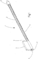
- Fig. 1 shows a pitch cable, which is provided with the reference numeral 1.
- the pitch cable 1 has a core 2, which is formed in the embodiment chosen here from multi-layered in opposite directions superimposed wires, which consist of metal or plastic.
- the pitch cable 1 is how FIG. 1 further illustrated, provided with a arranged at one end driver 4.
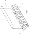
- the driver 4 is fixed on the pitch cable 1 and has a bore 5, in which a corresponding to the pitch helix 3 in FIG. 2 shown inner portion 7 is shown in the form of an internal thread is formed.
- the inner portion 7 simultaneously represents the wall of the bore 5.
- FIG. 1 shows further that the pitch cable 1 is provided at its second end with a cover sleeve 6, which forms the conclusion of the pitch cable 1 and to which the pitch cable 1 is attached.
- the cover sleeve 6 has been automatically applied to the pitch cable 1.
- the in FIG. 2 shown driver 4 is provided with a surface element 8, which, projecting from the driver 4, for coupling with a movable sliding element, such as a sunroof of a motor vehicle, is provided.
- the driver 4 has, as FIG. 2 further illustrates the inner portion 7 in the form of an internal thread, which is formed as a cast.
- the driver 4 as a plastic injection molded part is separated from the in FIG. 1 formed pitch cable 1, ie the in FIG. 1 shown driver 4 is initially not integral part of the pitch cable 1 and separated from the pitch cable 1.
- connection and union of pitch cable 1 and driver 4 is carried out in the context of the method according to the invention, whose course the FIGS. 3a to 3c clarify.
- the method begins with the production of a gradient cable 3 provided with a pitch cable 1 and with the preparation of a provided with a bore 5 driver 4, wherein within the bore 5 a corresponding to the pitch helix 3 inner portion 7 is formed in the form of an internal thread.
- driver 4 is initially not an integral part of the pitch cable 1 and separated from this.
- the in FIG. 3a shown driver 4 is made as a free-falling plastic injection molded part.
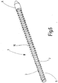
- FIG. 4 shows that in the production of the pitch cable 1, starting from an endless pitch cable, this first, ie before application and fixation of the in FIGS. 3a to 3c shown driver 4, is cut to length. After the pitch cable has been cut to length, how can FIG. 5 illustrates the termination sleeve are automatically applied to one end of the pitch cable 1.
- the pitch cable 1 is wrapped outside of the driver 5 between the turns of the pitch helix 3 of Flockgarnfäden 10, which serves to avoid noise during movement of the pitch cable 1.
- the flock threads 10 are removed.
- the present invention is not limited in its execution to the above-mentioned preferred embodiment. Rather, a number of variants is conceivable, which make use of the solution shown in other types.
Landscapes
- Engineering & Computer Science (AREA)
- General Engineering & Computer Science (AREA)
- Mechanical Engineering (AREA)
- Health & Medical Sciences (AREA)
- Oral & Maxillofacial Surgery (AREA)
- Flexible Shafts (AREA)
- Ropes Or Cables (AREA)
- Injection Moulding Of Plastics Or The Like (AREA)
Applications Claiming Priority (3)
| Application Number | Priority Date | Filing Date | Title |
|---|---|---|---|
| DE102016104918.2A DE102016104918A1 (de) | 2016-03-16 | 2016-03-16 | Steigungskabel mit einem Mitnehmer und Verfahren zur Herstellung eines Steigungskabels mit einem Mitnehmer |
| EP17709613.8A EP3353431B1 (fr) | 2016-03-16 | 2017-03-01 | Câble hélicoïdal pourvu d'un élément d'entraînement et son procédé de fabrication |
| PCT/EP2017/054690 WO2017157655A1 (fr) | 2016-03-16 | 2017-03-01 | Câble hélicoïdal pourvu d'un élément d'entraînement et son procédé de fabrication |
Related Parent Applications (2)
| Application Number | Title | Priority Date | Filing Date |
|---|---|---|---|
| EP17709613.8A Division-Into EP3353431B1 (fr) | 2016-03-16 | 2017-03-01 | Câble hélicoïdal pourvu d'un élément d'entraînement et son procédé de fabrication |
| EP17709613.8A Division EP3353431B1 (fr) | 2016-03-16 | 2017-03-01 | Câble hélicoïdal pourvu d'un élément d'entraînement et son procédé de fabrication |
Publications (2)
| Publication Number | Publication Date |
|---|---|
| EP3550162A1 true EP3550162A1 (fr) | 2019-10-09 |
| EP3550162B1 EP3550162B1 (fr) | 2021-01-20 |
Family
ID=58264484
Family Applications (2)
| Application Number | Title | Priority Date | Filing Date |
|---|---|---|---|
| EP19172315.4A Active EP3550162B1 (fr) | 2016-03-16 | 2017-03-01 | Procédé de fabrication d'un câble d'entraînement |
| EP17709613.8A Active EP3353431B1 (fr) | 2016-03-16 | 2017-03-01 | Câble hélicoïdal pourvu d'un élément d'entraînement et son procédé de fabrication |
Family Applications After (1)
| Application Number | Title | Priority Date | Filing Date |
|---|---|---|---|
| EP17709613.8A Active EP3353431B1 (fr) | 2016-03-16 | 2017-03-01 | Câble hélicoïdal pourvu d'un élément d'entraînement et son procédé de fabrication |
Country Status (6)
| Country | Link |
|---|---|
| US (1) | US10844897B2 (fr) |
| EP (2) | EP3550162B1 (fr) |
| CN (1) | CN108474406B (fr) |
| DE (1) | DE102016104918A1 (fr) |
| ES (2) | ES2808087T3 (fr) |
| WO (1) | WO2017157655A1 (fr) |
Families Citing this family (3)
| Publication number | Priority date | Publication date | Assignee | Title |
|---|---|---|---|---|
| DE102018221080A1 (de) * | 2018-12-06 | 2020-06-10 | Bos Gmbh & Co. Kg | Antriebsvorrichtung für einen beweglichen Dachteil eines Dachsystems und Gewindesteigungskabel für eine derartige Antriebsvorrichtung |
| JP7442433B2 (ja) * | 2020-12-23 | 2024-03-04 | 株式会社ハイレックスコーポレーション | 有歯ケーブルおよび有歯ケーブル案内装置 |
| JP7887467B2 (ja) * | 2024-11-11 | 2026-07-09 | マザーサンヤチヨ・オートモーティブシステムズ株式会社 | サンルーフ装置 |
Citations (16)
| Publication number | Priority date | Publication date | Assignee | Title |
|---|---|---|---|---|
| US3444701A (en) | 1967-03-14 | 1969-05-20 | Teletype Corp | Mounting clip for elexible shafts |
| DE7306032U (de) | 1973-02-17 | 1973-07-05 | Kuester & Co Gmbh | Fensterheber fuer kraftfahrzeuge und dgl. |
| DE2418110A1 (de) | 1973-05-11 | 1974-11-28 | Teleflex Inc | Bowdenzug |
| DE2659268A1 (de) | 1976-12-29 | 1978-07-06 | Teleflex Gmbh | Loesbarer endabschluss eines kabels |
| DE2912666A1 (de) | 1978-03-30 | 1979-10-04 | Aisin Seiki | Verbindungseinrichtung fuer ein antriebskabel |
| DE3015965A1 (de) | 1980-04-25 | 1981-11-05 | Kurt 6368 Bad Vilbel Glaser | Zusammenbau-fuehrung |
| FR2482905A1 (fr) | 1980-05-22 | 1981-11-27 | Roltra Spa | Dispositif de devidoir a vis d'entrainement flexible pour glaces de voiture |
| US4570893A (en) | 1984-04-30 | 1986-02-18 | General Motors Corporation | Dual control mechanism for a remotely located mirror |
| DE3607724C1 (en) | 1986-03-08 | 1987-08-20 | Webasto Werk Baier Kg W | Slide for a deploying lever of a tilt-and-slide sun roof |
| DE3614241A1 (de) | 1986-04-26 | 1987-10-29 | Steuerungstechn Gmbh Ges Fuer | Verfahren zum anbringen einer reibungs- und geraeuschmindernden zwischenlage auf einem steigungskabel |
| DE102007041233A1 (de) | 2007-08-30 | 2009-03-05 | W.H. Küster GmbH & Co KG | Steigungskabel mit Flockfaden |
| DE102008005983A1 (de) | 2008-01-24 | 2009-08-13 | Meflex Telecontrol Gmbh & Co. Kg | Abschlußkappe für ein Antriebskabel, Antriebskabel, Verfahren zur Herstellung einer Abschlußkappe sowie Verfahren zur Herstellung eines Antriebskabels |
| DE102010008365B4 (de) | 2010-02-17 | 2011-09-01 | Gemo D. G. Moritz Gmbh & Co. Kg | Steigungskabel mit stabilisiertem Mitnehmer |
| DE102010015130A1 (de) | 2010-04-16 | 2011-10-20 | Wilhelm Karmann Gmbh I.L. | Spiralkabelantrieb einer beweglichen Einrichtung eines Kraftfahrzeugs |
| WO2012084082A1 (fr) | 2010-12-23 | 2012-06-28 | Gemo D. G. Moritz Gmbh & Co. Kg | Câble à pas comprenant un noyau flexible enveloppé d'une spire |
| DE102012110257A1 (de) * | 2012-10-26 | 2014-04-30 | Meflex Telecontrol Gmbh & Co. Kg | Antriebskabel mit ultraschallgeschweißter Abschlusskappe sowie Verfahren zur Herstellung eines solchen Antriebskabels |
-
2016
- 2016-03-16 DE DE102016104918.2A patent/DE102016104918A1/de not_active Withdrawn
-
2017
- 2017-03-01 ES ES17709613T patent/ES2808087T3/es active Active
- 2017-03-01 EP EP19172315.4A patent/EP3550162B1/fr active Active
- 2017-03-01 US US16/070,928 patent/US10844897B2/en active Active
- 2017-03-01 WO PCT/EP2017/054690 patent/WO2017157655A1/fr not_active Ceased
- 2017-03-01 EP EP17709613.8A patent/EP3353431B1/fr active Active
- 2017-03-01 ES ES19172315T patent/ES2865062T3/es active Active
- 2017-03-01 CN CN201780007289.1A patent/CN108474406B/zh active Active
Patent Citations (17)
| Publication number | Priority date | Publication date | Assignee | Title |
|---|---|---|---|---|
| US3444701A (en) | 1967-03-14 | 1969-05-20 | Teletype Corp | Mounting clip for elexible shafts |
| DE7306032U (de) | 1973-02-17 | 1973-07-05 | Kuester & Co Gmbh | Fensterheber fuer kraftfahrzeuge und dgl. |
| DE2418110A1 (de) | 1973-05-11 | 1974-11-28 | Teleflex Inc | Bowdenzug |
| DE2659268A1 (de) | 1976-12-29 | 1978-07-06 | Teleflex Gmbh | Loesbarer endabschluss eines kabels |
| DE2912666A1 (de) | 1978-03-30 | 1979-10-04 | Aisin Seiki | Verbindungseinrichtung fuer ein antriebskabel |
| DE3015965A1 (de) | 1980-04-25 | 1981-11-05 | Kurt 6368 Bad Vilbel Glaser | Zusammenbau-fuehrung |
| FR2482905A1 (fr) | 1980-05-22 | 1981-11-27 | Roltra Spa | Dispositif de devidoir a vis d'entrainement flexible pour glaces de voiture |
| US4570893A (en) | 1984-04-30 | 1986-02-18 | General Motors Corporation | Dual control mechanism for a remotely located mirror |
| DE3607724C1 (en) | 1986-03-08 | 1987-08-20 | Webasto Werk Baier Kg W | Slide for a deploying lever of a tilt-and-slide sun roof |
| DE3614241A1 (de) | 1986-04-26 | 1987-10-29 | Steuerungstechn Gmbh Ges Fuer | Verfahren zum anbringen einer reibungs- und geraeuschmindernden zwischenlage auf einem steigungskabel |
| DE102007041233A1 (de) | 2007-08-30 | 2009-03-05 | W.H. Küster GmbH & Co KG | Steigungskabel mit Flockfaden |
| WO2009030376A1 (fr) | 2007-08-30 | 2009-03-12 | W.H. Küster Gmbh & Co. Kg | Câble hélicoïdal à fil floconneux |
| DE102008005983A1 (de) | 2008-01-24 | 2009-08-13 | Meflex Telecontrol Gmbh & Co. Kg | Abschlußkappe für ein Antriebskabel, Antriebskabel, Verfahren zur Herstellung einer Abschlußkappe sowie Verfahren zur Herstellung eines Antriebskabels |
| DE102010008365B4 (de) | 2010-02-17 | 2011-09-01 | Gemo D. G. Moritz Gmbh & Co. Kg | Steigungskabel mit stabilisiertem Mitnehmer |
| DE102010015130A1 (de) | 2010-04-16 | 2011-10-20 | Wilhelm Karmann Gmbh I.L. | Spiralkabelantrieb einer beweglichen Einrichtung eines Kraftfahrzeugs |
| WO2012084082A1 (fr) | 2010-12-23 | 2012-06-28 | Gemo D. G. Moritz Gmbh & Co. Kg | Câble à pas comprenant un noyau flexible enveloppé d'une spire |
| DE102012110257A1 (de) * | 2012-10-26 | 2014-04-30 | Meflex Telecontrol Gmbh & Co. Kg | Antriebskabel mit ultraschallgeschweißter Abschlusskappe sowie Verfahren zur Herstellung eines solchen Antriebskabels |
Also Published As
| Publication number | Publication date |
|---|---|
| WO2017157655A1 (fr) | 2017-09-21 |
| EP3353431B1 (fr) | 2020-05-06 |
| ES2808087T3 (es) | 2021-02-25 |
| ES2865062T3 (es) | 2021-10-14 |
| US20190024701A1 (en) | 2019-01-24 |
| EP3550162B1 (fr) | 2021-01-20 |
| CN108474406A (zh) | 2018-08-31 |
| DE102016104918A1 (de) | 2017-09-21 |
| US10844897B2 (en) | 2020-11-24 |
| CN108474406B (zh) | 2021-11-09 |
| EP3353431A1 (fr) | 2018-08-01 |
Similar Documents
| Publication | Publication Date | Title |
|---|---|---|
| EP0918671B1 (fr) | Unite d'entrainement electrique | |
| DE2418110C3 (de) | Bowdenzug | |
| DE3119532A1 (de) | Fensterkurbelvorrichtung mit biegsamer schraubspindel | |
| EP2536581B1 (fr) | Câble d'entraînement à entraîneur renforcé | |
| DE102018204263A1 (de) | Spindelantrieb, Verfahren zum Herstellen eines Spindelantriebs sowie Komfortantrieb | |
| EP1291216B1 (fr) | Cadre pour un toit coulissant de véhicule ou toit levant et coulissant | |
| EP3353431B1 (fr) | Câble hélicoïdal pourvu d'un élément d'entraînement et son procédé de fabrication | |
| DE102018110525A1 (de) | Verfahren zur Montage einer Getriebekomponente einer Sitzhöhenverstellung | |
| WO2017194744A1 (fr) | Entraînement à broche d'un élément mobile d'un véhicule à moteur | |
| DE102011075611B4 (de) | Stelleinheit sowie rechtsverseilter Bowdenzug mit Linksgewindeendstück nebst Verfahren | |
| DE10250843A1 (de) | Wischlager für eine Wischerwelle einer Scheibenwischanlage sowie Verfahren zum Herstellen einer Verbindung zwischen einem Wischlager und einem Halterohr einer Scheibenwischanlage | |
| DE102020131723A1 (de) | Antriebseinheit | |
| EP4311735A1 (fr) | Engrenage à composants multiples pour un ensemble engrenage d'un actionneur de frein, actionneur de frein doté d'un tel engrenage à composants multiples, ainsi que procédé de fabrication d'un tel engrenage à composants multiples | |
| DE102010052776A1 (de) | Verfahren zum Lagern einer Welle, Lageranordnung für eine Welle und Scheibenwischerantrieb | |
| EP0997664B1 (fr) | Dispositif d'entrainement d'une partie mobile, en particuliér fenêtre de ventilation laterale de véhicule automobile | |
| DE102014205146A1 (de) | Stirnrad für ein Schneckengetriebe, Getriebe-Antriebseinrichtung mit einem Stirnrad und Verfahren zur Montage einer Getriebe-Antriebseinrichtung | |
| DE102014207992A1 (de) | Verfahren zur Montage einer Getriebe-Antriebseinheit, Zentrierelement zum Durchführen des Verfahrens und Getriebe-Antriebseinheit | |
| DE102019128684B4 (de) | Antriebsvorrichtung | |
| EP0571733B1 (fr) | Système de retenue pour ceinture de sécurité | |
| EP3798068B1 (fr) | Dispositif essuie-glace ainsi que procédé de fabrication d'un dispositif essuie-glace | |
| DE102006061632A1 (de) | Scheibenwischerantrieb | |
| DE102018221080A1 (de) | Antriebsvorrichtung für einen beweglichen Dachteil eines Dachsystems und Gewindesteigungskabel für eine derartige Antriebsvorrichtung | |
| DE102012024332A1 (de) | Antriebselement zum Betreiben eines Verschiebeteils und Fahrzeug mit zumindest einem derartigen Antriebselement | |
| DE102008062001B4 (de) | Lenkstockhebel, insbesondere Fahrtrichtungsanzeiger für ein Kraftfahrzeug | |
| DE102021206829A1 (de) | Antriebsvorrichtungen und Komponenten für eine Antriebsvorrichtung |
Legal Events
| Date | Code | Title | Description |
|---|---|---|---|
| PUAI | Public reference made under article 153(3) epc to a published international application that has entered the european phase |
Free format text: ORIGINAL CODE: 0009012 |
|
| STAA | Information on the status of an ep patent application or granted ep patent |
Free format text: STATUS: REQUEST FOR EXAMINATION WAS MADE |
|
| 17P | Request for examination filed |
Effective date: 20190508 |
|
| AC | Divisional application: reference to earlier application |
Ref document number: 3353431 Country of ref document: EP Kind code of ref document: P |
|
| AK | Designated contracting states |
Kind code of ref document: A1 Designated state(s): AL AT BE BG CH CY CZ DE DK EE ES FI FR GB GR HR HU IE IS IT LI LT LU LV MC MK MT NL NO PL PT RO RS SE SI SK SM TR |
|
| GRAP | Despatch of communication of intention to grant a patent |
Free format text: ORIGINAL CODE: EPIDOSNIGR1 |
|
| STAA | Information on the status of an ep patent application or granted ep patent |
Free format text: STATUS: GRANT OF PATENT IS INTENDED |
|
| INTG | Intention to grant announced |
Effective date: 20200831 |
|
| GRAS | Grant fee paid |
Free format text: ORIGINAL CODE: EPIDOSNIGR3 |
|
| GRAA | (expected) grant |
Free format text: ORIGINAL CODE: 0009210 |
|
| STAA | Information on the status of an ep patent application or granted ep patent |
Free format text: STATUS: THE PATENT HAS BEEN GRANTED |
|
| AC | Divisional application: reference to earlier application |
Ref document number: 3353431 Country of ref document: EP Kind code of ref document: P |
|
| AK | Designated contracting states |
Kind code of ref document: B1 Designated state(s): AL AT BE BG CH CY CZ DE DK EE ES FI FR GB GR HR HU IE IS IT LI LT LU LV MC MK MT NL NO PL PT RO RS SE SI SK SM TR |
|
| REG | Reference to a national code |
Ref country code: GB Ref legal event code: FG4D Free format text: NOT ENGLISH |
|
| REG | Reference to a national code |
Ref country code: CH Ref legal event code: EP |
|
| REG | Reference to a national code |
Ref country code: DE Ref legal event code: R096 Ref document number: 502017009186 Country of ref document: DE |
|
| REG | Reference to a national code |
Ref country code: AT Ref legal event code: REF Ref document number: 1356647 Country of ref document: AT Kind code of ref document: T Effective date: 20210215 |
|
| REG | Reference to a national code |
Ref country code: IE Ref legal event code: FG4D Free format text: LANGUAGE OF EP DOCUMENT: GERMAN |
|
| REG | Reference to a national code |
Ref country code: RO Ref legal event code: EPE |
|
| REG | Reference to a national code |
Ref country code: NL Ref legal event code: MP Effective date: 20210120 |
|
| REG | Reference to a national code |
Ref country code: LT Ref legal event code: MG9D |
|
| PG25 | Lapsed in a contracting state [announced via postgrant information from national office to epo] |
Ref country code: NO Free format text: LAPSE BECAUSE OF FAILURE TO SUBMIT A TRANSLATION OF THE DESCRIPTION OR TO PAY THE FEE WITHIN THE PRESCRIBED TIME-LIMIT Effective date: 20210420 Ref country code: PT Free format text: LAPSE BECAUSE OF FAILURE TO SUBMIT A TRANSLATION OF THE DESCRIPTION OR TO PAY THE FEE WITHIN THE PRESCRIBED TIME-LIMIT Effective date: 20210520 Ref country code: LT Free format text: LAPSE BECAUSE OF FAILURE TO SUBMIT A TRANSLATION OF THE DESCRIPTION OR TO PAY THE FEE WITHIN THE PRESCRIBED TIME-LIMIT Effective date: 20210120 Ref country code: FI Free format text: LAPSE BECAUSE OF FAILURE TO SUBMIT A TRANSLATION OF THE DESCRIPTION OR TO PAY THE FEE WITHIN THE PRESCRIBED TIME-LIMIT Effective date: 20210120 Ref country code: HR Free format text: LAPSE BECAUSE OF FAILURE TO SUBMIT A TRANSLATION OF THE DESCRIPTION OR TO PAY THE FEE WITHIN THE PRESCRIBED TIME-LIMIT Effective date: 20210120 Ref country code: GR Free format text: LAPSE BECAUSE OF FAILURE TO SUBMIT A TRANSLATION OF THE DESCRIPTION OR TO PAY THE FEE WITHIN THE PRESCRIBED TIME-LIMIT Effective date: 20210421 Ref country code: BG Free format text: LAPSE BECAUSE OF FAILURE TO SUBMIT A TRANSLATION OF THE DESCRIPTION OR TO PAY THE FEE WITHIN THE PRESCRIBED TIME-LIMIT Effective date: 20210420 |
|
| PG25 | Lapsed in a contracting state [announced via postgrant information from national office to epo] |
Ref country code: PL Free format text: LAPSE BECAUSE OF FAILURE TO SUBMIT A TRANSLATION OF THE DESCRIPTION OR TO PAY THE FEE WITHIN THE PRESCRIBED TIME-LIMIT Effective date: 20210120 Ref country code: RS Free format text: LAPSE BECAUSE OF FAILURE TO SUBMIT A TRANSLATION OF THE DESCRIPTION OR TO PAY THE FEE WITHIN THE PRESCRIBED TIME-LIMIT Effective date: 20210120 Ref country code: LV Free format text: LAPSE BECAUSE OF FAILURE TO SUBMIT A TRANSLATION OF THE DESCRIPTION OR TO PAY THE FEE WITHIN THE PRESCRIBED TIME-LIMIT Effective date: 20210120 Ref country code: SE Free format text: LAPSE BECAUSE OF FAILURE TO SUBMIT A TRANSLATION OF THE DESCRIPTION OR TO PAY THE FEE WITHIN THE PRESCRIBED TIME-LIMIT Effective date: 20210120 |
|
| PG25 | Lapsed in a contracting state [announced via postgrant information from national office to epo] |
Ref country code: IS Free format text: LAPSE BECAUSE OF FAILURE TO SUBMIT A TRANSLATION OF THE DESCRIPTION OR TO PAY THE FEE WITHIN THE PRESCRIBED TIME-LIMIT Effective date: 20210520 |
|
| REG | Reference to a national code |
Ref country code: ES Ref legal event code: FG2A Ref document number: 2865062 Country of ref document: ES Kind code of ref document: T3 Effective date: 20211014 |
|
| REG | Reference to a national code |
Ref country code: DE Ref legal event code: R097 Ref document number: 502017009186 Country of ref document: DE |
|
| PG25 | Lapsed in a contracting state [announced via postgrant information from national office to epo] |
Ref country code: CZ Free format text: LAPSE BECAUSE OF FAILURE TO SUBMIT A TRANSLATION OF THE DESCRIPTION OR TO PAY THE FEE WITHIN THE PRESCRIBED TIME-LIMIT Effective date: 20210120 Ref country code: EE Free format text: LAPSE BECAUSE OF FAILURE TO SUBMIT A TRANSLATION OF THE DESCRIPTION OR TO PAY THE FEE WITHIN THE PRESCRIBED TIME-LIMIT Effective date: 20210120 Ref country code: MC Free format text: LAPSE BECAUSE OF FAILURE TO SUBMIT A TRANSLATION OF THE DESCRIPTION OR TO PAY THE FEE WITHIN THE PRESCRIBED TIME-LIMIT Effective date: 20210120 Ref country code: SM Free format text: LAPSE BECAUSE OF FAILURE TO SUBMIT A TRANSLATION OF THE DESCRIPTION OR TO PAY THE FEE WITHIN THE PRESCRIBED TIME-LIMIT Effective date: 20210120 |
|
| REG | Reference to a national code |
Ref country code: CH Ref legal event code: PL |
|
| PLBE | No opposition filed within time limit |
Free format text: ORIGINAL CODE: 0009261 |
|
| STAA | Information on the status of an ep patent application or granted ep patent |
Free format text: STATUS: NO OPPOSITION FILED WITHIN TIME LIMIT |
|
| PG25 | Lapsed in a contracting state [announced via postgrant information from national office to epo] |
Ref country code: DK Free format text: LAPSE BECAUSE OF FAILURE TO SUBMIT A TRANSLATION OF THE DESCRIPTION OR TO PAY THE FEE WITHIN THE PRESCRIBED TIME-LIMIT Effective date: 20210120 Ref country code: SK Free format text: LAPSE BECAUSE OF FAILURE TO SUBMIT A TRANSLATION OF THE DESCRIPTION OR TO PAY THE FEE WITHIN THE PRESCRIBED TIME-LIMIT Effective date: 20210120 |
|
| REG | Reference to a national code |
Ref country code: BE Ref legal event code: MM Effective date: 20210331 |
|
| 26N | No opposition filed |
Effective date: 20211021 |
|
| PG25 | Lapsed in a contracting state [announced via postgrant information from national office to epo] |
Ref country code: AL Free format text: LAPSE BECAUSE OF FAILURE TO SUBMIT A TRANSLATION OF THE DESCRIPTION OR TO PAY THE FEE WITHIN THE PRESCRIBED TIME-LIMIT Effective date: 20210120 Ref country code: CH Free format text: LAPSE BECAUSE OF NON-PAYMENT OF DUE FEES Effective date: 20210331 Ref country code: LI Free format text: LAPSE BECAUSE OF NON-PAYMENT OF DUE FEES Effective date: 20210331 Ref country code: IE Free format text: LAPSE BECAUSE OF NON-PAYMENT OF DUE FEES Effective date: 20210301 Ref country code: LU Free format text: LAPSE BECAUSE OF NON-PAYMENT OF DUE FEES Effective date: 20210301 |
|
| PG25 | Lapsed in a contracting state [announced via postgrant information from national office to epo] |
Ref country code: SI Free format text: LAPSE BECAUSE OF FAILURE TO SUBMIT A TRANSLATION OF THE DESCRIPTION OR TO PAY THE FEE WITHIN THE PRESCRIBED TIME-LIMIT Effective date: 20210120 |
|
| PG25 | Lapsed in a contracting state [announced via postgrant information from national office to epo] |
Ref country code: IT Free format text: LAPSE BECAUSE OF FAILURE TO SUBMIT A TRANSLATION OF THE DESCRIPTION OR TO PAY THE FEE WITHIN THE PRESCRIBED TIME-LIMIT Effective date: 20210120 |
|
| PG25 | Lapsed in a contracting state [announced via postgrant information from national office to epo] |
Ref country code: IS Free format text: LAPSE BECAUSE OF FAILURE TO SUBMIT A TRANSLATION OF THE DESCRIPTION OR TO PAY THE FEE WITHIN THE PRESCRIBED TIME-LIMIT Effective date: 20210520 |
|
| PG25 | Lapsed in a contracting state [announced via postgrant information from national office to epo] |
Ref country code: BE Free format text: LAPSE BECAUSE OF NON-PAYMENT OF DUE FEES Effective date: 20210331 |
|
| REG | Reference to a national code |
Ref country code: AT Ref legal event code: MM01 Ref document number: 1356647 Country of ref document: AT Kind code of ref document: T Effective date: 20220301 |
|
| PG25 | Lapsed in a contracting state [announced via postgrant information from national office to epo] |
Ref country code: NL Free format text: LAPSE BECAUSE OF NON-PAYMENT OF DUE FEES Effective date: 20210120 Ref country code: CY Free format text: LAPSE BECAUSE OF FAILURE TO SUBMIT A TRANSLATION OF THE DESCRIPTION OR TO PAY THE FEE WITHIN THE PRESCRIBED TIME-LIMIT Effective date: 20210120 |
|
| P01 | Opt-out of the competence of the unified patent court (upc) registered |
Effective date: 20230530 |
|
| PG25 | Lapsed in a contracting state [announced via postgrant information from national office to epo] |
Ref country code: HU Free format text: LAPSE BECAUSE OF FAILURE TO SUBMIT A TRANSLATION OF THE DESCRIPTION OR TO PAY THE FEE WITHIN THE PRESCRIBED TIME-LIMIT; INVALID AB INITIO Effective date: 20170301 Ref country code: AT Free format text: LAPSE BECAUSE OF NON-PAYMENT OF DUE FEES Effective date: 20220301 |
|
| PG25 | Lapsed in a contracting state [announced via postgrant information from national office to epo] |
Ref country code: MK Free format text: LAPSE BECAUSE OF FAILURE TO SUBMIT A TRANSLATION OF THE DESCRIPTION OR TO PAY THE FEE WITHIN THE PRESCRIBED TIME-LIMIT Effective date: 20210120 |
|
| PG25 | Lapsed in a contracting state [announced via postgrant information from national office to epo] |
Ref country code: MT Free format text: LAPSE BECAUSE OF FAILURE TO SUBMIT A TRANSLATION OF THE DESCRIPTION OR TO PAY THE FEE WITHIN THE PRESCRIBED TIME-LIMIT Effective date: 20210120 |
|
| PG25 | Lapsed in a contracting state [announced via postgrant information from national office to epo] |
Ref country code: TR Free format text: LAPSE BECAUSE OF FAILURE TO SUBMIT A TRANSLATION OF THE DESCRIPTION OR TO PAY THE FEE WITHIN THE PRESCRIBED TIME-LIMIT Effective date: 20210120 |
|
| PGFP | Annual fee paid to national office [announced via postgrant information from national office to epo] |
Ref country code: GB Payment date: 20260324 Year of fee payment: 10 |
|
| PGFP | Annual fee paid to national office [announced via postgrant information from national office to epo] |
Ref country code: DE Payment date: 20260331 Year of fee payment: 10 |
|
| PGFP | Annual fee paid to national office [announced via postgrant information from national office to epo] |
Ref country code: RO Payment date: 20260225 Year of fee payment: 10 |
|
| PGFP | Annual fee paid to national office [announced via postgrant information from national office to epo] |
Ref country code: FR Payment date: 20260320 Year of fee payment: 10 |
|
| PGFP | Annual fee paid to national office [announced via postgrant information from national office to epo] |
Ref country code: ES Payment date: 20260427 Year of fee payment: 10 |